1
DTP HDMI 230 • Setup Guide
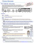
This guide provides quick start instructions for an experienced installer to set up and operate the
Extron DTP HDMI 230 digital video extender. The DTP HDMI 230 transmitter and receiver pair can
extend an HDCP-compliant HDMI signal up to 230 feet (70 m).
Installation
Step 1 — Mounting
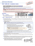
Turn off or disconnect all equipment power sources and mount the Tx and Rx units as required.
DTP HDMI 230 Tx Rear Panel
POWER
12V
0.7A MAX
7
DTP HDMI 230 Rx Rear Panel
SIG
INPUTS
LINK
DTP OUT
Tx Rx G Tx Rx
4
3
1
LINK
L
AUDIO
R
DTP IN
7
4
INPUTS
Step 2 — Connections
OUTPUTS
POWER
12V
0.7A MAX
IR
RS-232
2
SIG
OVER DTP
AUDIO
5
6
Front Panel
AUDIO
OVER DTP
a HDMI Input connector (Tx) — Connect an HDMI
cable between this port and the HDMI output port of
the digital video source.
IR
RS-232
Tx Rx G Tx Rx
NOTE: See the “LockIt™ Lacing Brackets“on the back of this guide for to
securely fasten the input HDMI connector to the transmitter.
DTP HDMI 230 Rx
3
b Audio input (Tx) — Connect an unbalanced stereo audio source to this 3.5 mm mini
stereo jack for an analog audio input.
Extron recommends that you terminate both cable ends in accordance with the
following specifications, at a minimum:
zz
TIA/EIA T 568 B
zz
24 AWG, solid conductor
CAT 6A, shielded
�
Transmit pin on connected unit
Receive pin on connected unit
Ground
Transmit pin on connected unit
Receive pin on connected unit
Tx Rx G Tx Rx
d DTP RJ-45 connectors — Connect transmitter DTP Out to receiver DTP In.
IR
serial control of a projector, connect the master device to the transmitter and the slave
device to the receiver via the RS-232 and IR captive screw connectors on both units.
Connected RS-232
and IR Device Pins
Tx/Rx
Pins
RS-232
c RS-232 and IR connectors — To pass serial or infrared data or control signals, such as
Pins:
12345678
1 White-orange
2 Orange
ATTENTION: Do not connect these devices to a computer data or telecommunications
network.
3
Link LED — Lights when a valid link is established between the units on the DTP cable.
e HDMI Output connector (Rx) — Connect a display with an HDMI input for display of the
transmitted direct digital image.
5
7
TP Wires
device to the receiver via the Audio captive screw connector. See the drawing below.
No Ground Here
L
L
R
R
No Ground Here
Unbalanced Stereo Output
White-brown
8 Brown
OUTPUTS
f Audio Output connector (Rx) — Connect a balanced or unbalanced stereo or mono audio
Do not tin the wires!
White-blue
6 Green
NOTE: See the “LockIt™ Lacing Brackets“on the back of this guide for to
securely fasten the output HDMI connector to the receiver.
Tip
Ring
Sleeves
Tip
Ring
White-green
4 Blue
Signal LED — Lights when the unit is receiving a TMDS clock signal on the HDMI input (transmitter) or
any valid signal on the DTP In connector (receiver).
Tip
Sleeves
Tip
TIA/EIA T
568 B
Pin Wire color
Balanced Stereo Output
ATTENTION: Connect the sleeves to the ground contact. DO NOT connect the sleeves to the negative (-) contacts.
L
AUDIO
R
DTP HDMI 230 • Setup Guide (Continued)
g Power connector — Connect an IEC power cord between the included 12 VDC
power supply and a 100-240 VAC, 50-60 Hz source. Connect the power supply to
either unit as shown at right. Use the included tie-wrap to strap the cord to the
captive screw connector.
Smooth
Ridges
Captive
Screw
Connector
NOTE: Only one power supply is required. A single power supply
connected to either unit in the pair powers both units. A power
supply is included with each transmitter.
3"
16 (5 mm) Max.
SECTION A–A
Power Supply
Output Cord
A
A
Operation
After all devices are powered up, the system is fully operational. See the definitions
of the power indications (shown at right), below:
Front Panel
Rear Panel
POWER
12V
0.6 A MAX
a Power LED (front panel) —
Amber — The unit is receiving power, either locally or remotely (on the DTP cable).
Green — The unit is powered on and is receiving an active HDMI signal, either on
the HDMI input if a transmitter, or transmitted on the DTP cable if a receiver.
1
2
b Power LED (rear panel) —
Amber — The unit is receiving power remotely (on the DTP cable).
Green — The unit is receiving power locally.
If any problems are encountered, verify that the cables are routed and connected properly. If your problems persist, call the
Extron S3 Sales and Technical Support Hotline that is closest to you, at the number shown below.
LockIt™ Lacing Brackets
Use an included LockIt Lacing Bracket to securely fasten an HDMI cable to each device as follows.
1. Plug the HDMI cable into the panel connection.
2. Loosen the HDMI connection mounting screw from the panel enough to allow the LockIt
lacing bracket to be placed over it. The screw does not have to be removed.
3
3. Place the LockIt lacing bracket on the screw and against the HDMI connector, then tighten the
screw to secure the bracket.
ATTENTION:
Do not overtighten the HDMI connector mounting screw. The shield
it fastens to is very thin and can easily be stripped.
4. Loosely place the included tie wrap around the HDMI connector and the LockIt lacing bracket
as shown.
5. While holding the connector securely against the lacing bracket, use pliers or similar tools to
tighten the tie wrap, then remove any excess length.
Extron Headquarters
+1.800.633.9876 (Inside USA/Canada Only)
Extron USA - West
Extron USA - East
+1.714.491.1500+1.919.850.1000
+1.714.491.1517 FAX
+1.919.850.1001 FAX
2
Extron Europe
+800.3987.6673
(Inside Europe Only)
+31.33.453.4040
+31.33.453.4050 FAX
Extron Asia
+800.7339.8766
(Inside Asia Only)
+65.6383.4400
+65.6383.4664 FAX
Extron Japan
+81.3.3511.7655
+81.3.3511.7656 FAX
© 2012 Extron Electronics All rights reserved.
Extron China
+4000.398766
Inside China Only
+86.21.3760.1568
+86.21.3760.1566 FAX
Extron Middle East
+971.4.2991800
+971.4.2991880 FAX
www.extron.com
2
1
3
4
Extron Korea
+82.2.3444.1571
+82.2.3444.1575 FAX
5
Extron India
1800.3070.3777
Inside India Only
+91.80.3055.3777
+91.80.3055.3737 FAX
68-2244-50
Rev A
07 12