1
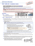
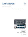
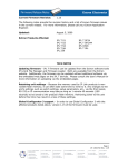
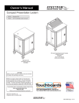
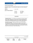
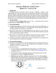
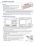
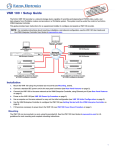
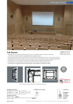
DTP T USW 233 • Setup Guide
This guide provides instructions for an experienced installer to set up and operate the
Extron DTP T USW 233 switching video transmitter. The DTP T USW 233 transmitter switches among
an analog video and two digital (HDMI) video inputs and, paired with a compatible receiver, can
extend the selected signal up to 230 feet (70 m). If the selected input is HDMI, the extended video
signal is HDCP-compliant.
POWER
12V
--A MAX
1
SIG
3
2
LINK
AUDIO
OVER DTP
RS-232
IR
INPUTS
RGB, Y, R-Y, B-Y
HDMI
HDMI
DTP OUT
Tx Rx G Tx Rx
3
1
2
2
5
4
10
REMOTE
CONTACT
1
2
3
G
TALLY
1
6
2
3 +V
7
RS-232
RESET
Tx Rx G
9
8
Installation
Step 1 — Mounting
Turn off or disconnect all equipment power sources and mount the transmitter as required.
Step 2 — Making Connections
Inputs
a Input 1 (RGB) connector — Connect a VGA cable between this port and the VGA output port of the analog video source.
b Input 2 and 3 (HDMI) connectors — Connect HDMI cables between these ports and the HDMI output ports of the digital video
sources.
NOTE: See the LockIt® Lacing Brackets on page 3 of this guide for to securely fasten the HDMI connectors to the transmitter.
c Audio input — Connect an unbalanced stereo audio source to this 3.5 mm mini stereo jack for an analog audio input.
NOTE: Audio is not embedded in the HDMI signal; it is transmitted simultaneously and is present on all inputs.
IR Device
Over DTP RS-232 and IR pass-through
Tx Rx G Tx Rx
IR
DTP RJ-45 output, connect the controlling device to the transmitter via the RS-232 and IR
captive screw connector. Connect the device to be controlled to the receiver.
RS-232
d RS-232 and IR connector — To pass serial or infrared data or control signals on the Over
OVER DTP
Rx Tx Gnd
DTP output to receiver
Tx Rx Gnd
e DTP RJ-45 connector — Connect the transmitter DTP Out port to the DTP In port on the
receiver. Extron recommends that you terminate both cable ends in accordance with the
following specifications, at a minimum:
•
TIA/EIA T 568B
•
24 AWG, solid conductor
RS-232 Device
Pins:
12345678
• CAT 6a, shielded
TIA/EIA T
568B
Pin Wire color
1 White-orange
2
ATTENTION: Do not connect this device to a computer data or telecommunications network.
Orange
3
White-green
4
Blue
5
White-blue
Green
Signal LED — Lights when the unit is outputting a TMDS clock signal on the DTP output.
6
Link LED — Lights when a valid link is established between the units on the DTP cable.
7
White-brown
8
Brown
Remote control
TP Wires
f Remote Contact port — If desired, for contact closure control, plug a locally-contructed contact closure control device into this
3.5 mm, 4-pole captive screw port. Momentarily short the pin for the desired input (1, 2, or 3) to G to select that input. To force an
input to be always selected, leave the short in place.
NOTES:
• Contact closure control overrides front panel input selections.
• For contact closure control, auto-input switching mode must be off (see Selecting the switch mode on the next page).
1
DTP T USW 233 • Setup Guide (Continued)
g Remote Tally port — If desired, to remotely identify the currently selected input, plug a locally-constructed device into this 3.5 mm,
4-pole captive screw connector. Connect the power wire for the device into the +V pin and connect the ground wire for the each
indicator into the corresponding tally output pin: 1, 2, or 3.
When an input is selected, by either contact closure or front panel selection, the corresponding tally output pin shorts to ground,
closing the circuit and lighting the connected indicator (LED).
REMOTE
panel 3.5 mm, 3-pole captive screw connector for remote control of the switching transmitter.
RS-232
V Tx Rx G
h Remote RS-232 port — Plug a serial RS-232 device into the switching transmitter via this rear
Reset button
Tx Rx Gnd
i Reset button — This button initiates two levels of reset. For different reset levels, use an
RS-232 Device
Extron Tweeker or small screwdriver to press and hold the recessed button while the switcher
is running or while applying power. See the DTP T USW 233 User Guide, available at www.extron.com, for details.
Power
Smooth
j Power connector — Connect an IEC power cord between the included 12 VDC
Ridges
power supply and a 100-240 VAC, 50-60 Hz source. Connect the power supply to
either unit, transmitter or receiver, as shown at right. Use the included tie-wrap to
strap the cord to the captive screw connector.
Captive
Screw
Connector
NOTE: Only one power supply is required. A single power supply connected to
either unit in the pair powers both units. A power supply is included with the
transmitter.
3"
16 (5 mm) Max.
SECTION A–A
Power Supply
Output Cord
A
A
Front panel Configuration port
a Configuration port — Plug a PC or other controlling device into the switching transmitter via this front
panel mini-USB connector for remote configuration of the switching transmitter.
AUTO
SWITCH
Operation
CONFIG
Switching inputs
1
Select the desired input by pressing the associated input button. Observe that the
LED for the selected input lights.
Press the button.
The LED lights green.
NOTE: The switcher must be in normal (manual) mode (see below).
1
2
3
Selecting the switch mode
MODE
In auto-input switching mode, the switcher selects to the highest numbered input
with a sync signal present. Turn auto-input switching mode on and off as follows:
AUTO
NORMAL
1. Press and hold the Mode (Input 1) button.
2. Press and release the button for the desired mode:
Auto (Input 3) — The Auto Switch LED lights.
Press the and HOLD the Mode button.
Press and release the Auto or Normal button.
Auto Switch lights (auto)
or goes out (normal).
Normal (Input 2) — The Auto Switch LED goes off.
1
3. Release the Mode button.
Locking and unlocking the front panel
(Executive mode)
MODE
2
AUTO
NORMAL
The switcher has a front panel lock feature that locks the front panel. If you try to make
front panel input selections when the panel is locked, all front panel LEDs flash three
times. Toggle the front panel lock on and off by pushing and holding all three Input
buttons simultaneously for 5 seconds. All front panel LEDs flash three times.
Release the buttons.
Interpreting the Status LEDs
HDCP LEDs (2 and 3) —Indicate that the corresponding input signal is HDCP encrypted.
Release the Mode button.
Press the and HOLD the all three Input buttons.
1
2
MODE
NORMAL
3
AUTO
All three LEDs flash three times. Release the Input buttons.
Signal LEDs (1 through 3) —Indicate that the switcher detects horizontal sync
(Signal LED 1) or TMDS clock (Signal LED 2 and Signal LED 3) signals on the associated input.
2
AUTO
SWITCH
3
STATUS
1
SIGNAL
HDCP
2
3
LockIt® Lacing Brackets
Use the included LockIt Lacing Brackets to securely fasten both HDMI cables as follows.
1. Plug the HDMI cable into the panel connection.
2. Loosen the HDMI connection mounting screw from the panel enough to allow the LockIt lacing
bracket to be placed over it. The screw does not have to be removed.
3
3. Place the LockIt lacing bracket on the screw and against the HDMI connector, then tighten the
screw to secure the bracket.
2
1
ATTENTION: Do not overtighten the HDMI connector mounting screw. The shield it fastens
to is very thin and can easily be stripped.
4. Loosely place the included tie wrap around the HDMI connector and the LockIt lacing bracket as
3
shown.
5. While holding the connector securely against the lacing bracket, use pliers or similar tools to
4
5
tighten the tie wrap, then remove any excess length.
Application Diagram
Extron
DTP T USW 233
VCR
DVD
DOC
CAM
LAP
TOP
PC
DTP Transmitter
ON
Extron
TouchLink
Control
System
OFF
LAY
DISP E
MUT
EEN
SCR
UP
EEN
SCR N
DOW
Extron
DTP HDMI 230 D Rx
TCP/IP
RE
OV
K
LIN
RS-
ER
23
2
Tx
T
3
HD
2
HD
1
WER
PO
V
12 MAX
--A
DIO
AU
IN
PU
RG
B,
Y,
R-Y
,B
DTP
MI
OU
Rx
DT
P
G
Tx
TE
2
3
G
1
2
3
2
23
RS-
Y
LL
TA
CT
NTA
CO
IR
1
SIG
MO
+V
Tx
Rx
G
RES
ET
Switcher
Control
100
AY
REL
LINK
3
ACT
UT
INP
IR
1
3
1
COM
RX
IPL
TX
250
R
4
3
2
1
4
2
1
2
Rx
4
2
Receiver
Extron
IPL 250
OU
-Y
ER
OV
P
DT
IR
-232
RS
Tx
CATx Cable
Up to 230' (70 m)
MI
S
UT
TP
3
AV Device
Control
Rx
G
Tx
Rx
IO
D
AU
AV Device
Control
HDMI with
Embedded
Audio
TS
Document
Camera
Laptop
®
VGA
Laptop
HDMI
HDMI
Flat Panel Display
with Speakers
Figure 1. Typical Switching Transmitter Application
3
Extron Headquarters
+800.633.9876 Inside USA/Canada Only
Extron USA - West
Extron USA - East
+1.714.491.1500+1.919.850.1000
+1.714.491.1517 FAX
+1.919.850.1001 FAX
4
Extron Europe
+800.3987.6673
Inside Europe Only
+31.33.453.4040
+31.33.453.4050 FAX
Extron Asia
+65.6383.4400
+65.6383.4664 FAX
Extron Japan
+81.3.3511.7655
+81.3.3511.7656 FAX
Extron China
+86.21.3760.1568
+86.21.3760.1566 FAX
Extron Middle East
+971.4.299.1800
+971.4.299.1880 FAX
Extron Korea
+82.2.3444.1571
+82.2.3444.1575 FAX
Extron India
1800.3070.3777
(Inside India Only)
+91.80.3055.3777
+91.80.3055.3737 FAX
© 2013 Extron Electronics All rights reserved. All trademarks mentioned are the property of their respective owners. www.extron.com
68-2490-50 Rev. A
11 13