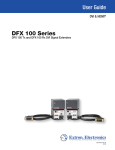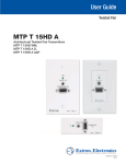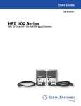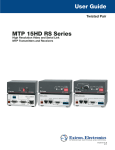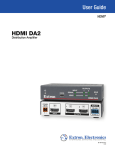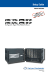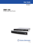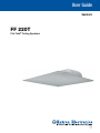
1
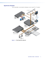
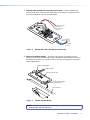
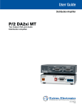
User Guide
Speakers
FF 220T
Flat Field® Ceiling Speakers
68-1683-01
Rev. B
08 13
Safety Instructions
Safety Instructions • English
WARNING: This symbol,
, when used on the product, is intended
to alert the user of the presence of uninsulated dangerous voltage
within the product’s enclosure that may present a risk of electric
shock.
Chinese Simplified(简体中文)
警告:
产品上的这个标志意在警告用户该产品机壳内有暴露的危险
电压,有触电危险。
注 意:
ATTENTION: This symbol,
, when used on the product, is intended
to alert the user of important operating and maintenance (servicing)
instructions in the literature provided with the equipment.
产 品 上 的 这个 标 志 意 在 提 示用 户设 备 随 附 的 用 户手 册 中 有
重要的操作和维护(维修)说明。
关于我们产品的安全指南、遵循的规范、EMI/EMF 的兼容性、无障碍
使用的特性等相关内容,敬请访问 Extron 网站 www.extron.cn,参见 Extron
For information on safety guidelines, regulatory compliances, EMI/EMF
compatibility, accessibility, and related topics, see the Extron Safety and
Regulatory Compliance Guide, part number 68-290-01, on the Extron
website, www.extron.com.
安全规范指南,产品编号 68-290-01。
Instructions de sécurité • Français
Chinese Traditional(繁體中文)
avertissement: Ce pictogramme,
, lorsqu’il est utilisé sur le
produit, signale à l’utilisateur la présence à l’intérieur du boîtier
du produit d’une tension électrique dangereuse susceptible de
provoquer un choc électrique.
attention: Ce pictogramme,
, lorsqu’il est utilisé sur le produit,
signale à l’utilisateur des instructions d’utilisation ou de maintenance
importantes qui se trouvent dans la documentation fournie avec le
matériel.
Pour en savoir plus sur les règles de sécurité, la conformité à la
réglementation, la compatibilité EMI/EMF, l’accessibilité, et autres sujets
connexes, lisez les informations de sécurité et de conformité Extron,
réf. 68-290-01, sur le site Extron, www.extron.fr.
Sicherheitsanweisungen • Deutsch
warnung:
Dieses Symbol
auf dem Produkt soll den
Benutzer darauf aufmerksam machen, dass im Inneren des
Gehäuses dieses Produktes gefährliche Spannungen herrschen,
die nicht isoliert sind und die einen elektrischen Schlag
verursachen können.
Vorsicht: Dieses Symbol
auf dem Produkt soll dem Benutzer in
der im Lieferumfang enthaltenen Dokumentation besonders wichtige
Hinweise zur Bedienung und Wartung (Instandhaltung) geben.
Weitere Informationen über die Sicherheitsrichtlinien, Produkthandhabung,
EMI/EMF-Kompatibilität, Zugänglichkeit und verwandte Themen finden Sie
in den Extron-Richtlinien für Sicherheit und Handhabung (Artikelnummer
68-290-01) auf der Extron-Website, www.extron.de.
Instrucciones de seguridad • Español
ADVERTENCIA: Este símbolo,
, cuando se utiliza en el producto,
avisa al usuario de la presencia de voltaje peligroso sin aislar dentro
del producto, lo que puede representar un riesgo de descarga
eléctrica.
ATENCIÓN: Este símbolo,
, cuando se utiliza en el producto, avisa
al usuario de la presencia de importantes instrucciones de uso y
mantenimiento recogidas en la documentación proporcionada con
el equipo.
Para obtener información sobre directrices de seguridad, cumplimiento
de normativas, compatibilidad electromagnética, accesibilidad y
temas relacionados, consulte la Guía de cumplimiento de normativas
y seguridad de Extron, referencia 68-290-01, en el sitio Web de Extron,
www.extron.es.
警告:
若產品上使用此符號,是為了提醒使用者,產品機殼內存在著
可能會導致觸電之風險的未絕緣危險電壓。
注意
若產品上使用此符號,是為了提醒使用者。
有關安全性指導方針、法規遵守、EMI/EMF 相容性、存取範圍和相關主題的詳細
資訊,請瀏覽 Extron 網站:www.extron.cn,然後參閱《Extron 安全性與法規
遵守手冊》,準則編號 68-290-01。
Japanese
警告: この記号
が製品上に表示されている場合は、筐体内に絶縁されて
いない高電圧が流れ、感電の危険があることを示しています。
注意: この記号
が製品上に表示されている場合は、本機の取扱説明書に
記載されている重要な操作と保守(整備)の指示についてユーザーの
注意を喚起するものです。
安全上のご注意、法規厳守、EMI/EMF適合性、その他の関連項目に
ついては、エクストロンのウェブサイトwww.extron.jpより
『 Extron Safety and Regulatory Compliance Guide 』(P/N 68-290-01) をご覧ください。
Korean
경고: 이 기호
, 가 제품에 사용될 경우, 제품의 인클로저 내에 있는 접지되지
않은 위험한 전류로 인해 사용자가 감전될 위험이 있음을 경고합니다.
주의:
이 기호
, 가 제품에 사용될 경우, 장비와 함께 제공된 책자에 나와
있는 주요 운영 및 유지보수(정비) 지침을 경고합니다.
안전 가이드라인, 규제 준수, EMI/EMF 호환성, 접근성, 그리고 관련
항목에 대한 자세한 내용은 Extron 웹 사이트(www.extron.co.kr)의
Extron 안전 및 규제 준수 안내서, 68-290-01 조항을 참조하십시오.
Conventions Used in this Guide
In this user guide, the following are used:
ATTENTION: An attention is used to indicate potential damage to product or property.
CAUTION: A caution indicates a potential hazard to equipment or data.
NOTE: A note draws attention to important information.
Specifications Availability
Product specifications are available on the Extron website, www.extron.com.
Copyright
© 2013 Extron Electronics. All rights reserved.
Trademarks
All trademarks mentioned in this guide are the properties of their respective owners.
The following registered trademarks(®), registered service marks(SM), and trademarks(TM) are the property of
RGB Systems, Inc. or Extron Electronics:
Registered Trademarks (®)
AVTrac, Cable Cubby, CrossPoint, eBUS, EDID Manager, EDID Minder, Extron, Flat Field, GlobalViewer, Hideaway, Inline, IP Intercom, IP Link,
Key Minder, LockIt, MediaLink, PlenumVault, PoleVault, PowerCage, PURE3, Quantum, SoundField, SpeedMount, SpeedSwitch, System
Integrator, TeamWork, TouchLink, V‑Lock, VersaTools, VN‑Matrix, VoiceLift, WallVault, WindoWall, XTP and XTP Systems
Registered Service Mark(SM) : S3 Service Support Solutions
Trademarks (™)
AAP, AFL (Accu‑Rate Frame Lock), ADSP (Advanced Digital Sync Processing), AIS (Advanced Instruction Set), Auto‑Image, CDRS (Class D
Ripple Suppression), DDSP (Digital Display Sync Processing), DMI (Dynamic Motion Interpolation), Driver Configurator, DSP Configurator, DSVP
(Digital Sync Validation Processing), FastBite, FOXBOX, IP Intercom HelpDesk, MAAP, MicroDigital, ProDSP, QS‑FPC (QuickSwitch Front Panel
Controller), Scope‑Trigger, SIS, Simple Instruction Set, Skew‑Free, SpeedNav, Triple‑Action Switching, XTRA, ZipCaddy, ZipClip
Contents
Introduction............................................................ 1
Features.............................................................. 1
Application Example............................................ 2
Installation............................................................... 3
Installation Considerations................................... 3
Installing the Speaker.......................................... 4
Wiring for Installation in a 70 V or 100 V Audio
Distribution System (through the transformer)
....................................................................... 6
Wiring for Installation with Direct 8 ohm
Connection to an Amplifier (bypassing the
transformer).................................................... 8
Finishing Steps, All Installation Types............... 9
Reference Information........................................ 11
Dimensions....................................................... 11
FF 220T User Guide • Contents
iv
Introduction
This user guide contains information about the Extron FF 220T Flat Field speaker. This
speaker is designed for use in plenum rated ceiling spaces and can be dropped into a
square (2-foot by 2-foot or 600 mm by 600 mm) or rectangular (2-foot by 4-foot or 600 mm
by 1200 mm with supplied cross bars) false ceiling tile space on a T-bar grid.
The FF 220T features a low profile design that houses a 3-inch driver and has the
appearance of a standard ventilation grill. All the drivers and components above the ceiling
are hidden behind the grill.
Features
•
Drop-in ceiling tile speakers for suspended ceilings
•
UL 2043 plenum rated enclosure
•
Extron patent pending Flat Field technology for consistent sound levels across the
listening area, reducing the number of speakers required
•
A 3-inch (7.6 cm) horn-loaded, full range driver provides extended low frequency
response.
•
The white perforated grille matches the appearance of air conditioning vents.
•
8 ohm direct or 70/100 volt operation with 16, 8, 4, 2, and 1 watt selectable power taps
accessed with speaker wiring connections inside the rear panel
•
Frequency response of 68 Hz to 18 kHz
•
16 watts continuous pink noise, 32 watts continuous program rated
•
Wide 170° dispersion
•
Low profile enclosure for plenum environments
•
5 year parts and labor warranty
FF 220T User Guide • Introduction
1
Application Example
The illustration below is one example of configuring a system using the FF 220T speakers.
Desk Microphones
VCR
DVD
DOC
CAM
TOP
LAP
PC
ON
OFF
LAY
DISP E
MUT
EEN
SCR
UP
UT
Extron
TLP 700TV
7" TouchLink™
Tabletop
Touchpanel
2
TP
-23
RS
OU
A
B
L
R
L
6
O
DI 3
5
T
PU 4
8
IN
R
7
AU
2
1
UT
L
B
RG, R-Y
B-Y
R
TP
OU
D
LISTE
1T23
U S I.T.E.
Y,
C
6
8
RG
I
B
DV
7
B
RG
EEN
SCR N
DOW
Ethernet
3 YC
R-Y
1 VID
B-Y
I
0Hz
50-6
N
5
TCP/IP
Network
Y
VID
Extron
IN1508
Scaling Presentation
Switcher
240V
P
100-
U
T
4
2
Extron
IPL 250
IP Link Ethernet
Control
Processor
Laptop
PC
AY2
REL
1
IR 2
1
2
COM
RX
TX
1
G
AY4
REL
3
3
3
COM
RX
TX
LAN
S
IR 4
RX
UT
INP 4
3
2
G
S
TS
1
SC
COMRT
TX
S
G
S
G
ER
POW
12VmA
500X
MA
P 64
DM
)
2(1
-23
RS
I/O
Tx
)
2(2
2
1
1
4
TS
PU
E IN
LIN
C/
3
MI
MIC
8V
+4
3
2
Extron
DMP 64
2
1
1
6
2
5
3
-23
RS
T
SE
RE
RS-232
6
Tx
O
U
T
P
U
T
S
N
LA
Rx
Rx
4
3
6
5
4
5
R
4
WE
PO
12V MA
A
1.5
X
Digital Matrix
Processor
3C
-70
V
A 200
XP
G
RIN
2 WI S
UT
S
AS
CL OUTP
70V
3
4/8 2
F
HP
1
3
CH
Hz
80
S
UT
OFF
INP
3
2
1
L
VE
LE
3
2
0
1
STANDBY
TIMER DISABLE
OTE
REM
R/
ITE T
LIM TEC
PRO
0
0
L
NA
SIG
0 Hz
50/6
240V MAX
100- 1.3A
E
TIV BY
- AC ND
EEN - STA
GR BER
AM
d
Liste
IDEO
17TTIO/V S
AUD RATU
APPA
Extron
XPA 2003C 70V
Combo Power Amplifier
Extron
FF 220T
Plenum 2' x 2' Flat Field
Ceiling Speakers
Extron
SI 28
Surface-Mount
Speakers
Figure 1. FF 220T Application Diagram
FF 220T User Guide • Introduction
2
Installation
The Installation section describes:
•
Installation Considerations
•
Installing the Speaker
Installation Considerations
ATTENTION: Installation and service must be performed by authorized personnel only.
NOTE: The FF 220T comes in two ceiling tile configurations depending on the tile unit
of measurement:
• US version (part #42-141-03) — Drops into 2-foot x 2-foot (61 cm x 61 cm) or
2-foot x 4-foot (61 cm x 122 cm) suspended tile ceilings
• Metric version (part #42-141-23) — Drops into 60 cm x 60 cm
(1.97-foot x 1.97-foot) or 60 cm x 120 cm (1.97-foot x 3.94-foot) suspended
tile ceilings
Be sure to order the correct part number as the two configurations are not
interchangeable and will not fit correctly.
Installation of conduit and conduit adapters must conform to all applicable building codes
and local ordinances.
•
Installation in a plenum-rated environment requires a wire gauge of 12 AWG to
18 AWG. Conduit may be required.
NOTE: If you are daisy chaining speakers in 70 V or 100 V configuration, the
maximum wire gauge is 16 AWG. If you are daisy chaining speakers in direct (8
ohm) configuration, the maximum wire gauge is 14 AWG.
•
If using secondary attachment points, the installer must provide the cables.
•
Wiring connections depend on whether or not a distributed (70 or 100 volt) audio
system is installed with these speakers.
FF 220T User Guide • Installation
3
Installing the Speaker
1. Power down — Power down all attached devices before proceeding.
2. Remove the suspended ceiling tile — Remove the square ceiling tile where the
FF 220T will be installed as shown below. If the ceiling has rectangular tiles, cut the tile
in half.
Cut Material
Draw Line At
Halfway Point
Rectangular Ceiling Tile
Ceiling Tile
T-rail
Crosspiece
(supplied)
3. Remove the terminal cover plate — Loosen (do not remove) the two screws on the
top terminal cover plate and remove the cover plate as shown below.
Loosen but do not remove
the 2 transformer cover plate
screws in the 2 keyhole slots.
Transformer Cover Plate
Figure 2.
Removing the Terminal Cover Plate
FF 220T User Guide • Installation
4
4. Routing cables through the transformer cover plate — Slide and remove the
terminal cover plate. The transformer cover plate is mounted to the speaker with the
transformer side down. See the illustration below.
(Black) To Speaker
(-) Terminal
C
O
M
C
N
O
C
M
16
16
W
W
8
8
W
W
4
4
W
W
2
2
W
W
1
1
W
W
N
C
(Red) To Speaker
(+) Terminal
0V
70
V
10
To Second
Speaker
Black (-)
Red (+)
Black (-)
Red (+)
From Amplifier
(70V/100V)
Figure 3.
Routing the Cables Through the Cover Plate
5. When using flexible conduit — Route the wires through the conduit. Insert the
conduit into the cover plate opening using an appropriate conduit adapter, and secure
the conduit to the plate. Pull the wires out of the conduit and through the cover plate.
See the figure below.
Flexible Conduit Adapter
Flexible Conduit
Transformer Cover Plate
Secondary Support Cable
Pass Through Loop
Rear of Speaker
Figure 4.
Flexible Conduit Wiring
NOTE: Installation of conduit and conduit adapters should conform to all applicable
building codes and local ordinances.
FF 220T User Guide • Installation
5
When using speaker wires without a conduit — Secure the cable clamp adapter
(included) to the cover plate and insert the wires through the clamp. Tighten the clamp
screws. See the following illustration.
Cable Clamp
Adapter
Transformer Cover Plate
Secondary Support Cable
Pass Through Loop
Rear of Speaker
Figure 5.
Wiring Without Conduit
6. Proceed to step 7 (going through the transformer) or 9 (bypassing the transformer) for
the appropriate wiring procedure for either a distributed audio system (70 V or 100 V
line distribution through the transformer) or for a direct connection from an amplifier
(bypassing the transformer).
NOTE: In the 70 V or 100 V distribution system block diagram below, an optional
speaker has been added as an example of daisy chaining FF 220T speakers to a
single amplifier output.
Wiring for Installation in a 70 V or 100 V Audio Distribution System (through
the transformer)
7. Connect cables from the amplifier to the transformer on the FF 220T terminal cover
plate.
Additional
FF 220T
Speaker(s)
Transformer
Plate
Transformer
Plate
Amplifier
70 V or 100 V Distribution System
(through the transformer)
An additional FF 220T
can be attached to
to the tap connector.
See step 7f.
FF 220T
FF 220T
Figure 6.
70 V or 100 V Distribution System
a. If a conduit is used, pull the wires from the amplifier through and out of the conduit.
FF 220T User Guide • Installation
6
b. Route the two wires from the amplifier through the cover plate hole to the
transformer side.
c. Strip 3/16 inch (5 mm) from the wire ends and keep the wire end strands together
by twisting them. Do not tin the wires.
d. Secure the wires to the appropriate taps on the captive screw connectors of the
seven-connector terminal block (on the transformer side of the cover plate) as
indicated on the tap label. See the note below.
100 V 70 V
NOTE: Observe the 70 V or 100 V system designation as indicated on the
tap label.
COM 16 W
8W
4W
2W
1W
NC
COM
16 W
8W
4W
2W
1W
NC
When wiring to a single speaker, the black negative (-) wire attaches to the “COM”
terminal, and the red positive (+) wire attaches to the desired terminal tap. See
below.
From Amplifier (+)
70
C
O
M
N
C
C
O
M
16
16
W
W
8
8
W
W
4
4
W
W
2
2
W
W
1
1
W
W
N
C
Red Wire
0V
V
10
Black Wire
From Amplifier (-)
Figure 7.
Wiring to a Single Speaker
e. Use a small flat blade screwdriver to tighten the terminal block screws.
W
W
2
2
W
W
4
4
W
W
8
8
C
O
M
N
C
C
O
M
16
16
W
W
Red Wires
1
1
W
W
N
C
f. To wire additional speakers, route the speaker wires from the second speaker
through the cover plate hole to the transformer side. Twist the black negative (-)
wires together and the red positive (+) wires together before inserting them into the
terminal block. Additional speakers can be daisy-chained this way. See below.
Black Wires
From Amplifier (+)
0V
70
V
10
To Next Speaker (terminal tap)
From Amplifier (-)
To Next Speaker (COM terminal)
Figure 8.
Wiring to Additional Speakers
FF 220T User Guide • Installation
7
8. Connect wires from the transformer to the speaker.
a. Keep the wire strands together by twisting them (do not tin the wires).
b. Connect the red positive (+) wire to the + speaker terminal and connect the black
negative (-) wire to the - speaker terminal as shown below.
Transformer Cover Plate
Red Wire
To transformer
Black Wire
Figure 9.
Rear of Speaker
Wiring the Speaker to the Transformer
c. Proceed to step 10.
Wiring for Installation with Direct 8 ohm Connection to an Amplifier
(bypassing the transformer)
9. See the block diagram below.
Transformer
Plate
FF 220T
Amplifier
Direct 8 ohm Connection
(bypassing the transformer)
Figure 10. Direct 8 Ohm Connection
a. Route the wires from the amplifier to the speaker using the same procedure for
routing speaker wire (and conduit if applicable) through the cover plate as described
in step 5. Strip 3/16 inch (5 mm) from the ends of the two speaker
wire leads (+ and -) coming from the amplifier. Keep the wire strands together by
twisting them (do not tin the wires), and secure the wires to the input terminals of
the speaker, observing the correct polarity.
FF 220T User Guide • Installation
8
b. Connect the red positive (+) wire to the + speaker terminal and the black negative (-)
wire to the - speaker terminal depending on whether one or two speakers are being
connected.
Red Wire
From Amplifier
To Second Speaker
From Amplifier
To Second Speaker
Black Wire
Red Wire
From Amplifier
Black Wire
Two Speakers
One Speaker
Figure 11. Wiring the Speaker Terminals
Finishing Steps, All Installation Types
10.Replace the transformer cover plate and tighten the two cover plate screws that were
loosened in step 3.
11.Temporarily test the system and speakers by powering on the amplifier and listening for
the correct response from the speakers, then disconnect power from the amplifier.
12.For installation in a square ceiling grid, remove a tile and place the speaker on the
existing support rails and position it so that the speaker edges are hidden by the
support rails, as shown below.
Extron
FF 220T
Ceiling
Speakers
Ceiling Tile
Ceiling Tile
Rails
Figure 12. Installation in a Square Ceiling Grid
FF 220T User Guide • Installation
9
For installations in a rectangular ceiling grid, replace half of the rectangular tile which
was cut in half in step 2. Install the supplied T-rail crosspiece, then place the speaker on
the grid and position it so that the speaker edges are hidden by the support rails and
T-rails, as shown below.
Extron
FF 220T
Ceiling
Speakers
Ceiling Tile
Existing
Ceiling Tile
Rails
T-rail
Crosspiece
(supplied)
Figure 13. Installation in a Rectangular Ceiling Grid
FF 220T User Guide • Installation
10
13.If secondary support cables are being used, install them. See the illustration below.
NOTE: Observe all applicable building codes and local ordinances when installing
the speaker.
Anchor this end to a
suitable secure point.
Route the secondary support
cable through the line retainer
and bend-up tab.
Secondary
Support
Cable
Bend-up Tab
Figure 14. Installing a Secondary Support Cable
a. Temporarily remove a ceiling tile adjacent to the speaker and set it aside.
b. Connect a secondary support cable through the cable pass through loop, and
attach it to one of the bend-up tabs located on either side of the speaker.
c. Attach the other end of the cable to a sturdy part of the building (studs, roof struts,
or the like).
d. For additional support lines repeat as needed.
e. Replace all ceiling tiles.
14.Check all wiring before powering up the amplifier.
FF 220T User Guide • Installation
11
Reference
Information
Dimensions
A
A
D
C
B
U.S. Version
Metric Version
A
23.75" (60.35 cm)
57.4 cm (23.4")
B
3.25" (8.3 cm)
8.3 cm (3.25”)
C
8.0" (20.32 cm)
20.32 cm (8.0”)
D
3.5" (8.89 cm)
8.89 cm (3.5”)
FF 220T User Guide • Reference Information
12
Extron Warranty
Extron Electronics warrants this product against defects in materials and workmanship for a period of five years
from the date of purchase. In the event of malfunction during the warranty period attributable directly to faulty
workmanship and/or materials, Extron Electronics will, at its option, repair or replace said products or components,
to whatever extent it shall deem necessary to restore said product to proper operating condition, provided that it is
returned within the warranty period, with proof of purchase and description of malfunction to:
USA, Canada, South America,
and Central America:
Extron Electronics
1230 South Lewis Street
Anaheim, CA 92805
U.S.A.
Japan:
Extron Electronics, Japan
Kyodo Building, 16 Ichibancho
Chiyoda-ku, Tokyo 102-0082
Japan
Europe, Africa, and the Middle
East:
Extron Europe
Hanzeboulevard 10
3825 PH Amersfoort
The Netherlands
China:
Extron China
686 Ronghua Road
Songjiang District
Shanghai 201611
China
Asia:
Extron Asia
135 Joo Seng Road, #04-01
PM Industrial Bldg.
Singapore 368363
Singapore
Middle East:
Extron Middle East
Dubai Airport Free Zone
F12, PO Box 293666
United Arab Emirates, Dubai
This Limited Warranty does not apply if the fault has been caused by misuse, improper handling care, electrical
or mechanical abuse, abnormal operating conditions, or modifications were made to the product that were not
authorized by Extron.
NOTE: If a product is defective, please call Extron and ask for an Application Engineer to receive an RA (Return
Authorization) number. This will begin the repair process.
USA: (714) 491-1500
Asia:65.6383.4400
Europe:31.33.453.4040
Japan:81.3.3511.7655
Units must be returned insured, with shipping charges prepaid. If not insured, you assume the risk of loss or damage
during shipment. Returned units must include the serial number and a description of the problem, as well as the
name of the person to contact in case there are any questions.
Extron Electronics makes no further warranties either expressed or implied with respect to the product and its quality,
performance, merchantability, or fitness for any particular use. In no event will Extron Electronics be liable for direct,
indirect, or consequential damages resulting from any defect in this product even if Extron Electronics has been
advised of such damage.
Please note that laws vary from state to state and country to country, and that some provisions of this warranty may
not apply to you.
Extron Headquarters
+1.800.633.9876 (Inside USA/Canada Only)
Extron USA - West
Extron USA - East
+1.714.491.1500+1.919.850.1000
+1.714.491.1517 FAX
+1.919.850.1001 FAX
Extron Europe
+800.3987.6673
(Inside Europe Only)
+31.33.453.4040
+31.33.453.4050 FAX
Extron Asia
+65.6383.4400
+65.6383.4664 FAX
Extron Japan
+81.3.3511.7655
+81.3.3511.7656 FAX
Extron China
+86.21.3760.1568
+86.21.3760.1566 FAX
Extron Middle East
+971.4.299.1800
+971.4.299.1880 FAX
© 2013 Extron Electronics All rights reserved. www.extron.com
Extron Korea
+82.2.3444.1571
+82.2.3444.1575 FAX
Extron India
1800.3070.3777
(Inside India Only)
+91.80.3055.3777
+91.80.3055.3737 FAX