1
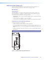
User Guide
USB Extenders
USER MANUAL
USB Extender Plus
T/R Series
Twisted Pair Extenders for USB Peripherals
68-2652-01 Rev. B
09 15
Safety Instructions
Safety Instructions • English
WARNING: This symbol,
, when used on the product, is intended to
alert the user of the presence of uninsulated dangerous voltage within the
product’s enclosure that may present a risk of electric shock.
ATTENTION: This symbol,
, when used on the product, is intended
to alert the user of important operating and maintenance (servicing)
instructions in the literature provided with the equipment.
For information on safety guidelines, regulatory compliances, EMI/EMF
compatibility, accessibility, and related topics, see the Extron Safety and
Regulatory Compliance Guide, part number 68-290-01, on the Extron website,
www.extron.com.
Instructions de sécurité • Français
AVERTISSEMENT : Ce pictogramme,
, lorsqu’il est utilisé sur le
produit, signale à l’utilisateur la présence à l’intérieur du boîtier du produit
d’une tension électrique dangereuse susceptible de provoquer un choc
électrique.
ATTENTION : Ce pictogramme,
, lorsqu’il est utilisé sur le produit,
signale à l’utilisateur des instructions d’utilisation ou de maintenance
importantes qui se trouvent dans la documentation fournie avec le
matériel.
Pour en savoir plus sur les règles de sécurité, la conformité à la réglementation,
la compatibilité EMI/EMF, l’accessibilité, et autres sujets connexes, lisez les
informations de sécurité et de conformité Extron, réf. 68-290-01, sur le site
Extron, www.extron.com.
Sicherheitsanweisungen • Deutsch
WARNUNG: Dieses Symbol
auf dem Produkt soll den Benutzer
darauf aufmerksam machen, dass im Inneren des Gehäuses dieses
Produktes gefährliche Spannungen herrschen, die nicht isoliert sind
und die einen elektrischen Schlag verursachen können.
VORSICHT: Dieses Symbol
auf dem Produkt soll dem Benutzer in der
im Lieferumfang enthaltenen Dokumentation besonders wichtige Hinweise
zur Bedienung und Wartung (Instandhaltung) geben.
Weitere Informationen über die Sicherheitsrichtlinien, Produkthandhabung,
EMI/EMF-Kompatibilität, Zugänglichkeit und verwandte Themen finden Sie in
den Extron-Richtlinien für Sicherheit und Handhabung (Artikelnummer
68-290-01) auf der Extron-Website, , www.extron.com.
Инструкция по технике безопасности • Русский
ПРЕДУПРЕЖДЕНИЕ:
Данный символ,
, если указан
на продукте, предупреждает пользователя о наличии
неизолированного опасного напряжения внутри корпуса
продукта, которое может привести к поражению
электрическим током.
ВНИМАНИЕ: Данный символ,
, если указан на продукте,
предупреждает пользователя о наличии важных инструкций
по эксплуатации и обслуживанию в руководстве,
прилагаемом к данному оборудованию.
Для получения информации о правилах техники безопасности,
соблюдении нормативных требований, электромагнитной
совместимости (ЭМП/ЭДС), возможности доступа и других
вопросах см. руководство по безопасности и соблюдению
нормативных требований Extron на сайте Extron: , www.extron.com,
номер по каталогу - 68-290-01.
安全说明 • 简体中文
警告:
产品上的这个标志意在警告用户该产品机壳内有暴露的危险 电压,
有触电危险。
注 意:
产 品 上 的 这个 标 志 意 在 提 示用 户 设 备 随 附 的 用 户 手 册 中 有
重要的操作和维护(维修)说明。
关于我们产品的安全指南、遵循的规范、EMI/EMF 的兼容性、无障碍
使用的特性等相关内容,敬请访问 Extron 网站 , www.extron.com,参见
Extron 安全规范指南,产品编号 68-290-01。
安全記事 • 繁體中文
警告:
若產品上使用此符號,是為了提醒使用者,產品機殼內存在著
可能會導致觸電之風險的未絕緣危險電壓。
注意
若產品上使用此符號,是為了提醒使用者,設備隨附的用戶手冊中有重
要的操作和維護(維修)説明。
有關安全性指導方針、法規遵守、EMI/EMF 相容性、存取範圍和相關主題的詳細資
訊,請瀏覽 Extron 網站:www.extron.com,然後參閱《Extron 安全性與法規
遵守手冊》,準則編號 68-290-01。
安全上のご注意 • 日本語
Instrucciones de seguridad • Español
ADVERTENCIA: Este símbolo,
, cuando se utiliza en el producto,
avisa al usuario de la presencia de voltaje peligroso sin aislar dentro del
producto, lo que puede representar un riesgo de descarga eléctrica.
ATENCIÓN: Este símbolo,
, cuando se utiliza en el producto, avisa
al usuario de la presencia de importantes instrucciones de uso y
mantenimiento recogidas en la documentación proporcionada con el
equipo.
Para obtener información sobre directrices de seguridad, cumplimiento
de normativas, compatibilidad electromagnética, accesibilidad y temas
relacionados, consulte la Guía de cumplimiento de normativas y seguridad de
Extron, referencia 68-290-01, en el sitio Web de Extron, www.extron.com.
警告: この記号
が製品上に表示されている場合は、筐体内に絶縁されて
いない高電圧が流れ、感電の危険があることを示しています。
注意: この記号
が製品上に表示されている場合は、本機の取扱説明書
に 記載されている重要な操作と保守(整備)の指示についてユーザーの 注
意を喚起するものです。
安全上のご注意、法規厳守、EMI/EMF適合性、その他の関連項目に
ついては、エクストロンのウェブサイト www.extron.com より『Extron Safety
and Regulatory Compliance Guide』(P/N 68-290-01) をご覧ください。
안전 지침 • 한국어
경고: 이 기호
가 제품에 사용될 경우, 제품의 인클로저 내에 있는
접지되지 않은 위험한 전류로 인해 사용자가 감전될 위험이 있음을
경고합니다.
주의: 이 기호
가 제품에 사용될 경우, 장비와 함께 제공된 책자에 나와
있는 주요 운영 및 유지보수(정비) 지침을 경고합니다.
안전 가이드라인, 규제 준수, EMI/EMF 호환성, 접근성, 그리고 관련 항목에
대한 자세한 내용은 Extron 웹 사이트(www.extron.com)의 Extron 안전 및
규제 준수 안내서, 68-290-01 조항을 참조하십시오.
FCC Class A Notice
This equipment has been tested and found to comply with the limits for a Class A digital
device, pursuant to part 15 of the FCC rules. The Class A limits provide reasonable
protection against harmful interference when the equipment is operated in a commercial
environment. This equipment generates, uses, and can radiate radio frequency energy and,
if not installed and used in accordance with the instruction manual, may cause harmful
interference to radio communications. Operation of this equipment in a residential area is
likely to cause interference. This interference must be corrected at the expense of the user.
NOTES:
• This unit was tested with shielded I/O cables on the peripheral devices. Shielded
cables must be used to ensure compliance with FCC emissions limits.
• For more information on safety guidelines, regulatory compliances, EMI/EMF
compatibility, accessibility, and related topics, see the “Extron Safety and
Regulatory Compliance Guide” on the Extron website.
Copyright
© 2015 Extron Electronics. All rights reserved.
Trademarks
All trademarks mentioned in this guide are the properties of their respective owners.
The following registered trademarks®, registered service marks(SM), and trademarks(TM) are the property of
RGB Systems, Inc. or Extron Electronics:
Registered Trademarks (®)
AVTrac, Cable Cubby, CrossPoint, DTP, eBUS, EDID Manager, EDID Minder, Extron, Flat Field, FlexOS, Global Configurator, GlobalViewer,
Hideaway, Inline, IP Intercom, IP Link, Key Minder, LinkLicense, LockIt, MediaLink, NetPA, PlenumVault, PoleVault, PowerCage, Pure3,
Quantum, SoundField, SpeedMount, SpeedSwitch, System INTEGRATOR, TeamWork, TouchLink, V‑Lock, VersaTools, VN‑Matrix,
VoiceLift, WallVault, WindoWall, XTP, and XTP Systems
Registered Service Mark(SM) : S3 Service Support Solutions
Trademarks (™)
AAP, AFL (Accu‑Rate Frame Lock), ADSP (Advanced Digital Sync Processing), Auto‑Image, CableCover, CDRS (Class D Ripple
Suppression), DDSP (Digital Display Sync Processing), DMI (Dynamic Motion Interpolation), Driver Configurator, DSP Configurator,
DSVP (Digital Sync Validation Processing), eLink, EQIP, FastBite, FOX, FOXBOX, IP Intercom HelpDesk, MAAP, MicroDigital, ProDSP,
QS‑FPC (QuickSwitch Front Panel Controller), Room Agent, Scope‑Trigger, ShareLink, SIS, Simple Instruction Set, Skew‑Free, SpeedNav,
Triple‑Action Switching, True4K, Vector, WebShare, XTRA, ZipCaddy, ZipClip
Conventions Used in this Guide
Notifications
The following notifications are used in this guide:
CAUTION: Risk of minor personal injury.
ATTENTION : Risque de blessure mineure.
ATTENTION:
• Risk of property damage.
• Risque de dommages matériels.
NOTE: A note draws attention to important information.
Software Commands
Commands are written in the fonts shown here:
^AR Merge Scene,,Op1 scene 1,1 ^B 51 ^W^C
[01] R 0004 00300 00400 00800 00600 [02] 35 [17] [03]
E X! *X1&* X2)* X2#* X2! CE}
NOTE: For commands and examples of computer or device responses mentioned
in this guide, the character “0” is used for the number zero and “O” is the capital
letter “o.”
Computer responses and directory paths that do not have variables are written in the font
shown here:
Reply from 208.132.180.48: bytes=32 times=2ms TTL=32
C:\Program Files\Extron
Variables are written in slanted form as shown here:
ping xxx.xxx.xxx.xxx —t
SOH R Data STX Command ETB ETX
Selectable items, such as menu names, menu options, buttons, tabs, and field names are
written in the font shown here:
From the File menu, select New.
Click the OK button.
Specifications Availability
Product specifications are available on the Extron website, www.extron.com.
Extron Glossary of Terms
A glossary of terms is available at http://www.extron.com/technology/glossary.aspx.
Contents
Introduction..................................................... 1
About this Guide.................................................. 1
About the USB Extender Plus T/R Series............. 1
Features.............................................................. 2
Application Diagrams........................................... 3
Installation and Operation .............................. 5
Connection Guidelines......................................... 5
Rear Panel Connections...................................... 5
Transmitter Rear Panels — USB Extender
Plus T/R, Standard and HID-only.................... 5
Receiver Rear Panels — USB Extender
Plus T/R, Standard and HID-only.................... 6
Transmitter and Receiver Rear Panels —
USB Extender Plus T/R AAP and Decora........ 7
Power Supply Attention Notices...................... 9
Cabling and Setup............................................. 10
Installation Procedure.................................... 11
Pairing and Unpairing the Transmitter and
Receiver....................................................... 12
Connecting for Serial Communication............ 13
Enabling and Disabling Peripheral Emulation...... 14
Front Panel Features.......................................... 15
Transmitter Front Panels ............................... 15
Receiver Front Panels.................................... 17
System Operation.............................................. 18
Troubleshooting................................................. 19
Remote Configuration
and Control.................................................... 20
SIS Commands................................................. 20
Extender-initiated Message............................ 20
Error Responses............................................ 21
Using the Command and Response Table......... 21
ASCII to Hexadecimal Conversion................. 21
Symbol Definitions......................................... 22
Command and Response Table for SIS
Commands...................................................... 23
Reference Information.................................. 24
Twisted Pair Cable Termination.......................... 24
Mounting the USB Extender Plus T/R................ 25
USB Extender Plus T/R Standard and
HID Only....................................................... 25
USB Extenders Plus T/R AAP and D.............. 26
USB Extender Plus T/R Series • Contents
v
USB Extender Plus T/R Series • Contents
vi
Introduction
This section provides an overview of the USB Extender Plus T/R Series User Guide and the
following products:
•
USB Extender Plus T/R (rack-mountable)
•
USB Extender Plus T/R HID Only
•
USB Extender Plus T/R AAP
•
USB Extender Plus T/R D
The following topics are discussed:
•
About this Guide
•
About the USB Extender Plus T/R
•
Features
About this Guide
This user guide contains information to install, configure, and operate the Extron
USB Extender Plus T/R Series transmitter and receiver pairs. Additional product information
can be found on the Extron Electronics website at www.extron.com.
In this guide the term “extender” refers to either the transmitter or the receiver. Where
differences exist between the transmitter and receiver, they are noted. Unless otherwise
specified, the product name “USB Extender Plus T/R” refers to Extender Plus models.
About the USB Extender Plus T/R Series
The USB Extender Plus T/R extends signals over a single CATx twisted pair cable from USB
peripheral devices that are located long distances from the host computer. It is compatible
with USB 3.0, 2.0, 1.1, and 1.0 devices with high data transfer rates.
The transmitter connects directly to a USB port on a PC or USB host and includes USB
peripheral emulation to enable trouble-free booting of a host computer that is not connected
to a keyboard or mouse. The receiver features a built-in active four-port hub that supplies
power to multiple attached USB devices.
The transmitters and receivers are available in three form factors that can be mixed and
matched:
•
Rack mountable models — The USB Extender Plus T/R models are 1 inch (2.5 cm)
high, 6 inches (15 cm) deep, quarter rack wide and can be mounted to a rack or under
furniture, or placed on a tabletop (see Mounting the USB Extender Plus T/R on
page 25).
The USB Extender Plus T/R Human Interface Device (HID) models extend the
usable distance of USB human interface peripheral devices. HID peripherals include
standard keyboards, mice, hubs and other devices that do not require special USB
device drivers. These models also support smart card readers.
The standard and the HID-only rack-mountable transmitters have identical enclosures
and connectors, as do the receivers. The only visible difference between these two
models is an “HID Only” label on the rear panels of the HID-only models.
USB Extender Plus T/R Series • Introduction
1
•
Architectural Adapter Plate (AAP) model — The USB Extender Plus AAP transmitter
and receiver fit into a double-space AAP opening and is wall mountable. It can be
mounted to a one-gang junction box if desired.
•
Decora model — The USB Extender Plus D is a Decora®‑style wallplate that fits into a
one-gang junction box.
NOTE: The transmitter and receiver pair work with unshielded twisted pair (UTP)
or shielded twisted pair (STP) cables. However, to ensure FCC Class A and CE
compliance, STP cables are required.
Features
•
Long distance transmission — Extends USB peripherals up to 330 feet (100 meters)
on one CAT 5/5e/6/7 cable.
•
Supports USB 3.0, 2.0, 1.1, and 1.0 devices — Supports bulk, control, interrupt, and
isochronous transfers as defined by the USB specification.
•
Provides data transfer rates up to 480 Mbps — Allows high speed transfer from
thumb drives and other mass storage devices.
•
Integrated four-port hub — The receiver has a four-port integrated USB hub, which
provides 5 volts, 500 mA on each port. Allows simultaneous connection to multiple
peripheral devices such as the Extron Annotator 300, mass storage devices, keyboards,
mice, or other human interface devices (HID).
•
Peripheral emulation — Offers increased system reliability by emulating a continuous
connection between the host and an HID-compliant keyboard and mouse.
•
Real-time status LED indicators for troubleshooting and monitoring — Front and
rear panel LED indicators provide visual confirmation of port activity between an active
host and each connected peripheral device.
•
Rack and furniture mountable — Low-profile, 1-inch (2.5 cm) high, quarter rack wide
metal enclosures enable the extenders to be installed discreetly, such as beneath a
table or inside a lectern.
•
Included power supplies — An energy-efficient, external, universal power supply,
part number 70-775-01 (28-071-57LF), is provided with each unit. The power supply
provides worldwide power compatibility with high demonstrated reliability and low
power consumption.
•
Remote configuration and control — The transmitter and receiver can be configured
via Extron SIS (Simple Instruction Set) commands issued from the computer to the front
panel 2.5 mm TRS Config port of the extenders.
•
Choice of rack-mountable and architectural form factors — Available in a rack
mountable metal enclosure, an dual AAP frame version, and a single-gang Decora-style
wallplate for easy integration into a variety of environments.
•
Extends human interface devices — The USB Extender Plus T/R HID-only models
extend the usable distance of smart card readers and USB human interface peripheral
devices that do not require special USB device drivers, including a standard keyboard,
mouse, hub, and other devices.
USB Extender Plus T/R Series • Introduction
2
Application Diagrams
Extron
USB Extender Plus R
Twisted Pair Receiver
for USB Peripherals
Extron
USB Extender Plus T
Twisted Pair Transmitter
for USB Peripherals
USB Touchscreen
Display
WER
4
2
USB
WER
PO
V
12 MAX
--A
INPUT
OUTPUT
PO
V
12 MAX
--A
1
INPUT
OUTPUTS
3
CAT 5/5e/6/7
up to 330' (100 m)
ST
HO
USB
Extron
Annotator 300
HDCP-Compliant
Annotation Processor
with DTP Extension
TE
MO
RE
N
3
2 T
1 AC
NT
CO
2
-23
RS
LA
Tx
B
US
RE
SE
Rx
G
Projector/Display
T
1
S
UT
TP
OU
LINK
2B
MI
BT
HD
HD
2A
SIG
T
P OU
P
DT
ER
OV 2 IR
-23
RS
Tx
Rx
G
Tx
2
Rx
DT
P
DT
MI
1
HD
T
OR
TS
PU
IN
YP
LA
SP
3 DI
MI
HD
2
AL
1
UN
RS
IVE
HDMI
X
--A
0VA
MA
C
-24
100
60
Hz
50/
Figure 1.
USB Extender Plus T/R Application with the Annotator 300
USB Extender Plus T/R Series • Introduction
3
Extron
USB Extender Plus D R
Twisted Pair Extender for
USB Peripherals
Extron
1
2
3
4
HUB
1
3
STATUS
2 HOST
4
LINK
tron
Ex
2
1
4
3
B
HU
1
3
USB
US
AT ST
ST HO
2
4
LIN
K
Up to 330 feet (100 meters)
on CAT 5/5e/6 or CAT 7 cable
STA
TUS
T
HOS
LINK
T
HOS
AA
s
ER
PT
Plu
ND
TE
B EX
US
OU
P
UT
TP
01
AA
R0
VT
Mini B
USB
Interactive Whiteboard
Laptop
HOST
STATUS
LINK HOST
USB EXTENDER Plus AAP T
Figure 2.
Extron
USB Extender Plus AAP T
Twisted Pair Extender for
USB Peripherals
Application with Mixed USB Extenders Plus T/R, AAP and D Models
USB Extender Plus T/R Series • Introduction
4
Installation and
Operation
This section provides the following details:
•
Connection Guidelines
•
Rear Panel Connections
•
Cabling and Setup
•
Front Panel Features
•
System Operation
•
Troubleshooting
Connection Guidelines
The USB Extender Plus T/R can be installed in existing and new systems within the
following guidelines:
•
The USB Extender Plus cannot be cascaded (you cannot sequentially
connect a USB Extender Plus T/R to another USB Extender Plus T/R or to a
FOX T/R USB Extender Plus).
•
The maximum number of USB hubs that can be connected downstream is four, when
peripheral emulation is disabled, and three when it is enabled.
•
The USB Extender Plus T/R is able to support a maximum of 31 downstream USB
devices (including hubs). For example, if two 4-port USB hubs are connected to a
receiver, that totals ten devices (two hub connections plus the eight hub ports).
Rear Panel Connections
INPUT
POWER
12V
1.0 A MAX
OUTPUT
Transmitter Rear Panels — USB Extender Plus T/R, Standard and HID-only
HOST
A
A
B
C
B
C
Power connector
Host (Input) connector
Output connector
Figure 3.
Transmitter Rear Panel Connectors (Rack Mountable Models)
USB Extender Plus T/R Series • Installation and Operation
5
A
A
C
D
1
3
2
4
D
C
Power connector
Input connector (twisted pair)
USB hub connectors
Figure 4.
A
INPUT
POWER
12V
1.0A MAX
OUTPUTS
Receiver Rear Panels — USB Extender Plus T/R, Standard and HID-only
Receiver Rear Panel Connectors
Power connector — Connect a provided 12 VDC, 1 A max. external power supply to
this 2-pole, 3.5 mm captive screw connector.
ATTENTION:
• Before connecting power, be sure to read the power supply ATTENTION
Notices on page 9.
• Ne branchez pas de sources d’alimentation externes avant d’avoir lu les mises
en garde sur la page 9.
B
Host (input) connector — Connect a USB type A to B cable between this USB type
B port and the USB port of a host computer. The USB Extender Plus T/R is USB 3.0
compliant and supports data transfers of 480 Mbps (high speed), 12 Mbps (full speed),
and 1.5 Mbps (low speed).
C
Twisted pair connector —
NOTE: On the transmitters, the RJ-45 connector is the output port.
On the receivers, the RJ-45 connector is the input port.
•
Transmitter — Connect a TP cable from the RJ-45 Input connector of the receiver
(see figure 4, C) to this female RJ-45 connector.
•
Receiver — Connect a TP cable from the RJ-45 Output connector of the
tranmitter to this connector.
See Twisted Pair Cable Termination on page 24 to wire the RJ-45 connectors if
necessary.
D
USB Hub connectors — The built-in four port hub has four female USB Type A
connectors. The connections are USB 3.0 compatible, providing +5 VDC at up to
500 mA to connected USB peripherals requiring power.
USB Extender Plus T/R Series • Installation and Operation
6
Transmitter and Receiver Rear Panels — USB Extender Plus T/R AAP and
Decora
D
HOST
LINK
POWER
12V
1.0A MAX
CONFIG
PAIR
A
A
B
Config port
Pair button
Figure 5.
C
B
C
D
Power connector
Twisted pair output connector
Rear Panel — USB Extender Plus T/R AAP Transmitter and Receiver
ATTENTION:
• The USB Extender Plus T/R AAP transmitter and USB Extender Plus T/R AAP
receiver are to be used with UL Listed Extron products that accept Architectural
Adapter Plates (AAP).
• L’émetteur USB Extender Plus T/R AAP et le récepteur USB Extender Plus T/R
AAP doivent être utilisés avec des produits Extron conformes à la norme UL, qui
prennent en charge des plaques d’adaptation architecturale (AAP).
NOTE: The rear panel of the USB Extender Plus T/R AAP receiver is identical to that of
the transmitter except for the function of the RJ-45 connector. On the transmitter this
connector is used for output, while on the receiver it is used for input.
USB Extender Plus T/R Series • Installation and Operation
7
USB
USB EXTENDER
EXTENDER PLUS
PLUS D
D TT
PAIR
PAIR
POWER
POWER
12V
12V
1.0A MAX
MAX
1.0A
POWER
POWER
12V
12V
1.0A MAX
MAX
1.0A
C
D
Receiver
Transmitter
A
B
CONFIG
CONFIG
PAIR
PAIR
B
CONFIG
CONFIG
A
USB
USB EXTENDER
EXTENDER PLUS
PLUS D
DR
R
Config port
Pair button
Figure 6.
C
D
Power connector
Twisted pair output connector
Rear Panel — USB Extender Plus T/R D Transmitter and Receiver
ATTENTION:
• The USB Extender Plus T/R Decora transmitter and USB Extender Plus TR Decora
Receiver are to be installed in UL Listed outlets or junction boxes with the provided
faceplate or a UL Listed faceplate.
• Installer dans une prise de courant ou un boîtier de raccordement certifié(e) UL avec
le panneau avant fourni ou un panneau avant certifié UL.
A
Config port — Connect a 9-pin D-to-2.5 mm TRS cable from a computer to
this 2.5 mm TRS jack for RS-232 communication (see Connecting for Serial
Communication on page 13). The Config port enables serial communication with
the computer for configuration and control of the transmitter via SIS commands (see
Remote Configuration and Control, beginning on page 20).
NOTE: Because this connector is on the rear panel, you are not able to access it
after the extender has been mounted. All communication via this port must be
done before mounting.
B
Pair button — This recessed button pairs the transmitter with the receiver, which must
be done before operation the first time they are used together. Use a small screwdriver
or stylus to press it (see Pairing and Unpairing the Transmitter and Receiver on
page 12).
C
Power connector — Connect a provided 12 VDC, 1 A max. external power supply to
this 2-pole, 3.5 mm captive screw connector.
ATTENTION:
• Before connecting power, be sure to read the Power Supply ATTENTION
Notices on page 9.
• Ne branchez pas de sources d’alimentation externes avant d’avoir lu les mises
en garde sur la page 9.
USB Extender Plus T/R Series • Installation and Operation
8
D
Twisted pair connector — Connect a TP cable between this RJ-45 connector and
that of the other unit.
•
On the transmitters, the RJ-45 connector is the output port.
•
On the receivers, the RJ-45 connector is the input port.
See Twisted Pair Cable Termination on page 24 to wire the RJ-45 connectors if
necessary.
Power Supply Attention Notices
The following notices apply to all USB Extender Plus models:
ATTENTION:
• The power supply must not be permanently fixed to the building structure or similar
structures.
• La source d’alimentation ne devra pas être fixée de façon permanente à une
structure de bâtiment ou à une structure similaire.
• Do not place the power supply within environmental air handling spaces or the wall
cavity.
• Ne pas placer les sources d’alimentation dans une zone de traitement de l’air ni
dans une cavité murale.
• The installation must be in accordance with the applicable provisions of the National
Electrical Code ANSI/NFPA 70, Article 725 and the Canadian Electrical Code,
Part 1, Section 16.
• Cette installation doit toujours être en accord avec les mesures qui s’applique
au National Electrical Code ANSI/NFPA 70, article 725, et au Canadian Electrical
Code, partie 1, section 16.
• The power supply must be located within the same vicinity as the Extron AV
processing equipment in an ordinary location, Pollution Degree 2, secured to a
podium, a desk, or an equipment rack within a dedicated closet.
• La source d’alimentation doit être située à proximité de l’équipement audiovisuel
Extron dans un emplacement habituel, avec un degré de pollution 2, fixée à une
estrade, un bureau, ou dans une baie technique à l’intérieur d’un placard dédié.
• Always use a power supply specified by Extron for the USB Extender Plus. Use of
an unauthorized power supply voids all regulatory compliance certification and may
cause damage to the supply and the unit.
• Utilisez toujours une source d’alimentation fournie ou recommandée par Extron.
L’utilisation d’une source d’alimentation non autorisée annule toute conformité
réglementaire et peut endommager la source d’alimentation ainsi que le produit
final.
• If not provided with a power supply, this product is intended to be supplied by a
power source marked “Class 2” or “LPS” and rated at 12 VDC, minimum 1.0 A.
• Si ce produit ne dispose pas de sa propre source d’alimentation électrique, il doit
être alimenté par une source d’alimentation de classe 2 ou LPS et paramétré à
12 V et 1.0 A minimum.
USB Extender Plus T/R Series • Installation and Operation
9
Cabling and Setup
Figure 7 shows connections for the USB Extenders Plus T/R, rack-mountable models.
The connectors are the same for the AAP and Decora models except that the USB Hub
connectors are on the receiver front panels and are accessible after wall mounting.
UTP or STP CAT5 or higher cable:
Terminate both ends identically, in accordance with
either the TIA/EIA T568A or the TIA/EIA T568B
wiring standard.
2
Laptop
Keyboard
USB
USB
POWER
12V
1.0A MAX
4
OUTPUTS
OUTPUT
3
INPUT
POWER
12V
1.0A MAX
Receiver
INPUT
Transmitter
1
53
2
4
HOST
Four USB 3.0 compatible type A female
connectors provide +5 VDC at up to
500 mA to connected USB peripherals.
1
Ground
+12 VDC
G
–
External
Power Supply
(12 VDC, 1 A )
Figure 7.
100-240V
50-60Hz
1A MAX
G
Ground
+12 VDC
–
External
Power Supply
(12 VDC, 1 A )
100-240V
50-60Hz
1A MAX
1
USB Extender Plus T-R Connection with Two External Power Supplies
USB Extender Plus T/R Series • Installation and Operation
10
Installation Procedure
ATTENTION:
• Installation and service must be performed by authorized personnel only.
• L’installation et l’entretien doivent être effectués par le personnel autorisé
uniquement.
To ensure proper operation, the transmitter, receiver, USB host, and USB peripherals must
be connected properly and in the sequence described here (see figure 7 on the previous
page).
1. Power off all devices that will be directly connected to the receiver.
2. Wire the two provided power supplies to the 2-pole captive screw connectors (see
figure 7, 1) on the rear panels of the transmitter and of the receiver.
•
Rack mountable models — The USB Extender Plus T/R standard and HID Only
models are provided with power supplies to which 2-pole captive screw plugs are
wired. Plug these connectors into the rear panel captive screw connectors of the
transmitter and receiver. If it is necessary to wire a power supply to its connector,
see figure 8.
7/8"
(22 mm)
Heat
Shrink
1/8"
(3 mm)
Captive Screw Connector
3/16"
(5 mm) Max.
Figure 8.
•
Tie Wrap
Wiring the Power Connector for the USB Extender Plus, Rack
Mountable Models
AAP and Decora models — These models have green insertion type 2-pole
captive screw connectors on their rear panels. The power supply cables are
terminated with bare wire. Insert the wires directly into the rear panel captive screw
connector, as shown in figure 9.
Strip wires
3/16"
(5 mm) max.
Ridged
A
G Ground
A
End View of
Power Supply
Output Cord
+12 VDC input
Smooth
SECTION A–A
100-240V
50-60Hz
1A MAX
USB Extender Plus
Rear Panel Power
Connector
Ground all devices.
Figure 9.
Power Supply
Output Cord
External
Power Supply
(12 VDC, 1 A max.)
NOTE: Check the polarity of the power
supply before connecting it to the unit.
Wiring the Power Connectors for the AAP and Decora Models
The green power LED (shown at right) on the front panel of each extender lights.
3. Connect a USB Type A-B cable from a USB port of the
host computer to the transmitter Host port (2). Shortly
after, the receiver Host LED (shown at right) starts blinking,
indicating that communication between the USB and host
has been established.
HOST
HOST
AAP and Decora
Models
Rack-mountable
Models
4. Connect a CATx twisted pair cable from the RJ-45 Output
port of the transmitter (3) to the Input port of the receiver (4).
USB Extender Plus T/R Series • Installation and Operation
11
5. Pair the transmitter with the receiver (see Pairing and
Unpairing the Transmitter and Receiver). When the
pairing process is complete, the Link LEDs on the front
panels of the transmitter and receiver light (shown at right).
LINK
LINK
AAP and Decora
Models
Rack-mountable
Models
6. If appropriate, choose a location and mount the transmitter and receiver (see Mounting
the USB Extender Plus T/R on page 25).
For rack mounting, fasten the enclosure to the rack or rack shelf.
For furniture mounting, attach units to the mounting brackets (not included), then
fasten the brackets to the furniture.
•
For table mounting, attached the provided four rubber feet to the bottom of the
unit and place it where desired.
•
For wall mounting (AAP and Decora models only), install the junction boxes,
mud rings, mounting frames, or AAP frames, following the instructions provided by
the manufacturer. Attach the units to the frames.
7. Power on the host computer. On the transmitter, the Host LED on the front panel and
the green Activity LED on the rear panel RJ-45 LAN connector light when the computer
recognizes the transmitter. When the transmitter and receiver are paired with each other,
the front panel Link LEDs light on both the transmitter and receiver.
•
•
8. Connect up to four USB cables from peripheral devices (such as a keyboard, mouse,
scanner, or printer) to the receiver Hub ports. When the first device is connected, the
Host LED stops blinking and remains lit steadily.
As each peripheral device is connected, the LED for its hub port lights when the host
PC detects the device.
9. If desired, connect a 9-pin D-to-2.5 mm TRS cable between a computer and the front
panel Config port on the transmitter, receiver, or both to configure the units via SIS
commands (see Connecting for Serial Communication on page 13).
The system is now ready to operate.
Pairing and Unpairing the Transmitter and Receiver
In order to function together, the transmitter and receiver must be paired the first time they
are used together. Both units must be connected together through their RJ-45 connectors
(the transmitter Output connector and the receiver Input connector) and powered on.
NOTE: Before pairing a transmitter to a receiver, Extron recommends that you unpair
and cycle power to each unit in order to clear any previous pairing or to resolve any
pairing issues that might occur (see “Unpairing the transmitter and receiver”).
Unpairing the transmitter and receiver
To unpair a transmitter and receiver that have been paired together:
1. Press and hold the Pair button on either the transmitter or receiver until the transmitter
Link LED turns off and the Link LED on the receiver begins to blink (approximately
10 seconds).
2. Release the Pair button.
3. Proceed with pairing the units (see Pairing the transmitter and receiver on the next
page).
USB Extender Plus T/R Series • Installation and Operation
12
Pairing the transmitter and receiver
You can initiate pairing from either the transmitter or the receiver (the procedure described
below is for transmitter-to-receiver pairing). To pair the transmitter and receiver:
1. Using a stylus or small screwdriver, press the recessed Pair button on the transmitter
front panel and hold it for 1 second. The front panel Link LED on the transmitter begins
blinking as pairing is initiated.
2. Within 10 minutes of pressing the transmitter Pair button, press the receiver Pair
button and hold it for 1 second. The receiver front panel Link LED begins to blink.
When the LEDs of both units have stopped blinking and remain lit steadily, the pairing is
complete.
NOTES:
• After they have been paired, the transmitter and receiver can be powered down and
disconnected from each other.
• A transmitter and receiver need to be paired only once (at startup). If the paired
units are reconnected and powered on, they do not have to be paired again.
• For the AAP and Decora models, be sure to perform this procedure before
mounting the units.
Canceling pairing
To stop the pairing process before it completes, do either of the following:
•
Do not perform step 2 of the pairing process described above (that is, do not press the
Pair button within 10 minutes).
•
Press the transmitter Pair button and hold it for 1 second. The Link LED turns off.
Connecting for Serial Communication
The Config ports on both the transmitter and the receiver enable communication with a
computer via an RS-232 connection.
NOTE: On the rack-mountable models (USB Extender Plus T/R standard and HID-only),
the Config port is on the front panel and easily accessible.
On the AAP and Decora models, the Config port is on the rear panel, so that it is not
available after the unit is mounted. Any configuration via this port must be done before
the product is mounted.
To enable serial communication, connect a 9-pin D-to-2.5 mm cable (not included) from
the computer serial port to the Config port on the transmitter or receiver. You can enter SIS
commands at the computer and issue them to the transmitter or receiver to control and
configure the unit. The port protocol is 9600 baud, 8 data bits, 1 stop bit, and no parity.
USB Extender Plus T/R Series • Installation and Operation
13
An optional 9-pin D-to-2.5 mm TRS configuration cable is available from www.extron.com
and can be used to connect your computer to this port. Figure 10 shows the configuration
and pin assignments of this cable.
6 feet
(1.8 m)
1
6
6
5
9
9
Tip
Ring
9-pin D
Connection
TRS Plug
Pin 2
Pin 3
Pin 5
Computer Rx line
Computer Tx line
Computer signal ground
Tip
Ring
Sleeve
Sleeve (Gnd)
Figure 10. Optional 9-pin D to 2.5 mm TRS Cable for the Config Port
Enabling and Disabling Peripheral Emulation
The transmitter can be set up to emulate a mouse and keyboard to the host computer that
is connected to the transmitter Host input port. This allows the computer to boot up in the
event that it requires a USB keyboard or mouse to be present.
When peripheral emulation is disabled, up to three USB hubs can be connected in a series
to the receiver. When peripheral emulation is enabled, up to two hubs can be connected.
Using SIS commands, you can disable and enable peripheral emulation. By default,
peripheral emulation is enabled.
The following peripheral emulation commands can be issued to the transmitter only:
•
To disable: E E 0 USBC}
•
To enable: E E 1 USBC}
See Remote Configuration and Control, beginning on page 20, for information on
entering SIS commands.
NOTE: A USB extender with peripheral emulation enabled has a total of three hubs
internally (two hubs with peripheral emulation disabled). Additional hubs may be on the
host PC.
USB Extender Plus T/R Series • Installation and Operation
14
Front Panel Features
Transmitter Front Panels
E
STATUS
PAIR
HOST
Extron
A
A
B
LINK
CONFIG
USB EXTENDER Plus T
B
F
C
Power LED
Pair button
C
E
Config port
F
Host LED
Link LED
Figure 11. Transmitter Front Panel, Rack-mountable Models
HOST
STATUS
LINK HOST
USB EXTENDER Plus AAP T
A
A
D
D
Power LED
Host Port
E F
E Link LED
F Host LED
Figure 12. Transmitter Front Panel, AAP Model
USB Extender Plus T/R Series • Installation and Operation
15
A
HOST
D
STATUS
LINK
E
F
HOST
Extron
A
D
Power LED
Host port
E
F
Link LED
Host LED
Figure 13. Transmitter Front Panel, D Model
A
B
Power LED — This green LED lights to indicate that the unit is receiving power.
C
Config port — (Rack-mountable models only) Connect a 9-pin D-to-2.5 mm TRS
cable from a computer to this 2.5 mm TRS jack for RS-232 communication (see
Connecting for Serial Communication on page 13). The Config port enables serial
communication with the computer for configuration and control of the transmitter via
SIS commands (see Remote Configuration and Control, beginning on page 20).
D
Host (input) port — (AAP and D models only) Connect a USB type A to mini B cable
from a computer USB port to this USB mini B connector. The USB Extender Plus T/R is
USB 3.0 compliant and supports data transfers of 480 Mbps (high speed), 12 Mbps (full
speed), and 1.5 Mbps (low speed).
E
Link LED — This green LED lights when the transmitter and receiver are successfully
paired, connected together by the twisted pair cabling, and receiving power.
Pair button — This recessed button pairs the transmitter with the receiver, which must
be done before operation the first time they are used together. Use a small screwdriver
or stylus to press it (see Pairing and Unpairing the Transmitter and Receiver on
page 12).
While the transmitter is being paired with the receiver, this LED blinks. When the pairing
process is completed, the LED lights steadily.
F
Host LED — This green LED lights when the transmitter is powered and is
communicating with the host PC.
USB Extender Plus T/R Series • Installation and Operation
16
Receiver Front Panels
F
E
STATUS
PAIR
CONFIG
Extron
A
A
B
B
LINK
1
HUB
3
HOST
2
4
USB EXTENDER Plus R
D
C
Power LED
Config port
C
D
Pair button
E
F
Host LED
Link LED
Hub LEDs
Figure 14. Receiver Front Panel, Rack-mountable Models
E
D
G
HUB
STATUS
1
2
3
HOST
4
LINK
1
3
2
4
USB EXTENDER Plus AAP R
A
A
D
F
Power LED
Link LED
E
F
Host LED
G
USB Hub connectors
Hub LEDs
Figure 15. Receiver Front Panel, AAP models
Extron
A
1
2
3
4
G
HUB
STATUS
1
2 HOST
F
A
D
3
Power LED
Host LED
4
E
F
LINK
Link LED
D
E
G
USB Hub connectors
Hub LEDs
Figure 16. Receiver Front Panel, Decora Models
USB Extender Plus T/R Series • Installation and Operation
17
A
B
Power LED — This green LED lights to indicate that the unit is receiving power.
C
Config port — (Rack-mountable models only) Connect a 9-pin D-to-2.5 mm TRS
cable from a computer to this 2.5 mm TRS jack for RS-232 communication (see
Connecting for Serial Communication on page 13). The Config port enables serial
communication with the computer for configuration and control of the receiver via SIS
commands (see Remote Configuration and Control, beginning on page 20).
D
Host LED — This green LED blinks when both the transmitter and receiver are
powered, both are correctly connected by the twisted pair cable, and the receiver is
communicating with the host PC.
Pair button — This recessed button pairs the receiver with the transmitter, which must
be done before operation the first time they are used together. Use a small screwdriver
or stylus to press it (see Pairing and Unpairing the Transmitter and Receiver on
page 12).
Blinks when the transmitter and receiver are both powered and connected, but no
USB devices are connected.
E
Link LED — This green LED lights when the transmitter and receiver are successfully
paired, connected together by the twisted pair cabling, and receiving power.
While the receiver is being paired with the transmitter, this LED blinks. When the pairing
process is completed, the LED lights steadily.
F
Hub LEDs — A single green LED for each port lights when the peripheral device
connected to the associated USB port is recognized by the host PC.
G
USB Hub connectors — The built-in four port hub has four female USB Type A
connectors. The connections are USB 3.0 compatible, providing +5 VDC at up to
500 mA to connected USB peripherals requiring power.
System Operation
No drivers are required for a host PC to function with the USB Extender Plus T/R. The
transmitter is detected by the operating system and appropriate USB drivers are loaded.
Certain USB peripherals, such as gaming keyboards, USB interactive whiteboards,
scanners, printers, and similar devices, require specific drivers installed on the PC. See the
USB device installation instructions or the website of the peripheral device manufacturer to
obtain drivers.
Once the transmitter, the receiver, the PC or USB host, and peripherals are connected, have
appropriate drivers loaded, and are powered up, the system is fully operational. If problems
are encountered, ensure all cables are routed and connected properly and the latest drivers
for each peripheral are installed.
USB Extender Plus T/R Series • Installation and Operation
18
Troubleshooting
USB signals are generally reliable but are susceptible to bad connections or cables that
are too long. The TP cable can have the same issues. To avoid the loss of data and
communications, follow these guidelines:
•
The USB cables that connect the transmitter to the host or the receiver hub ports to
peripheral devices should not exceed 6 feet (1.8 meters).
•
When connecting the host or peripherals, use only cable designed for USB signals.
•
Avoid or limit the use of adapters.
•
The USB Extender Plus works as described in point-to-point applications. Do not use
additional adapters, patch panels, or couplers with the host USB cables, hub USB
cables, or twisted pair cables. Additional links in the signal chain can result in the
reduction of signal integrity and overall system performance.
When properly connected and operating, the transmitter and receiver Power LEDs, Link
LEDs and Host LEDs are lit. The Hub LED for each connected peripheral recognized by the
host PC is also lit.
Front panel LEDs are also useful for troubleshooting. Table 1outlines operating details
indicated by the LEDs.
Transmitter
LED
Indicator
On
Receiver
Off
On
Off
Power
12 VDC power supply is
connected and operating
properly.
12 VDC power supply is not
connected or is defective.
12 VDC power supply is
connected and operating
properly.
12 VDC power supply is not
connected or defective.
Link
Both transmitter and receiver
are paired, have power, and
are connected properly by
the TP cable.
If both Power LEDs are on, the
TP cable is not connected or is
improperly wired, or the units are
not paired.
Both transmitter and receiver
are paired, have power, and
are connected properly by
the TP cable.
If both Power LEDs are on, the
TP cable is not connected or is
improperly wired, or the units
are not paired.
If either Power LED is off, see
the Power LED troubleshooting
instructions, above.
Host
Hub
When transmitter power
LED is on, lights when
communication with host PC
is established.
If transmitter power LED is on,
USB cable is not connected.
N/A
N/A
If either Power LED is off, see
the Power LED troubleshooting
instructions, above.
Lights when communication
with host PC is established.
Blinks if power and Link
LEDs are on, but no USB
devices are connected.
Lights when a connected
peripheral is recognized by
the host PC.
Host USB port is not
connected or host is not
communicating.
A peripheral device connected
to the USB port has not been
recognized or is improperly
connected.
Table 1: System Troubleshooting
USB Extender Plus T/R Series • Installation and Operation
19
Remote
Configuration
and Control
This section describes the connection through which the USB Extender Plus can be
configured and controlled remotely via Simple Instruction Set (SIS) commands, and
describes the commands that are available. Topics include:
•
SIS Commands
•
Using the Command and Response Table
•
Command and Response Table for SIS Commands
SIS Commands
Using SIS commands, you can remotely set up and control the USB Extenders Plus T/R
via a host computer or other device (such as a control system) that is attached to the
Config port or to the front panel Host port (AAP and Decora models only). You can issue
SIS commands to the extender using a communication software program such as Extron
DataViewer or HyperTerminal.
NOTE: The SIS command for resetting must be issued to both the transmitter and the
receiver. Do not reset one unit without resetting the other.
SIS commands consist of one or more characters per field. No special characters are
required to begin or end a command sequence. When the USB Extender Plus determines
that a command that was entered is valid, it executes the command and sends a response
to the host device.
Most responses from the USB Extender Plus T/R to the host computer end with a carriage
return and a line feed (CR/LF = ]), which signals the end of the response character string.
A string is one or more characters.
Extender-initiated Message
When power is applied to the extender, it sends the following copyright message:
© Copyright 20nn, Extron Electronics USB Extender Plus, Vn.nn ]
where Vn.nn is the firmware version number.
NOTE: This message is displayed only when power is applied to the extender while it is
connected to the computer via the Config port.
USB Extender Plus T/R Series • Remote Configuration and Control
20
Error Responses
If the extender is unable to execute a command it receives because the command is invalid
or contains invalid parameters, the USB Extender Plus T/R returns an error response to the
host. The error response codes for USB Extender Plus T/R include:
E10
E12
E13
E14
E22
E24
E25
— Invalid command
— Invalid port number
— Invalid parameter
— Not valid for this configuration
— Busy
— Privilege violation
— Device not present
Using the Command and Response Table
The Command and Response Table on page 23 lists valid ASCII command codes, the
responses of the extender to the host, and descriptions of the command functions or the
results of executing the commands.
ASCII to Hexadecimal Conversion
The ASCII to Hex Conversion Table below is for use with the Command and Response
Table.
ASCII to HEX Conversion Table
Space
•
USB Extender Plus T/R Series • Remote Configuration and Control
21
Symbol Definitions
]
= CR/LF (carriage return and line feed) (hex 0D 0A)
} or ¦
= Soft carriage return (no line feed)
•
= Space
E or W = Escape key (hex 1B)
X!
= On and off (enable and disable)
0 = Off or disabled
1 = On or enabled
X@
= Extender unit part number:
Transmitter: 60-1471-12
Receiver: 60-1471-13
HID Only Transmitter: 60-1539-12
HID Only Receiver: 60-1539-13
AAP Transmitter, black: 60-1472-12
AAP Transmitter, white: 60-1472-13
AAP Receiver, black: 60-1472-22
AAP Receiver, white: 60-1472-23
Decora Transmitter: 60-1473-13
Decora Receiver: 60-1473-23
NOTE:
Unless otherwise indicated, commands are not case sensitive.
USB Extender Plus T/R Series • Remote Configuration and Control
22
Command and Response Table for SIS Commands
ASCII Command
(Host to Unit)
Response
(Unit to Host)
Request part number
N
X@ ]
Query firmware version
Q
n.nn ]
Example:
Q
*Q
1.01 ]
n.nn.nnnn ]
Command
Additional Description
Information Requests
Query firmware version
and build
Show the extender part number X@.
For X@:
Transmitter: 60-1471-12
Receiver: 60-1471-13
HID Only Transmitter: 60-1539-12
HID Only Receiver: 60-1539-13
AAP Transmitter, black: 60-1472-12
AAP Transmitter, white: 60-1472-13
AAP Receiver, black: 60-1472-22
AAP Receiver, white: 60-1472-23
Decora Transmitter: 60-1473-13
Decora Receiver: 60-1473-23
Show the firmware version, expressed to
the second decimal place.
The unit firmware version is 1.01.
Show firmware version and build number.
Peripheral Emulation (Transmitters Only)
NOTE: These commands can be issued only to the transmitter.
Set peripheral emulation
E E X! USBC }
Usbc E X! ]
View peripheral
emulation
E E USBC }
X! ]
Set peripheral emulation for the
USB Extender Plus T/R to X!. For X!:
0 = disabled (default)
1 = enabled
Resetting
NOTE: This command must be issued to both the transmitter and the receiver.
Reset
E ZXXX }
Zpx ]
Reset the extender to factory default
values while retaining pairing.
E UPLOAD }
...go
Upl ]
Upl ] is displayed after the upload is
complete.
Upload Firmware
Upload firmware
USB Extender Plus T/R Series • Remote Configuration and Control
23
Reference
Information
This section provides information on the following subjects:
•
Twisted Pair Cable Termination
•
Mounting the USB Extender Plus T/R
Twisted Pair Cable Termination
NOTES:
• RJ-45 termination with CAT 5, CAT 5e, CAT 6, CAT 6e, and CAT 7 cable
must comply with the TIA/EIA T568A or TIA/EIA T568B wiring standard for all
connections.
• The transmitter and receiver pair work with unshielded twisted pair (UTP) or
shielded twisted pair (STP) cables; but to ensure FCC Class A and CE compliance,
STP cables are required.
• Terminate both ends of the cable identically, in accordance with either the
TIA/EIA T 568A or the TIA/EIA T 568B wiring standard.
Figure 17 shows the recommended termination of TP cables with RJ-45 connectors.
Pins:
12345678
RJ-45
Connector
Pin TIA/EIA-T568A TIA/EIA-T568B
Insert Twisted
Pair Wires
1
White-green
White-orange
2
Green
Orange
3
White-orange
White-green
4
Blue
Blue
5
White-blue
White-blue
6
Orange
Green
7
White-brown
White-brown
8
Brown
Brown
Figure 17. TP Cable Termination
NOTE: Do not use Extron UTP23SF-4 Enhanced Skew-Free™ AV UTP cable to link the
transmitter and receiver. Skew-free AV cable is designed for Extron TP transmitter and
receiver AV applications. The USB Extender Series does not work properly with this
cable.
USB Extender Plus T/R Series • Reference Information
24
Mounting the USB Extender Plus T/R
USB Extender Plus T/R Standard and HID Only
The 6 inches (15 cm) deep, 1 inch (2.5 cm) high, quarter-rack wide USB Extender Plus T/R
transmitter and receiver can be placed on a tabletop, mounted on a rack shelf, or mounted
under a desk or tabletop. See the installation instructions provided with the individual
mounting kits.
Tabletop Placement
Affix the four included rubber feet to the bottom of the unit and place it in any convenient
location.
Rack Mounting Safety Guidelines
The following Underwriters Laboratories (UL) guidelines pertain to the safe installation of
these products in a rack:
1. Elevated operating ambient temperature — If the unit is installed in a closed or
multi-unit rack assembly, the operating ambient temperature of the rack environment
may be greater than room ambient temperature. Therefore, install the equipment in
an environment compatible with the maximum ambient temperature (Tma: +122 °F,
+50 °C) specified by Extron.
2. Reduced air flow — Install the equipment in the rack so that the equipment gets
adequate air flow for safe operation.
3. Mechanical loading — Mount the equipment in the rack so that uneven mechanical
loading does not create a hazardous condition.
4. Circuit overloading — Connect the equipment to the supply circuit and consider the
effect that circuit overloading might have on overcurrent protection and supply wiring.
Consider the equipment nameplate ratings when addressing this concern.
5. Reliable earthing (grounding) — Maintain reliable grounding of rack-mounted
equipment. Pay particular attention to supply connections other than direct
connections to the branch circuit (such as the use of power strips).
To find an appropriate rack mounting kit for your installation, go to the product page at
www.extron.com.
Furniture Mounting
The USB Extender Plus can be mounted to a desk, podium, or other furniture as follows:
•
Under furniture — The unit can be mounted under a horizontal surface using an
optional Under‑Desk Mount Kit for eighth-rack and quarter-rack width products (see
www.extron.com).
•
Through furniture — The transmitter or receiver can be mounted through a desk or
other furniture using an optional Extron Through‑Desk Mounting Kit for quarter-rack or
half-rack width products (see www.extron.com).
USB Extender Plus T/R Series • Reference Information
25
USB Extenders Plus T/R AAP and D
You can install the USB Extender Plus AAP and Decora transmitter and receiver in an
electrical junction box, attach them to AAP frames or mud rings, or both.
Wall mounting
Safety guidelines
The wall installation must conform to national and local electrical codes and to the wall
plate size requirements. The following UL guidelines pertain to the installation of the wall
mountable transmitters and receivers into a wall or furniture.
•
Do not connect these units to a centralized DC power source or use beyond their rated
voltage range.
•
These units must be installed in UL listed junction boxes.
•
These units must be installed with conduit in accordance with National Electrical Code.
Preparing the site and installing the junction box
If installing the extender in a junction box:
•
Choose a location that allows cable runs without interference.
•
Allow enough depth for both the wall box, the TP cable and power supply wiring. The
box should be at least 2.5 inches (6.4 cm) deep to accommodate the connectors and
cables.
•
Run the TP and power supply wires into the wall, furniture, or conduits before installing
the wall plate.
NOTE: The Decora series mounts in a standard single-gang wall box.
2.5"
(6.4 cm)
1.6"
(4.1 cm)
Figure 18. Wall Box Depth Profile, AAP and Decora
USB Extender Plus T/R Series • Reference Information
26
Final installation
To complete the installation:
1. Test the USB Extenders Plus for proper operation.
2. At the power outlet (not the extender), unplug the power supply.
3. Mount the transmitter or receiver into the wall box.
4. At the power outlet, reconnect the power supply.
AAP mounting
The USB Extender Plus T/R AAP transmitter and receiver can also be mounted to a
two-space AAP frame, available at www.extron.com. Follow the instructions provided with
the frame to attach the extenders to it.
Figure 19 shows an example of mounting both an AAP extender and a Decora extender to
an AAP frame.
Wall
Mud Ring
ST
HO
K
LIN
ST
HO
14
P3
AA
S
TU
STA
B
ST
HO
1
3
2
HU
USB Extender
Plus Decora
1
4
2
B
US
EX
ER
ND
K
LIN
3
4
R
AP
sA
Plu
TE
AAP 314
USB Extender Plus AAP
Figure 19. Mounting a USB Extender Plus T/R AAP and Decora to an AAP Frame
and a Mud Ring
USB Extender Plus T/R Series • Reference Information
27
Extron Warranty
Extron Electronics warrants this product against defects in materials and workmanship for a period of three years
from the date of purchase. In the event of malfunction during the warranty period attributable directly to faulty
workmanship and/or materials, Extron Electronics will, at its option, repair or replace said products or components,
to whatever extent it shall deem necessary to restore said product to proper operating condition, provided that it is
returned within the warranty period, with proof of purchase and description of malfunction to:
USA, Canada, South America,
and Central America:
Extron Electronics
1230 South Lewis Street
Anaheim, CA 92805
U.S.A.
Japan:
Extron Electronics, Japan
Kyodo Building, 16 Ichibancho
Chiyoda-ku, Tokyo 102-0082
Japan
Europe and Africa:
Extron Europe
Hanzeboulevard 10
3825 PH Amersfoort
The Netherlands
China:
Extron China
686 Ronghua Road
Songjiang District
Shanghai 201611
China
Asia:
Extron Asia Pte Ltd
135 Joo Seng Road, #04-01
PM Industrial Bldg.
Singapore 368363
Singapore
Middle East:
Extron Middle East
Dubai Airport Free Zone
F13, PO Box 293666
United Arab Emirates, Dubai
This Limited Warranty does not apply if the fault has been caused by misuse, improper handling care, electrical
or mechanical abuse, abnormal operating conditions, or if modifications were made to the product that were not
authorized by Extron.
NOTE: If a product is defective, please call Extron and ask for an Application Engineer to receive an RA (Return
Authorization) number. This will begin the repair process.
USA:
Asia:
714.491.1500 or 800.633.9876
65.6383.4400
Europe:
Japan:
31.33.453.4040
81.3.3511.7655
Units must be returned insured, with shipping charges prepaid. If not insured, you assume the risk of loss or damage
during shipment. Returned units must include the serial number and a description of the problem, as well as the
name of the person to contact in case there are any questions.
Extron Electronics makes no further warranties either expressed or implied with respect to the product and its quality,
performance, merchantability, or fitness for any particular use. In no event will Extron Electronics be liable for direct,
indirect, or consequential damages resulting from any defect in this product even if Extron Electronics has been
advised of such damage.
Please note that laws vary from state to state and country to country, and that some provisions of this warranty may
not apply to you.
Extron Headquarters
Extron Europe
Extron Asia
Extron Japan
+1.800.633.9876 (Inside USA/Canada Only)
Extron USA - West
Extron USA - East
+1.714.491.1500
+1.919.850.1000
+1.714.491.1517 FAX
+1.919.850.1001 FAX
+800.3987.6673
(Inside Europe Only)
+31.33.453.4040
+31.33.453.4050 FAX
+65.6383.4400
+65.6383.4664 FAX
+81.3.3511.7655
+81.3.3511.7656 FAX
Extron China
+86.21.3760.1568
+86.21.3760.1566 FAX
Extron Middle East
Extron Korea
Extron India
+971.4.299.1800
+971.4.299.1880 FAX
+82.2.3444.1571
+82.2.3444.1575 FAX
1800.3070.3777
(Inside India Only)
+91.80.3055.3777
+91.80.3055.3737 FAX
© 2015 Extron Electronics All rights reserved. www.extron.com