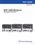
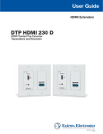
1
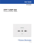
User Guide
Speakers
SF 26X
SpeedMount® Ceiling Mount Speakers
68-2222-01 Rev. A
12 13
Safety Instructions
Safety Instructions • English
WARNING: This symbol,
, when used on the product, is intended to
alert the user of the presence of uninsulated dangerous voltage within
the product’s enclosure that may present a risk of electric shock.
ATTENTION: This symbol,
, when used on the product, is intended
to alert the user of important operating and maintenance (servicing)
instructions in the literature provided with the equipment.
For information on safety guidelines, regulatory compliances, EMI/EMF
compatibility, accessibility, and related topics, see the Extron Safety and
Regulatory Compliance Guide, part number 68-290-01, on the Extron website,
www.extron.com.
Instructions de sécurité • Français
avertissement : Ce pictogramme,
, lorsqu’il est utilisé sur le
produit, signale à l’utilisateur la présence à l’intérieur du boîtier du
produit d’une tension électrique dangereuse susceptible de provoquer
un choc électrique.
attention :Ce pictogramme,
, lorsqu’il est utilisé sur le produit,
signale à l’utilisateur des instructions d’utilisation ou de maintenance
importantes qui se trouvent dans la documentation fournie avec le
matériel.
Pour en savoir plus sur les règles de sécurité, la conformité à la réglementation,
la compatibilité EMI/EMF, l’accessibilité, et autres sujets connexes, lisez les
informations de sécurité et de conformité Extron, réf. 68-290-01, sur le site
Extron, www.extron.com.
Sicherheitsanweisungen • Deutsch
warnung: Dieses Symbol
auf dem Produkt soll den Benutzer
darauf aufmerksam machen, dass im Inneren des Gehäuses dieses
Produktes gefährliche Spannungen herrschen, die nicht isoliert sind
und die einen elektrischen Schlag verursachen können.
Vorsicht: Dieses Symbol
auf dem Produkt soll dem Benutzer in der
im Lieferumfang enthaltenen Dokumentation besonders wichtige Hinweise
zur Bedienung und Wartung (Instandhaltung) geben.
Weitere Informationen über die Sicherheitsrichtlinien, Produkthandhabung,
EMI/EMF-Kompatibilität, Zugänglichkeit und verwandte Themen finden Sie in
den Extron-Richtlinien für Sicherheit und Handhabung (Artikelnummer
68-290-01) auf der Extron-Website, www.extron.com.
Instrucciones de seguridad • Español
ADVERTENCIA: Este símbolo,
, cuando se utiliza en el producto,
avisa al usuario de la presencia de voltaje peligroso sin aislar dentro del
producto, lo que puede representar un riesgo de descarga eléctrica.
ATENCIÓN: Este símbolo,
, cuando se utiliza en el producto, avisa
al usuario de la presencia de importantes instrucciones de uso y
mantenimiento recogidas en la documentación proporcionada con el
equipo.
Para obtener información sobre directrices de seguridad, cumplimiento
de normativas, compatibilidad electromagnética, accesibilidad y temas
relacionados, consulte la Guía de cumplimiento de normativas y seguridad de
Extron, referencia 68-290-01, en el sitio Web de Extron,www.extron.com.
Инструкция по технике безопасности • Русский
ПРЕДУПРЕЖДЕНИЕ: Данный символ,
, если указан
на продукте, предупреждает пользователя о наличии
неизолированного опасного напряжения внутри корпуса
продукта, которое может привести к поражению
электрическим током.
ВНИМАНИЕ: Данный символ,
, если указан на продукте,
предупреждает пользователя о наличии важных инструкций
по эксплуатации и обслуживанию в руководстве,
прилагаемом к данному оборудованию.
Для получения информации о правилах техники безопасности,
соблюдении нормативных требований, электромагнитной
совместимости (ЭМП/ЭДС), возможности доступа и других
вопросах см. руководство по безопасности и соблюдению
нормативных требований Extron на сайте Extron: www.extron.com,
номер по каталогу - 68-290-01.
Chinese Simplified(简体中文)
警告:
产品上的这个标志意在警告用户该产品机壳内有暴露的危险 电压,
有触电危险。
注 意:
产 品 上 的 这个 标 志 意 在 提 示用 户 设 备 随 附 的 用 户 手 册 中 有
重要的操作和维护(维修)说明。
关于我们产品的安全指南、遵循的规范、EMI/EMF 的兼容性、无障碍
使用的特性等相关内容,敬请访问 Extron 网站 www.extron.com,参见
Extron 安全规范指南,产品编号 68-290-01。
Chinese Traditional(
)
警告:
若產品上使用此符號,是為了提醒使用者,產品機殼內存在著
可能會導致觸電之風險的未絕緣危險電壓。
注意
若產品上使用此符號,是為了提醒使用者,設備隨附的用戶手冊中有重
要的操作和維護(維修)説明。
有關安全性指導方針、法規遵守、EMI/EMF 相容性、存取範圍和相關主題的詳細資
訊,請瀏覽 Extron 網站:www.extron.com,然後參閱《Extron 安全性與法規
遵守手冊》,準則編號 68-290-01。
Japanese
警告: この記号
が製品上に表示されている場合は、筐体内に絶縁されて
いない高電圧が流れ、感電の危険があることを示しています。
注意: この記号
が製品上に表示されている場合は、本機の取扱説明書
に 記載されている重要な操作と保守(整備)の指示についてユーザーの 注
意を喚起するものです。
安全上のご注意、法規厳守、EMI/EMF適合性、その他の関連項目に
ついては、エクストロンのウェブサイト www.extron.com より『Extron Safety
and Regulatory Compliance Guide』(P/N 68-290-01) をご覧ください。
Korean
경고: 이 기호
가 제품에 사용될 경우, 제품의 인클로저 내에 있는
접지되지 않은 위험한 전류로 인해 사용자가 감전될 위험이 있음을
경고합니다.
주의: 이 기호
가 제품에 사용될 경우, 장비와 함께 제공된 책자에 나와
있는 주요 운영 및 유지보수(정비) 지침을 경고합니다.
안전 가이드라인, 규제 준수, EMI/EMF 호환성, 접근성, 그리고 관련 항목에
대한 자세한 내용은 Extron 웹 사이트(www.extron.com)의 Extron 안전 및
규제 준수 안내서, 68-290-01 조항을 참조하십시오.
Conventions Used in this Guide
Notifications
The following notifications are used in this guide:
CAUTION: A caution indicates a situation that may result in minor injury.
WARNING: A warning indicates a situation that has the potential to result in death or
severe injury.
ATTENTION: Attention indicates a situation that may damage or destroy the product or
associated equipment.
NOTE: A note draws attention to important information.
Specifications Availability
Product specifications are available on the Extron website, www.extron.com.
Copyright
© 2013 Extron Electronics. All rights reserved.
Trademarks
All trademarks mentioned in this guide are the properties of their respective owners.
The following registered trademarks®, registered service marks(SM), and trademarks(TM) are the property of
RGB Systems, Inc. or Extron Electronics:
Registered Trademarks (®)
AVTrac, Cable Cubby, CrossPoint, eBUS, EDID Manager, EDID Minder, Extron, Flat Field, GlobalViewer, Hideaway, Inline, IP Intercom, IP Link,
Key Minder, LockIt, MediaLink, PlenumVault, PoleVault, PowerCage, PURE3, Quantum, SoundField, SpeedMount, SpeedSwitch,
System INTEGRATOR, TeamWork, TouchLink, V‑Lock, VersaTools, VN‑Matrix, VoiceLift, WallVault, WindoWall, XTP, and XTP Systems
Registered Service Mark(SM) : S3 Service Support Solutions
Trademarks (™)
AAP, AFL (Accu‑Rate Frame Lock), ADSP (Advanced Digital Sync Processing), AIS (Advanced Instruction Set), Auto‑Image, CDRS (Class D
Ripple Suppression), DDSP (Digital Display Sync Processing), DMI (Dynamic Motion Interpolation), Driver Configurator, DSP Configurator, DSVP
(Digital Sync Validation Processing), FastBite, FOXBOX, IP Intercom HelpDesk, MAAP, MicroDigital, ProDSP, QS-FPC (QuickSwitch Front Panel
Controller), Scope‑Trigger, SIS, Simple Instruction Set, Skew‑Free, SpeedNav, Triple‑Action Switching, XTRA, ZipCaddy, ZipClip
Contents
Introduction..................................................... 1
About the SF 26X Speaker ................................. 1
Features.............................................................. 1
Application Example............................................ 2
Installation....................................................... 3
Installing the SF 26X in a Suspended Ceiling....... 3
Painting the Baffle and Grille.............................. 12
SF 26X User Guide • Contents
iv
Introduction
This user guide contains information about the Extron SF 26X Ceiling Mount Speaker.
About the SF 26X Speaker
The SF 26X speaker is a two-way, low impedance, ceiling-mount speaker system that
features an 8 ohm open back speaker with a 6.5 inch woofer and a 3/4 inch tweeter
designed for use in non-plenum airspace environments.
Features
•
Open back, infinite baffle design
•
8 ohm nominal impedance
•
3/4" (1.9 cm) pivoting ferrofluid-cooled dome tweeter
•
6.5" (16.5 cm) polypropylene woofer
•
Frequency range: 50 Hz to 20 kHz
•
25 watts continuous pink noise, 50 watts continuous program
•
110° conical dispersion
•
Internal driver overload protection
•
Thin bezel and magnetically attached grille
•
Spring-loaded locking arms for quick ceiling installation
•
Optional Ceiling Mount Kit available for use with ceiling tiles, includes C-rings
and V-rails
•
Four pole captive screw connector simplifies parallel speaker wiring
•
Grille and bezel are available in white only and may be painted to match the
environment
•
5-year parts and labor warranty
SF 26X User Guide • Introduction
1
Application Example
The illustration below is one example of configuring a system using the SF 26X speakers.
Extron
TLP 1000TV
10" Tabletop
TouchLink
Touchpanel
Extron
DTP HDMI 230 Tx
SIG
INPUTS
POWER
12V
0.7A MAX
Laptop
LINK
AUDIO
OVER DTP
RS-232
Audio
DTP OUT
IR
Tx Rx G Tx Rx
Ethernet
CATx Cable
up to 230' (70 m)
HDMI
TCP/IP
Network
Ethernet
Transmitter
Extron
IPL 250
Control
Processor
STANDBY/ON
PQLS
HDMI
OPEN/CLOSE
FL OFF
Microphone
USB
Blu-ray Player
HDMI
POWER
12V
500mA
MAX
RS-232
COM 2
Tx Rx
INPUT
2 3 4
COM 3
Tx Rx
1
IR
2
RELAY
1
2
S G S G
1
3
IR
4
RELAY
3
4
S G S G
RS-232
WiFi
1 2 3 4
Audio
COM1
Tx Rx
RTS CTS
LAN
OVER DTP
OVER DTP
RS-232
DTP IN
SIG
LINK
IR
Tx Rx G Tx Rx
HDMI
L
1
R
L
2
R
L
L
4
R
L
5
R
MIC LINE
3
R
DTP OUT
PHANTOM POWER
LINK
5
50/60 Hz
SELECT
Tx Rx G Tx Rx
6
SIG
3
IR
OUTPUTS
4
RGB OUT
2
MUTE HDMI AUDIO
RS-232
1
AUDIO IN
X.XA MAX
INPUTS
100-240V
AUDIO OUT
Audio
VGA
Rack PC
L
MIC
MIX
PROGRAM
MPS 602 SA
R
AMP OUT
REMOTE
8Ω / 4Ω
L
L
FIXED
R
RS-232
R
CLASS 2 WIRING
R
Tx Rx G
Extron
MPS 602 SA
Switcher
Control
Media Presentation
Switcher
AV Device
Control
CATx Cable
up to 230' (70 m)
Audio
Extron
DTP HDMI 230 Rx
Receiver
OVER DTP
RS-232
IR
Tx Rx G Tx Rx
POWER
12V
0.7A MAX
SIG
LINK
DTP HDMI 230 Rx
OUTPUTS
L
AUDIO
R
DTP IN
RS-232
Projector
Figure 1.
HDMI
Extron
SF 26X
Two-Way Open Back 8 Ohm
Ceiling Speakers
SF 26X Application Example
SF 26X User Guide • Introduction
2
Installation
The Installation section describes:
•
Installing the SF 26X in a Suspended Ceiling
•
Painting the Baffle and Grille
Installing the SF 26X in a Suspended Ceiling
1. Remove power from all devices.
NOTE: If the baffle or grille is to be painted, see the Painting the Baffle and Grille
section on page 12.
The maximum ceiling tile thickness that the speaker can go into is 1.22 inches (31 mm).
2. Cut a hole for the SF 26X. Use the provided cutout template to outline the hole to be
cut in the ceiling tile, as described below.
a. Remove the ceiling tile and use the provided cutout template to outline the hole to
be cut in the tile.
NOTE: If the baffle and grille will be painted, save the cutout template as a paint
shield.
b. Cut out the circle traced in the ceiling tile.
c. Replace the ceiling tile into the ceiling.
3. Install the optional SF 26X ceiling mount kit.
a. Attach two V-rails and one C-ring across the tile above the hole cut in step 2 above.
b. See the illustration below.
C-ring
V-rail
Figure 2.
Installing the V-rails and C-ring
4. Route the speaker wires through the ceiling tile hole.
5. Remove the grille carefully from the SF 26X.
NOTE: Grille hooks are provided for grille removal, if needed.
SF 26X User Guide • Installation
3
6. Attach speaker wires from the ceiling tile hole to the included four-pole captive screw
connector using one of the following three methods below.
NOTES:
• Be sure that the combined impedance of the speaker system does not equal a
value less than the rated minimum load impedance of the
amplifier.
• The maximum number of wires per terminal are as follows:
Wire Gauge Table
Number of Wires per
Connection Point
Maximum
Wire Gauge
1
12 AWG
2
16 AWG
• Do not tin the wires. Tinned wires do not hold tight in the captive screws and
can break easily after several bends.
• Strip no more than 3/16" (5 mm) of insulation from the end of the wire before
inserting it into the captive screw connector.
Do not tin the wires!
SF 26X User Guide • Installation
4
Wiring Multiple Speakers Using Loop-through:
A loop-through electrical connection is made on the crossover board of the
SF 26X. Connect the wires to the captive screw connectors of the speakers, as
shown below. Be sure to tighten the screws.
NOTES:
• Be sure that the combined impedance of the speaker system does not
equal a value less than the rated minimum load impedance of the
amplifier.
• When a chain of speakers is wired in this configuration, disconnecting one
speaker removes power from the remaining speaker in the chain.
(Red)
(Red)
(Black)
_
_
+
Power Amplifier
_
+
+
+
(Black)
_
•
Speaker 2
Speaker 1
This configuration is useful for troubleshooting in four ways:
•
The system is sectioned for easier troubleshooting.
•
The source signal can be tested by connecting to the inner + (IN) and inner
– (IN) terminals of the captive screw connector, as shown below.
Red Wire (+) from Amplifier
Amplifier
Black Wire (-) from Amplifier
Test Points
__
++
Captive Screw
Connector
Signal Test Points
SF 26X User Guide • Installation
5
•
To test the impedance of the entire speaker system, first disconnect the
speaker wires from the amplifier and then measure the impedance from the
disconnected wires, as shown below.
Amplifier
Red Wire (+) disconnected
from Amplifier
Test Points
To next speaker
Black Wire (-) disconnected
from Amplifier
__
++
Captive Screw
Connector
Impedance Test Points
ATTENTION: Disconnect the speaker system from the amplifier before
performing this test, otherwise you may damage the test meter.
•
The impedance of the speaker downstream of the one being tested can be
measured while the system is powered on by first disconnecting the captive
screw connector from the speaker being tested and then connecting the test
probes to the outer (LOOP) terminals of the connector, as shown below.
ATTENTION: Be certain to first disconnect the captive screw connector
from the speaker being tested and test the outer (LOOP) terminals,
otherwise you may damage the test meter.
Red Wire (+) from Amplifier
Amplifier
To next speaker
Black Wire (-) from Amplifier
Test Points
__
++
Captive Screw
Connector
Impedance Test Points
SF 26X User Guide • Installation
6
Wiring Speakers in Parallel:
Connect the wires to the captive screw connectors of the speakers, as shown
below. Be sure to tighten the screws.
NOTES:
• Be sure that the combined impedance of the speaker system does not
equal a value less than the rated minimum load impedance of the
amplifier.
• When a chain of speakers is wired in this configuration, disconnecting one
speaker does not remove power from the remaining speaker in the chain.
(Red)
(Red)
(Black)
_
+
+
_
_
+
Power Amplifier
+
(Black)
_
•
Speaker 1
Speaker 2
This configuration is especially useful in installations where the system can never be
completely down, such as in a hospital setting.
The source signal can be tested by connecting to the inner + (IN) and inner – (IN)
terminals of the captive screw connector, as shown below.
Red Wire (+) from Amplifier
Amplifier
Black Wire (-) from Amplifier
Test Points
__
++
Captive Screw
Connector
Signal Test Points
SF 26X User Guide • Installation
7
To test the impedance of the entire speaker system, first disconnect the speaker
wires from the amplifier and then measure the impedance from the disconnected
wires, as shown below.
Amplifier
Red Wire (+) disconnected
from Amplifier
Test Points
To next speaker
Black Wire (-) disconnected
from Amplifier
__
++
Captive Screw
Connector
Impedance Test Points
ATTENTION: Disconnect the speaker system from the amplifier before
performing this test, otherwise you may damage the test meter.
Wiring a Single Speaker:
Connect the wires to the captive screw connector of the speaker, as shown below.
Be sure to tighten the screws.
(Red)
_
+
+
(Black)
Power Amplifier
_
•
Speaker 1
SF 26X User Guide • Installation
8
7. Insert the captive screw connector into the four-pole receptacle on the speaker
crossover board as shown below.
Strain Relief
Tie off Point
Zip Tie
Captive Screw
Connector
Figure 3.
Strain Relief Tie Off Point
8. Secure the speaker wire to the strain relief tie off point using the included zip tie as
shown above.
9. Mount the SF 26X.
a. Insert the SF 26X through the bottom of the hole in the ceiling tile that was cut in
step 2.
b. Tighten the four screws (clockwise) of the locking arms until the arms are fully
engaged and the speaker is securely clamped to the ceiling, as shown below.
ATTENTION: Do not overtighten the screws.
Speaker Grille
Locking Arm
Figure 4.
Mounting the Speaker Using the Four Locking Arms
SF 26X User Guide • Installation
9
10. Attach the secondary support line if required, as shown below.
Secondary
Support Line
Figure 5.
Secondary
Tie off Point
Attaching the Secondary Support Line
a. Remove the ceiling tile adjacent to the tile where the speaker is mounted.
b. Attach the secondary support line.
ATTENTION: Do not allow any slack in the secondary support line.
c. Replace the adjacent ceiling tile.
11. Pivot the tweeter to aim the mid and high frequencies to the desired spot, as shown
below.
Figure 6.
Pivoting the Tweeter
ATTENTION: The tweeter can be pivoted only. Do not attempt to rotate the
tweeter.
SF 26X User Guide • Installation
10
12. Position the outer perimeter of the grille into the groove of the speaker baffle. Six
magnets pull the grille securely into place, as shown below.
Speaker Grille
Figure 7.
Installing the SF 26X Grille
NOTE: Grille hooks are provided for removal of the grille after installation.
SF 26X User Guide • Installation
11
Painting the Baffle and Grille
NOTE: The cutout template that was used in step 2 of the previous section will be used
as a paint shield when painting the outer circumference of the baffle.
Painting the Baffle
1. Remove the grille using the provided grille hooks and set the grille aside.
2. Place cutout template over the center of the tweeter so that the woofer and tweeter of
the speaker are protected from the paint.
3. Tape over the center hole of the template to prevent any paint from entering the hole.
4. Tape over any exposed portion of the baffle that is normally covered by the grille. This
includes the perimeter outside of the template where the grille magnets are located.
ATTENTION: Do not allow paint to touch the magnets, otherwise the grille
installation will not be as secure. Do not allow paint to enter the baffle groove
where the grille will reside, otherwise the grille may not contact the magnets
properly for a secure fit.
5. Clean the outer perimeter of the baffle to be painted with a damp cloth.
6. Paint the outer baffle.
Painting the Grille
1. With the grille detached from the speaker, carefully remove the scrim from the inner side
of the grille.
2. Carefully remove the Extron logo from the front of the grille.
3. Clean the outside of the grille surface with a damp cloth.
4. Carefully spray paint the outside surface of the grille.
ATTENTION: Be sure to keep the paint from clogging the grille perforations,
otherwise the speaker output will be affected.
5. After the paint has completely dried, reattach the logo and scrim.
SF 26X User Guide • Installation
12
Extron Warranty
Extron Electronics warrants this product against defects in materials and workmanship for a period of five years
from the date of purchase. In the event of malfunction during the warranty period attributable directly to faulty
workmanship and/or materials, Extron Electronics will, at its option, repair or replace said products or components,
to whatever extent it shall deem necessary to restore said product to proper operating condition, provided that it is
returned within the warranty period, with proof of purchase and description of malfunction to:
USA, Canada, South America,
and Central America:
Extron Electronics
1230 South Lewis Street
Anaheim, CA 92805
U.S.A.
Japan:
Extron Electronics, Japan
Kyodo Building, 16 Ichibancho
Chiyoda-ku, Tokyo 102-0082
Japan
Europe and Africa:
Extron Europe
Hanzeboulevard 10
3825 PH Amersfoort
The Netherlands
China:
Extron China
686 Ronghua Road
Songjiang District
Shanghai 201611
China
Asia:
Extron Asia Pte Ltd
135 Joo Seng Road, #04-01
PM Industrial Bldg.
Singapore 368363
Singapore
Middle East:
Extron Middle East
Dubai Airport Free Zone
F12, PO Box 293666
United Arab Emirates, Dubai
This Limited Warranty does not apply if the fault has been caused by misuse, improper handling care, electrical
or mechanical abuse, abnormal operating conditions, or if modifications were made to the product that were not
authorized by Extron.
NOTE: If a product is defective, please call Extron and ask for an Application Engineer to receive an RA (Return
Authorization) number. This will begin the repair process.
USA:
Asia:
714.491.1500 or 800.633.9876
65.6383.4400
Europe:
Japan:
31.33.453.4040
81.3.3511.7655
Units must be returned insured, with shipping charges prepaid. If not insured, you assume the risk of loss or damage
during shipment. Returned units must include the serial number and a description of the problem, as well as the
name of the person to contact in case there are any questions.
Extron Electronics makes no further warranties either expressed or implied with respect to the product and its quality,
performance, merchantability, or fitness for any particular use. In no event will Extron Electronics be liable for direct,
indirect, or consequential damages resulting from any defect in this product even if Extron Electronics has been
advised of such damage.
Please note that laws vary from state to state and country to country, and that some provisions of this warranty may
not apply to you.
Extron Headquarters
+1.800.633.9876 (Inside USA/Canada Only)
Extron USA - West
Extron USA - East
+1.714.491.1500+1.919.850.1000
+1.714.491.1517 FAX
+1.919.850.1001 FAX
Extron Europe
+800.3987.6673
(Inside Europe Only)
+31.33.453.4040
+31.33.453.4050 FAX
Extron Asia
+65.6383.4400
+65.6383.4664 FAX
Extron Japan
+81.3.3511.7655
+81.3.3511.7656 FAX
© 2013 Extron Electronics All rights reserved.
Extron China
+86.21.3760.1568
+86.21.3760.1566 FAX
Extron Middle East
+971.4.299.1800
+971.4.299.1880 FAX
www.extron.com
Extron Korea
+82.2.3444.1571
+82.2.3444.1575 FAX
Extron India
1800.3070.3777
(Inside India Only)
+91.80.3055.3777
+91.80.3055.3737 FAX