1
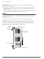
Supplying Power to the Alpine 3802 DC Power Supply
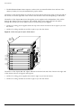
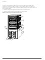
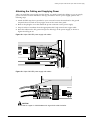
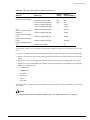
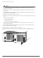
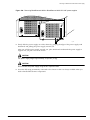
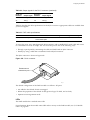
6 Replace the plexiglas cover.
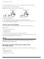
7 Turn on the DC supply at both the wall breaker and at the power supply breaker.
8 Leave the ESD strap permanently connected to the chassis so that it is always available when you
need to handle ESD-sensitive components.
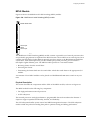
Verifying a Successful Installation
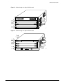
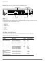
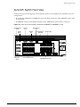
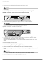
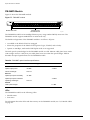
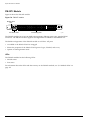
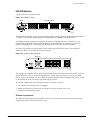
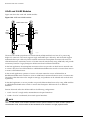
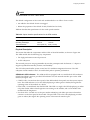
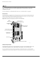
After you supply power to the Alpine switch, the switch performs a power-on self test (POST).
During the POST:
• All ports are temporarily disabled
• The packet LED is off
• The power LED is on
• The MGMT LED flashes until the switch successfully passes the POST
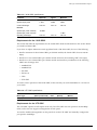
If the switch passes the POST, the MGMT LED blinks at a slow rate (one blink per second). If the switch
fails the POST, the MGMT LED shows a solid yellow light.
NOTE
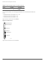
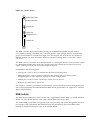
See Chapter 9, “Alpine 3800 Series Switch Management Module” for more information about switch
management module LED activity and Chapter 10, “Alpine 3800 Series I/O Modules” for more
information about I/O module LED activity.
Extreme Networks Consolidated Hardware Guide
143