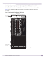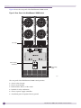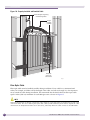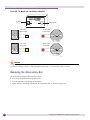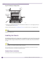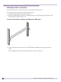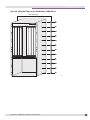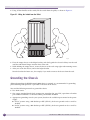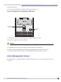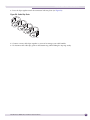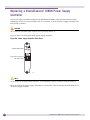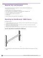
1
BlackDiamond® 10808 Switch
Hardware Installation Guide
Extreme Networks, Inc.
3585 Monroe Street
Santa Clara, California 95051
(888) 257-3000
(408) 579-2800
http://www.extremenetworks.com
Published: September 2009
Part number: 100285-00 Rev. 02
AccessAdapt, Alpine, Altitude, BlackDiamond, EPICenter, ExtremeWorks Essentials, Ethernet Everywhere, Extreme
Enabled, Extreme Ethernet Everywhere, Extreme Networks, Extreme Standby Router Protocol, Extreme Turbodrive,
Extreme Velocity, ExtremeWare, ExtremeWorks, ExtremeXOS, Go Purple Extreme Solution, ExtremeXOS ScreenPlay,
ReachNXT, Sentriant, ServiceWatch, Summit, SummitStack, Triumph, Unified Access Architecture, Unified Access
RF Manager, UniStack, the Extreme Networks logo, the Alpine logo, the BlackDiamond logo, the Extreme
Turbodrive logo, the Summit logos, and the Powered by ExtremeXOS logo are trademarks or registered trademarks
of Extreme Networks, Inc. or its subsidiaries in the United States and/or other countries.
sFlow is a registered trademark of InMon Corporation.
Specifications are subject to change without notice.
All other registered trademarks, trademarks, and service marks are property of their respective owners.
© 2008, 2009 Extreme Networks, Inc. All Rights Reserved.
For safety compliance information, see Appendix A, “Safety Information.”
2
BlackDiamond 10808 Switch Hardware Installation Guide
Table of Contents
Preface........................................................................................................................................... 7
Introduction ...............................................................................................................................7
Conventions................................................................................................................................8
Related Publications ...................................................................................................................8
Part 1: About the BlackDiamond 10808 Switch
Chapter 1: Overview of the BlackDiamond 10808 Switch................................................................. 13
Overview of the BlackDiamond 10808 Switch..............................................................................13
Full-Duplex Support ..................................................................................................................13
Management Ports ....................................................................................................................14
External Compact Flash Memory Card .........................................................................................14
BlackDiamond 10808 Switch Chassis.........................................................................................14
Chapter 2: BlackDiamond 10808 Series Modules ........................................................................... 17
Overview of the BlackDiamond 10808 Modules ...........................................................................17
Management Switch Modules (MSMs).........................................................................................17
Redundant MSM Activity .....................................................................................................18
MSM Physical Features........................................................................................................18
MSM LEDs .........................................................................................................................19
I/O Modules..............................................................................................................................20
G60T Module .....................................................................................................................21
G60T LEDs...................................................................................................................21
G60X Module .....................................................................................................................22
SFP (Mini-GBIC) Ports ...................................................................................................22
G60X LEDs...................................................................................................................23
G20X Module .....................................................................................................................23
SFP Ports .....................................................................................................................24
G20X LEDs...................................................................................................................24
10G6X Module ...................................................................................................................24
XENPAK Ports ..............................................................................................................25
10G6X LEDs.................................................................................................................25
10G2X Module ...................................................................................................................26
XENPAK Ports ..............................................................................................................26
10G2X LEDs.................................................................................................................27
10G2H Module ...................................................................................................................27
XENPAK Ports ..............................................................................................................28
SFP Ports .....................................................................................................................28
10G2H LEDs ................................................................................................................28
I/O Module LEDs .................................................................................................................29
Chapter 3: Power Supply Units for the BlackDiamond 10808 Switch ................................................ 31
Overview of BlackDiamond 10808 Power Supplies .......................................................................31
Extreme Networks 700/1200 W AC PSU .....................................................................................31
BlackDiamond 10808 Switch Hardware Installation Guide
3
Table of Contents
LEDs..................................................................................................................................32
Power Supply Cords.............................................................................................................32
Fuse ..................................................................................................................................33
Specifications .....................................................................................................................33
Extreme Networks 1200 W DC PSU ............................................................................................34
Minimum Software Required ................................................................................................35
LEDs..................................................................................................................................35
Part 2: Installing BlackDiamond 10808 Hardware
Chapter 4: Site Preparation............................................................................................................ 39
Planning Your Site ....................................................................................................................39
Meeting Site Requirements ........................................................................................................40
Operating Environment Requirements ...................................................................................40
Building and Electrical Codes.........................................................................................40
Wiring Closet Considerations ..........................................................................................41
Temperature .................................................................................................................41
Humidity ......................................................................................................................42
Chassis Spacing Requirements .......................................................................................42
Chassis Airflow Requirements.........................................................................................42
Electrostatic Discharge ..................................................................................................43
Rack Specifications and Recommendations ...........................................................................44
Mechanical Recommendations for the Rack .....................................................................44
Protective Grounding for the Rack...................................................................................44
Space Requirements for the Rack ...................................................................................45
Securing the Rack .........................................................................................................45
Evaluating and Meeting Cable Requirements ...............................................................................46
Cabling Standards ...............................................................................................................46
Cable Labeling and Record Keeping ......................................................................................46
Installing Cable...................................................................................................................47
Fiber Optic Cable ..........................................................................................................48
Cable Distances ............................................................................................................49
RJ-45 Connector Jackets .....................................................................................................50
Radio Frequency Interference...............................................................................................51
Meeting Power Requirements .....................................................................................................51
PoE Devices .......................................................................................................................51
Power Supply Requirements.................................................................................................51
AC Power Cord Requirements ...............................................................................................52
Uninterruptible Power Supply Requirements ..........................................................................52
Selecting a UPS ............................................................................................................53
Calculating Volt-Amperage Requirements.........................................................................53
UPS Transition Time .....................................................................................................53
Applicable Industry Standards....................................................................................................53
Chapter 5: Installing a BlackDiamond 10808 Chassis ..................................................................... 55
Required Tools and Resources....................................................................................................56
Unpacking the Chassis ..............................................................................................................56
Checking the Shipping Status Indicators ...............................................................................56
Removing the Accessories Box..............................................................................................58
Removing the Carton from the Chassis ..................................................................................59
Installing the Chassis ................................................................................................................62
4
BlackDiamond 10808 Switch Hardware Installation Guide
Table of Contents
Standard Rack Installation ...................................................................................................62
Mid-Mount Rack Installation ................................................................................................66
Grounding the Chassis ...............................................................................................................68
Initial Management Access ........................................................................................................69
Chapter 6: Installing Power Supply Units in the BlackDiamond10808 Switch ................................... 71
Safety ......................................................................................................................................71
BlackDiamond PSU Compatibility ...............................................................................................72
Minimum Software Requirements ...............................................................................................72
Power Input Cords for the 700/1200 W AC PSU ..........................................................................72
Installing an Extreme Networks 700/1200 W AC PSU ..................................................................73
Required Tools and Equipment.............................................................................................73
Installing the 700/1200 W AC PSU ......................................................................................73
Removing or Replacing an Extreme Networks 700/1200 W AC PSU .........................................75
LEDs on the 700/1200 W AC PSU........................................................................................75
Installing an Extreme Networks 1200 W DC PSU .........................................................................76
Minimum Software Required ................................................................................................77
Pre-Installation Requirements ..............................................................................................77
Installing the DC Wiring .......................................................................................................77
Installing a 1200 W DC PSU ................................................................................................78
Removing an Extreme Networks 1200 W DC PSU...................................................................81
LEDs on the 1200 W DC PSU ..............................................................................................82
Chapter 7: Installing BlackDiamond 10808 Modules ....................................................................... 83
Module Slot Assignments...........................................................................................................83
Installing a BlackDiamond 10808 Series Module .........................................................................83
Making Network Interface Cable Connections...............................................................................86
Initial Management Access ........................................................................................................86
Connecting Equipment to the Console Port ............................................................................86
Logging In for the First Time ................................................................................................87
Installing a Backup MSM ...........................................................................................................87
Verifying the Module Installation ................................................................................................88
Displaying Slot Status Information ........................................................................................88
Removing a BlackDiamond 10808 Series Module ........................................................................88
Blank Front Panels ....................................................................................................................89
Installing a Blank Front Panel ..............................................................................................90
Removing a Blank Front Panel..............................................................................................90
Installing or Removing an External Compact Flash Memory Card....................................................91
Part 3: Installing BlackDiamond Switch Accessories
Chapter 8: BlackDiamond Cable Management ................................................................................. 95
About BlackDiamond Cable Management ....................................................................................95
Installing the BlackDiamond 10808 Cable Manager .....................................................................95
Using the Cable Holders and Cable Clips ...................................................................................100
Connecting Cable Holders ..................................................................................................101
Connecting Cable Clips ......................................................................................................102
BlackDiamond 10808 Switch Hardware Installation Guide
5
Table of Contents
Part 4: BlackDiamond Maintenance Procedures
Chapter 9: Replacing BlackDiamond 10808 Switch Chassis Components ....................................... 107
Replacing a BlackDiamond 10808 Switch Fan Tray ...................................................................107
Removing the Fan Tray ......................................................................................................107
Installing the Replacement Fan Tray ...................................................................................108
Replacing the BlackDiamond 10808 Air Filter ...........................................................................109
Replacing a BlackDiamond 10808 Power Supply Controller ........................................................110
Pre-Installation Requirements ............................................................................................111
Removing a Power Supply Controller ...................................................................................111
Installing a Power Supply Controller ....................................................................................112
Verifying a Successful Installation.......................................................................................112
Chapter 10: Repacking a BlackDiamond 10808 Chassis................................................................ 113
Safety Information ..................................................................................................................113
Required Tools and Equipment.................................................................................................114
Repacking the BlackDiamond 10808 Chassis ............................................................................114
Part 5: Appendices
Appendix A: Safety Information .................................................................................................... 121
Considerations Before Installing ...............................................................................................121
Installing Power Supply Units...................................................................................................122
Maintenance Safety.................................................................................................................123
General Safety Precautions ......................................................................................................123
Cable Routing for LAN Systems ..........................................................................................123
PoE Devices .....................................................................................................................124
Selecting Power Supply Cords ..................................................................................................124
Battery Replacement and Disposal............................................................................................125
Fiber Optic Ports—Optical Safety .............................................................................................126
GBIC, SFP (Mini-GBIC), XENPAK, and XFP Regulatory Compliance .......................................126
Sicherheitshinweise.................................................................................................................127
Hinweise zur Installation....................................................................................................127
Appendix B: Technical Specifications .......................................................................................... 133
BlackDiamond 10808 Switch...................................................................................................133
Power Supplies for the BlackDiamond 10808 Switch .................................................................135
Connector Pinouts ...................................................................................................................136
Index .......................................................................................................................................... 139
6
BlackDiamond 10808 Switch Hardware Installation Guide
Preface
This preface provides an overview of this guide, describes guide conventions, and lists other
publications that might be useful.
NOTE
Service to all equipment should be performed by trained and qualified service personnel only. Before installing or
removing any components of the system, or before carrying out any maintenance procedures, you must thoroughly
read the safety information provided in Appendix A of this guide. Failure to follow this safety information can lead to
personal injury or damage to the equipment.
Introduction
This guide describes how to install the Extreme Networks® BlackDiamond® 10808 switch. This guide
also contains information about site preparation, switch functionality, and switch operation.
This guide is intended for use by network administrators responsible for installing and setting up
network equipment. It assumes a basic working knowledge of:
●
Local area networks (LANs)
●
Ethernet concepts
●
Ethernet switching and bridging concepts
●
Routing concepts
●
Simple Network Management Protocol (SNMP)
See the ExtremeXOS 12.1 Concepts Guide and the ExtremeXOS 12.1 Command Reference Guide for
information about configuring Extreme Networks BlackDiamond 10808 switches.
NOTE
If the information in the installation note or release note shipped with your Extreme Networks switch differs from the
information in this guide, follow the installation or release note.
BlackDiamond 10808 Switch Hardware Installation Guide
7
Preface
Conventions
Table 1 and Table 2 list conventions used throughout this guide.
Table 1: Notice Icons
Icon
Notice Type
Alerts you to...
Note
Important features or instructions.
Caution
Risk of personal injury, system damage, or loss of data.
Warning
Risk of severe personal injury.
Table 2: Text Conventions
Convention
Description
Screen displays
This typeface represents information as it appears on the screen, or command
syntax.
The words “enter”
and “type”
When you see the word “enter” in this guide, you must type something, and then
press the Return or Enter key. Do not press the Return or Enter key when an
instruction simply says “type.”
[Key] names
Key names appear in text in one of two ways:
• Referenced by their labels, such as “the Return key” or “the Escape key”
• Written with brackets, such as [Return] or [Esc]
If you must press two or more keys simultaneously, the key names are linked with a
plus sign (+). Example:
Press [Ctrl]+[Alt]+[Del].
Words in italicized type
Italics emphasize a point of information or denote new terms at the place where
they are defined in the text.
Related Publications
The Extreme Networks ExtremeXOS® switch documentation set includes:
8
●
ExtremeXOS Concepts Guide
●
ExtremeXOS Command Reference Guide
●
ExtremeXOS Release Notes
●
BlackDiamond 8800 Series Switches Hardware Installation Guide
●
BlackDiamond 12800 Series Switches Hardware Installation Guide
●
BlackDiamond 20800 Series Switches Hardware Installation Guide
●
Summit Family Switches Hardware Installation Guide
●
Extreme Networks Pluggable Interface Modules Installation Guide
BlackDiamond 10808 Switch Hardware Installation Guide
Related Publications
Documentation for Extreme Networks products is available from the Extreme Networks website at the
following location:
http://www.extremenetworks.com/go/documentation
You can select and download the following Extreme Networks documentation from the Documentation
Overview page:
●
Software User Guides
●
Hardware User Guides
You can find archived user guides for software at:
http://www.extremenetworks.com/services/documentation/swuserguides.asp
You can also find archived installation guides for hardware at:
http://www.extremenetworks.com/services/documentation/hwuserguides.asp
BlackDiamond 10808 Switch Hardware Installation Guide
9
Preface
10
BlackDiamond 10808 Switch Hardware Installation Guide
1
About the BlackDiamond 10808 Switch
1
Overview of the BlackDiamond 10808 Switch
This chapter describes the Extreme Networks BlackDiamond 10808 switch and includes the following
sections:
●
Overview of the BlackDiamond 10808 Switch on page 13
●
Full-Duplex Support on page 13
●
Management Ports on page 14
●
External Compact Flash Memory Card on page 14
●
BlackDiamond 10808 Switch Chassis on page 14
For information about the I/O modules and management modules (MSMs) for the BlackDiamond 10808
switch, see Chapter 3, “BlackDiamond 10808 Series Modules.”.
For information about installing the BlackDiamond 10808 switch, see Chapter 3.
Overview of the BlackDiamond 10808 Switch
The BlackDiamond 10808 switch is a chassis-based, Ethernet service core switch designed for core
applications.
The features of this switch include:
●
Hot-swappable I/O modules that include Gigabit Ethernet copper ports (10/100/1000) and Gigabit
Ethernet fiber ports (SFP), or 10 Gigabit Ethernet ports (XFP)
●
Management Switch Fabric Modules (MSMs) that provide the active switching fabric and CPU
control subsystem
●
Redundant, load-sharing, hot-swappable power supplies
●
Field-replaceable, hot-swappable fan trays
●
Auto-negotiation for half-duplex or full-duplex operation on 10/100/1000 Mbps ports
●
Load sharing on multiple ports
For more information about configuring a BlackDiamond switch, see the ExtremeXOS 12.1 Concepts
Guide and the ExtremeXOS 12.1 Command Reference Guide.
Full-Duplex Support
Extreme Networks switches provide full-duplex support for all ports. Full-duplex support means that
frames can be transmitted and received simultaneously, which, in effect, doubles the bandwidth
available on a link. Most ports on an Extreme Networks switch will auto-negotiate duplex in the default
configuration. Gigabit Ethernet fiber ports and 10-gigabit Ethernet ports operate only in full-duplex
mode in accordance with technical standards.
BlackDiamond 10808 Switch Hardware Installation Guide
13
Overview of the BlackDiamond 10808 Switch
Management Ports
Each BlackDiamond series Management Switch Fabric Module (MSM) has a 10/100BASE-TX Ethernet
management port. This port allows you to communicate directly with the central processing unit (CPU)
of the switch. You can plug an Ethernet cable directly from your laptop into the management port, for
direct access into the switch. This access allows you to view and locally manage the switch
configurations.
External Compact Flash Memory Card
All MSMs in the BlackDiamond family include a compact flash slot next to the console port on the
MSM. This slot accepts a compact flash memory card, which can be used to download a new version of
ExtremeXOS and for other functions, including capturing debug information and core dump files. See
the ExtremeXOS 12.1 Concepts Guide for more information regarding the use of the external compact
flash memory card.
The external compact flash slot supports third-party compact flash cards.
NOTE
You must use an industrial-grade compact flash card in the external compact flash slot of the MSM.
BlackDiamond 10808 Switch Chassis
The BlackDiamond 10808 switch chassis includes the following components:
●
One 10-slot chassis with backplane
●
Eight I/O module slots, labeled 1 through 8
●
Two MSM slots, labeled A and B
●
Up to six power supplies, accessed from the front of the unit)
●
Two hot-swappable fan trays, accessed from the back of the unit. Each fan tray contains two fans.
●
One connector for an ESD-preventive wrist strap
Software monitors the fan trays in the BlackDiamond 10808 switch for overheating. All
over-temperature events cause the switch to send alerts to the network management station or to the
switch log. See the ExtremeXOS 12.1 Concepts Guide for more information about switch monitoring.
CAUTION
Do not cover or obstruct the fan ventilation holes at the rear of the unit. Doing so can result in overheating and
possible damage to the BlackDiamond 10808 switch. Thermal sensors will shut down the BlackDiamond 10808
switch if the internal temperature exceeds 60 degrees Celsius.
The BlackDiamond 10808 switch includes two power supply controllers, located in the back of the
chassis, that collect data from the installed power supplies and report the results to the MSM modules.
The power supply controllers provide primary/backup redundancy in case one of the controllers fails
or is removed. At least one power supply controller must be installed.
14
BlackDiamond 10808 Switch Hardware Installation Guide
BlackDiamond 10808 Switch Chassis
When the BlackDiamond 10808 switch is first powered on, the power supply controllers enable the
power supplies by providing 48V power. The power supply controller also detects and reports
incompatible combinations of power supply types and line voltage feeds and disables the power supply
if an unsafe condition arises.
Figure 1 shows a BlackDiamond 10808 switch equipped with two MSM-1 modules and eight optional
I/O modules.
Figure 1: Front View of the BlackDiamond 10808 Switch
I/O module slots
MSM module
slots
I/O module slots
ESD wrist strap
connector
Power supplies
behind grill
EX_001
BlackDiamond 10808 Switch Hardware Installation Guide
15
Overview of the BlackDiamond 10808 Switch
Figure 2 shows the rear panel of the BlackDiamond 10808 switch.
Figure 2: Rear View of the BlackDiamond 10808 Switch
Fan trays
Power supply
controllers
Grounding
point
EX_007A
The rear panel of the BlackDiamond 10808 switch provides:
16
●
Access to the fan units
●
Chassis serial number
●
Ethernet MAC address of the switch
●
Symbols of safety certification
●
Access to power supply controllers
●
Attachment point for optional chassis ground
BlackDiamond 10808 Switch Hardware Installation Guide
2
BlackDiamond 10808 Series Modules
This chapter describes the I/O modules and the Management Switch Module (MSM) that are installed
in the BlackDiamond 10808 switch chassis. The chapter includes the following sections:
●
Overview of the BlackDiamond 10808 Modules on page 17
●
Management Switch Modules (MSMs) on page 17
●
I/O Modules on page 20
For instructions on installing the BlackDiamond 10808 modules, see Chapter 5, “Installing
BlackDiamond 10808 Modules.”
Overview of the BlackDiamond 10808 Modules
Modules available for the BlackDiamond 10808 switch include management switch modules (MSMs)
and I/O modules. A BlackDiamond module consists of a printed circuit board mounted on a metal
panel that acts as the insertion vehicle in the BlackDiamond 10808 switch. The module carrier also
includes ejector/injector levers and captive retaining screws at each end of the module front panel.
LEDs on the module front panel provide information about the operating status of the modules.
Management Switch Modules (MSMs)
The BlackDiamond MSM holds the control plane and the switch fabric for the switch. In addition, each
MSM has two CPUs for protocol processing and network management. The BlackDiamond 10808
chassis has two slots for installing MSMs. Although the system will operate with a single MSM,
bandwidth is reduced. Two MSMs are required for full system bandwidth.
The following MSMs are available for the BlackDiamond 10808 switch:
●
MSM-1
●
MSM-1XL
The MSM-1 and MSM-1XL have different size Ternary Content Addressable Memory (TCAM). The
MSM-1XL has more memory available for routing tables, learned MAC addresses, and access control
lists (ACLs). For specific details about memory allocation, refer to the data sheet for each module.
MSMs are installed in designated lettered slots in the BlackDiamond 10808 chassis.
A compact flash slot allows you to insert an external compact flash memory card. (See “External
Compact Flash Memory Card” on page 14 for more information about Extreme Networks-supported
compact flash cards.).
BlackDiamond 10808 Switch Hardware Installation Guide
17
BlackDiamond 10808 Series Modules
Redundant MSM Activity
The BlackDiamond 10808 switch can operate with a single MSM installed. When you install a second
MSM, one of the MSMs operates as the primary, and the other becomes the backup.
The primary MSM is responsible for upper-layer protocol processing and system management
functions. For example, OSPF computation and SNMP functions are performed by the primary MSM.
Packet handling is distributed among the CPUs of all installed MSMs.
When you save the switch configuration, it is saved to all MSMs. If you download a new ExtremeXOS
image, the image is downloaded to all MSMs.
Selection of the primary MSM occurs automatically. The following examples describe the selection
process:
●
When the BlackDiamond 10808 switch boots with two MSMs already installed, the MSM in slot A
becomes the primary MSM.
●
When the BlackDiamond 10808 switch boots with a single MSM (regardless of the slot position), it is
selected as the primary MSM.
If a second MSM is added to the switch after it has been powered on, the added MSM becomes the
backup MSM. MSMs that operate as backups can be inserted and removed without disrupting
network services.
●
If you remove the primary MSM while the BlackDiamond 10808 switch is operating, the backup
MSM performs a soft reset and then becomes the primary MSM.
For example, in a BlackDiamond 10808 switch with a primary MSM in slot A and a backup MSM in
slot B, if you remove the primary MSM from slot A, the backup MSM in slot B becomes the primary
MSM.
MSM Physical Features
Figure 3 shows the front panel of the BlackDiamond 10808 series MSM.
Figure 3: BlackDiamond 10808 Series MSM
Module status LEDs
Module reset button
Management port
Console port
Compact flash
EX_003
18
BlackDiamond 10808 Switch Hardware Installation Guide
Management Switch Modules (MSMs)
The BlackDiamond 10808 MSMs have the following features on the front panel:
●
LEDs to indicate module operating status
●
Module reset button—Allows you to reset the MSM without removing the module from the chassis.
●
Management port—Used to connect an Ethernet cable directly from your laptop into the
management port to view and locally manage the switch configurations. This port can also be used
to connect the system into a parallel management network for administration.
●
Console port—Used to connect a terminal and perform local management.
●
Compact flash slot
MSM LEDs
Table 3 describes the LED activity on the BlackDiamond 10808 MSM.
Table 3: MSM LEDs
LED
Color
Indicates
SYS
Green blinking
Module is operating normally.
Amber blinking
Diagnostic test is in progress.
Amber
Diagnostic failure has occurred.
Off
Switch is not receiving power.
Green
Module is operating as primary.
Amber
Module is operating as backup.
Green
Environment (temperature, fan, power supply) is operating properly.
Amber
Environmental failure has occurred.
Amber
A critical software error has been logged since power up.
Off
Normal operation is occurring.
Off
Link is down.
Green
Link is up.
Amber
Packet activity is occurring.
MSTR
ENV
ERR
Link/Activity
NOTE
To reset the critical software error LED (amber ERR LED), use the clear log static command and reboot the
switch. If you continue to have critical software errors, or the ERR LED is amber after the clear log static
command and a switch reboot, contact Extreme Networks Customer Support.
BlackDiamond 10808 Switch Hardware Installation Guide
19
BlackDiamond 10808 Series Modules
I/O Modules
The following I/O modules are available for the BlackDiamond 10808 switch:
●
G60T Module
●
G60X Module
●
G20X Module
●
10G6X Module
●
10G2X Module
●
10G2H Module
NOTE
On the BlackDiamond 10808 switch, the 10 Gbps module (10G6X module) must have the serial number
804405-00-09 or higher to support untagged frames. To display the serial number of the module, use the
show slot <slot_number> command. (All the modules on the Black Diamond 8800 series of switches, as well as the
Summit X450 switch, support tagged and untagged frames.)
No configuration information is stored on the I/O modules; all configuration information is stored on
the MSM(s).
When the BlackDiamond 10808 switch is powered on, the software generates a default configuration for
any slots that contain I/O modules. The default configuration allows the I/O module ports to
participate in the VLAN named default. The default configuration for the I/O module is not preserved
unless you explicitly save the configuration to nonvolatile RAM (NVRAM).
You can configure parameters of the I/O module after it is installed or you can preconfigure a slot for a
certain type of module and configuration. The preconfigured information is applied to the module after
it is inserted. If you preconfigure a slot for a specific module type, and then insert a different type of
module, the inserted module reverts to its default configuration.
NOTE
See the ExtremeXOS 12.1 Concepts Guide and the ExtremeXOS 12.1 Command Reference Guide for more
information about configuring I/O modules.
20
BlackDiamond 10808 Switch Hardware Installation Guide
I/O Modules
G60T Module
Figure 4 shows the G60T module.
Figure 4: G60T Module
Module status LEDs
RJ-45
connector
ports
EX_004
The G60T module has 60 autosensing 10/100/1000BASE-T ports that use standard RJ-45 connectors. If
one MSM is installed in the switch, all ports on the G60T module are switched through that MSM. If
two MSMs are installed, the top 30 ports on the G60T module are switched through the MSM in slot A,
and the bottom 30 ports are switched through the MSM in slot B during normal operation.
The default configuration of the G60T module is as follows. All ports:
●
Are added to the default VLAN as untagged
●
Inherit the properties of the default VLAN (for example, protocol type and VLANid)
●
Operate in autonegotiation mode
G60T LEDs
The G60T module has the following LEDs:
●
Module status
●
Port status
●
Port speed
For information about the LEDs and their activity on the G60T module, see “I/O Module LEDs” on
page 29.
BlackDiamond 10808 Switch Hardware Installation Guide
21
BlackDiamond 10808 Series Modules
G60X Module
Figure 5 shows the G60X module.
Figure 5: G60X Module
Module status LEDs
Mini-GBIC
ports
EX_005
The G60X module has 60 unpopulated small form-factor pluggable (SFP) Gigabit Ethernet fiber ports. If
one MSM is installed in the switch, all ports on the G60X module are switched through that MSM. If
two MSMs are installed, the top 30 ports on the G60X module are switched through the MSM in slot A,
and the bottom 30 ports are switched through the MSM in slot B during normal operation.
All Gigabit Ethernet ports on these modules use SFP fiber connectors and support 1000BASE-SX,
1000BASE-LX, 1000BASE-LX70, and 1000BASE-ZX ports.
The default configuration of the G60X module is as follows. All ports:
●
Are added to the default VLAN as untagged
●
Inherit the properties of the default VLAN (for example, protocol type and VLANid)
SFP (Mini-GBIC) Ports
The G60X module supports any of the following SFPs:
●
SX mini-GBIC, which conforms to the 1000BASE-SX standard
●
LX mini-GBIC, which conforms to the 1000BASE-LX standard
●
ZX mini-GBIC, which conforms to the IEEE 802.3z standard
NOTE
For more information about the supported mini-GBIC types and specifications, see the Extreme Networks Pluggable
Interface Modules Installation Guide.
22
BlackDiamond 10808 Switch Hardware Installation Guide
I/O Modules
G60X LEDs
The G60X module has the following LEDs:
●
Module status
●
Port status
For information about the LEDs and their activity on the G60X module, see “I/O Module LEDs” on
page 29.
G20X Module
Figure 6 shows the G20X module.
Figure 6: G20X Module
Module status LEDs
Mini-GBIC ports
Mini-GBIC ports
ASP036
The G20X module has 20 unpopulated SFP-based Gigabit Ethernet fiber ports. If one MSM is installed
in the switch, all ports on the G20X module are switched through that MSM. If two MSMs are installed,
the top 10 ports on the G20X module are switched through the MSM in slot A, and the bottom 10 ports
are switched through the MSM in slot B during normal operation.
Using the G20X module allows you to fulfill line rate traffic.
All Gigabit Ethernet ports on these modules use SFP connectors, either fiber or copper. The module
supports 1000BASE-SX, 1000BASE-LX, 1000BASE-LX70, and 1000BASE-ZX SFPs. If you use copper
SFPs, you must use the 1-gigabit SFP; the G20X module does not support copper 10/100/1000 SFPs.
The default configuration of the G20X module is as follows. All ports:
●
Are added to the default VLAN as untagged
●
Inherit the properties of the default VLAN (for example, protocol type and VLANid)
BlackDiamond 10808 Switch Hardware Installation Guide
23
BlackDiamond 10808 Series Modules
SFP Ports
The G20X module supports any of the following SFPs:
●
1 Gigabit copper SFP
●
SX SFP, which conforms to the 1000BASE-SX standard
●
LX SFP, which conforms to the 1000BASE-LX standard
●
ZX SFP, which conforms to the IEEE 802.3z standard
NOTE
For more information about the supported mini-GBIC types and specifications, see the Extreme Networks Pluggable
Interface Modules Installation Guide.
G20X LEDs
The G20X module has the following LEDs:
●
Module status
●
Port status
For information about the LEDs and their activity on the G20X module, see “I/O Module LEDs” on
page 29.
10G6X Module
Figure 7 shows the 10G6X module.
Figure 7: 10G6X Module
Module status LEDs
10 Gbs ports
EX_006
The 10G6X module has six unpopulated XENPAK-based 10 Gigabit Ethernet ports.
24
BlackDiamond 10808 Switch Hardware Installation Guide
I/O Modules
If one MSM is installed in the switch, all ports on the 10G6X module are switched through that MSM. If
two MSMs are installed, the top three ports on the 10G6X module are switched through the MSM in slot
A, and the bottom three ports are switched through the MSM in slot B during normal operation.
The default configuration of the 10G6X module is as follows. All ports:
●
Are added to the default VLAN as untagged
●
Inherit the properties of the default VLAN (for example, protocol type and VLANid)
XENPAK Ports
The 10G6X module supports any of the following XENPAKs:
●
SR XENPAK
●
LR XENPAK
●
ER XENPAK
●
ZR XENPAK
●
LX4 XENPAK
●
LW XENPAK
NOTE
CX4 XENPAKs are also supported with Extreme Networks devices; contact your vendor to obtain these.
NOTE
For more information about the supported XENPAK types and specifications, see the Extreme Networks Pluggable
Interface Modules Installation Guide.
10G6X LEDs
The 10G6X module has the following LEDs:
●
Module status
●
Port status
For information about the LEDs and their activity on the 10G6X module, see “I/O Module LEDs” on
page 29.
BlackDiamond 10808 Switch Hardware Installation Guide
25
BlackDiamond 10808 Series Modules
10G2X Module
Figure 8 shows the 10G2X module.
Figure 8: 10G2X Module
Module status LEDs
10 Gbs ports
ASP035
The 10G2X module has two unpopulated XENPAK-based 10 Gigabit Ethernet ports.
If you have one MSM installed, all ports on the 10G2X module are switched through that MSM. If you
have two MSMs installed, the top port on the 10G2X module is switched through the MSM in slot A,
and the bottom port is switched through the MSM in slot B during normal operation.
The default configuration of the 10G2X module is as follows. All ports:
●
Are added to the default VLAN as untagged
●
Inherit the properties of the default VLAN (for example, protocol type and VLANid)
XENPAK Ports
The 10G2X module supports any of the following XENPAKs:
●
SR XENPAK
●
LR XENPAK
●
ER XENPAK
●
ZR XENPAK
●
LX4 XENPAK
●
LW XENPAK
NOTE
CX4 XENPAKs are also supported with Extreme Networks devices; contact your vendor to obtain these.
26
BlackDiamond 10808 Switch Hardware Installation Guide
I/O Modules
For more information about the supported XENPAK types and specifications, see the Extreme Networks Pluggable
Interface Modules Installation Guide.
10G2X LEDs
The 10G2X module has the following LEDs:
●
Module status
●
Port status
For information about the LEDs and their activity on the 10G2X module, see “I/O Module LEDs” on
page 29.
10G2H Module
Figure 9 shows the 10G2H module.
Figure 9: 10G2H Module
Module status LEDs
10 Gbs ports
RJ-45
connector
ports
Mini-GBIC ports
EX_116
The 10G2H module has the following:
●
2 unpopulated XENPAK-based 10 Gigabit Ethernet ports
●
20 10/100/1000BASE-T RJ-45-connector ports
●
20 unpopulated SFP-based Gigabit Ethernet fiber ports
The default configuration of the 10G2H module is as follows. All ports:
●
Are added to the default VLAN as untagged
●
Inherit the properties of the default VLAN (for example, protocol type and VLANid)
BlackDiamond 10808 Switch Hardware Installation Guide
27
BlackDiamond 10808 Series Modules
XENPAK Ports
The 10G2H module supports any of the following XENPAKs:
●
SR XENPAK
●
LR XENPAK
●
ER XENPAK
●
ZR XENPAK
●
LX4 XENPAK
●
LW XENPAK
NOTE
CX4 XENPAKs are also supported with Extreme Networks devices; contact your vendor to obtain these.
For more information about the supported XENPAK types and specifications, see the Extreme Networks Pluggable
Interface Modules Installation Guide.
SFP Ports
The 10G2H module supports any of the following SFPs:
●
1 Gigabit copper SFP
●
SX SFP, which conforms to the 1000BASE-SX standard
●
LX SFP, which conforms to the 1000BASE-LX standard
●
ZX SFP, which conforms to the IEEE 802.3z standard
●
1000BX SFP (bidirectional SFP), which conforms to the IEEE 802.3ah 1000BASE-BX10 standard
NOTE
For more information about the supported mini-GBIC types and specifications, see the Extreme Networks Pluggable
Interface Modules Installation Guide.
10G2H LEDs
The 10G2H module has the following LEDs:
●
Module status
●
Port status
For information about the LEDs and their activity on the 10G2H module, see “I/O Module LEDs” on
page 29.
28
BlackDiamond 10808 Switch Hardware Installation Guide
I/O Modules
I/O Module LEDs
Table 4 describes the LED activity on the BlackDiamond 10808 series I/O modules.
Table 4: BlackDiamond 10808 Series Ethernet I/O Module LEDs
LED
Color
Indicates
Status
Green blinking
Normal operation
Amber blinking
Configuration error, code version error, diagnostic failure, or
other severe module error
Off
No power
Off
Normal operation
Amber blinking
Diagnostics in progress
Amber
Diagnostic failure
Green
Link up
Green blinking
Link down
Amber blinking
Packet activity
Off
Link down
DIAG
Port x
BlackDiamond 10808 Switch Hardware Installation Guide
29
BlackDiamond 10808 Series Modules
30
BlackDiamond 10808 Switch Hardware Installation Guide
3
Power Supply Units for the BlackDiamond
10808 Switch
This chapter includes the following sections:
●
Overview of BlackDiamond 10808 Power Supplies on page 31
●
Extreme Networks 1200 W DC PSU on page 34
●
Extreme Networks 700/1200 W AC PSU on page 31
Overview of BlackDiamond 10808 Power Supplies
The BlackDiamond 10808 switch can be powered by either AC or DC power supplies (PSUs). In an N+1
configuration, power supplies in the BlackDiamond 10808 switch are fully fault tolerant and
load-sharing. For a switch using DC power supplies in an N+N configuration, each group of power
supplies can provide A/B feed redundancy for the system. After the system is properly configured, if
one PSU fails, the others will provide sufficient power to operate a fully loaded switch.
The BlackDiamond power supply units are intended for use in specific BlackDiamond switches only.
The following power supply units are compatible with the BlackDiamond 10808 switch:
●
Extreme Networks 700/1200 W AC PSU
●
Extreme Networks 1200 W DC PSU
Extreme Networks 700/1200 W AC PSU
Figure 10 shows the Extreme Networks® 700/1200 W AC UL Listed Accessory power supply unit
(Model # 60020/PS 2336). The power supply bay can accommodate up to six hot-swappable Extreme
Networks 700/1200 W AC PSUs.
Figure 10: Extreme Networks 700/1200 W AC PSU
EX_015
BlackDiamond 10808 Switch Hardware Installation Guide
31
Power Supply Units for the BlackDiamond 10808 Switch
The front panel on each Extreme Networks 700/1200 W AC PSU contains two cooling fans and a handle
for insertion and removal of the unit. Airflow enters from the front vents on the PSU and exits to the
rear vents of the switch. Airflow through the Extreme Networks 700/1200 W AC PSU AC is
independent from the airflow through the rest of the switch.
The AC input connection is located on the switch directly below each installed power supply.
NOTE
Extreme Networks does not recommended combining 700/1200 W AC PSUs and 1200W DC PSUs in the same
BlackDiamond 10808 switch.
WARNING!
Field operators must not attempt to open the 700/1200 W AC PSU enclosure for any reason; the PSU does not
contain user-serviceable parts. In the event of failure, return the defective 700/1200 W AC PSU to Extreme
Networks for repair or replacement.
LEDs
LEDs on the front panel of the 700/1200 W AC PSU provide information about the operating status of
the PSU (Table 5).
Table 5: LEDs on the 700/1200 W AC PSU
PSU Condition
Power
Green
Predictive Fail
Amber
Fail
Amber
Power supply AC outputs working normally
On
Off
Off
AC input power present/standby output on
Blinking
Off
Off
Current limit on 48 VDC output
On
Off
Blinking
Predictive failure
On
Blinking
Off
No input power to this PSU only
Off
Off
On
No input power to any PSU
Off
Off
Off
Power supply failure
Off
Off
On
Power Supply Cords
The Extreme Networks 700/1200 W AC PSU(s) can be used with either a 110 V AC or a 220 V AC
power supply cord. If you use a 110 V AC power supply cord, the maximum DC output power of the
PSU is 700 W. If you use a 220V AC power supply cord the maximum DC output power of the PSU is
1200 W.
An AC power supply cord is not shipped with the 700/1200 W AC PSU. To purchase an AC power
cord, contact your local Extreme Networks Channel Account Manager or Sales Manager, or purchase a
cord from your local supplier. All power supply cords must meet the requirements listed in “Selecting
Power Supply Cords” on page 124.
32
BlackDiamond 10808 Switch Hardware Installation Guide
Extreme Networks 700/1200 W AC PSU
Fuse
The Extreme Networks 700/1200 W AC PSU line and neutral legs are both fused. Power to the switch
may still be live if the neutral fuse is open. This is not a field operator replaceable fuse. In the event of
failure, immediately return the Extreme Networks 700/1200 W AC PSU for a complete replacement.
WARNING!
Field operators must not attempt to configure or replace fuses in Extreme Networks 700/1200 W AC PSUs! In the
event of failure, immediately return the defective Extreme Networks 700/1200 W AC PSU for a complete
replacement.
Specifications
The 700/1200 W AC PSU functions from 90 V to 264 V and 47 Hz to 63 Hz AC Input. Each PSU
provides 700 W to the system if the AC input is in the 110 V low-line output power range and 1200 W
to the system if the AC input is in the 220 V high-line output power range.
A greater number of PSUs are needed to support the load if the low-line power range is used to power
the switch. The software determines the maximum available power required for the switch and enables
the modules accordingly.
CAUTION
The 700/1200 W AC PSU does not have a switch for turning the unit on and off. Remove the plug from the
electrical outlet to disconnect power to the 700/1200 W AC PSU. Make sure that this connection is easily
accessible.
Make sure that the 700/1200 W AC PSU circuit is not overloaded. Use proper over-current protection, such as a
circuit-breaker, to prevent over-current conditions.
BlackDiamond 10808 Switch Hardware Installation Guide
33
Power Supply Units for the BlackDiamond 10808 Switch
Extreme Networks 1200 W DC PSU
Figure 11 shows the Extreme Networks 1200 W DC UL-listed accessory power supply unit (Model #
60021/PS 2350). The power supply bay in the BlackDiamond 10808 switch can accommodate up to six
hot-swappable 1200 W DC PSUs.
Figure 11: 1200 W DC PSU
BD_168
Cooling air enters from the front vents on the 1200 W DC PSU and exits to the rear vents of the switch.
Airflow through the 1200 W DC PSU is independent of the airflow that exists through the rest of the
switch.
The input DC cable has an input connector on one end and precut wire on the other end that goes to
the DC power source (see Figure 12. The connector end has a locking mechanism that locks onto the DC
PSU to prevent accidental removal of the input DC cable.
Figure 12: Input DC Power Cable for the 1200 W DC PSU
Lock
Return
Black: Return
-48Vdc
Blue: -48V
Ground
Green/yellow:
Ground
10 ft.
EX_135
To use the 1200 W DC PSU, you need a -48 V DC power source capable of providing 50 A dedicated
power to each 1200 W DC PSU installed in the switch.
34
BlackDiamond 10808 Switch Hardware Installation Guide
Extreme Networks 1200 W DC PSU
NOTE
Extreme Networks does not recommended combining the 1200 W DC PSU with any Extreme Networks AC PSU in
the same BlackDiamond system. Extreme Networks recommends that DC and AC PSU units not be used together in
the same BlackDiamond switch.
NOTE
For central DC power connections, the 1200 W DC PSU is intended to be installed only in restricted access
locations (dedicated equipment rooms, equipment closets, or the like) in accordance with Articles 110-16, 110-17,
and 110-18 of the National Electric Code, ANSI/NFPA-70.
WARNING!
Field operators must not attempt to open the 1200 W DC PSU enclosure for any reason; the PSU does not contain
user-serviceable parts. In the event of failure, return the defective 1200 W DC PSU to Extreme Networks for repair
or replacement.
Minimum Software Required
The MSM installed in your BlackDiamond 10808 switch must be running ExtremeXOS version 11.3 or
later for the system to recognize the DC PSU.
LEDs
LEDs on the front panel of the 1200 W DC PSU provide information about the operating status of the
PSU (Table 6).
Table 6: LEDs on the 1200 W DC PSU
PSU Condition
Power
Green
Predictive Fail
Amber
Fail
Amber
Power supply DC outputs working normally
On
Off
Off
DC input power present/standby output on
Blinking
Off
Off
Current limit on 48 VDC output
On
Off
Blinking
Predictive failure
On
Blinking
Off
No input power to this PSU only
Off
Off
On
No input power to any PSU
Off
Off
Off
Power supply failure
Off
Off
On
BlackDiamond 10808 Switch Hardware Installation Guide
35
Power Supply Units for the BlackDiamond 10808 Switch
36
BlackDiamond 10808 Switch Hardware Installation Guide
2
Installing BlackDiamond 10808 Hardware
4
Site Preparation
This chapter includes the following sections:
●
Planning Your Site on page 39
●
Meeting Site Requirements on page 40
●
Evaluating and Meeting Cable Requirements on page 46
●
Meeting Power Requirements on page 51
●
Applicable Industry Standards on page 53
By carefully planning your site, you can maximize the performance of your existing network and ensure
that it is ready to migrate to future networking technologies.
The information in this chapter is intended for the system administrator, network equipment technician,
network manager, or facilities manager responsible for installing and managing the network hardware.
The chapter assumes a working knowledge of local area network (LAN) operations and a familiarity
with communications protocols that are used on interconnected LANs.
Installation, maintenance, and removal of a switch, chassis, or system components must be done by
qualified service personnel only. Qualified service personnel have had appropriate technical training
and experience that is necessary to be aware of the hazards to which they are exposed when performing
a task and of measures to minimize the danger to themselves or other people.
To learn more about safety issues and to ensure safety compliance, see Appendix A.
NOTE
Before installing or removing any components of the system, or before carrying out any maintenance procedures, you
must read the safety information provided in Appendix A of this guide.
Planning Your Site
To install your equipment successfully, you should plan your site carefully. The site planning process
has three major parts:
●
Meeting site requirements
The physical installation site must meet the following requirements for a safe and successful
installation:
●
■
Building and electrical code requirements
■
Environmental, safety, and thermal requirements for the equipment you plan to install
■
Equipment rack requirements
Evaluating and meeting cable requirements
After examining your physical site and ensuring all environment requirements are met, evaluate and
compare your existing cable plant with the requirements of the Extreme Networks equipment to
determine if you need to install new cables (or cabling).
BlackDiamond 10808 Switch Hardware Installation Guide
39
Site Preparation
●
Meeting power requirements
To run your equipment safely, you must meet the specific power requirements for each power
supply unit installed in the system. For power supply specifications, see “Power Supplies for the
BlackDiamond 10808 Switch” on page 135.
Meeting Site Requirements
This section describes requirements to consider when preparing your installation site, including:
●
Operating Environment Requirements
●
Rack Specifications and Recommendations
Operating Environment Requirements
Verify that your site meets all environmental and safety requirements.
Virtually all areas of the United States are regulated by building codes and standards. During the early
planning stages of installing or modifying your LAN, it is important that you develop a thorough
understanding of the regulations that pertain to your location and industry.
Building and Electrical Codes
Building and electrical codes vary depending on your location. Comply with all code specifications
when planning your site and installing cable. The following sections are provided as a resource to
obtain additional information.
Information about major building codes is located at the following websites:
●
International Code Council (ICC); 5203 Leesburg Pike; Falls Church, Virginia 22041 USA.
http://www.iccsafe.org
http://www.sbcci.org
Five authorities on electrical codes are:
40
●
National Electrical Code (NEC) Classification (USA only)—a recognized authority on safe electrical
wiring. Federal, state, and local governments use NEC standards to establish their own laws,
ordinances, and codes on wiring specifications. The NEC classification is published by the National
Fire Protection Association (NFPA). The address is NFPA; 1 Batterymarch Park; Quincy,
Massachusetts 02169 USA. http://www.nfpa.org
●
Underwriters’ Laboratory (UL) (USA only)—an independent research and testing laboratory. UL
evaluates the performance and capability of electrical wiring and equipment to determine whether
they meet certain safety standards when properly used. Acceptance is usually indicated by the
words “UL Approved” or “UL Listed.” The address is UL; 333 Pfingsten Road; Northbrook, Illinois
60062-2096 USA. http://www.ul.com
●
National Electrical Manufacturing Association (NEMA) (USA only)—an organization of electrical
product manufacturers. Members develop consensus standards for cables, wiring, and electrical
components. The address is NEMA; 1300 N. 17th Street; Rosslyn, Virginia 22209. http://www.nema.org
●
Electronics Industries Alliance (EIA)—a trade association that develops technical standards,
disseminates marketing data, and maintains contact with government agencies in matters relating to
BlackDiamond 10808 Switch Hardware Installation Guide
Meeting Site Requirements
the electronics industry. The address is EIA; 2500 Wilson Boulevard; Arlington, Virginia 22201 USA.
http://www.eia.org
●
Federal Communications Commission (FCC)—a commission that regulates all interstate and foreign
electrical communication systems that originate in the United States according to the
Communications Act of 1934. The FCC regulates all U.S. telephone and cable systems. The address is
FCC; 445 12th Street S.W.; Washington, D.C. 20554 USA. http://www.fcc.gov
Wiring Closet Considerations
Be aware of the following recommendations for your wiring closet:
●
Be sure that your system is easily accessible for installation and service. See “Rack Specifications and
Recommendations” on page 44 for information.
●
Use appropriate AC or DC power, power distribution, and grounding for your specific installation.
●
Use a vinyl floor covering in your wiring closet. (Concrete floors accumulate dust, and carpets can
cause static electricity.)
●
Prevent unauthorized access to wiring closets by providing door locks. Install the equipment in a
secured, enclosed, and restricted access location, ensuring that only qualified service personnel have
access to the equipment.
●
Provide adequate overhead lighting for easy maintenance.
●
Be sure that each wiring closet has a suitable ground. All distribution racks and equipment installed
in the closet should be grounded.
●
Be sure that all system environmental requirements are met, such as ambient temperature and
humidity.
NOTE
Extreme Networks recommends that you consult an electrical contractor for commercial building and wiring
specifications.
Temperature
Extreme Networks equipment generates a significant amount of heat. It is essential that you provide a
temperature-controlled environment for both performance and safety.
Install the equipment only in a temperature- and humidity-controlled indoor area that is free of airborne
materials that can conduct electricity. Too much humidity can cause a fire. Too little humidity can
produce electrical shock and fire.
Follow these general thermal recommendations for your wiring closet:
●
Be sure that the ventilation in the wiring closet is adequate to maintain a temperature below 104° F
(40° C).
●
Install a reliable air conditioning and ventilation system.
●
Keep the ventilation in the wiring closet running during non-business hours; otherwise, the
equipment can overheat.
●
Maintain an ambient operating temperature of 32° to 104° F (0° to 40° C).
●
Maintain a storage temperature of -40° to 158° F (-40° to 70° C).
BlackDiamond 10808 Switch Hardware Installation Guide
41
Site Preparation
NOTE
As with all electrical equipment, Extreme Networks product lifetimes degrade with increased temperature. If
possible, temperatures should be kept at approximately 78° F (25° C) or lower.
Humidity
To maximize equipment life, keep operating humidity between 50% and 70% relative humidity
(non-condensing) during typical operation. The equipment can operate between 10% and 95% relative
humidity (non-condensing) for short intervals.
Chassis Spacing Requirements
Extreme Networks recommends placing no more than three chassis next to each other because of
chassis-to-chassis heating. Use the following spacing guidelines when you install your BlackDiamond
10808 switch:
●
Leave a minimum of one empty 19-inch rack between two sets of three adjacent BlackDiamond
switches.
or
●
Place patch panels between two sets of three adjacent BlackDiamond switches. A patch panel does
not require any power and does not generate any heat.
NOTE
Up to five adjacent switches will continue to function without safety concerns. However, product lifetime may
degrade with continued exposure to high temperatures in close proximity and long term reliability may be
compromised.
Chassis Airflow Requirements
To ensure proper airflow through a BlackDiamond switch, refer to the following recommendations
when you are installing your switch:
●
BlackDiamond 10808 switches require a minimum of 3 inches (8 cm) around both the front and rear
of the chassis from any cabinet wall or other obstruction for proper airflow.
●
Air temperature measured approximately 1 inch (2.5 cm) from the fan inlet should be less than
104 °F (40 °C).
In the BlackDiamond 10808 switch, air moves through the power supplies independently of the airflow
through the modules as shown in Figure 13.
42
BlackDiamond 10808 Switch Hardware Installation Guide
Meeting Site Requirements
Figure 13: Airflow Through the BlackDiamond 10808 Chassis
Airflow
through
chassis
Airflow through
power supplies
EX_010
Electrostatic Discharge
Your system must be protected from static electricity or electrostatic discharge (ESD). Take the following
measures to ensure optimum system performance:
●
Remove materials that can cause electrostatic generation (such as synthetic resins) from the wiring
closet. Check the appropriateness of floor mats and flooring.
●
Connect metal chassis, conduit, and other metals to ground using dedicated grounding lines.
●
Use electrostatically safe equipment and the ESD-preventive wrist strap that is provided with your
equipment. All BlackDiamond switches have ESD-preventive wrist strap connectors and are shipped
with an ESD-preventive wrist strap as shown in Figure 14.
BlackDiamond 10808 Switch Hardware Installation Guide
43
Site Preparation
Figure 14: Using an ESD-preventive wrist strap
ESD ground
connection
ESD strap
EX_013
Rack Specifications and Recommendations
Racks should conform to conventional standards. In the United States, use EIA Standard RS-310C:
Racks, Panels, and Associated Equipment. In countries other than the United States, use IEC Standard
297. In addition, verify that your rack meets the basic mechanical, space, and earthquake requirements
that are described in this section.
Mechanical Recommendations for the Rack
Use equipment racks that meet the following mechanical recommendations:
●
Use an open style, 19-inch rack to facilitate easy maintenance and to provide proper ventilation.
●
Use a rack made of steel or aluminum.
●
The rack should use the universal mounting rail hole pattern that is identified in IEC Standard 297.
●
The rack should have designated earth grounding connections (typically on the base).
●
The rack must meet earthquake safety requirements equal to that of the installed chassis.
●
The mounting holes should be flush with the rails to accommodate the chassis.
●
The rack should support approximately 600 pounds (272 kilograms).
Protective Grounding for the Rack
Use a rack grounding kit and a ground conductor that is carried back to earth or to another suitable
building ground.
All Extreme Networks switches are designed with mounting brackets that provide solid metal-to-metal
connection to the rack. If you do not use equipment racks, you can attach wiring terminals directly to
the mounting brackets for appropriate grounding. Extreme Networks switches have grounding
terminals that are mounted on the back of the chassis.
44
BlackDiamond 10808 Switch Hardware Installation Guide
Meeting Site Requirements
At a minimum, follow these guidelines to ground equipment racks to the earth ground:
●
CAD weld appropriate wire terminals to building I-beams or earth ground rods.
●
Use the appropriate chassis grounding wire for your system, which is dependant upon the available
input current to the power supply.
■
For AC systems using a 20A breaker per PSU (SSI AC), the chassis ground can be as small as
14 AWG. The power cable ground should be the same size as the primary.
■
For DC systems using a 40A breaker per PSU (SSI DC), the chassis ground can be as small as
10 AWG. The power cable ground should be the same size as the primary.
NOTE
For complete details on power supplies and power supply cords, refer to the following: Chapter 4, “Power Supply
Units for the BlackDiamond 10808 Switch,” and “Selecting Power Supply Cords” on page 124 in Appendix
A, “Safety Information.” Drill and tap wire terminals to equipment racks.
●
Position the earth ground as close to the equipment rack as possible to maintain the shortest wiring
distance possible.
●
Use a ground impedance tester or micro-ohm meter to test the quality of earth ground connection at
the chassis. This will insure good grounding between the chassis, rack, and earth ground.
NOTE
Because building codes vary worldwide, Extreme Networks strongly recommends that you consult an electrical
contractor to ensure proper equipment grounding for your specific installation.
Space Requirements for the Rack
Provide enough space in front of and behind the switch so that you can service it easily. Allow a
minimum of 48 inches (122 cm) in front of the rack and 24 inches (61 cm) behind the rack. When using a
relay (two-post) rack, provide a minimum of 24 inches (61 cm) of space behind the mounted equipment.
Extra room on each side is optional.
WARNING!
The chassis does not have a switch for turning power to the unit on and off. For systems using an AC power supply,
power to the chassis is disconnected by removing the wall plug from the electrical outlet. For systems using a DC
SSI power supply, power to the chassis can be turned off by lifting the handle on the power supply or by
de-energizing the circuit that feeds the power supply, which is usually accomplished by turning off a circuit breaker.
Securing the Rack
The rack should be attached to the wiring closet floor with 3/8-inch (9.5 mm) lag screws or equivalent
hardware. The floor under the rack should be level within 3/16-inch (5 mm). Use a floor-levelling
cement compound if necessary or bolt the racks to the floor as shown in Figure 15.
BlackDiamond 10808 Switch Hardware Installation Guide
45
Site Preparation
Figure 15: Properly Secured Rack
Secure to floor
with 3/8-inch lag screws or bolts
SPG_007
Brace open equipment racks if the channel thickness is less than 1/4 inch (6.4 mm).
Evaluating and Meeting Cable Requirements
This section describes requirements for the cable you should use when installing your network
equipment. It includes:
●
Cabling Standards
●
Cable Labeling and Record Keeping
●
Installing Cable
●
RJ-45 Connector Jackets
●
Radio Frequency Interference
Cabling Standards
Extreme Networks recommends using the Building Industry Consulting Service International (BICSI)
Registered Communications Distribution Designer (RCDD), which is globally recognized as a standard
in site planning and cabling. For information, go to:
http://www.bicsi.org
Cable Labeling and Record Keeping
A reliable cable labeling system is essential when planning and installing a network. Maintaining
accurate records helps you to:
46
●
Relocate devices easily.
●
Make changes quickly.
BlackDiamond 10808 Switch Hardware Installation Guide
Evaluating and Meeting Cable Requirements
●
Isolate faults in the distribution system.
●
Locate the opposite end of any cable.
●
Know the types of network devices that your cabling infrastructure can support.
Consider the following recommendations when setting up a cable labeling system suitable for your
installation:
●
Identify cables by securely attaching a label to all cable ends.
●
Assign a unique block of sequential numbers to the group of cables that run between each pair of
wiring closets.
●
Assign a unique identification number to each distribution rack.
●
Identify all wiring closets by labeling the front panel of your Extreme Networks equipment and
other hardware.
●
Keep accurate and current cable identification records.
●
Post records near each distribution rack. Include the following cable drop information: the cable
source, destination, and jumper location.
Installing Cable
Consider the following recommendations when you connect cable to your network equipment:
●
Examine cable for cuts, bends, and nicks.
●
Support cable using a cable manager that is mounted above connectors to avoid unnecessary weight
on the cable bundles.
●
Use cable managers to route cable bundles to the left and right of the network equipment to
maximize accessibility to the connectors.
●
Provide enough slack, approximately 2 to 3 inches (5.08 to 7.62 cm), to provide proper strain relief as
shown in Figure 16.
●
Bundle cable using velcro straps to avoid injuring cables.
●
If you build your own cable, be sure that cable is properly crimped.
●
When installing a patch panel using twisted pair wiring, untwist no more than 1 inch (2.54 cm) of
the cable to avoid radio frequency (RF) interference.
●
Discharge the RJ-45 Ethernet cable before plugging it into a port on the switch.
●
Use plenum-rated cable when it is necessary for safety and fire rating requirements. Consult your
local building codes to determine when it is appropriate to use plenum-rated cable, or refer to IEC
standard 850.
●
Keep all ports and connectors free of dust.
CAUTION
Unshielded twisted pair (UTP) cable can build up ESD charges when being pulled into a new installation. Before
connecting any category 5 UTP cable to the switch, discharge ESD from the cable by plugging the RJ-45 connector
into a LAN Static Discharge device or use an equivalent method.
BlackDiamond 10808 Switch Hardware Installation Guide
47
Site Preparation
Figure 16: Properly Installed and Bundled Cable
Cable managers supporting
and directing cables
Proper
bundling
of cables
Adequate
slack, and
bend radius
SPG_008
Fiber Optic Cable
Fiber optic cable must be handled carefully during installation. Every cable has a minimum bend
radius, for example, and fibers will be damaged if the cables are bent too sharply. It is also important
not to stretch the cable during installation. We recommend that the bend radius for fiber optic cable
equal 2 inches (5.08 cm) minimum for each 90 degree turn as shown in Figure 17.
NOTE
Kinks and sharp bends can destroy or impair the cable’s ability to convey light pulses accurately from one end of the
cable to the other. Use care in dressing the optical fiber cables: provide satisfactory strain relief to support the cable
and maintain an adequate bend radius at all cable turns, particularly where the cable connects to the I/O module.
48
BlackDiamond 10808 Switch Hardware Installation Guide
Evaluating and Meeting Cable Requirements
Figure 17: Bend Radius for Fiber Optic Cable
Minimum
2-in. (5.08-cm)
radius
in 90∞ bend
90∞
Optical fiber cable
SPG_002
Cable Distances
Table 7 shows cable media types and maximum distances that support reliable transmission in
accordance with international standards, except where noted.
Table 7: Media Types and Maximum Distances
Standard
Media Type
Mhz•Km
Rating
Maximum Distance
(Meters)
1000BASE-SX
(850 nm optical
window)
50/125 μm multimode fiber
400
500
50/125 μm multimode fiber
500
550
62.5/125 μm multimode fiber
160
220
62.5/125 μm multimode fiber
200
275
50/125 μm multimode fiber
400
550
50/125 μm multimode fiber
500
550
62.5/125 μm multimode fiber
500
550
10/125 μm single-mode fiber
–
5,000
10/125 μm single-mode fiber*
–
10,000
1000BASE-LX70
(1550 nm optical
window)
10/125 μm single-mode fiber
–
70,000
1000BASE-T
Category 5 and higher UTP cable
–
100
100BASE-TX
Category 5 and higher UTP cable
–
100
10BASE-T
Category 3 and higher UTP cable
–
100
1000BASE-LX
(1300 nm optical
window)
*
Proprietary to Extreme Networks. Connections between two Extreme Networks 1000BASE-LX interfaces that use 10/125 μm
single-mode fiber can use a maximum distance of 10,000 meters.
BlackDiamond 10808 Switch Hardware Installation Guide
49
Site Preparation
RJ-45 Connector Jackets
Use RJ-45 cable with connector jackets that are flush with the connector or that have connectors with a
no-snag feature.
Using cable with jackets that are wider than the connectors can cause:
●
Connectors that are not properly aligned with the port.
●
Crowded cable installation, which can cause connectors to pop out of the port.
Figure 18 shows examples of connector jacket types that are not recommended, as well as those that are
recommended.
Figure 18: RJ-45 Connector Jacket Types
Not recommended
Best
Better
50
0.1" = 1mm actual
39.37% : 254%
SPG_001
BlackDiamond 10808 Switch Hardware Installation Guide
Meeting Power Requirements
Radio Frequency Interference
If you use UTP cabling in an installation, take precautions to avoid RF interference. RF interference can
cause degradation of signal quality, and, in an Ethernet network environment, can cause excessive
collisions, loss of link status, or other physical layer problems that can lead to poor performance or loss
of communication.
To prevent RF interference, avoid the following situations:
●
Attaching UTP cable to AC power cables
●
Routing UTP cable near antennas, such as a ham radio antenna
●
Routing UTP cable near equipment that could exhibit RF interference, such as ARC welding
equipment
●
Routing UTP cable near electrical motors that contain coils
●
Routing UTP cable near air conditioner units
●
Routing UTP cable near electrical transformers
In areas or applications where these situations cannot be avoided, use fiber optic cabling or shielded
twisted pair cabling (STP).
Meeting Power Requirements
This section describes power requirements, including:
●
PoE Devices
●
Power Supply Requirements
●
AC Power Cord Requirements
●
Uninterruptible Power Supply Requirements
PoE Devices
When connecting power over Ethernet (PoE) devices to a PoE switch, all connections between the PoE
device and the switch must remain within the same building and must use a low-voltage power
distribution system per IEEE 802.3af.
Power Supply Requirements
Follow these recommendations when you plan power supply connections for your Extreme Networks
equipment:
●
Place the equipment in an area that accommodates the power consumption and component heat
dissipation specifications.
●
Be sure that your power supply meets the site DC power or AC power requirements of the network
equipment.
●
When you connect power to installed equipment, do not make this connection through an extension
cord or power strip.
BlackDiamond 10808 Switch Hardware Installation Guide
51
Site Preparation
●
If your switch includes more than one power supply, connect each power supply to different,
independent power sources.
If a power source fails, it will affect only the switch power supply to which it is connected. If all
switch power supplies are connected to a single power source, the entire switch is vulnerable to a
power source failure.
●
In regions that are susceptible to electrical storms, we recommend that you plug your system into a
surge suppressor.
For power specifications the BlackDiamond 10808 switch, see Appendix B, “Technical Specifications.”
AC Power Cord Requirements
AC power input cords are not provided with BlackDiamond power supplies. To purchase a power cord
for your product and for your specific country, contact your local Extreme Networks Channel Account
Manager or Sales Manager, or purchase a cord from your local supplier.
Make sure that the power cord you use is certified for the country of end use and suitable for the
device. Check your local electrical codes and regulatory agencies for power cable requirements. The
power cord must meet the requirements listed in“Selecting Power Supply Cords” on page 124.
NOTE
When using multiple power supplies, make sure that each AC power supply attaches to an independent power
source.
Uninterruptible Power Supply Requirements
An uninterruptible power supply (UPS) is a device that sits between a power supply (such as a wall
outlet) and a device (such as a switch) to prevent outages, sags, surges, and bad harmonics from
adversely affecting the performance of the device.
A UPS traditionally can perform the following functions:
●
Absorb relatively small power surges.
●
Smooth out noisy power sources.
●
Continue to provide power to equipment during line sags.
●
Provide power for some time after a blackout has occurred.
In addition, some UPS or UPS plus software combinations provide the following functions:
52
●
Automatically shut down equipment during long power outages.
●
Monitor and log power supply status.
●
Display the voltage (current draw) of the equipment.
●
Restart equipment after a long power outage.
●
Display the voltage currently on the line.
●
Provide alarms on certain error conditions.
●
Provide short circuit protection.
BlackDiamond 10808 Switch Hardware Installation Guide
Applicable Industry Standards
Selecting a UPS
To determine UPS requirements for your switch, answer these questions:
●
What are the amperage requirements?
●
What is the longest potential time period that the UPS would be required to supply backup power?
●
Where will the UPS be installed?
●
What is the maximum transition time that your installation will allow?
NOTE
Extreme Networks recommends that you use a UPS that provides online protection.
Calculating Volt-Amperage Requirements
To determine the minimum volt-amperage requirements for your UPS:
1 Locate the voltage and amperage requirements for each piece of equipment. These numbers are
usually located on a sticker on the back or bottom of your equipment.
2 Multiply the numbers together to get Volt-Amps (VA):
VA = Volts x Amperes
3 Add together the VA from all the pieces of equipment to find the total VA requirement.
To determine the minimum volt-amperage requirements for your UPS, we recommend that you add
30% to the total.
UPS Transition Time
Transition time is the time that is necessary for the UPS to transfer from utility power to full-load
battery power. For Extreme Networks products, a transition time of less than 20 milliseconds is required
for optimum performance.
Applicable Industry Standards
For more information, see the following ANSI/TIA/EIA standards:
●
ANSI/TIA/EIA-568-A—discusses the six subsystems of a structured cabling system.
●
ANSI/TIA/EIA-569-A—discusses design considerations.
●
ANSI/TIA/EIA-606—discusses cabling system administration.
●
ANSI/TIA/EIA-607—discusses commercial building grounding and bonding requirements.
You can access these standards at:
http://www.ansi.org
or
http://www.tiaonline.org
BlackDiamond 10808 Switch Hardware Installation Guide
53
Site Preparation
54
BlackDiamond 10808 Switch Hardware Installation Guide
5
Installing a BlackDiamond 10808 Chassis
This chapter includes the following sections:
●
Required Tools and Resources on page 56
●
Unpacking the Chassis on page 56
●
Installing the Chassis on page 62
●
Grounding the Chassis on page 68
●
Initial Management Access on page 69
The BlackDiamond 10808 chassis fits into a standard 19-inch (48.26 cm) rack. You can install the switch
either flush against the back of the rack or in a mid-mount position to give you more access behind the
rack.
NOTE
Read the information in this chapter thoroughly before you attempt to install or remove the BlackDiamond 10808
switch.
CAUTION
Correct lifting procedures for the BlackDiamond 10808 chassis requires two or more people.
Before you lift a BlackDiamond 10808 chassis, make sure the chassis is empty to prevent unnecessary weight. This
will also prevent damage to the system components due to possible system chassis flex when lifting.
Only trained service personnel should perform service to Extreme Networks switches and their
components. Trained service personnel have read all related installation manuals, have the technical
training and experience necessary to be aware of the hazards to which they are exposed in performing a
task, and are aware of measures to minimize the danger to themselves or other persons.
NOTE
See Appendix A, “Safety Information” for additional safety information and Appendix B, “Technical Specifications”
for additional information regarding regulatory compliance certifications.
BlackDiamond 10808 Switch Hardware Installation Guide
55
Installing a BlackDiamond 10808 Chassis
Required Tools and Resources
To unpack the chassis, you need:
●
Utility knife for opening the shipping carton and accessory box
●
Adjustable wrench for removing the chassis restraining bolts from the pallet
To install the chassis you need:
●
Helper bracket (provided)
●
Rack mount screws appropriate for your organization’s rack system:
■
Four screws to secure the helper bracket (not provided)
■
12 screws to secure the chassis to the rack (not provided)
●
Screwdriver appropriate for the rack mount screws
●
A minimum of two people to help install the chassis into the rack
Unpacking the Chassis
The BlackDiamond 10808 chassis is shipped bolted to a wooden pallet, with a carton fastened over the
pallet. An accessory box is inside the top of the carton. To begin the installation process, unpack the
accessories and remove the shipping carton from the pallet.
Unpacking the chassis includes the following tasks:
●
Check the shipping status indicators.
●
Open the top of the shipping carton and remove the accessories box.
●
Remove the shipping carton from the chassis.
Checking the Shipping Status Indicators
Before you begin unpacking the chassis from the carton, locate the tilt watch and shock watch shipping
status indicators on the side of the shipping carton (Figure 19).
56
BlackDiamond 10808 Switch Hardware Installation Guide
Unpacking the Chassis
Figure 19: Shipping Status Indicators
Tilt watch
Shock watch
Cardboard box
Pallet
EX_083A
Each indicator has two color-coded states, or modes: a good, white state, and a warning, red state. A
smooth shipping procedure should leave all four indicators in good, white states. Figure 20 shows the
tilt watch and shock watch indicators in both conditions.
BlackDiamond 10808 Switch Hardware Installation Guide
57
Installing a BlackDiamond 10808 Chassis
Figure 20: Tilt Watch and Shock Watch Indicators
Tilt watch
Shock watch
Tilt watch
in white state
Shock watch
in white state
Tilt watch
in red state
Shock watch
in red state
EX_084
CAUTION
If either the tilt watch or shock watch indicator shows a red warning condition, do not proceed with unpacking.
Contact your shipping company or Extreme Networks and speak to a representative before continuing.
Removing the Accessories Box
To remove the accessories box from the carton:
1 Cut away the plastic that wraps the carton.
2 Cut the tape that seals the top of the carton.
3 Open the top carton flaps and lift out the accessories box, as shown in Figure 21.
58
BlackDiamond 10808 Switch Hardware Installation Guide
Unpacking the Chassis
Figure 21: Accessories Box in Top of Carton
Accessory box
EX_085
4 Set the accessories box aside in a safe place.
The accessories box contains:
●
19-inch helper bracket for installing the chassis in a rack
●
ESD-preventive wrist strap
●
Front bezel for shielding the switch after installation
●
Documentation and media
Removing the Carton from the Chassis
NOTE
You need at least 10 feet of overhead clearance to remove the shipping carton from the chassis.
To remove the carton from the chassis:
BlackDiamond 10808 Switch Hardware Installation Guide
59
Installing a BlackDiamond 10808 Chassis
1 Remove the four v-boards from the corners of the crate, as shown in Figure 22.
Figure 22: V-Boards in the Chassis Carton
V-boards
EX_093A
2 Remove the four detachable plastic clip locks near the bottom of the shipping carton, as shown in
Figure 23.
Two clip locks are located on each side of the carton.
60
BlackDiamond 10808 Switch Hardware Installation Guide
Unpacking the Chassis
Figure 23: Location of Clip Locks
Cardboard box
Clip locks
Pallet
EX_182
a Place your thumb and index finger inside the clip lock (see Figure 24) to grasp the prongs.
b Squeeze the prongs inward, applying equal pressure on each side.
c
Pull the prongs outward until the clip lock is released from the carton.
d Repeat these steps to release each remaining lock.
Figure 24: Removing the Clip Locks
Squeeze prongs
to unlock
Clip lock
Open
lock
EX_087B
3 Slide the carton up over the chassis, as shown in Figure 25.
BlackDiamond 10808 Switch Hardware Installation Guide
61
Installing a BlackDiamond 10808 Chassis
Figure 25: Removing the Shipping Carton
Lift box off
chassis
Remove 4 bolts
holding chassis
to pallet
EX_088B
4 Remove the restraining bolts that hold the BlackDiamond 10808 chassis to the shipping brackets on
the shipping pallet (see Figure 25).
Continue with the instructions in “Installing the Chassis”to install the chassis in an equipment rack.
NOTE
Save the packaging, including the carton, bolts, and attached washers for future use, in case you need to return the
BlackDiamond 10808 switch.
Installing the Chassis
The BlackDiamond 10808 switch is shipped with a pre-installed fan tray. For your safety, because of the
increased weight of the chassis after components are installed and to prevent damage to the equipment,
Extreme Networks strongly recommends that you install the I/O modules after you mount the chassis
in a rack.
NOTE
Mount the chassis in a rack before installing any switch components.
You can install the chassis using either the attached rack mount brackets at the front of the chassis
(standard rack position) or the optional mid-mount brackets.
Standard Rack Installation
To mount the chassis in the standard rack position:
62
BlackDiamond 10808 Switch Hardware Installation Guide
Installing the Chassis
1 Locate the helper bracket from the accessories box.
2 Mount the helper bracket in the lowest available position in the rack using four appropriate screws
(not provided), as shown in Figure 26.
Figure 26: Helper Bracket for Mounting the BlackDiamond 10808 Switch
EX_086A
3 Using all four handles, lift the switch from the pallet, as shown in Figure 27.
BlackDiamond 10808 Switch Hardware Installation Guide
63
Installing a BlackDiamond 10808 Chassis
Figure 27: Lifting the Switch from the Pallet
EX_090A
4 Place the back of empty chassis on the helper bracket in the equipment rack.
5 Using the higher handles at the front, slowly guide the chassis into the rack until it is securely
seated.
6 While holding the empty chassis, secure the chassis to the rack, using eight rack-mount screws (see
Figure 28).
64
BlackDiamond 10808 Switch Hardware Installation Guide
Installing the Chassis
Figure 28: Securing the BlackDiamond 10808 Chassis to a Standard Rack
EX_009A
7 After you secure the chassis to the rack, remove the helper bracket.
Store the bracket for future use; for example, if you need to remove the chassis from the rack.
BlackDiamond 10808 Switch Hardware Installation Guide
65
Installing a BlackDiamond 10808 Chassis
Mid-Mount Rack Installation
To install the chassis in a mid-mount position, use the optional mid-mount kit.
To mount the chassis into the rack using the mid-mount kit:
1 Locate the helper bracket from the accessories box.
2 Mount the helper bracket in the lowest available position in the rack using four appropriate screws
(not provided), as shown in Figure 29.
Figure 29: Helper Bracket for Mounting the BlackDiamond 10808 Switch
EX_086A
3 Attach a mid-mount flange to each side of the BlackDiamond 10808 chassis using the provided
screws.
Use the appropriate flange for the left and right side, as shown in Figure 30.
66
BlackDiamond 10808 Switch Hardware Installation Guide
Installing the Chassis
Figure 30: Mid-mount Flange for the BlackDiamond 10808 Chassis
Midmount flanges
EX_075
BlackDiamond 10808 Switch Hardware Installation Guide
67
Installing a BlackDiamond 10808 Chassis
4 Using all four handles on the switch, lift the switch from the pallet, as shown in Figure 31.
Figure 31: Lifting the Switch from the Pallet
EX_090A
5 Place the empty chassis on the helper bracket, and slowly guide the chassis halfway into the rack
until the mid-mount flanges meet the front of the rack.
6 While holding the empty chassis, secure the chassis to the rack using eight rack-mounting screws.
7 After you secure the chassis, remove the helper bracket.
Store the bracket for future use, for example, if you need to remove the chassis from the rack.
Grounding the Chassis
Although grounding the BlackDiamond 10808 chassis is optional, it is recommended. A grounding
point with integrated pem-nuts is provided on the back of the chassis.
You need the following materials to ground the chassis:
68
●
Two 10-24 screws
●
One copper, standard barrel 2-hole compression grounding lug, type LDC, equivalent to Panduit
part number LCD4-14A-L or Thomas & Betts part number: LCN4-14
●
Appropriate grounding wire for your system, based on the available input current for the power
supply:
■
For AC systems using a 20A breaker per PSU (SSI AC), the chassis ground can be as small as
14 AWG.
■
For DC systems using a 40A breaker per PSU (SSI DC), the chassis ground can be as small as
10 AWG.
BlackDiamond 10808 Switch Hardware Installation Guide
Initial Management Access
To ground the chassis:
1 Locate the grounding point on the back of the chassis (Figure 32).
Figure 32: Grounding Point on BlackDiamond 10808 Chassis
Power supply
controllers
Grounding
point
EX_007A
2 Strip 0.5-inch (1.2-cm) of insulation from the stranded copper wire cable.
3 Insert the stripped wire into the cable lug.
CAUTION
Be sure that no copper is visible between the lug and the cable insulation.
4 Crimp the lug onto the cable according to the manufacturer’s specifications.
5 Insert the screws through the lug and into the grounding point on the back of the chassis.
6 Connect the other end of the wire to a known reliable earth ground point at your site.
Initial Management Access
For instructions on accessing the switch for initial management setup, see “Initial Management Access”
on page 86.
BlackDiamond 10808 Switch Hardware Installation Guide
69
Installing a BlackDiamond 10808 Chassis
70
BlackDiamond 10808 Switch Hardware Installation Guide
6
Installing Power Supply Units in the
BlackDiamond10808 Switch
This chapter includes the following sections:
●
Safety on page 71
●
BlackDiamond PSU Compatibility on page 72
●
Installing an Extreme Networks 700/1200 W AC PSU on page 73
●
Installing an Extreme Networks 1200 W DC PSU on page 76
Safety
Only trained service personnel should perform service to Extreme Networks switches and their
components. Trained service personnel have read all related installation manuals, have the technical
training and experience necessary to be aware of the hazards to which they are exposed in performing a
task, and are aware of measures to minimize the danger to themselves or other persons.
NOTE
See Appendix A, “Safety Information” for additional safety information and Appendix A, “Safety Information” for
additional information regarding regulatory compliance certifications.
NOTE
For central DC power connections, the 1200 W DC PSU is intended to be installed only in restricted access
locations (dedicated equipment rooms, equipment closets, or the like) in accordance with Articles 110-16, 110-17,
and 110-18 of the National Electric Code, ANSI/NFPA-70. All wiring methods involving the DC input cable assembly
must be performed according to the relevant articles of the National Electrical Code.
CAUTION
Building codes vary worldwide; therefore, Extreme Networks strongly recommends that you consult an electrical
contractor to ensure proper equipment grounding and power distribution for your specific installation.
WARNING!
Field operators must not attempt to open the PSU enclosure for any reason; the PSU does not contain
user-serviceable parts. In the event of failure, return the defective PSU to Extreme Networks for repair or
replacement.
BlackDiamond 10808 Switch Hardware Installation Guide
71
Installing Power Supply Units in the BlackDiamond10808 Switch
WARNING!
Extreme Networks AC PSUs do not have switches for turning the unit on and off. Remove the wall plug from the
electrical outlet to disconnect the power to an Extreme Networks AC PSU. Make sure that this connection is easily
accessible.
When the PSU is outside the chassis (not installed), do not plug the PSU into an electrical outlet. Plugging an
uninstalled AC PSU into an electrical outlet exposes you to a hazardous energy and is a potential fire hazard.
WARNING!
Extreme Networks DC PSUs do not have switches for turning the unit on and off. Make sure that the DC circuit is
de-energized before connecting or disconnecting the DC power cord at the DC power socket on an Extreme Networks
DC PSU.
BlackDiamond PSU Compatibility
The BlackDiamond power supply units are intended for use in specific BlackDiamond switches only.
The BlackDiamond 10808 switch is compatible with the following power supply units:
●
700W/1200W AC PSU
●
1200W DC PSU
NOTE
Extreme Networks does not recommended using the 700/1200 W AC PSU in combination with a 1200W DC PSU.
Minimum Software Requirements
The 700/1200 W AC PSU is supported by all versions of ExtremeXOS.
The MSM installed in your BlackDiamond 10808 switch must be running ExtremeXOS version 11.3 or
later for the system to recognize the DC PSU.
Power Input Cords for the 700/1200 W AC PSU
The 700/1200 W AC PSU can use either a 110 V AC or a 220 V AC power input cord. The 110 V AC
power supply cord allows a maximum DC output power of 700 W. The 220 V AC power supply cord
allows a maximum DC output power of 1200 W.
Power input cords are not shipped with the AC PSUs. To purchase an AC power cord, contact your
local Extreme Networks Channel Account Manager or Sales Manager, or purchase a cord from your
local supplier. The power cord must meet the requirements listed in “Selecting Power Supply Cords” on
page 124.
72
BlackDiamond 10808 Switch Hardware Installation Guide
Installing an Extreme Networks 700/1200 W AC PSU
Installing an Extreme Networks 700/1200 W AC PSU
This section describes how to install the Extreme Networks 700/1200 W AC UL-listed accessory power
supply unit (Model # 60020/PS 2336) in the BlackDiamond 10808 switch. The power supply bay can
accommodate up to six hot-swappable 700/1200 W AC PSUs.
NOTE
Extreme Networks does not recommended using the 700/1200 W AC PSU with an Extreme Networks 1200 W DC
PSU in the same BlackDiamond 10808 switch.
WARNING!
Field operators must not attempt to open the 700/1200 W AC PSU enclosure for any reason; the PSU does not
contain user-serviceable parts. In the event of failure, return the defective 700/1200 W AC PSU to Extreme
Networks for repair or replacement.
CAUTION
To ensure proper cooling of the PSU, do not block the front vents of the PSU or the rear vents of the switch.
Required Tools and Equipment
You need the following tools and equipment to install or remove an Extreme Networks 700/1200 W AC
PSU:
●
ESD-preventive wrist strap
●
Power supply cord (110 V AC, 220 V AC, or applicable to country of use)
An AC power cord is not included with Extreme Networks AC PSUs. You must obtain a power cord
that meets the requirements in “Selecting Power Supply Cords” on page 124. See the input
specifications in “Power Supplies for the BlackDiamond 10808 Switch” on page 135.
●
Thermal protective gloves (required for removal)
Installing the 700/1200 W AC PSU
CAUTION
Make sure that the Extreme Networks 700/1200 W AC PSU circuit is not overloaded. Use proper over-current
protection, such as a circuit-breaker, to prevent over-current conditions.
To install an Extreme Networks 700/1200 W AC PSU:
1 Attach an ESD-preventive wrist strap to your bare wrist and connect the metal end to the ground
receptacle on the top left corner of the switch front panel.
2 Verify that the PSU is right side up and the locking handle is open (see Figure 33).
BlackDiamond 10808 Switch Hardware Installation Guide
73
Installing Power Supply Units in the BlackDiamond10808 Switch
Figure 33: 700/1200 W AC PSU with locking handle open
EX_015
3 Carefully slide the PSU all the way into the power supply bay (see Figure 34).
CAUTION
Do not slam the PSU into the system switch backplane. Use the locking handle to secure the PSU in the power
supply bay.
Figure 34: Inserting the PSU into the Power Supply Bay
EX_011
4 Secure the PSU in the power supply bay by pushing down on the locking handle until it clicks into
place.
5 If you are replacing a power supply, you do not need to unplug the AC power cord.
For a newly installed power supply, connect the AC power supply cord to the AC input on the front
of the switch and to the wall outlet on the other end.
74
BlackDiamond 10808 Switch Hardware Installation Guide
Installing an Extreme Networks 700/1200 W AC PSU
WARNING!
Be sure that the source outlet is properly grounded before plugging the AC power cord into the Extreme Networks
AC PSU.
To install additional Extreme Networks 700/1200 W AC PSUs, repeat steps 2 through 5.
NOTE
Leave the ESD strap permanently connected to the switch, so that the strap is always available when you need to
handle ESD-sensitive components.
Removing or Replacing an Extreme Networks 700/1200 W
AC PSU
CAUTION
The AC PSU may be hot to the touch; use thermal protective gloves when handling the 700/1200 W AC PSU during
removal.
To remove an Extreme Networks 700/1200 W AC PSU:
1 Attach an ESD-preventive wrist strap to your bare wrist and connect the metal end to the ground
receptacle on the top left corner of the switch front panel (if not already attached).
2 For the AC power cord:
a If you are replacing only the power supply and you will use the existing AC power cord for the
new PSU, you do not need to unplug the AC power cord.
b If you are going to use a new AC power cord, disconnect the installed cord from the wall outlet
and from the AC input on the front of the switch.
3 Lift the handle on the PSU.
4 Pull the handle of the PSU to disconnect the PSU from the power connector at the back of the power
supply bay. Slide the PSU partway out of the bay.
5 Place both hands underneath the PSU to support the weight as it is pulled out from the switch.
6 To install a replacement PSU, follow the steps under “Installing the 700/1200 W AC PSU” on
page 73.
NOTE
Leave the ESD strap permanently connected to the switch, so that the strap is always available when you need to
handle ESD-sensitive components.
LEDs on the 700/1200 W AC PSU
LEDs on the front panel of the 700/1200 W AC PSU provide information about the operating status of
the PSU (Table 8).
BlackDiamond 10808 Switch Hardware Installation Guide
75
Installing Power Supply Units in the BlackDiamond10808 Switch
Table 8: LEDs on the 700/1200 W AC PSU
PSU Condition
Power
Green
Predictive Fail
Amber
Fail
Amber
Power supply AC outputs working normally
On
Off
Off
AC input power present/standby output on
Blinking
Off
Off
Current limit on 48 VDC output
On
Off
Blinking
Predictive failure
On
Blinking
Off
No input power to this PSU only
Off
Off
On
No input power to any PSU
Off
Off
Off
Power supply failure
Off
Off
On
Installing an Extreme Networks 1200 W DC PSU
This section describes how to install the Extreme Networks 1200 W DC UL-listed accessory power
supply unit (Model # 60021/PS 2350) in the BlackDiamond 10808 switch. The power supply bay in the
BlackDiamond 10808 switch can accommodate up to six hot-swappable 1200 W DC PSUs. In an N+N
configuration, each group of power supplies can provide A/B feed redundancy for the system.
NOTE
Extreme Networks does not recommended using the 1200 W DC PSU in conjunction with any Extreme Networks
AC PSU in the same BlackDiamond system. Extreme Networks recommends that DC and AC PSU units not be used
together in the same BlackDiamond switch.
NOTE
For central DC power connections, the 1200 W DC PSU is intended to be installed only in restricted access
locations (dedicated equipment rooms, equipment closets, or the like) in accordance with Articles 110-16, 110-17,
and 110-18 of the National Electric Code, ANSI/NFPA-70.
CAUTION
Building codes vary worldwide; therefore, Extreme Networks strongly recommends that you consult an electrical
contractor to ensure proper equipment grounding and power distribution for your specific installation.
WARNING!
Field operators must not attempt to open the 1200 W DC PSU enclosure for any reason; the PSU does not contain
user-serviceable parts. In the event of failure, return the defective 1200 W DC PSU to Extreme Networks for repair
or replacement.
76
BlackDiamond 10808 Switch Hardware Installation Guide
Installing an Extreme Networks 1200 W DC PSU
Minimum Software Required
The MSM in your BlackDiamond 10808 switch must be running ExtremeXOS version 11.3 or later for
the system to recognize the DC PSU.
Pre-Installation Requirements
You need the following tools and equipment to install or remove a 1200 W DC PSU:
●
ESD preventive wrist strap
●
Input DC power cable (provided with the DC PSU)
●
-48 V DC power source capable of providing 50 A dedicated power to each 1200 W DC PSU installed
in the switch
●
Thermal protective gloves (required for removal)
Installing the DC Wiring
The input DC cable for the 1200 W DC PSU is shipped with the PSU (see Figure 35). You must use this
cable with the DC PSU. This section provides information about DC power specifications to be used in
connecting the DC cable to the DC source voltage.
Wiring the DC power cord to your facility DC source voltage must be performed by a qualified,
licensed electrician. After the DC power cord is connected to a permanent DC voltage source by a
qualified, licensed electrician, you can remove, replace, and maintain the 1200 W DC PSU without
further electrician assistance. However, make sure that the DC circuit is de-energized before connecting
or disconnecting the DC power cord on PSU.
All wiring methods involving the DC input cable assembly must be performed according to the relevant
articles of the National Electrical Code.
Figure 35: Input DC Power Cable for the 1200 W DC PSU
Lock
Return
Black: Return
-48Vdc
Blue: -48V
Ground
Green/yellow:
Ground
10 ft.
EX_135
Each 1200 W DC PSU must be powered by a 50 A dedicated power source that delivers -40 to -72 VDC
of constant power. Power distribution to the 1200 W DC PSU shall be provided using the -48 VDC
harness provided. Power to the 1200 W DC PSU can be from either a 50 A UL-approved overcurrent
protection breaker or an SELV- approved power source in accordance with IEC 60950-1 utilizing 50 A
overcurrent protection.
The input DC cable has an input connector on one end and precut wire on the other end that goes to
the DC power source. The connector end has a locking mechanism that locks onto the DC PSU to
prevent accidental removal of the input DC cable.
BlackDiamond 10808 Switch Hardware Installation Guide
77
Installing Power Supply Units in the BlackDiamond10808 Switch
If necessary, use appropriate termination lugs for 8 AWG (10 mm2) copper-stranded wire on cable ends
of the cable to connect to the DC power source.
The blue termination (-48 V) connects to a 50 A overcurrent protection circuit device, and the black
(return) termination connects directly to the RTN bus of the DC power source. The green/yellow
termination (ground) must connect to the same earth ground point as the switch.
Installing a 1200 W DC PSU
To install an Extreme Networks 1200 W DC PSU:
1 Attach an ESD-preventive wrist strap to your bare wrist and connect the metal end to the ground
receptacle the top left corner of the switch front panel.
CAUTION
Be sure that the grounding point on the back of the switch chassis is securely connected to earth ground. For
information about grounding the switch, see “Grounding the Chassis” on page 68.
2 Verify that the 1200 W DC PSU is right side up, and press the yellow locking lever to the left while
lifting the handle (see Figure 36).
NOTE
Do not connect the input DC cable to the DC PSU before you install the DC PSU into the switch.
Figure 36: Locking Handle on the 1200 W DC PSU
Open
Lock
Yellow
lever
EX_130
3 Carefully slide the 1200 W DC PSU all the way into the power supply bay (see Figure 37).
Be sure that the DC PSU is fully seated in the switch.
CAUTION
Do not slam the 1200 W DC PSU into the chassis backplane.
78
BlackDiamond 10808 Switch Hardware Installation Guide
Installing an Extreme Networks 1200 W DC PSU
Figure 37: Installing the 1200 W DC PSU in the Power Supply Bay
EX_131
4 Verify that the DC power is turned off at the source.
CAUTION
Always be sure that the DC circuit is de-energized before you connect the input cable to the 1200 W DC PSU.
5 Connect the input DC cable to the front of the 1200 W DC PSU as shown in Figure 38.
NOTE
An AC power cord is not required for proper functioning of the DC PSU.
6 Rotate the locking handle down to latch the input cable connector onto the DC PSU.
BlackDiamond 10808 Switch Hardware Installation Guide
79
Installing Power Supply Units in the BlackDiamond10808 Switch
Figure 38: Connecting the Input Cable to the 1200 W DC PSU
Locking
handle
open
Yellow
lever
Locking handle closed
traps DC plug
Remove/insert
DC plug
EX_132
7 Secure the 1200 W DC PSU in the power supply bay by pushing down on the locking handle until it
clicks in place.
NOTE
The DC PSU does not energize until the locking handle latches.
CAUTION
When you route the DC cable harnesses, minimize stress on the cables. It is important to route each of the
outermost cables out the opposite side of installation to maximize the bend radius and to avoid stress on the cables.
For example, you should route the leftmost cable harness across the switch so that it exits through the right side of
the grate. Route the rightmost cable harness across the switch so that it exits through the left side of the grate. The
four middle cables can route in either direction.
8 Energize the DC circuit for the 1200 W DC PSU.
To install additional 1200 W DC PSUs, repeat steps 2 through 8.
NOTE
Leave the ESD strap permanently connected to the switch, so that the strap is always available when you need to
handle ESD-sensitive components.
80
BlackDiamond 10808 Switch Hardware Installation Guide
Installing an Extreme Networks 1200 W DC PSU
Removing an Extreme Networks 1200 W DC PSU
CAUTION
The DC PSU may be hot to the touch; use thermal protective gloves when handling the 1200 W DC PSU during
removal.
To remove an Extreme Networks 1200 W DC PSU:
1 Attach an ESD-preventive wrist strap to your bare wrist and connect the metal end to the ground
receptacle on the top left corner of the switch front panel (if not already attached).
2 De-energize the DC circuit for the 1200 W DC PSU to be removed.
3 Press the yellow lever on the DC PSU to the left while lifting the handle up on the PSU.
4 Disconnect the cable from the front of the DC PSU by pressing down the catch (see Figure 39) and
pulling out the cable.
Figure 39: Disconnecting the Cable from the DC PSU
Squeeze catch
to release plug
EX_133
WARNING!
Always be sure that the 1200 W DC PSU does not have the input cabled connected at any time when the DC PSU
is not installed in the switch. Do not remove the DC PSU from the switch before disconnecting the input DC cable
from the PSU.
5 Pull the handle of the PSU to disconnect the PSU from the power connector at the back of the power
supply bay. Slide the PSU partway out of the bay.
6 Wearing thermal protection gloves, place both hands underneath the PSU to support the weight as it
is pulled out from the switch.
To remove additional 1200 W DC PSUs, repeat steps 2 through 6.
NOTE
Leave the ESD strap permanently connected to the switch, so that the strap is always available when you need to
handle ESD-sensitive components.
BlackDiamond 10808 Switch Hardware Installation Guide
81
Installing Power Supply Units in the BlackDiamond10808 Switch
LEDs on the 1200 W DC PSU
LEDs on the front panel of the 1200 W DC PSU provide information about the operating status of the
PSU (Table 9).
Table 9: LEDs on the 1200 W DC PSU
82
PSU Condition
Power
Green
Predictive Fail
Amber
Fail
Amber
Power supply DC outputs working normally
On
Off
Off
DC input power present/standby output on
Blinking
Off
Off
Current limit on 48 VDC output
On
Off
Blinking
Predictive failure
On
Blinking
Off
No input power to this PSU only
Off
Off
On
No input power to any PSU
Off
Off
Off
Power supply failure
Off
Off
On
BlackDiamond 10808 Switch Hardware Installation Guide
7
Installing BlackDiamond 10808 Modules
This chapter describes how to install the MSMs and I/O modules in the BlackDiamond 10808 switch.
All module types are hot-swappable.
The chapter includes the following sections:
●
Module Slot Assignments on page 83
●
Installing a BlackDiamond 10808 Series Module on page 83
●
Making Network Interface Cable Connections on page 86
●
Initial Management Access on page 86
●
Installing a Backup MSM on page 87
●
Verifying the Module Installation on page 88
●
Removing a BlackDiamond 10808 Series Module on page 88
●
Blank Front Panels on page 89
●
Installing or Removing an External Compact Flash Memory Card on page 91
NOTE
Read the information in this chapter thoroughly before you attempt to install or remove an MSM or I/O module.
Module Slot Assignments
The specific slot locations for I/O modules and MSMs in a BlackDiamond 10808 switch are as follows:
●
Slots 1, 2, 3, 4, 5, 6, 7, and 8 must have I/O modules.
●
Slots A and B must have MSMs.
Installing a BlackDiamond 10808 Series Module
BlackDiamond 10808 series modules are hot-swappable. You can insert a BlackDiamond 10808 series
MSM or I/O module at any time, without causing disruption of network services. Complete the action
of inserting a BlackDiamond 10808 series module in a reasonable time frame. Be sure to insert the
module completely to avoid partial connection of backplane connectors.
The BlackDiamond 10808 switch is shipped with eight blank front panels already installed. Use a blank
front panel to fill slots not occupied by modules. For information about how to install a blank front
panel, see “Blank Front Panels” on page 89.
You need the following tools and equipment to install a module
●
ESD-preventive wrist strap (provided)
●
# 2 Phillips screwdriver
●
Appropriate type of cable for any ports on the module
BlackDiamond 10808 Switch Hardware Installation Guide
83
Installing BlackDiamond 10808 Modules
When you handle modules, optic devices, or other modular accessories, use an ESD-preventive wrist
strap to reduce the risk of electronic damage to the equipment. Transport PC boards only in electrostatic
packaging. Always place PC boards on a grounded surface before working on them.
To install the module:
1 Select a slot for the module: (See “Module Slot Assignments” on page 83.)
CAUTION
MSMs and I/O modules only fit properly into their designated slots. Forceful insertion into the wrong slot type
can damage the module.
2 Attach the ESD-preventive wrist strap to your bare wrist and connect the metal end of the wrist
strap to the ground receptacle on the top left corner of the switch front panel.
3 Remove the blank faceplate from the slot, if applicable.
NOTE
Any unoccupied module slot in the chassis should have a blank faceplate installed to ensure satisfactory
protection from EMI and to maintain adequate airflow through the chassis.
4 Remove the module from the anti-static bag as follows:
a Place the anti-static bag containing the module on a flat surface that is clear of any debris.
b Break any seals on the bag.
c
Open the bag and firmly grasp the rail of the module.
d Holding the rail of the module, pull the ESD bag off the module.
NOTE
By holding the rail of the module and pulling the ESD bag off the module, you prevent damage to the module
that might be caused by sliding the module on the ESD surface.
Store the module packaging for future use.
5 Check the connectors for dust and packing materials.
CAUTION
To prevent ESD damage, handle the module only by the metal panel edges. Never touch the components on the
printed circuit board or the pins on any of the connectors.
6 Extend the injector/ejector levers and hold the module vertically with the module name at the top
(see Figure 40).
84
BlackDiamond 10808 Switch Hardware Installation Guide
Installing a BlackDiamond 10808 Series Module
Figure 40: Module Orientation for Insertion in a BlackDiamond 10808 Chassis
Open
Module status LEDs
Injector/
ejector lever
Lock
Open
Module reset button
Lock
Management port
Console port
Lock
Compact flash
Open
EX_016
Lock
Open
Captive
screws
Injector/
ejector lever
7 Slide the module into the slot until it makes contact with the backplane.
NOTE
Use the metal panel, not the circuit board, to guide the module into place.
As the module begins to seat in the chassis, the injector/ejector levers begin to close.
8 Use both hands to latch the injector/ejector levers by simultaneously pushing both handles toward
the center of the module, as shown in Figure 40.
9 Secure the module by tightening the screw on each injector/ejector lever.
NOTE
Tighten the screws of each installed module before you insert additional modules. Otherwise, you might unseat
modules that you have not secured.
To install additional modules, repeat steps 3 through 9.
NOTE
Leave the ESD-preventive wrist strap permanently connected to the chassis so that it is always available when you
need to handle ESD-sensitive components.
BlackDiamond 10808 Switch Hardware Installation Guide
85
Installing BlackDiamond 10808 Modules
Making Network Interface Cable Connections
Use the appropriate type of cable to connect the ports of your switch to another switch or router.
Working carefully, one port at a time:
1 Verify that you have identified the correct cable for the port.
2 Use an alcohol wipe or other appropriate cleaning agent to clean the cable connectors; make sure
they are free of dust, oil, and other contaminants.
3 If you are using optical fiber cable, align the transmit (Tx) and receive (Rx) connectors with the
correct corresponding connectors on the switch or the I/O module.
4 Press the cable connectors into their mating connectors on the switch or I/O module until the cable
connector is firmly seated.
5 Repeat steps 1 through 4 for the remaining cables on this or other switches or I/O modules.
6 Dress and secure the cable bundle to provide appropriate strain relief and protection against bends
and kinks.
Initial Management Access
After your switch has completed all power on self-tests, it is operational. You can log in and configure
an IP address for the default VLAN (named default).
NOTE
In BlackDiamond switches, the management port on the MSM is part of the management VLAN by default. Refer to
“Management Ports” on page 14 for further details.
Connecting Equipment to the Console Port
Connection to the console port is used for direct local management. The console port settings are:
●
Baud rate—9600
●
Data bits—8
●
Stop bit—1
●
Parity—None
●
Flow control—XON/XOFF
The terminal or PC with terminal-emulation software that you connect to an Extreme Networks switch
must be configured with these settings. This procedure is described in the documentation supplied with
the terminal.
Appropriate cables are available from your local supplier, or you can make your own. To ensure the
electromagnetic compatibility of the unit, use only shielded serial cables. For information about the
DB-9 console plug connector, see Connector Pinouts on page 136.
86
BlackDiamond 10808 Switch Hardware Installation Guide
Installing a Backup MSM
Logging In for the First Time
To log in and manually configure the IP settings:
1 Connect a terminal or PC with terminal-emulation software to the MSM.
2 At your terminal, press [Return] one or more times until you see the login prompt.
3 At the login prompt, enter the default user name admin to log on with administrator privileges. For
example:
login: admin
Administrator capabilities allow you to access all switch functions.
4 The system will ask a series of questions about the default management settings, which allow all
forms of management access for convenience in setting the initial configuration. Answer each
question based on the level of security needed for the particular management access type.
NOTE
For more information about logging in to the switch and configuring switch management access, see the
ExtremeXOS 12.1 Concepts Guide.
5 At the password prompt, press [Return].
The default user name admin has no password assigned to it. When you have successfully logged on
to the system, the command line prompt displays the system name (for example,
BlackDiamond10808>) in its prompt.
NOTE
For more information about how to assign a specific system name, see the ExtremeXOS 12.1 Concepts Guide.
6 Assign an IP address and subnetwork mask for VLAN default by typing:
configure vlan default ipaddress 123.45.67.8 255.255.255.0
Your changes take effect immediately.
7 Save your configuration changes so that they will be in effect after the next system reboot by typing:
save
The configuration is saved to the configuration database of the MSM modules in the switch.
NOTE
For more information about saving configuration changes, see the ExtremeXOS 12.1 Concepts Guide.
8 When you are finished with these tasks, log out of the switch by typing:
logout
Installing a Backup MSM
If you install a backup MSM, use the synchronize command to replicate all saved images and
configurations from the primary MSM to the backup MSM.
BlackDiamond 10808 Switch Hardware Installation Guide
87
Installing BlackDiamond 10808 Modules
You are not prompted to synchronize the images and the configurations from the primary to the
backup. If not synchronized, the backup uses its image and the primary configuration. This
image/configuration mismatch will likely cause the switch to operate differently after failover.
CAUTION
Depending on the size and complexity of your network, you should install and configure a backup MSM when
network disruption will be minimal. You may need to reboot your switch after you use the synchronize command.
Verifying the Module Installation
After you install a module, verify that it is working correctly by checking the LEDs on the front panel of
the module. Table 10 shows normal LED operation for correctly installed MSMs and I/O modules.
Use the command line interface (CLI) show slot <slot number> command to display slot-specific
information about the newly installed module.
Table 10: Module LED activity for normal operation
MSM
I/O Module
LED
State/Meaning
LED
State/Meaning
SYS
Green blinking
STATUS
Green blinking
MSTR
Green: MSM is primary
Amber: MSM is backup
DIAG
Off
ENV
Green
Port status (per port)
Green
Amber blinking
Link/Activity
Green: Link is up.
Amber: Packet activity is occurring.
For more information about LED activity, see the module chapter for each switch series.
Displaying Slot Status Information
Assuming the module has no problems, the command show slot <slot> (where <slot> is the number
of the slot where you installed the module) displays information about the module including: general
information about the module (name, serial number, part number), the state of the module (power
down, operational, mismatch between the slot configuration and the module in the slot), and the
number of ports on the module.
For more information about slot status information, see the ExtremeXOS 12.1 Concepts Guide and the
ExtremeXOS 12.1 Command Reference Guide.
Removing a BlackDiamond 10808 Series Module
All BlackDiamond 10808 series modules are hot-swappable. You do not need to power off the system to
remove a module.
88
BlackDiamond 10808 Switch Hardware Installation Guide
Blank Front Panels
You need the following tools and equipment to remove a module:
●
ESD-preventive wrist strap (provided)
●
# 2 Phillips screwdriver
●
Replacement module or blank faceplate if you are not replacing the module
To remove a module:
1 Attach the ESD-preventive wrist strap to your bare wrist. If it is not already connected, connect the
metal end of the wrist strap to the ground receptacle on the top left corner of the chassis front.
2 At each end of the module front panel, use a #1 Phillips screwdriver to loosen the retaining screws.
3 Simultaneously rotate the ejector/injector levers outward to disengage the module from the
backplane.
4 Hold the module front panel with one hand, and slide the module out of the chassis. Place your free
hand under the metal panel to support the weight of the module.
CAUTION
To prevent ESD damage, handle the module only by the metal panel edges. Never touch the components on the
PCB or the pins on any of the connectors.
5 Immediately place the module into an antistatic bag to protect it from ESD damage and to prevent
dust from collecting on the module connectors.
6 If you are not going to install a replacement module, cover the slot with a blank faceplate. To install
a replacement module, follow the installation procedure starting on page 83.
NOTE
Leave the ESD-preventive wrist strap permanently connected to the chassis so that it is always available when you
need to handle ESD-sensitive components.
Blank Front Panels
BlackDiamond switches are shipped with blank front panels installed over one or more chassis slots.
You can remove or install a blank front panel at any time without disrupting network services.
Complete the action of installing a blank front panel in a reasonable time-frame to avoid disruption to
adequate airflow.
CAUTION
All unoccupied slots in a BlackDiamond 10808 switch must have blank front panels correctly installed to ensure
conformance to FCC requirements as well as to maintain adequate airflow through the switch.
You need the following tools and equipment to install or remove a blank front panel:
●
ESD-preventive wrist strap
●
#2 Phillips screwdriver
BlackDiamond 10808 Switch Hardware Installation Guide
89
Installing BlackDiamond 10808 Modules
Installing a Blank Front Panel
To install the blank front panel:
1 Attach the ESD-preventive wrist strap to your bare wrist and connect the metal end to the ground
receptacle at the top left corner of the chassis.
2 Align the blank front panel over the open slot on the chassis (see Figure 41).
Position the blank front panel with the EMI gasket to the right.
Figure 41: Blank Front Panels on a BlackDiamond 10808 Chassis
Blank
front panels
EX_074
3 Use a #2 Phillips screwdriver to tighten the captive screws at each end of the blank front panel.
NOTE
Tighten the screws of each installed blank front panel before inserting additional modules or blank front panels.
Otherwise, you might unseat modules or blank front panels that you have not secured.
NOTE
Leave the ESD-preventive wrist strap permanently connected to the chassis so that it is always available when you
need to touch ESD-sensitive components.
Removing a Blank Front Panel
To remove a blank front panel:
90
BlackDiamond 10808 Switch Hardware Installation Guide
Installing or Removing an External Compact Flash Memory Card
1 Attach the ESD-preventive wrist strap to your bare wrist and connect the metal end to the ground
receptacle at the top left corner of the switch front panel.
2 Loosen the captive screw at each end of the blank front panel, using a #2 Phillips screwdriver
3 Remove the blank front panel from the intended slot on the BlackDiamond switch.
4 Install an I/O module or MSM in the open slot as described in “Installing a BlackDiamond 10808
Series Module” on page 83.
NOTE
Leave the ESD-preventive wrist strap permanently connected to the switch, so that the strap is always available
when you need to handle ESD-sensitive components.
Installing or Removing an External Compact Flash
Memory Card
You do not need to power off the system or remove the MSM from the chassis to install or remove an
external compact flash memory card.
You need an ESD-preventive wrist strap to install a compact flash memory card.
To install the memory card:
1 Attach the ESD-preventive wrist strap to your bare wrist and connect the metal end to the ground
receptacle on the chassis front panel.
2 Locate the compact flash slot on the MSM (see Figure 42).
Figure 42: Compact Flash Slot Location
Module status LEDs
Module reset button
Management port
Console port
Compact flash
EX_003
3 Hold the memory card between your thumb and forefinger.
BlackDiamond 10808 Switch Hardware Installation Guide
91
Installing BlackDiamond 10808 Modules
The side with the ridge faces to the left of the chassis.
4 Slide the card into the compact flash slot until you feel resistance.; a portion of the card will protrude
from the slot.
5 Carefully push the card until it is seated into the slot. The card should be fully inserted, or seated,
inside the slot.
6 To verify that the card is fully seated, use the show memorycard command.
To remove the external compact flash memory card:
1 Use the eject memorycard command to ensure that you will not lose any data when you remove
the card.
After you use the eject memorycard command, you can physically remove the card from the
external compact flash slot on the MSM. For more information about the eject memorycard
command, see the ExtremeXOS 12.1 Concepts Guide.
2 Attach the ESD-preventive wrist strap to your bare wrist and connect the metal end of the strap to
the ground receptacle on the chassis front panel.
3 Locate the black release pin just above the compact flash slot.
4 Press the release pin until the card releases from the slot.
The card releases to an intermediate position; the card remains partially inserted but is no longer
seated in the slot.
5 Remove the card completely and place it in a safe location.
92
BlackDiamond 10808 Switch Hardware Installation Guide
3
Installing BlackDiamond Switch Accessories
8
BlackDiamond Cable Management
The BlackDiamond cable manager, cable holders, and cable clips provide a way to organize and contain
masses of cables connected to a BlackDiamond switch. This chapter describes how to install and use
these cable management accessories.
This chapter includes the following sections:
●
About BlackDiamond Cable Management on page 95
●
Installing the BlackDiamond 10808 Cable Manager on page 95
●
Using the Cable Holders and Cable Clips on page 100
About BlackDiamond Cable Management
The BlackDiamond cable manager is a rack-mounted case that provides channels for routing cable
bundles above the chassis. Interlocking cable holders and cable clips provide additional free-standing,
rigid structural support for individual cables and cable bundles in front of the switch. You can use the
cable holders and cable clips individually or connect them together to manage multiple cable bundles.
The cable management accessories keep cables collected in one place, rather than all just hanging free. If
you must remove a module from the chassis for replacement or repair, the cable clips and holders
maintain the cable arrangement in front of the chassis for ease of connection when you reinsert the
module.
Installing the BlackDiamond 10808 Cable Manager
You need the following tools and equipment to install the cable manager:
●
#2 Phillips screwdriver
●
Six rack-mounting screws appropriate for your organization’s rack system
●
Screwdriver suitable for the rack-mounting screws
The BlackDiamond cable manager consists three parts: the mounting base, the cable guides, and a cover
(see Figure 43).
BlackDiamond 10808 Switch Hardware Installation Guide
95
BlackDiamond Cable Management
Figure 43: Cable Manager Components
Cable manager cover
Cable guides
Three screw attachments
each side
Cable manager base
EX_079
The cable manager is shipped assembled. You must remove the cover and the cable guides in order to
attach the cable manager base to the rack.
To install the cable manager:
1 At the top of the cover, lift the latches as you pull out on the corners to open the cover.
2 Rotate the cover outward and lift it off the base.
Removing the cover exposes the six screws holding the cable guides onto the mounting base (see
Figure 44).
96
BlackDiamond 10808 Switch Hardware Installation Guide
Installing the BlackDiamond 10808 Cable Manager
Figure 44: Cable Guide Screw Locations
Screws
Hinge tabs fit into cable manager base
Top view of open/removed cover
EX_181
3 Remove the six screws that secure the cable guides to the mounting base. Save the screws for
reattaching the guides later.
4 Set the cable manager mounting base against the rack above the installed BlackDiamond 10808
chassis.
Adjust the height of the cable manager base as needed to ensure proper alignment of the screw
holes. The distance between the top of the chassis and the cable manager base will be approximately
1/4-inch (6-mm) to 7/8-inch (20-mm).
5 Use six rack-mounting screws (not supplied) to mount the base onto the rack, as follows:
a On each side, insert the center screw first and partially tighten it (see Figure 45).
b Insert the remaining screws.
c
Tighten all six screws securely.
Be sure that the screws do not protrude from the cable manager mounting base and prevent the
cable guides from fitting properly over the base.
BlackDiamond 10808 Switch Hardware Installation Guide
97
BlackDiamond Cable Management
Figure 45: Attaching the Cable Manager Base to the Rack
Center
screws
in first
Center
screws
in first
EX_076A
6 Reattach the cable guides to the cable manager mounting base using the screws you removed
previously (see Figure 46).
Do not overtighten the screws.
Figure 46: Securing the Cable Guides to the Mounted Cable Manager Base
EX_077
98
BlackDiamond 10808 Switch Hardware Installation Guide
Installing the BlackDiamond 10808 Cable Manager
7 Route bundled cables through the channels in the cable guides, as shown in Figure 47.
Use the cable holders and cable clips to organize and bundle the cables, as described in “Using the
Cable Holders and Cable Clips” on page 100.
Figure 47: Using the Cable Manager
EX_080A
BlackDiamond 10808 Switch Hardware Installation Guide
99
BlackDiamond Cable Management
8 Set the bottom edge of the cover on the hinge tabs of the cable manager base (see Figure 48). Rotate
the cover into place and press firmly at the top until the latches lock.
Figure 48: Cable Manager Cover Plate
Latches at top of closed cover
Hinge tabs fit into cable manager base
Top view of open/removed cover
EX_078
Using the Cable Holders and Cable Clips
When you use the cable holders and the cable clips, Extreme Networks recommends the following:
●
Attach the cables to the holders by slipping the cable through the opening.
●
Connect the cable holders, if you need more than one. (Refer to “Connecting Cable Holders” on
page 101.)
●
If you need more than one cable clip for a bundle, connect the clips together before you route the
cables through the clips. (Refer to “Connecting Cable Clips” on page 102.)
●
To form a cable bundle, thread the cables through the clips.
Figure 49 shows the cable holders and clips being used to manage a group of cables.
100
BlackDiamond 10808 Switch Hardware Installation Guide
Using the Cable Holders and Cable Clips
Figure 49: BlackDiamond Cable Holders and Clips
Interlocking
cable holder
and cable clips
Cable
clips
Cable
holder
Side view
ENIN005A
Connecting Cable Holders
Each cable holder holds up to 12 separate cables, with 6 on each side. Connect cable holders end to end
as needed to accommodate the number of cables you need to organize.
To connect the cable holders:
1 Hold two cable holders as shown in Figure 50.
Make sure that one locking tab at the joint is on top and the other is on the bottom.
Figure 50: Connecting Cable Holders
ENIN003
BlackDiamond 10808 Switch Hardware Installation Guide
101
BlackDiamond Cable Management
2 Slide the ends together and push the cable holders together until you feel them snap into place (see
Figure 51).
Figure 51: Connected Cable Holders
ENIN004
3 Connect as many cable holders together as you need to manage your cable bundles.
4 To disconnect the holders, grasp one in each hand firmly and carefully pull them apart.
Connecting Cable Clips
To connect the cable clips:
1 Hold two clips next to each other with the split sides facing the same way (see Figure 52).
2 Slide the connecting grooves together (see Figure 52).
Figure 52: Connecting Cable Clips
ENIN001A
102
BlackDiamond 10808 Switch Hardware Installation Guide
Using the Cable Holders and Cable Clips
3 Press the clips together until l the connectors lock into place (see Figure 53).
Figure 53: Cable Clip Chain
ENIN002A
4 Connect as many cable clips together as you need to manage your cable bundles.
5 To disconnect the cable clips, push on the bottom ring while holding the top ring steady.
BlackDiamond 10808 Switch Hardware Installation Guide
103
BlackDiamond Cable Management
104
BlackDiamond 10808 Switch Hardware Installation Guide
4
BlackDiamond Maintenance Procedures
9
Replacing BlackDiamond 10808 Switch
Chassis Components
This chapter provides instructions for replacing components in the BlackDiamond 10808 switch and
includes the following sections:
●
Replacing a BlackDiamond 10808 Switch Fan Tray on page 107
●
Replacing the BlackDiamond 10808 Air Filter on page 109
●
Replacing a BlackDiamond 10808 Power Supply Controller on page 110
NOTE
Read the information in this chapter thoroughly before you attempt to install or remove any BlackDiamond 10808
series component.
Replacing a BlackDiamond 10808 Switch Fan Tray
CAUTION
Do not cover or obstruct the fan ventilation holes at the rear of the unit. Doing so can result in overheating and
possible damage to the BlackDiamond 10808 switch. Thermal sensors will shut down the BlackDiamond 10808
switch if the internal temperature exceeds 60 degrees Celsius.
BlackDiamond 10808 fan trays are hot-swappable. You do not need to turn off power to the
BlackDiamond 10808 switch to remove a fan tray.
You need the following tools and equipment to replace a fan tray:
●
ESD-preventive wrist strap
●
# 2 Phillips screwdriver
CAUTION
Service to all equipment should be performed by trained and qualified service personnel only. Before installing or
removing any components of the system, or before carrying out any maintenance procedures, you must read the
safety information provided in Appendix A of this guide.
Removing the Fan Tray
To remove the fan tray from the BlackDiamond 10808 switch:
1 Attach the ESD-preventive wrist strap to your wrist and connect the metal end to the ground
receptacle on the top right corner of the switch front panel.
2 Unscrew the two captive screws that secure the fan tray to the chassis
3 Use the finger grips to pull the fan tray out of the chassis approximately 1 inch (2.54 cm); this step
disconnects the power and causes the fans to stop rotating.
BlackDiamond 10808 Switch Hardware Installation Guide
107
Replacing BlackDiamond 10808 Switch Chassis Components
Figure 54: BlackDiamond 10808 Series Fan Tray
Fan tray
EX_012
4 Allow the fan blades to stop spinning completely and remove the fan tray from its slot.
CAUTION
Keep your hands away from rotating fan blades.
5 Place one hand under the fan tray for support and use the other hand to pull the fan tray from its
slot.
Leave the ESD-preventive wrist strap permanently connected to the chassis so that it is always available
when you need to touch ESD-sensitive components.
Installing the Replacement Fan Tray
To install the fan tray in the BlackDiamond 10808 switch:
1 Attach the ESD-preventive wrist strap to your wrist and connect the metal end to the ground
receptacle on the top-left corner of the switch front panel.
2 Check the connectors on the switch fan tray for dust and packing materials.
3 Support the fan tray with one hand under the tray as you guide the fan tray into the slot. Insert the
fan tray all the way into the slot.
NOTE
If the chassis is powered on, the fan blades will begin turning as soon as the tray makes contact with the
backplane.
4 Tighten the captive retaining screws to secure the fan tray to the chassis.
Leave the ESD-preventive wrist strap permanently connected to the chassis so that it is always available
when you need to handle ESD-sensitive components.
108
BlackDiamond 10808 Switch Hardware Installation Guide
Replacing the BlackDiamond 10808 Air Filter
Replacing the BlackDiamond 10808 Air Filter
This section describes how to replace the BlackDiamond 10808 series air filter.
You need the following tools and equipment to install an air filter:
●
# 2 Phillips screwdriver
●
Replacement filter
NOTE
Extreme Networks recommends that you visually inspect the air filter at least once every three months. Replace or
clean as necessary.
To replace the filter in the BlackDiamond 10808 switch:
1 Remove the bezel from the front of the chassis using a #2 Phillips screwdriver.
2 Slide the old filter out from the chassis.
3 Slide a new filter into the chassis.
Use the directional arrows on the top side of the filter to verify that the filter is facing the correct
way, as shown in Figure 55.
Figure 55: BlackDiamond 10808 Air Filter
Air filter
EX_081
BlackDiamond 10808 Switch Hardware Installation Guide
109
Replacing BlackDiamond 10808 Switch Chassis Components
Replacing a BlackDiamond 10808 Power Supply
Controller
Two power supply controllers installed in the BlackDiamond 10808 switch provide primary/backup
redundancy in case one of the controllers fails or is removed. At least one power supply controller must
be installed at all times.
CAUTION
Do not reach into the power supply controller access area when power is on.
Figure 56 shows the front panel of the power supply controller.
Figure 56: Power Supply Controller Front Panel
Module status LEDs
PoE power control port
with status LEDs
EX_018
NOTE
The RJ-45 port on the power supply controller is not an Ethernet port and no connection should be made to it.
The front panel of the power supply controller has status LEDs. Table 11 describes the LED behavior on
the power supply controller.
110
BlackDiamond 10808 Switch Hardware Installation Guide
Replacing a BlackDiamond 10808 Power Supply Controller
Table 11: Power Supply Controller LEDs
LED
Color
Indicates
STATUS
Amber
Diagnostics in progress.
Green
Normal operation.
Blinking Green
Unit is primary.
Off
Unit is backup.
Green
Link idle.
Amber
Link busy.
Off
No errors detected.
Amber
Errors detected.
MASTER
PoE PWR CTRL STATUS
PoE PWR CTRL ERROR
Pre-Installation Requirements
You need the following tools and equipment to replace the power supply controller:
●
ESD-preventive wrist strap
●
# 2 Phillips screwdriver
●
Replacement power supply controller
Removing a Power Supply Controller
NOTE
The power supply controllers are hot-swappable. You do not need to turn off power to a BlackDiamond 10808 switch
to remove and replace a power supply controller.
CAUTION
If you are replacing both power supply controllers, remove and replace the controllers one at a time. After the first
controller is removed and replaced, wait for the Status LED to light solid green, indicating normal operation, before
you replace the second controller. DO NOT remove both power controllers simultaneously; doing so will cause the
entire system to power down.
To replace a power supply controller:
1 Attach the ESD-preventive wrist strap to your wrist and connect the metal end of the strap to the
ground receptacle on the top left corner of the BlackDiamond chassis front panel.
2 If a blank faceplate is covering the power supply controller bay, remove it and save it for future use.
3 Using a #2 Phillips screwdriver, loosen the captive retaining screws on the power supply controller.
4 Remove the power supply controller from the slot.
BlackDiamond 10808 Switch Hardware Installation Guide
111
Replacing BlackDiamond 10808 Switch Chassis Components
Installing a Power Supply Controller
NOTE
The power supply controllers are hot-swappable. You do not need to turn off power to a BlackDiamond 10808 switch
to install a power supply controller.
To install a power supply controller:
1 Attach the ESD-preventive wrist strap to your wrist and connect the metal end to the ground
receptacle on the top left corner of the BlackDiamond chassis front panel.
2 If a blank faceplate is covering the power supply controller bay, remove it and save it for future use.
3 Verify that the power supply controller is right side up.
4 Slide the power supply controller into the slot, aligning the notch on the top of the slot with the
power supply controller.
5 Tighten the captive thumbscrews to secure the power supply controller into the slot.
Verifying a Successful Installation
After you supply power to the switch, the switch performs a power-on self test (POST).
During the power-on self test:
●
All ports are temporarily disabled.
●
The packet LED is off.
●
The power LED is on.
●
The MGMT LED flashes until the switch successfully passes the POST.
If the switch passes the POST, the MGMT LED blinks at a slow rate (one blink per second). If the switch
fails the POST, the MGMT LED shows a solid yellow light.
112
BlackDiamond 10808 Switch Hardware Installation Guide
10 Repacking a BlackDiamond 10808 Chassis
This chapter includes the following sections:
●
Safety Information on page 113
●
Repacking the BlackDiamond 10808 Chassis on page 114
The chapter describes how to remove a BlackDiamond 10808 chassis from an equipment rack and
repack the chassis for shipping back to Extreme Networks. To repack a BlackDiamond 10808 chassis,
use the original shipping crate or box and packing materials.
NOTE
Contact Extreme Networks Customer Support for instructions on returning the chassis.
NOTE
Read the information in this chapter thoroughly before you attempt to remove a BlackDiamond 10808 chassis.
Safety Information
CAUTION
The BlackDiamond 10808 chassis weighs more than 100 lb (45 kg). Correct lifting procedures for the chassis
require two people.
Only trained service personnel should perform service to Extreme Networks switches and their
components. Trained service personnel have read all related installation manuals, have the technical
training and experience necessary to be aware of the hazards to which they are exposed in performing a
task, and are aware of measures to minimize the danger to themselves or other persons.
NOTE
See Appendix A, “Safety Information” for additional safety information and Appendix B, “Technical Specifications”
for additional information regarding regulatory compliance certifications.
CAUTION
Before you lift a BlackDiamond 10808 chassis, make sure the chassis is empty to prevent unnecessary weight. This
will also prevent damage to the system components due to possible system chassis flex when lifting.
BlackDiamond 10808 Switch Hardware Installation Guide
113
Repacking a BlackDiamond 10808 Chassis
Required Tools and Equipment
You need the following tools and equipment to repack a BlackDiamond 10808 chassis:
●
ESD-preventive wrist strap
●
Helper bracket that was shipped with the chassis
●
Four rack-mount screws appropriate to your organization’s equipment rack
●
Screwdriver appropriate to the rack-mount screws
●
Original packing materials from the chassis
●
Packing tape
●
Nylon strapping, corner protectors, and crimping tool
Repacking the BlackDiamond 10808 Chassis
To recrate the chassis:
1 Attach the ESD-preventive wrist strap to your bare wrist and connect the metal end to the ground
receptacle on the chassis front panel.
2 Remove all modules and power supplies from the chassis. Follow correct Extreme Networks
procedures for removing components.
3 Mount the helper bracket in the rack using four appropriate screws (not provided) (see Figure 57).
Figure 57: Helper Bracket for the BlackDiamond 10808 Chassis
EX_086A
4 With one person on each side of the chassis, remove the chassis from the rack and place it onto the
pallet.
114
BlackDiamond 10808 Switch Hardware Installation Guide
Repacking the BlackDiamond 10808 Chassis
5 Attach all four restraining bolts to the four shipping brackets to secure the BlackDiamond 10808
chassis to the shipping pallet (see Figure 58).
6 Slide the carton down over the chassis (see Figure 58).
Figure 58: Securing the BlackDiamond 10808 Chassis to the Shipping Pallet
Slide carton
down over
chassis
Install 4 bolts
securing chassis
to pallet
EX_088C
7 Engage the four plastic clip locks near the bottom of the shipping carton (see Figure 59).
Two clip locks are located on opposite sides of the carton.
Figure 59: Location of Clip Locks
Cardboard box
Clip locks
Pallet
EX_182
BlackDiamond 10808 Switch Hardware Installation Guide
115
Repacking a BlackDiamond 10808 Chassis
a Place your thumb and index finger inside the clip lock adjacent to the two vertical prongs (see
Figure 60).
b Press the prongs inward, applying equal pressure on each side.
c
Press the prongs into the carton until the clip clicks into place.
Repeat steps 7a through 7c to engage each of the remaining three clip locks.
Figure 60: Installing the Clip Locks
Squeeze prongs
to unlock
Clip lock
Close
lock
EX_087C
8 Insert the four v-boards in the corners of the crate (see Figure 61).
Figure 61: Inserting the V-Boards
V-boards
EX_093A
9 Close the crate flaps and seal them with packing tape.
116
BlackDiamond 10808 Switch Hardware Installation Guide
Repacking the BlackDiamond 10808 Chassis
10 Place four plastic corner protectors on top of the shipping crate and secure the crate to the pallet by
using two nylon straps as shown in Figure 62.
Figure 62: Nylon Strap Location
Corner
protectors
Nylon straps
Pallet
EX_094
CAUTION
Do not overtighten the nylon straps. Tighten them securely, but not enough to crush the corners of the shipping
crate.
BlackDiamond 10808 Switch Hardware Installation Guide
117
Repacking a BlackDiamond 10808 Chassis
118
BlackDiamond 10808 Switch Hardware Installation Guide
5
Appendices
A
Safety Information
WARNING!
Read the following safety information thoroughly before installing Extreme Networks products. Failure to follow this
safety information can lead to personal injury or damage to the equipment.
Only trained service personnel should perform service to Extreme Networks switches and their
components. Trained service personnel have read all related installation manuals, have the technical
training and experience necessary to be aware of the hazards to which they are exposed in performing a
task, and are aware of measures to minimize the danger to themselves or other persons.
This appendix includes the following sections:
●
Considerations Before Installing on page 121
●
Installing Power Supply Units on page 122
●
Maintenance Safety on page 123
●
General Safety Precautions on page 123
●
Selecting Power Supply Cords on page 124
●
Battery Replacement and Disposal on page 125
●
Fiber Optic Ports—Optical Safety on page 126
Considerations Before Installing
Consider the following items before installing equipment.
●
The system is designed to operate in a typical Telco environmental controlled environment. Choose a
site that has the following characteristics:
●
Temperature and humidity controlled indoor area where maximum ambient room temperature
shall not exceed 40ºC (104ºF)
●
Clean and free from airborne materials that can conduct electricity.
●
Well-ventilated and away from sources of heat including direct sunlight.
●
Away from sources of vibration or physical shock.
●
Isolated from strong electromagnetic fields produced by electrical devices.
●
Secured, enclosed, and restricted access, ensuring that only trained and qualified service
personnel have access to the equipment.
●
Establish at least 3 inches clearance on all sides for effective ventilation. Do not obstruct the air
intake vent on the front, side, or rear ventilation grills. Locate the system away from heat sources.
●
Make sure that your equipment is placed in an area that accommodates the power consumption and
component heat dissipation specifications.
●
Make sure that your power supplies meet the site DC power or AC power requirements of all
network equipment.
BlackDiamond 10808 Switch Hardware Installation Guide
121
Safety Information
Installing Power Supply Units
For the ratings and power requirements of each power supply unit, see Appendix B, “Technical
Specifications” or the data sheet for the power supply at http://www.extremenetworks.com.
WARNING!
Be sure that the requirements listed in this section are satisfied when installing all Extreme Networks power
supplies.
When you install power supplies:
●
Plug power supplies only into properly grounded electrical outlets to help prevent electrical shock
and comply with international safety standards.
●
Use only power cords that are certified for use within the country of use. Do not attempt to modify
AC power cords.
●
Make sure the wall outlet is installed near the equipment and is easily accessible for quick
disconnect.
●
Make sure the voltage and frequency of your power outlet match the system electrical ratings for the
equipment. The building and/or power source must provide overload protection.
●
Use a surge suppressor, line conditioner, or uninterruptible power supply to protect the system from
momentary increases or decreases in electrical power.
●
When inserting a hot-swappable power supply into the bay, do not use excessive force.
●
If multiple power supplies are used in a switch, connect each power supply to a different,
independent power source. If a single power source fails, it will affect only that power supply to
which it is connected. If all the power supplies on a single switch are connected to the same power
source, the entire switch is vulnerable to a power failure.
WARNING!
Extreme Networks DC PSUs do not have switches for turning the unit on and off. Make sure that the DC circuit is
de-energized before connecting or disconnecting the DC power cord at the DC power socket on the Extreme
Networks DC PSU.
Wiring an Extreme Networks DC PSU DC power cord to your facility DC source voltage must be performed by a
qualified, licensed electrician.
Do not connect the power supply into an electrical outlet when the power supply is outside the chassis; doing so
would expose a hazardous energy and poses a potential shock and fire hazard.
Do not put your hand into an open power supply bay when a power supply is not present. Empty power supply bays
require a cover plate at all times.
122
BlackDiamond 10808 Switch Hardware Installation Guide
Maintenance Safety
Maintenance Safety
When you perform maintenance procedures on Extreme Networks equipment, follow these
recommendations:
●
Use only original accessories or components approved for use with this system. Failure to observe
these instructions may damage the equipment or violate required safety and EMC regulations.
●
The chassis cover should only be removed by Extreme Networks personnel. This system contains no
customer serviceable components. Repairs to the system must be performed by an Extreme
Networks factory service technician.
●
In systems that have power-on buttons, the power on button may not turn off all system power. To
remove power from the system, you must unplug all power cords from wall outlets. The power cord
is the disconnect device to the main power source.
●
Disconnect all power before removing the back panel of any Extreme Networks switch, unless
otherwise instructed by a product-specific maintenance procedure.
●
Disconnect all power cords before working near power supplies, unless otherwise instructed by a
maintenance procedure.
●
When you handle modules, optic devices, power supplies, or other modular accessories put on an
ESD-preventive wrist strap to reduce the risk of electronic damage to the equipment. Connect the
other end of the strap to the ESD connector on the chassis. Leave the ESD-preventive wrist strap
permanently attached to the chassis so that it is always available when you need to handle
ESD-sensitive components.
●
Install all cables in a manner that avoids strain. Use tie wraps or other strain relief devices.
●
Replace power cord immediately if it shows any signs of damage.
General Safety Precautions
Follow these guidelines:
●
Do not attempt to lift objects that you think are too heavy for you.
●
When you install equipment in a rack, load heavier devices in the lower half of the rack first to
avoid making the rack top-heavy.
●
Only use tools and equipment that are in perfect condition. Do not use equipment with visible
damage.
●
Routing cables: Lay cables so as to prevent any risk of these cables being damaged or causing
accidents, such as tripping.
Cable Routing for LAN Systems
The BlackDiamond 10808 switch meets the requirements for LAN system equipment. LAN systems are
designed for intra-building installations; that is, cable runs between devices must be in the same
building as the connected units.
This equipment can be connected between buildings if any one of the following conditions is true:
●
Cable runs between buildings are less than 140 feet long.
●
Cable runs between buildings are directly buried.
BlackDiamond 10808 Switch Hardware Installation Guide
123
Safety Information
●
Cable runs between buildings are in an underground conduit, where a continuous metallic cable
shield or a continuous metallic conduit containing the cable is bonded to each building grounding
electrode system.
CAUTION
Failure to follow these requirements for cable routing conditions may expose the user to electrical shock and expose
the unit to errors or damage.
PoE Devices
When connecting power over Ethernet (PoE) devices to a PoE switch, all connections between the PoE
device and the switch must remain inside the same building and use a low-voltage power distribution
system per IEEE 802.3af.
Selecting Power Supply Cords
Extreme Networks does not provide power input cords in the product box. To purchase a power cord
for your product and for your specific country, contact your local Extreme Networks Channel Account
Manager or Sales Manager, or purchase a cord from your local supplier.
To locate a Sales Manager or Partner in your region visit:
http://www.extremenetworks.com/how-to-buy/how-to-buy.aspx
The following are power cord requirements for use on Extreme switches:
Black Diamond SSI 700/1200 W AC PSU Model 60020:
124
●
The power supply cord must be agency-certified for country of use, and rated at 10A by in-country
regulatory authority.
●
The power supply cord must have an IEC 320 C13, 90-degree angle plug to connect to the IEC320
C14 connector on the power supply.
●
The power cord must have an appropriately rated and approved wall plug applicable to the country
of installation.
●
For cords up to 6 feet (2 m) long, the wire size must be 18 AWG (.75 mm2) minimum; over 6 feet, the
minimum wire size is 16 AWG (1.0 mm2).
BlackDiamond 10808 Switch Hardware Installation Guide
Battery Replacement and Disposal
Black Diamond SSI DC PSU, Model 60021:
●
Wire: UL LISTED Type TC (Tray Cable), three conductor, 8 AWG, jacketed, and marked (UL) TC, 90C
min
NOTE
Tray Cable is a UL US only requirement. Outside United States standard 8 AWG (8.35mm2), 90C wire is
acceptable.
●
Wall plug: N/A, 3-conductor wires have been stripped and are ready for connection to DC power
source mains
●
Device Connector: Molex Shell Connector PN 42816-0312; Molex Pin Connectors PN 42815-0032
●
Assembly Rating: 75VDC, 30A, (Do not disconnect under load)
WARNING!
When using multiple power supplies, make sure that each power supply is attached to an independent circuit
breaker. See PS installation instructions of PS for proper sizing of circuit breaker.
Make sure that the source outlet is properly grounded according to the country’s local electrical requirements before
plugging the AC supply power cord into a PSU.
For specific product input power requirements refer to the data sheet of the product or modular PSU at
http://www.extremenetworks.com or to Appendix B of this guide.
NOTE
This equipment is not intended to be directly powered by power distribution systems where phase-phase voltages
exceed 240V AC (2P+PE), such as those used in Norway, France, and other countries. For these applications it is
recommended that a transformer be used to step down the voltage to < 240V AC from phase-phase, or that you
make a connection to a (P+N+PE) power distribution where voltages do not exceed 240V AC.
All installations should confirm that the product is reliably grounded according to the country’s local electrical
codes.
NOTE
Building codes vary worldwide; therefore, Extreme Networks strongly recommends that you consult an electrical
contractor to ensure proper equipment grounding and power distribution for your specific installation & country.
Battery Replacement and Disposal
Batteries included with Extreme products are encapsulated and must be replaced by qualified Extreme
Service personnel only. Contact your Extreme Service personnel for product replacement. Do not
attempt to replace the battery. If these instructions are disregarded and replacement of these batteries is
attempted, the following guidelines must be followed to avoid danger of explosion:
●
Replace with same or equivalent battery type as recommended by the battery manufacturer.
●
Dispose of battery in accordance with the battery manufacturer’s recommendation.
BlackDiamond 10808 Switch Hardware Installation Guide
125
Safety Information
Fiber Optic Ports—Optical Safety
The following safety warnings apply to all optical devices used in Extreme Networks equipment that
are removable or directly installed in an I/O module or chassis system. Such devices include but are not
limited to gigabit interface converters (GBICs), small form factor pluggable (SFP) modules (or
mini-GBICs), XENPAK transceivers, and XFP laser optic modules.
WARNING!
Laser optic modules become very hot after prolonged use. Take care when removing a laser optic module from the
chassis or option card. If the laser optic module is too hot to touch, disengage the laser optic module and allow it to
cool before removing it completely.
WARNING!
When working with laser optic modules, the following precautions must be followed or hazardous radiation exposure
may occur:
●
Never look at the transmit LED/laser through a magnifying device while it is powered on.
●
Never look directly at a fiber port on the switch or at the ends of a fiber cable when they are powered on.
●
Invisible laser radiation can occur when the connectors are open. Avoid direct eye exposure to the beam
when optical connections are unplugged.
●
Never alter, modify, or change an optical device in any way other than suggested in this document.
GBIC, SFP (Mini-GBIC), XENPAK, and XFP Regulatory Compliance
Extreme Networks pluggable optical modules meet the following regulatory requirements:
●
Class 1 Laser Product
●
EN60825-1+A2:2001 or later, European laser standard
●
FCC 21 CFR Chapter 1, Subchapter J in accordance with FDA & CDRH requirements
●
Application of CE Mark in accordance with 89/336/EEC EMC and 73/23/EEC Low Voltage
Directives
●
UL and/or CSA registered component for North America
●
47 CFR Part 15, Class A when installed into Extreme products
NOTE
Extreme Networks optics are tested to work in all supported Extreme Networks switches. We recommend that all
customers use Extreme Networks optics in their Extreme Networks switches. Extreme Networks assumes no liability
for third-party optics. While Extreme Networks does not block third-party optics, we cannot ensure that all third-party
party optics operate properly in all Extreme Networks switches. The customer assumes all risks associated with using
third-party optics in Extreme Networks switches.
126
BlackDiamond 10808 Switch Hardware Installation Guide
Sicherheitshinweise
Sicherheitshinweise
WARNUNG!
Vor der Installation der Produkte von Extreme Networks sind die nachfolgenden Sicherheitshinweise aufmerksam zu
lesen. Die Nichtbeachtung dieser Sicherheitshinweise kann zu Verletzungen oder Schäden an der Ausrüstung führen.
Installation, Wartung und Ausbau eines Switch, einer Grundplatte oder einer seiner Komponenten
dürfen nur von geschultem und qualifiziertem Servicepersonal durchgeführt werden! Geschulte und
qualifizierte Servicetechniker verfügen über die erforderliche technische Ausbildung und Erfahrung, um
mögliche Gefahren bei der Durchführung von Servicearbeiten zu erkennen und Maßnahmen zur
Minimierung der Gefahr für sich bzw. andere zu treffen.
Hinweise zur Installation
WARNUNG!
Beachten Sie vor der Installation der Ausrüstung folgende Punkte.
Stellen Sie sicher, dass die nachfolgend aufgeführten Bedingungen erfüllt sind:
●
Das System ist für den Einsatz in einer typischen Umgebung gemäß Telco-Vorgaben vorgesehen.
Wählen Sie einen Aufstellort mit den folgenden Eigenschaften:
■
Innenbereich mit Temperatur- und Feuchtigkeitsregelung, wobei die maximale
Raumtemperatur 40°C (104ºF) nicht überschreiten darf.
■
Sauber und frei von elektrisch aufladbaren Teilchen in der Luft.
■
Ausreichende Belüftung und Abstand zu Wärmequellen, einschließlich direktem Sonnenlicht
■
Ausreichender Abstand zu Quellen, die Erschütterungen oder Schläge/Stöße hervorrufen
können
■
Isolierung von starken elektromagnetischen Feldern, wie sie durch Elektrogeräte erzeugt
werden
■
Sicherer, abgeschlossener Arbeitsbereich mit beschränktem Zugang, sodass nur geschultes und
qualifiziertes Servicepersonal Zugriff auf das Gerät hat
■
In für elektrische Stürme anfälligen Gebieten wird empfohlen, das System an einen
Spannungsstoßunterdrücker anzuschließen.
■
Die Ausrüstung im unteren Teil des Gestells installieren, um zu vermeiden, dass der obere Teil
des Gestells zu schwer wird.
■
Auf allen Seiten für mindestens 7,5 cm (3") Abstand sorgen, um eine ausreichende Belüftung
zu gewährleisten. Die Lufteinlassöffnung an den vorderen, seitlichen und hinteren
Entlüftungsgittern nicht blockieren. Das System nicht in der Nähe von Wärmequellen
aufstellen.
●
Sicherstellen, dass die Ausrüstung in einem Bereich aufgestellt wird, der den Spezifikationen für
Leistungsaufnahme und Wärmeabstrahlung der Komponenten entspricht.
●
Sicherstellen, dass Ihre Netzteile die Anforderungen an die Strom- oder Wechselstromversorgung
vor Ort für alle Netzwerkgeräte erfüllen.
●
Bei den Extreme-Produkten handelt es sich um digitale Geräte der Klasse A gemäß Teil 15 der
FCC-Richtlinien und anderen internationalen Richtlinien. Der Gerätebetrieb unterliegt den
BlackDiamond 10808 Switch Hardware Installation Guide
127
Safety Information
folgenden Voraussetzungen: (1) Das Gerät kann schädliche Interferenzen verursachen, und (2) das
Gerät muss jede empfangene Interferenz zulassen, einschließlich einer Interferenz, die einen
unerwünschten Betrieb verursachen kann.
Installation von Netzteilen
WARNUNG!
Bei der Installation sämtlicher Netzteile von Extreme Networks muss sichergestellt werden, dass die nachfolgend
aufgeführten Anforderungen erfüllt sind. Angaben zu Nennleistung und Leistungsbedarf finden sich in den
Installationsanweisungen für das jeweilige Netzteil (Power Supply Unit, PSU).
Folgende Anforderungen müssen unbedingt erfüllt sein:
●
Wenn der mit Wechsel- oder Gleichstrom betriebene Switch von Extreme Networks mit einem
externen grünen/gelben Erdungskabel ausgestattet ist, dann muss zunächst dieses Erdungskabel
zwischen der Grundplatte und einem geeigneten Erdungspunkt angeschlossen werden, bevor andere
Verbindungen zum Gerät hergestellt werden; dies gilt auch für den Anschluss an das Wechsel- bzw.
Gleichstromnetz. Beim Ausbau des Geräts aus dem Gestell muss das Erdungskabel als letztes
getrennt werden.
●
Netzteile nur an vorschriftsmäßig geerdete Steckdosen anschließen, um die Gefahr elektrischer
Schläge zu vermeiden und die Konformität mit internationalen Sicherheitsnormen zu gewährleisten.
●
Nur Stromkabel verwenden, die für den Einsatz in dem jeweiligen Land zugelassen sind.
Wechselstromkabel dürfen nicht manipuliert werden.
●
Die Wandsteckdose muss in der Nähe der Anlage installiert und leicht zugänglich sein, um eine
schnelle Trennung vom Netz zu ermöglichen.
●
Spannung und Frequenz der Steckdose müssen den elektrischen Nenndaten des Systems
entsprechen. Das Gebäude bzw. die Stromquelle muss mit einem Überlastschutz ausgestattet sein.
●
Einen Spannungsstoßunterdrücker, einen Netzfilter oder eine unterbrechungsfreie Stromversorgung
verwenden, um das System vor einer vorübergehenden Zu- oder Abnahme der elektrischen Leistung
zu schützen.
●
Bei laufendem Betrieb austauschbare Netzteile: Das Netzteil vorsichtig, nicht mit Kraft in das
Aufnahmefach einsetzen.
●
Bei Einsatz mehrer Netzteile in einem Switch sind die Netzteile jeweils an unterschiedliche,
unabhängige Stromquellen anzuschließen. Auf diese Weise ist bei einem Ausfall einer einzelnen
Stromquelle nur das daran angeschlossene Netzteil betroffen. Wenn alle Netzteile eines einzelnen
Switch an dieselbe Stromquelle angeschlossen sind, ist der gesamte Switch für einen Ausfall der
Stromversorgung anfällig.
Leistungsspezifikationen für Netzteile von Extreme Networks finden sich in Anhang B dieses
Dokuments oder im Netzteil-Datenblatt unter http://www.extremenetworks.com.
WARNUNG!
Die 325 W DC-Netzteile von Extreme Networks sind nicht mit Ein-/Ausschaltern ausgestattet. Vor dem Einstecken
des Gleichstromkabels in den Gleichstromanschluss des 325 W DC-Netzteils von Extreme Networks sowie vor dem
Abziehen des Kabels sicherstellen, dass der Gleichstromkreis abgeschaltet ist.
Das Gleichstromkabel des 325 W DC-Netzteils muss von einem qualifizierten, zugelassenen Elektriker an die
Gleichspannungsquelle in Ihrem Gebäude angeschlossen werden.
128
BlackDiamond 10808 Switch Hardware Installation Guide
Sicherheitshinweise
Extreme Networks 325 W AC Netzteile haben keinen An- Aus Schalter. Die Stromzufuhr zu einem Extreme Networks
325 W AC Netzteil wird durch das Ziehen des Netzkabels unterbrochen. Es ist sicherzustellen das diese Verbindung
leicht zugänglich ist.
Das Netzteil nicht ausserhalb von dem Gehäuse an das Netz anschliessen da hierdurch gefährliche Spannungen
zugänglich werden sowie die Gefahr von einem elektrischem Schlag und/ oder Feuergefahr besteht.
Nicht die Hand in den Netzteilschacht einführen wenn das Netzteil entfernt ist. Leere Netzteilschächte müssen
immer mit eine Abdeckplatte bedeckt sein.
Wartungssicherheit
Folgende Vorsichtsmaßnahmen müssen getroffen werden:
●
Nur für den Einsatz mit diesem System zugelassene Originalzubehörteile bzw. -komponenten
verwenden. Die Nichtbeachtung dieser Anweisungen kann zu Schäden an der Ausrüstung oder
sogar zu einem Verstoß gegen die erforderlichen Sicherheitsbestimmungen und EMV-Vorschriften
führen.
●
Die Abdeckung der Grundplatte darf nur durch Personal von Extreme Networks entfernt werden.
Das System enthält keine vom Kunden zu wartenden Komponenten. Reparaturen am System sind
von einem Werkstechniker von Extreme Networks durchzuführen.
●
Der An-/Aus-Schalter des Systems darf nicht die gesamte Stromversorgung zum System
unterbrechen. Zur Unterbrechung der Wechselstromversorgung zum System müssen alle Stromkabel
aus den Wandsteckdosen gezogen werden. Das Stromkabel dient zur Trennung von der
Netzstromversorgung.
●
Vor dem Entfernen der Rückwand eines Extreme Networks-Switch muss die gesamte Stromzufuhr
unterbrochen werden.
●
Vor der Aufnahme von Arbeiten in der Nähe von Stromquellen alle Stromkabel abziehen, sofern
nicht im Rahmen eines Wartungsverfahrens anders vorgegeben.
●
Beim Umgang mit Modulen, optischen Geräten, Netzteilen oder anderen modularen Zubehörteilen
das ESD-Schutzarmband anlegen, um das Risiko einer Beschädigung der Geräte durch
elektrostatische Entladungen zu verringern. Das Armband zum Schutz elektrostatisch gefährdeter
Bauteile (ESB) grundsätzlich an der Grundplatte befestigt lassen, damit es beim Umgang mit diesen
Bauteilen immer zur Hand ist.
●
Alle Kabel so verlegen, dass übermäßige Belastungen vermieden werden. Kabelbinder oder
Zugentlastungsklemmen verwenden.
●
Ein Stromkabel bei Anzeichen von Beschädigungen unverzüglich austauschen.
Allgemeine Sicherheitsvorkehrungen
Folgende Richtlinien sind unbedingt zu befolgen:
●
Keine Gegenstände heben, die möglicherweise zu schwer sind.
●
Bei einer Installation in einem Gestell darauf achten, dass schwere Geräte unten im Gestell eingebaut
werden, um Gefahren durch Umkippen zu vermeiden.
●
Nur Werkzeuge und Ausrüstung verwenden, die sich in einwandfreiem Zustand befinden. Keine
Ausrüstung verwenden, die sichtbare Beschädigungen aufweist.
●
Schutz ESD-gefährdeter Bauteile: Zum Schutz ESD-gefährdeter Bauteile grundsätzlich vor der
Aufnahme von Arbeiten an Leiterplatten oder Modulen ein Armband anlegen. Leiterplatten nur in
BlackDiamond 10808 Switch Hardware Installation Guide
129
Safety Information
antistatischer Verpackung transportieren. Vor der Aufnahme von Arbeiten an Leiterplatten diese
immer auf einer geerdeten Fläche ablegen.
●
Verlegen von Kabeln: Kabel so verlegen, dass keine Schäden entstehen oder Unfälle, z. B. durch
Stolpern, verursacht werden können.
Auswahl der Stromkabel
Je nachdem, welchen Switch Sie erworben haben, werden die Wechselstromnetzteile von Extreme
Networks entweder nur mit einem 110-VAC-Kabel oder mit einem 110-VAC-Kabel und einem
208/220-VAC-Kabel geliefert. Die von Extreme Networks gelieferten Stromkabel sind nur für den
Einsatz in den Vereinigten Staaten und Kanada ausgelegt und zugelassen. Stromkabel für den Einsatz
außerhalb der Vereinigten Staaten und Kanada werden normalerweise von einem Drittanbieter geliefert
und müssen die folgenden Anforderungen erfüllen:
●
Die Stromkabel müssen offiziell für das Land zugelassen sein, in dem sie verwendet werden sollen.
●
Die Stromkabel müssen mit einem für das Einsatzland zugelassenen Wandsteckkontakt mit der
geeigneten Nennleistung ausgerüstet sein.
●
Die Konfiguration der Steckvorrichtung (die Steckverbindung zur Einheit, nicht zur Wandsteckdose)
muss für eine Gerätesteckdose gemäß EN60320/IEC320-C14 ausgeführt sein.
●
Die Länge der Stromkabel muss weniger als 5 m (15 Fuß) betragen.
●
Die Mindestspezifikation für das flexible Kabel lautet:
●
■
Nr. 18 AWG (0,823 mm2) für Einheiten mit einem Bemessungsstrom von weniger als 10 A,
oder
■
Nr. 18 AWG (0,823 mm2) bis 2 m Länge für Einheiten mit einem Bemessungsstrom von 10 A
oder höher, oder
■
Nr. 16 AWG (1,0 mm2) bis 5 m Länge für Einheiten mit einem Bemessungsstrom von 10 A
oder höher
Bei allen Kabeln muss es sich um 3-adrige Kupferleiter vom Typ SVT oder SJT, HAR oder einen
äquivalenten Typ handeln.
Verwenden Sie immer ein Wechselstromkabel, das den Vorschriften Ihres Landes entspricht. Erkundigen
Sie sich über die örtlichen Vorschriften für Elektroinstallationen und fragen Sie bei den zuständigen
Aufsichtsbehörden nach den Anforderungen an Stromkabel. Nähere Angaben zu den
Leistungsspezifikationen von Netzteilen finden sich unter http://www.extremenetworks.com oder in
Anhang B dieses Dokuments.
WARNUNG!
Vor dem Anschließen des Wechselstromkabels an ein Netzteil muss sichergestellt werden, dass die Steckdose
vorschriftsgemäß geerdet ist.
NOTE
Hinweis: Die Bauvorschriften sind weltweit verschieden; Extreme Networks empfiehlt daher ausdrücklich, einen
Elektroinstallateur zu beauftragen, um die sachgemäße Geräteerdung und Stromverteilung für Ihre spezifische
Installation sicherzustellen.
130
BlackDiamond 10808 Switch Hardware Installation Guide
Sicherheitshinweise
Austauschen und Entsorgen von Batterien
Im Umgang mit Batterien sind folgende Hinweise zu beachten:
●
Austauschen der Lithium-Batterie: Die in diesem Gerät enthaltenen Batterien können nicht vom
Anwender ausgetauscht werden. Wenden Sie sich für einen Austausch des kompletten Gerätes bitte
an die Servicemitarbeiter von Extreme. Sollte der Versuch eines Austausches unternommen werden,
sind zur Vermeidung einer Explosionsgefahr folgende Richtlinien zu beachten:
a Die Batterie nur durch eine identische oder eine gleichwertige, vom Hersteller empfohlene
Batterie ersetzen.
b Die Batterie gemäß den Empfehlungen des Herstellers entsorgen.
Lichtleiteranschlüsse: Optische Sicherheit
WARNUNG!
Beim Umgang mit Lichtleitermodulen sind folgende Vorsichtsmaßnahmen zu beachten:
●
Niemals durch ein Vergrößerungsgerät auf die übertragende LED/den Laser schauen, wenn diese(r)
eingeschaltet ist.
●
Niemals direkt auf einen Lichtleiteranschluss am Switch oder auf die Enden eines Faserkabels schauen,
wenn diese eingeschaltet sind.
●
Bei offenen Anschlüssen kann es zu unsichtbarer Laserstrahlung kommen. Direkter Augenkontakt mit dem
Strahl ist zu vermeiden.
●
Ein optisches Gerät niemals auf andere Weise verändern oder modifizieren als in diesem Dokument
angegeben.
Einhaltung behördlicher Vorschriften durch GBIC, Mini-GBIC, XENPAK und XFP
●
Laserprodukt der Klasse 1
●
EN60825-1+A2:2001 oder jünger, Europäische Richtlinie für Lasersysteme
●
Anwendung der CE-Kennzeichnung gemäß der Richtlinien 89/336/EWG EMV und 73/23/EWG für
Niederspannungsgeräte
BlackDiamond 10808 Switch Hardware Installation Guide
131
Safety Information
132
BlackDiamond 10808 Switch Hardware Installation Guide
B
Technical Specifications
This appendix includes the following technical specifications:
●
BlackDiamond 10808 Switch on page 133
●
Specifications for the AC SSI PS Model #60020/PS2336 (700/1200 W AC PSU) on page 135
●
Connector Pinouts on page 136
BlackDiamond 10808 Switch
Table 12: BlackDiamond 10808 Switch Technical Specifications
Physical Dimensions
BlackDiamond 10808 chassis
Height: 38.5 inches (98 cm)
Width: 17.3 inches (44 cm)
Depth: 21.0 inches (53.3 cm)
Weight
BlackDiamond 10808 chassis
Empty: 105 lb (47.7 kg)
Fully loaded: 242 lb (110 kg)
Power supply
7 lb (3.2 kg)
BlackDiamond 10808 MSM
10.7 lb (4.9 kg)
BlackDiamond 10808 I/O module 9.25 lb (4.2 kg)
Safety Standards
North American Safety of ITE
UL 60950-1:2003 1st Ed., Listed Device (US)
CSA 22.2#60950-1-03 1st Ed.(Canada)
Complies with FCC 21CFR 1040.10 (US Laser Safety)
CDRH Letter of Approval (US FDA Approval)
NOM/NYCE (Mexico)
IEEE 802.3af 6-2003 Environment A for PoE Applications
European Safety of ITE
EN 60950-1:2001+A11
EN 60825-1+A2:2001 (Lasers Safety)
TUV-R GS Mark by German Notified Body
73/23/EEC Low Voltage Directive
International Safety of ITE
CB Report & Certificate per IEC 60950-1:2001 Country Deviations
AS/NZX 60950-1 (Australia /New Zealand)
EMI/EMC Standards
North America EMC for ITE
FCC CFR 47 part 15 Class A (USA)
ICES-003 Class A (Canada)
European EMC standards
EN 55022:1998 Class A
EN 55024:1998 Class A includes IEC 61000-4-2, 3, 4, 5, 6, 8, 11
EN 61000-3-2,3 (Harmonics & Flicker)
ETSI EN 300 386:2001 (EMC Telecommunications)
89/336/EEC EMC Directive
BlackDiamond 10808 Switch Hardware Installation Guide
133
Technical Specifications
Table 12: BlackDiamond 10808 Switch Technical Specifications (Continued)
International EMC certifications
CISPR 22:1997 Class A (International Emissions)
CISPR 24:1997 Class A (International Immunity)
IEC/EN 61000-4-2 Electrostatic Discharge, 8kV Contact, 15kV Air, Criteria A
IEC/EN 61000-4-3 Radiated Immunity 10V/m, Criteria A
IEC/EN 61000-4-4 Transient Burst, 1kV, Criteria A
IEC/EN 61000-4-5 Surge, 2kV, 4kV, Criteria A
IEC/EN 61000-4-6 Conducted Immunity, 0.15-80MHz, 10V/m unmod. RMS,
Criteria A
IEC/EN 61000-4-11 Power Dips & Interruptions, >30%, 25 periods, Criteria C
Country-specific
VCCI Class A (Japan Emissions)
AS/NZS 3548 ACA (Australia Emissions)
CNS 13438:1997 Class A (BSMI-Taiwan)
MIC Mark, EMC Approval (North Korea)
Telecom Standards
ETSI EN 300 386:2001 (EMC Telecommunications)
ETSI EN 300 019 (Environmental for Telecommunications)
IEEE 802.3 Media Access
Standards
IEEE
IEEE
IEEE
IEEE
IEEE
IEEE
IEEE
IEEE
Note: These standards are
module-specific and may not
apply to every module in the
series.
802.3 10BASE-T
802.3u 100BASE-TX, 100BASE-FX
802.3z 1000BASE-X
802.3ab 1000BASE-T
802.3ac VLAN Tag
802.3ad Link Aggregation
802.3ae 10GBASE-X
802.3aef Power over Ethernet
Environmental Standards
134
Environmental
EN/ETSI 300 019-2-1 v2.1.2 - Class 1.2 Storage
EN/ETSI 300 019-2-2 v2.1.2 - Class 2.3 Transportation
EN/ETSI 300 019-2-3 v2.1.2 - Class 3.1e Operational
EN/ETSI 300 753 (1997-10) - Acoustic Noise
ASTM D3580 Random Vibration Unpackaged 1.5 G
Operating conditions
Operating temperature range: 0° C to 40° C (32° F to 104° F)
Operating humidity: 10% to 93% relative humidity, non-condensing
Operational shock: 30 m/s2 (3 g), 11 ms, 60 shocks
Operational sine vibration: 5 to 100 to 5 Hz @ 0.2 g, 0 to peak, 0.1 Oct./
min.
Operational random vibration: 3 to 500 Hz @ 1.5 g rms
Storage & transportation
conditions (packaged)
Transportation temperature: –40° C to 70° C (–40° F to 158° F)
Storage and transportation humidity: 10% to 93% relative humidity, noncondensing
Packaged shock (half sine):
<50 kg 180 m/s2 (10 g), 6 ms, 600 shocks, modules
>50 kg 100 m/s2 (6 g), 11 ms, 600 shocks, chassis
Packaged random vibration:
5 to 20 Hz @ 1.0 ASD w/–3 dB/oct. from 20 to 200 Hz
14 drops minimum on sides & corners
@ 39.5" <22 lb (10 kg) modules
@ 11.8" <110 lb (50 kg) chassis
BlackDiamond 10808 Switch Hardware Installation Guide
Power Supplies for the BlackDiamond 10808 Switch
Table 12: BlackDiamond 10808 Switch Technical Specifications (Continued)
Acoustic Sound (BlackDiamond 10808 Switch with AC Power Supplies)
Sound power in accordance with
EN 300 753 (10-1997)
Sound power
Low: 71 dBA per ISO 7779
Normal: 80 dBA per ISO 7779
High: 85 dBA per ISO 7779
Declared sound power
Low: 7.4 belsA per ISO 7779 & ISO 9296
Normal: 8.2 belsA per ISO 7779 & ISO 9296
High: 8.8 belsA per ISO 7779 & ISO 9296
Sound pressure in accordance
with NEBS GR-63 Issue 2
Bystander sound pressure
Low: 65 dBA front side @ 0.6m
Normal: 75 dBA rear side @ 0.6m
High: 81 dBA rear side @ 0.6m
Power Supplies for the BlackDiamond 10808 Switch
Table 13: Specifications for the AC SSI PS Model #60020/PS2336 (700/1200 W AC PSU)
Typical configuration
3 power supplies
Full configuration
6 power supplies
Input
Nominal input: 100 to 240 V , 60/50 Hz, 10 A max
AC voltage input range: 90 to 264 V
Maximum input amperages:
7 A @ 200 V
(high-line)
10 A @ 90 V
(low-line)
AC line frequency: 47 to 63 Hz
Output
DC output: 48 V , 24 A/12 V , 4 A (high-line)
48 V , 13.5 A/12 V , 4 A (low-line)
DC output power (W): 700 to 1200 W
Power supply cord selection
Refer to “Selecting Power Supply Cords” on page 124.
AC power supply input socket
IEC 320 C14
Minimum wire size
18 AWG (0.75 mm2) up to 6 feet or 2 meters
or
16 AWG (1.0 mm2) over 6 feet
Operating conditions
Operating temperature: 0° C to 40° C
Storage temperature: –40° C to 70° C
Operating humidity: 10% to 90% relative humidity, non-condensing
Operational shock: 30 m/s2 (3 g)
Table 14: Specifications for the DC SSI PS Model #60021 (1200 W DC PSU)
Typical configuration
3 power supplies
Full configuration
6 power supplies
BlackDiamond 10808 Switch Hardware Installation Guide
135
Technical Specifications
Table 14: Specifications for the DC SSI PS Model #60021 (1200 W DC PSU) (Continued)
Input
Nominal input voltage: –48 V
Voltage input range: –40.5 V
to –72 V
Input currents:
–40 V
@ 35 A
–48 V
@ 30 A
–60 V
@ 23 A
Maximum in-rush current: Not more than 80 A for 5 ms
Input circuit protection: 50 A
Wire harness provided by Extreme Networks with each power supply.
Extreme Part# 4340-00028
Wire type: 8 AWG (10 mm2) listed tray cable, copper-stranded rated @ 90 C
minimum
Connector: Molex connector PN 42816-0312
Connector pins: Molex connector pins PN 42815-0032
Output
DC output: 48 V , 24 A / 12 V
DC output power (W): 1200 W
,4A
Operating conditions
Operating temperature: 0° C to 40° C (32° F to 104 °F)
Operating humidity: 10% to 90% relative humidity, non-condensing
Operating altitude: 0 m to 3,000 m (0 ft to 9,850 ft)
Operational shock*: 30 m/s2 (3 g), 60 shocks
Operational office vibration*: 5 to 100-5 Hz @ 2/10 G, 0 to peak, 1 oct/min
Operational random vibration*: 3 to 500 Hz @ 1.5 G rms
* Worst case operational condition; not for continuous operation under this
condition
Connector Pinouts
Table 15 describes the pinouts for a DB-9 console plug connector.
Table 15: Pinouts for the DB-9 Console Connector
136
Function
Pin Number
Direction
DCD (data carrier detect)
1
In
RXD (receive data)
2
In
TXD (transmit data)
3
Out
DTR (data terminal ready)
4
Out
GND (ground)
5
-
DSR (data set ready)
6
In
RTS (request to send)
7
Out
CTS (clear to send)
8
In
BlackDiamond 10808 Switch Hardware Installation Guide
Connector Pinouts
Figure 63 shows the pinouts for a 9-pin to 25-pin (RS-232) null-modem cable.
Figure 63: Null-modem Cable Pinouts
Switch
PC/Terminal
Cable connector: 9-pin female
Cable connector: 25-pin male/female
Screen Shell
TxD
3
RxD
2
Ground
5
RTS
7
CTS
8
DSR
6
DCD
1
DTR
4
1
3
2
7
4
20
5
6
8
Screen
RxD
TxD
Ground
RTS
DTR
CTS
DSR
DCD
25pin
Figure 64 shows the pinouts for a 9-pin to 9-pin (PC-AT) null-modem serial cable.
Figure 64: PC-AT Serial Null-modem Cable Pinouts
Switch
PC/Terminal
Cable connector: 9-pin female
Cable connector: 25-pin male/female
Screen Shell
TxD
3
RxD
2
Ground
5
RTS
7
CTS
8
DSR
6
DCD
1
DTR
4
1
3
2
7
4
20
5
6
8
BlackDiamond 10808 Switch Hardware Installation Guide
Screen
RxD
TxD
Ground
RTS
DTR
CTS
DSR
DCD
25pin
137
Technical Specifications
138
BlackDiamond 10808 Switch Hardware Installation Guide
Index
Numerics
10G2X I/O module, 26
10G6X I/O module, 24
1200 W DC PSU
description, 34, 76
installing, 78
LEDs, 35, 82
removing, 81
700/1200 W AC PSU
description, 31, 73
installing, 73
LEDs, 32, 75
removing, 75
700/1200W AC PSU
specifications, 135
A
airflow requirements
BlackDiamond switches, 42
amperage, calculating for UPS, 53
ANSI standards, 53
B
bend radius
fiber optic cable, 48
UTP cable, 47
BICSI standards, 46
BlackDiamond 10808 switch
airflow, 43
blank front panels, 89
chassis, installing, 62
features, 13, 14
front view, 15
grounding, 68
grounding terminals, location, 44
I/O modules, 20
installation, verifying, 112
MAC address, 16
MSM-1/MSM-1XL modules, 17
MSMs, 17
power supply controller, 14
rack measurement, 55
serial number, 16
specifications, 133
unpacking, 58
BlackDiamond 10808 Switch Hardware Installation Guide
BlackDiamond 8810 switch
features, 13
grounding terminals, location, 44
installation, verifying, 112
BlackDiamond modules
installing, 83
BlackDiamond switches
blank front panels, 89
blank front panels, installing, 90
building codes, 40
Building Industry Consulting Service
International. See BICSI
bundling cable, 47
C
cable connections, making, 86
cable identification records, 47
cable labeling
identification, 47
recommendations, 47
records, 47
cable management, BlackDiamond, 95
cable manager
BlackDiamond 10808 switch, 96
BlackDiamond switches (all), 95
cable types and distances, 49
cable, category 5, 47
cable, installing
bend radius
fiber optic, 48
UTP, 47
distances, 49
fiber optic cable, 48
recommendations, 47
slack, 47
cabling standards
ANSI, 53
BICSI, 46
category 5 cable, 47
chassis unpacking instructions, BlackDiamond
10808 switch, 59
chassis-to-chassis heating, 42
checking the installation, 112
commands
clear log static, 19
eject memory card, 92
show memorycard, 92
139
Index
show slot, 88
synchronize, 87
commercial building standards, 53
compact flash. See external memory card
components, installing
BlackDiamond 10808 switch, 62
backup MSM, 87
cable manager, 96
fan tray, 108
fan tray filter, 109
mid-mount brackets, 66
MSM, 84
power supply controller, 112
standard rack mount, 62
BlackDiamond switches
blank front panel, 90
external memory card, 91
components, removing
BlackDiamond 10808 switch
fan tray, 107
fan tray filter, 109
I/O modules, 89
MSM, 89
external memory card, 92
console port
MSM-1/MSM-1XL module, 19
settings, 86
conventions
notice icons, 8
text, 8
critical software error LED, 19
D
140
humidity, 42
switch spacing, 42
temperature, 41
wiring closet, 41
ERR LED, resetting, 19
ESD
discharge from cable, 47
system protection, 43
ESD-preventive wrist strap, 43
external compact flash slot
MSM-1/MSM-1XL modules, 17
external memory card
installing, 91
removing, 92
uses of, 14
Extreme Networks switch airflow, 42
F
fan tray
BlackDiamond 10808 switch
filter replacement, 109
hot-swapping, 107
installing, 108
removing, 107
description, 14
fan tray filter, installing, 109
fiber optic cable
bend radius, 48
care, 48
connections, making, 86
first switch login, 87
full-duplex, 13
DB-9 pinouts, 136
DC wiring
installing, 77
design standards, 53
distribution rack
grounding, 44
mechanical recommendations, 44
mounting holes, 44
securing, 45
service access, 45
space requirements, 45
G
E
H
electrical codes, 40
electrostatic discharge. See ESD
environmental requirements
airflow, 42
building codes, 40
electrical codes, 40
heating, chassis-to-chassis, 42
helper bracket
BlackDiamond 10808 switch, 63, 66
high-line power, 33
humidity, 42
G20X I/O module, 23
G60T I/O module, 21
G60X I/O module, 22
grounding
BlackDiamond 10808 switch, 68
racks, 44
requirements, 53
wiring closet, 41
grounding terminals, location, 44
BlackDiamond 10808 Switch Hardware Installation Guide
Index
I
I/O modules
BlackDiamond 10808 switch
10G2X, 26
10G6X, 24
20X, 23
description, 20
G60T, 21
G60X, 22
hot-swapping, 83, 88
installing, 83
LEDs, 29
removing, 88
verifying installation, 88
indicators, shipping
shock watch, 57
tilt watch, 57
industry standards, 53
initial switch login, 87
installation
1200 W DC power supply, 78
700/100 W AC power supply, 73
BlackDiamond blank front panels, 90
BlackDiamond cable manager, 95
DC wiring for 1200 W DC power supply, 77
IP settings, configuring, 87
L
labeling system for cables, 46
LEDs
I/O modules, BlackDiamond 10808 switch, 29
MSM, BlackDiamond 10808 switch, 19
ports, BlackDiamond 10808 switch, 29
power supply controller, 110, 111
logging in to the switch, 87
low-line power, 33
M
MAC address
BlackDiamond 10808 switch, 16
management module. See MSM
management port
description, 14
MSM-1/MSM-1XL modules, 19
memory card. See external memory card
MSM reset, 19
MSM, BlackDiamond 10808 switch
booting, 18
console port, 19
description, 17
dual MSMs, 18
BlackDiamond 10808 Switch Hardware Installation Guide
external compact flash slot, 17
hot-swapping, 83
installation verification, 88
installing, 84
LEDs, 19
management port, 19
MSM-1, 17
MSM-1XL, 17
primary, backup functionality, 18
removing, 89
saving configurations, 18
MSM-1 module, 17
MSM-1XL module, 17
N
network interface connections, making, 86
null-modem cable pinouts, 137
O
operating environment requirements. See
environmental requirements
over-current conditions, preventing, 33
P
PC-AT serial null-modem cable pinouts, 137
pinouts
DB-9 console connector, 136
null-modem cable, 137
PC-AT serial null-modem cable, 137
plenum-rated cable, 47
PoE devices, power requirements, 51
ports
console port settings, 86
console, BlackDiamond 10808 switch, 19
LEDs, BlackDiamond 10808 switch, 29
management, 14
management, BlackDiamond 10808 switch,
19
POST
BlackDiamond 10808 switch, 112
power cable
requirements, 52
power requirements
PoE devices, 51
power cable, 52
power supplies, 51
power supplies
1200 W DC, 78
700/1200 W AC, 73
power requirements, 51
power supply controller
141
Index
description, 15
installing, 112
LEDs, 110
overview, 14
Power Supply Unit (PSU)
for BlackDiamonds, 31, 71
power supply unit (PSU)
1200 W DC PSU, 34, 76
700/1200 W AC PSU, 31, 73
power-on self test. See POST
R
rack installation
mid-mount
BlackDiamond 10808 switch, 66
standard mount
BlackDiamond 10808 switch, 62
rack specifications
grounding, 44
mechanical recommendations, 44
mounting holes, 44
securing to floor, 45
space requirements, 45
standards, 44
radio frequency interference. See RF interference
red shipping indicator, 57
related publications, 8
requirements
tools, 56
requirements, spacing, 42
reset button, MSM, 19
RF interference
patch panel installation, 47
preventing, 51
problems caused by, 51
RJ-45 cable, 50
RJ-45 connector jackets, 50
running cable. See cable, installing
S
safety requirements. See environmental
requirements
securing the rack, 45
serial number
BlackDiamond 10808 switch, 16
service access to the rack, 45
shipping indicators
BlackDiamond 10808 switch
shock watch, 57
tilt watch, 57
good state, 57
red state, 57
142
warning state, 57
white state, 57
shock watch
BlackDiamond 10808 switch, 57
site planning process, 39
slot information, BlackDiamond 10808 switch,
88
space requirements, rack, 45
specifications
BlackDiamond 10808 switch, 133
standards
cabling, 46, 53
commercial building, 53
grounding, 53
switch configuration, saving, 18
switch spacing requirements, 42
switch, initial login, 87
T
technical specifications
BlackDiamond 10808 switch, 133
temperature, wiring closet, 41
text conventions, 8
tilt watch
BlackDiamond 10808 switch, 57
tools for installing equipment
blank front panel, BlackDiamond 10808
switch, 89
external memory card, 91
fan tray, BlackDiamond 10808 switch, 109
module, BlackDiamond 10808 switch, 83
power supplies, 111
rack mount, 56
tools for removing equipment
fan tray, BlackDiamond 10808 switch, 107
module, BlackDiamond, 89
power supplies, 111
transition time, UPS, 53
troubleshooting
external memory card, installing, 92
over-current conditions, 33
power, turning off, 33
RF interference, 51
U
uninterruptible power supply. See UPS
unshielded twisted pair. See UTP
UPS
amperage requirements, calculating, 53
description, 52
features, 52
selecting, 53
BlackDiamond 10808 Switch Hardware Installation Guide
Index
size, determining, 53
transition time, 53
UTP, 47
UTP cable
bend radius, 47
category 5, 47
discharge ESD, 47
RF interference, 51
V
verifying the installation, 112
W
white shipping indicator, 57
wiring closet
airflow requirements, 42
electrostatic discharge, 43
floor coverings, 41
grounding, 41
humidity, 42
rack, securing, 45
temperature, 41
wiring terminals, 44
BlackDiamond 10808 Switch Hardware Installation Guide
143
Index
144
BlackDiamond 10808 Switch Hardware Installation Guide