1
$
%
"&
'
!
()" )((* (+, )-
" ##
1995-96 ENGINES
Suzuki - 1.6L 4-Cylinder
Esteem
!
NOTE:
"
For repair procedures not covered in this article, see
ENGINE OVERHAUL - GENERAL INFORMATION article in GENERAL
INFORMATION section.
"
#
Engine code is stamped on
bellhousing, exhaust side. Vehicle
stamped on a metal tag attached to
pillar. The sixth character of VIN
rear portion of cylinder block at
Identification Number (VIN) is
left side of instrument panel near
identifies engine model.
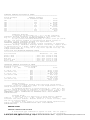
ENGINE IDENTIFICATION CODE TABLE
Application
Esteem
VIN
.................................................
$%
./#.
0
&
# / /0
/&12 $
0$
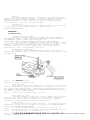
1) Disconnect negative battery cable. Remove rocker cover.
Remove right side inner fender apron extension to make timing marks
visible. Align crankshaft pulley timing mark with TDC mark on timing
belt cover.
2) Remove distributor cap. Ensure rotor is pointing upward
toward distributor hold-down bolt and to No. 1 terminal of distributor
cap. If not correctly oriented, rotate crankshaft 360 degrees.
3) Measure clearance between adjustment screw and valve stem
using thickness gauge. Check intake valve clearance of cylinders No. 1
and 2 and exhaust valve clearance of cylinders No. 1 and 3. Turn
crankshaft one complete revolution (360 degrees). Check intake valve
clearance of cylinders No. 3 and 4 and exhaust valve clearance of
cylinders No. 2 and 4.
4) Ensure clearance is within specification. See
VALVE CLEARANCE SPECIFICATIONS table. If clearance adjustment is
necessary, loosen lock nut and turn adjusting screw. Hold adjusting
screw while tightening lock nut to 106 INCH lbs. (12 N.m). Recheck
clearance.
VALVE CLEARANCE SPECIFICATIONS TABLE
Application
In. (mm)
Engine Cold
Intake & Exhaust
Engine Hot
Intake & Exhaust
&#
NOTE:
...................
.005-.007 (.13-.18)
...................
.007-.008 (.18-.20)
'
#
For reassembly reference, label all electrical connectors,
vacuum hoses and fuel lines before removal. Also, place
mating marks on engine hood and other major assemblies
before removal.
WARNING: ALWAYS relieve fuel pressure before disconnecting any fuel
injection-related component. DO NOT allow fuel to contact
engine or electrical components.
2 #-
2
# /
1) Place transmission in Neutral (M/T) or Park (A/T). Set
parking brake and block drive wheels.
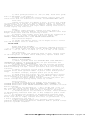
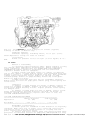
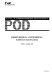
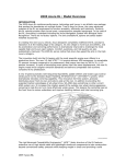
2) Disconnect fuel pump relay connector. Fuel pump relay is
located in relay box, near battery. See Fig. 1.
3) Remove fuel filler cap to release pressure. Reinstall fuel
filler cap. Start engine, and idle until engine dies. Crank engine 2
or 3 times to ensure lines are empty. Reconnect fuel pump
relayconnector.
Fig. 1: Locating Fuel Pump Relay
Courtesy of Suzuki of America Corp.
03 0
CAUTION: When raising or supporting engine or automatic transmission
for any reason, DO NOT use a jack under oil pan. Damage to
oil pump and pick-up strainer could result.
NOTE:
Remove engine and transmission as an assembly. Engine and
transmission assembly must be lowered from vehicle.
Removal
1) Release fuel pressure. See FUEL PRESSURE RELEASE.
Disconnect battery cables. Mark and remove hood. Drain coolant and
remove radiator hoses.
2) Disconnect cooling fan wires. Remove air cleaner assembly.
Remove radiator and cooling fan as an assembly. Disconnect fuel lines
and heater hoses. Identify, mark and remove vacuum lines and hoses at
engine.
3) Disconnect accelerator cable at throttle body. On M/T
models, disconnect clutch cable at transmission. On A/T models,
disconnect gear select cable from transmission. On all models, label
and disconnect all engine and transmission wiring.
4) Raise vehicle. Remove right and left engine undercovers.
Disconnect exhaust pipe at manifold. Loosen A/C compressor pivot bolt.
Remove A/C drive belt and compressor mounting bracket (if equipped).
5) On A/T models, disconnect gearshift control shaft and
gearshift extension rod at transaxle. On all models, drain
transmission and engine oil. Disconnect ball joints, and remove drive
axles. See AXLE SHAFTS - FWD article in DRIVE AXLES section.
6) Attach hoist to engine. Disconnect crossmember from frame
rails. Disconnect left and right side engine mounts. Lower engine and
transmission as an assembly.
Installation
Raise engine/transmission unit into vehicle. Install
engine/transmission mountings to brackets. Install bolts into frame
brackets. Tighten bolts to specification. See TORQUE SPECIFICATIONS.
To complete installation, reverse removal procedure.
0$/4
/0 5#&
Removal
1) Release fuel pressure. See FUEL PRESSURE RELEASE.
Disconnect negative battery cable. Drain cooling system. Remove air
intake hoses and air breather hoses.
WARNING: To avoid severe burns, DO NOT remove radiator drain plug or
cap while engine and radiator are still hot.
2) Remove air cleaner assembly. Label and disconnect all
electrical connections from intake manifold, injectors and throttle
body. Label and disconnect vacuum hoses from intake manifold.
3) Disconnect coolant hoses from manifold and throttle body
and remove upper radiator hose. Remove fuel supply and return lines
from delivery pipe. Disconnect all control cables.
4) Remove intake manifold-to-cylinder head bolts. Remove
intake manifold and throttle body and gasket. Remove remaining
components from intake manifold as required.
(
Installation
To install, reverse removal procedure. Use NEW gaskets.
Tighten bolts to specification. See TORQUE SPECIFICATIONS. Adjust all
control cables and fill cooling system.
6/2 $
/0 5#&
Removal
1) Disconnect negative battery cable. Remove air cleaner
assembly (if necessary). Disconnect oxygen sensor wire connector.
2) Disconnect exhaust pipe from exhaust manifold. Remove
exhaust manifold cover. Remove exhaust manifold stiffener. Remove
exhaust manifold-to-cylinder head bolts. Remove exhaust manifold and
gasket.
Installation
To install, reverse removal procedure. Use NEW exhaust
manifold gasket. Tighten bolts to specification. See
TORQUE SPECIFICATIONS.
7# 0&
6 /&
Removal
1) Release fuel pressure. See FUEL PRESSURE RELEASE.
Disconnect negative battery cable. Drain cooling system and remove
necessary coolant hoses from cylinder head. Remove intake manifold
brace. Label and remove hoses, lines and electrical connectors from
cylinder head, intake manifold and exhaust manifold. Disconnect
exhaust pipe from exhaust manifold and remove brace.
2) Removing exhaust and intake manifolds is not necessary.
Remove rocker arm cover. Fully loosen all rocker arm adjustment
screws. Remove timing belt. See TIMING BELT. Remove air conditioner
compressor and/or generator adjusting arm from cylinder head (if
equipped).
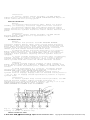
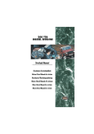
3) Loosen cylinder head bolts in reverse order of tightening
sequence. See Fig. 2. Loosen head bolts in 2 or 3 steps to prevent
cylinder head warpage. Remove head bolts. Using a lifting device,
remove cylinder head with intake and exhaust manifolds attached.
Inspection
1) Check cylinder head for evidence of water leakage or
damage. Remove carbon from combustion chambers. Check cylinder head
for cracks in intake and exhaust ports, combustion chambers and head
surface.
2) Check head warpage at 6 locations. If warpage exceeds
specification, cylinder head should be machined or replaced. See
CYLINDER HEAD table under ENGINE SPECIFICATIONS.
3) Check intake and exhaust manifold seating faces on
cylinder head for warpage. Warpage limit for manifold seating faces is
.004" (.10 mm). If warpage exceeds specification, machine or replace
cylinder head.
Installation
To install cylinder head, reverse removal procedure. Use NEW
head and manifold gaskets. Tighten cylinder head bolts to
specification in 3 steps using proper sequence. See Fig. 2 or 8. See
TORQUE SPECIFICATIONS. Adjust valve clearance. See
VALVE CLEARANCE ADJUSTMENT under ADJUSTMENTS.
Fig. 2: Cylinder Head Bolt Tightening Sequence
Courtesy of Suzuki of America Corp.
50$ 5.
5#
/#
() ,+
!
" ##
Removal
1) Remove water pump, crankshaft pulley and generator. Remove
timing belt cover and timing belt. See TIMING BELT.
2) Drain engine oil. Remove oil dipstick and oil pan. Remove
oil pump pick-up screen. Remove oil pump assembly. Remove oil pump
rotor plate.
3) Using felt pen, mark outer gear for reassembly reference.
Remove inner and outer oil pump gears. Remove plug, relief spring and
relief valve. Drive out oil seal.
Installation
1) Drive in NEW oil seal. Ensure gears are assembled in same
direction as originally installed. Apply thin coat of engine oil to
lip portion of oil seal and inside surfaces of oil pump case and
plate. Install inner and outer rotors.
2) Install rotor plate. Tighten 5 screws. Install 2 oil pump
pins, NEW dipstick "O" ring, NEW seal for oil pick-up tube and NEW oil
pump gasket. Use Oil Seal Guide (09926-18210) to prevent damage to oil
seal during installation of oil pump. See Fig. 3.
3) Apply engine oil to guide and install oil pump. Install
dipstick guide with NEW seal. Install oil pan using silicone-type
sealant. To complete installation, reverse removal procedure. Tighten
bolts to specification. See TORQUE SPECIFICATIONS.
Fig. 3: Installing Oil Seal Guide
Courtesy of Suzuki of America Corp.
$
03 8 #$
Removal
1) Disconnect negative battery cable.
2) Raise vehicle and remove fender apron extension by pushing
center pin into clip. DO NOT push in too far as pin may fall into
fender. Loosen generator, and remove water pump pulley and belt.
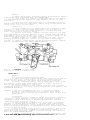
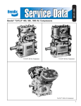
3) Remove crankshaft pulley. Remove timing belt cover. Align
all sprocket timing marks with timing marks on engine. See Fig. 4.
Move up and secure timing belt tensioner.
4) If timing belt is to be reused, mark belt with an arrow
indicating direction of rotation. Remove timing belt from camshaft and
crankshaft sprockets.
CAUTION: DO NOT turn crankshaft more than 90 degrees in either
direction from aligned position. Doing so could damage
piston(s) and/or valve(s) by interference. Also, DO NOT bend
timing belt.
Installation
1) Loosen all valve adjusting screws fully before installing
timing belt. Allow camshaft to rotate freely during belt tension
adjustment. Align timing mark on camshaft sprocket with "V" mark on
timing belt inner cover. See Fig. 4.
2) Turn crankshaft clockwise until punch mark on crankshaft
sprocket is aligned with arrow mark on oil pump. With timing marks
aligned, install timing belt. Ensure direction arrow mark on timing
belt is pointed in direction of crankshaft rotation. Ensure drive side
of belt is free of slack.
3) Move tensioner plate up with finger pressure, and loosely
secure tensioner bolt. Turn crankshaft 2 revolutions clockwise to
remove all slack from belt. Tighten tensioner nut and then tensioner
bolt. See TORQUE SPECIFICATIONS.
4) Ensure timing marks are aligned. Install timing belt outer
() + See TORQUE SPECIFICATIONS. Reverse
cover and tighten to specification.
!
" ##
removal procedure to complete installation. Adjust valve clearance.
See VALVE CLEARANCE ADJUSTMENT under ADJUSTMENTS.
Fig. 4: Aligning Timing Belt & Tensioner (Typical SOHC)
Courtesy of Suzuki of America Corp.
5 4
/
9 ./#. #/ 6 /&12 $
Removal
1) Disconnect negative battery cable. Remove front grille.
Remove hood lock and hood lock support member and disconnect lead wire
from horn. Push center pin of clips to release grille clips.
2) Drain cooling system. Remove radiator, cooling fan and
shroud. Remove A/C condenser and compressor (if equipped), leaving
hoses connected. Remove air cleaner assembly and rocker arm cover.
3) Remove water pump belt and pulley. Remove timing belt. See
TIMING BELT. Use Camshaft Pulley Holder (09917-68220) to secure
camshaft pulley. Remove camshaft sprocket bolt and sprocket.
4) Loosen all valve adjustment lock nuts and valve adjusting
screws to allow rocker arms to move freely.
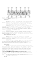
5) Loosen camshaft bearing caps in reverse order of
tightening sequence. See Fig. 5. Loosen bolts in 2 or 3 steps. Remove
camshaft bearing caps and camshaft. Remove rocker arm shaft plug and
timing belt inside cover.
6) Remove intake rocker arms, with clip, from rocker arm
shaft. Remove rocker arm shaft bolts. Push rocker arm shaft slightly
to rear and remove "O" ring from shaft. Remove exhaust rocker arms and
springs while pushing rocker arm shaft toward front of engine.
Installation
1) To install, reverse removal procedure. Install NEW "O"
ring on rear of rocker arm shaft. Ensure flat surface of rocker arm
shaft is facing down and is parallel with cylinder head gasket mating
surface. Tighten camshaft bearing caps in 3 or 4 steps in sequence,
finishing with final torque specification. See Fig. 5. See
TORQUE SPECIFICATIONS.
2) Intake rocker shaft has a .55" (14 mm) stepped end.
Exhaust rocker shaft has a .59" (15 mm) stepped end. Ensure intake
rocker shaft stepped end faces front of engine and exhaust rocker
shaft stepped end faces rear of engine. Adjust valve clearance. See
VALVE CLEARANCE ADJUSTMENT under ADJUSTMENTS.
Fig. 5: Camshaft Bearing Cap Bolt Tightening Sequence
Courtesy of Suzuki of America Corp.
/
6/ $
Removal
For camshaft removal, see ROCKER ARM & VALVE LASH ADJUSTER.
CAUTION: Hydraulic valve lash adjusters cannot be disassembled or
repaired. DO NOT apply force to adjuster body. If removed,
keep immersed in container of clean engine oil.
Inspection
1) Check cam lobes and journals for wear and damage. Use
Plastigage to check bearing clearance. If wear exceeds specification,
repair or replace as necessary. See CAMSHAFT table under ENGINE
SPECIFICATIONS.
2) Use dial indicator and "V" blocks to measure camshaft
runout at center of shaft. If wear exceeds specification, repair or
replace as necessary. See CAMSHAFT table.
Installation
Lubricate camshaft lobes and camshaft bearing journals.
Install camshaft and NEW oil seal in cylinder head. Install camshaft
sprocket. Ensure camshaft sprocket timing marks align with timing
marks on cylinder head. See Fig. 4. To complete installation, reverse
removal procedure.
/
/04 6/ $ 5 #
/#
Removal
Remove engine or engine and transmission. See ENGINE.
Separate transmission from engine. Remove flywheel. Remove oil seal
housing. Remove seal. Inspect oil seal housing for wear or damage.
Repair or replace as necessary.
Installation
Install oil seal in housing. Apply oil to seal lip. Install
oil seal housing with NEW gasket. Tighten housing bolts to
specification. See TORQUE SPECIFICATIONS table. Oil seal housing
gasket will bulge after mounting bolts have been tightened. Trim
excess gasket material even with oil pan gasket surface.
:/$
-2 -
Removal
1) Drain cooling system. Disconnect negative battery cable.
Remove drive belts. Remove A/C compressor (if equipped), leaving hoses
connected.
2) Remove pump pulley. Ensure No. 1 piston is at TDC of
compression stroke. Remove crankshaft pulley bolts and crankshaft
pulley. Remove timing belt cover, tensioner and timing belt. See
TIMING BELT. Remove dipstick and tube. Remove generator mounting
bracket. Remove water pump.
() +
Installation
To install, reverse removal procedure. Ensure all mating
surfaces are clean. Use NEW water pump gasket and NEW dipstick tube
"O" ring.
NOTE:
For further information on cooling systems, see
COOLING SYSTEM SPECIFICATIONS & ENGINE COOLING FANS article
in ENGINE COOLING section.
5 # -/0
!
" ##
Removal
Raise and support vehicle. Drain engine oil. Remove engine
undercovers. Remove exhaust pipe No. 1. Remove transmission stiffener.
Support engine/transmission assembly. Remove crossmember. Remove
crankshaft position sensor from oil pan. Remove oil pan nuts and
bolts. Remove oil pan then oil pump strainer.
Installation
To install, reverse removal procedure. Install oil pan using
silicone-type sealant. Tighten bolts to specification. See
TORQUE SPECIFICATIONS.
#
! %
7# 0&
6 /&
Cylinder Head Disassembly
1) Remove cylinder head. See CYLINDER HEAD under REMOVAL &
INSTALLATION. Remove intake and exhaust manifolds. Remove camshaft.
See CAMSHAFT. Remove rocker arms and shaft. See
ROCKER ARM & VALVE LASH ADJUSTER under REMOVAL & INSTALLATION.
2) Use Valve Spring Compressor (09916-14510) and Valve Lifter
Attachment (09916-14910) to compress valve spring. Use Forceps (0991684510) to remove retainer locks. See Fig. 6. Remove retainers,
springs, valve stem oil seals, spring seats and valves. Keep all
components in order for reassembly reference.
Cylinder Head Reassembly
To assemble, reverse disassembly procedure. Ensure valve
springs are installed with close coiled (small pitch) end down, toward
cylinder head.
Fig. 6: Removing Valve Lock
Courtesy of Suzuki of America Corp.
Valve Springs
Check valve springs for damage. Use a square and flat surface
plate to check spring squareness. Maximum out-of-square is .079" (2.00
mm). Using valve spring tester, check valve spring preload pressure.
See VALVES & VALVE SPRINGS table under ENGINE SPECIFICATIONS. Replace
any weak or out of square springs.
NOTE:
DO NOT reuse old valve stem oil seals
Valve Stem Oil Seals
Place NEW lubricated stem seal on valve guide. Use Valve Stem
Seal Installer (09916-58210). Press seal on valve guide using hand
pressure only. When installer bottoms on head, seal is properly
positioned. Avoid twisting seals during installation.
Valve Guides
1) Check valve stem-to-guide clearance. If clearance exceeds
specification, replace with oversize valve guide. See CYLINDER HEAD
table under ENGINE SPECIFICATIONS.
2) Use Valve Guide Remover (09916-44910). Drive out old
guide.
3) Ream guide bore in cylinder head with 11-mm Reamer (0991638210). Heat cylinder head to 176-212 F (80-100 C).
4) Using Valve Guide Installer Attachment (09916-58210 for
SOHC), drive in new oversized valve guide
valve guide installer
() until
.+
contacts cylinder head.
!
5) Valve guide protrusion is .45" (11.5mm). Ream valve guide
with 5.5-mm Reamer (09916-34550).
6) Clean valve guide bore after reaming. Install valve and
ensure valve stem oil clearance is correct. See CYLINDER HEAD table.
Valve Seat
Inspect valve seats for damage or wear. If valve seat rework
is necessary, use 2 cutters to obtain required angles. On intake and
exhaust valves, first cut should be 15 degrees. Second cut should be
45 degrees to obtain correct seat angle. After cutting valve seats to
correct angles, lap valve seat.
Valves
1) Remove carbon deposits. Inspect for wear, burns or
distortion at face and stem. Replace as necessary. Measure valve head
margin. Check valve stem end for pitting or wear.
2) Measure valve length. Valve stem end may be resurfaced if
no more than .19" (4.8 mm) is removed from valve length. See
VALVES & VALVE SPRINGS table under ENGINE SPECIFICATIONS.
Seat Correction Angles
On intake and exhaust valves, use 15-degree stone to narrow
seat and 45-degree stone to widen seat.
./#. $ / 0
Rocker Arm Shaft Assembly
Check rocker arm-to-shaft oil clearance. Maximum clearance is
.0035 (.09). Check rocker arm shaft runout. Rocker arm shaft runout
limit is .008" (.20 mm) on 16-valve or .004" (.10 mm) on all others.
Lash Adjusters
If tip of rocker arm adjusting screw is worn, replace screw.
If cam riding face of rocker arm is badly worn, replace rocker arm.
7# 0&
8#5 4 /
8#7
Piston & Rod Assembly
1) Remove cylinder head. See CYLINDER HEAD under REMOVAL &
INSTALLATION. Remove oil dipstick guide, oil pan and screen. See
OIL PAN under REMOVAL & INSTALLATION.
2) Ensure pistons, connecting rods and rod caps are marked
for reassembly reference. Remove carbon from top of cylinder bores.
Remove connecting rod caps. Install protective hose over connecting
rod bolts.
3) Remove connecting rod and piston assembly through top of
cylinder block. Mark cylinder number on piston crown. Remove piston
rings.
4) Remove circlips, and push piston pin out by hand.
5) Check piston pin-to-bore fit. Pin should press in piston
smoothly by hand at room temperature. When assembling, apply engine
oil to outside of pin and to piston pin bore.
6) Position piston upward. Install circlips and piston pin.
Install circlips with opening facing either up or down.
Fitting Pistons
1) Check cylinder bore for damage, wear and taper. See
CYLINDER BLOCK under CYLINDER BLOCK ASSEMBLY under OVERHAUL. See
CYLINDER BLOCK table under ENGINE SPECIFICATIONS to determine if block
must be rebored.
2) Pistons are available in .0098" (.25 mm) and .0197" (.50
mm) oversizes. Check outside diameter of piston. Measure at a point .
63" (16.0 mm) from bottom of skirt and at 90 degrees to pin bore.
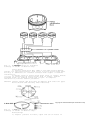
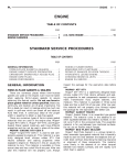
3) Standard pistons are available in 2 sizes. Piston diameter
is determined by numerical mark ("1" or "2") stamped on piston crown.
See Fig. 7.
4) Cylinder bore diameter is determined by numerical mark
("1" or "2") stamped on cylinder block. Numerical marks on cylinder
block, read left to right, indicate bore sizes of cylinders No. 1, 2,
3 and 4, respectively. See Fig. 7.
5) When installing piston into cylinder, ensure piston
numerical mark matches cylinder bore numerical mark to provide correct
piston-to-cylinder clearance.
() /+
Fig. 7: Matching Pistons To Cylinders
Courtesy of Suzuki of America Corp.
Piston Rings
1) Install rings with "R", "RN" or "T" mark facing upward.
Install oil ring spacer first, then rails. Position piston ring gaps.
See Fig. 8. Lubricate all internal surfaces with engine oil before
installation.
2) Ensure arrow on piston head faces front of engine. Ensure
oil hole in connecting rod faces intake side of engine. Install
cylinder head, oil pick-up screen and oil pan. To complete
installation, reverse removal procedure.
CAUTION: Install spacer gap more than 45 degrees from side rail gaps.
Rails should turn smoothly when installed.
() 0+
Fig. 8: Positioning Piston Ring Gaps
Courtesy of Suzuki of America Corp.
Rod Bearings
1) Inspect journals for wear, taper and out-of-round. If
!
" ##
specifications are exceeded, grind journals to undersize or replace
crankshaft. See CRANKSHAFT, MAIN & CONNECTING ROD BEARINGS table under
ENGINE SPECIFICATIONS.
2) Inspect bearing shells for signs of fusion, pitting,
burning or flaking. Observe contact pattern. Standard bearings are
unmarked. Undersized bearings are stamped US025 on back of bearing to
indicate .010" (.25 mm) undersize.
3) Check bearing clearance using Plastigage. See
CRANKSHAFT, MAIN & CONNECTING ROD BEARINGS table. Standard connecting
rod side play is .0039-.0078" (.10-.20mm), with a service limit of .
0138" (.35 mm).
4) To install, reverse removal procedure. Tighten rod nuts to
specification. See TORQUE SPECIFICATIONS.
Crankshaft & Main Bearings
1) Remove engine, or engine and transmission. See ENGINE
under REMOVAL & INSTALLATION. Separate transmission from engine.
Remove timing belt, sprockets, pulley and tensioner. See TIMING BELT
under REMOVAL & INSTALLATION.
2) Remove flywheel and oil pan. Remove rear main oil seal
housing. Remove connecting rod caps. Remove main bearing caps. Remove
crankshaft.
3) Inspect journals for wear, taper and out-of-round
condition. If specifications are exceeded, grind journals to undersize
or replace crankshaft. See CRANKSHAFT, MAIN & CONNECTING ROD BEARINGS
table under ENGINE SPECIFICATIONS.
4) Standard main bearings are color-coded. See Fig. 11. Upper
half of bearing has an oil groove. An arrow mark and number are
embossed on each main bearing cap.
5) Ensure arrow mark on main bearing cap faces toward
crankshaft pulley. Bearing No. 1 is at crankshaft pulley end of
engine. Bearing No. 5 is at flywheel end of engine.
6) Main bearing journal diameter is determined by numerical
mark ("1", "2" or "3") stamped on crankshaft webs of cylinders No. 2
and 3. See Fig. 9.
7) The numerical marks on crankshaft web, read left to right,
indicate journal diameters of bearings No. 1, 2, 3, 4 and 5,
respectively.
8) Determine bearing cap bore diameter with bearing removed.
Bearing cap bore diameter is determined by letter ("A", "B" or "C")
stamped on cylinder block mating surface. See Fig. 10. See appropriate
BEARING CAP BORE DIAMETERS table.
9) The letters stamped on cylinder block mating surface, read
left to right, indicate cap bore diameters of bearing caps No. 1, 2,
3, 4 and 5, respectively. Five standard main bearing sizes are
available. Bearing thickness is determined by color code. See Fig. 11.
See COLOR CODE FOR STANDARD BEARINGS table.
10) Use numerical marks on crankshaft webs and letters
stamped on cylinder block mating surface to determine correct
replacement bearing. See STANDARD BEARING APPLICATION table.
Fig. 9: Locating Numerical Marks On Crankshaft Webs (SOHC)
Courtesy of Suzuki of America Corp.
CRANKSHAFT JOURNAL DIAMETERS TABLE
Numbers Stamped On Webs
"1"
........................
In. (mm)
2.0470-2.0472 (51.994-52.000)
()
"2"
"3"
........................
........................
2.0468-2.0470 (51.988-51.994)
2.0465-2.0468 (51.982-51.988)
Fig. 10: Locating Letters Stamped On Cylinder Block
Courtesy of Suzuki of America Corp.
BEARING CAP BORE DIAMETERS TABLE
Letters Stamped On Block
"A"
"B"
"C"
........................
........................
........................
In. (mm)
2.2047-2.2050 (56.000-56.006)
2.2050-2.2052 (56.006-56.012)
2.2052-2.2054 (56.012-56.018)
Fig. 11: Identifying Main Bearing Color Codes Standard Bearing
Courtesy of Suzuki of America Corp.
Fig. 12: Identifying Main Bearing Color Codes Undersize Bearing
Courtesy of Suzuki of America Corp.
COLOR CODE FOR STANDARD BEARINGS TABLE
Color Painted
Green ..........................
Black ..........................
No Paint .......................
Yellow .........................
Blue ...........................
Thickness - In. (mm)
.0786-.0787
.0787-.0788
.0788-.0789
.0789-.0790
.0790-.0791
(1.996-2.000)
(1.999-2.003)
(2.002-2.006)
(2.005-2.009)
(2.008-2.012)
()
+
STANDARD BEARING APPLICATION TABLE
Letter Stamped
On Block
"A"
"A"
"A"
"B"
"B"
"B"
"C"
"C"
"C"
Numbers Stamped
On Crankshaft Webs
...........................
...........................
...........................
............................
...........................
...........................
............................
...........................
...........................
Color
"1" .............. Green
"2" .............. Black
"3" ........... No Paint
1 ............... Black
"2" ........... No Paint
"3" ............. Yellow
1 ............ No Paint
"2" ............. Yellow
"3" ............... Blue
Undersize Bearings
1) Bearings are available in .010" (.25 mm) undersize.
Undersize bearing thickness is determined by 2 color marks. See
Fig. 11. See COLOR CODE FOR UNDERSIZE BEARINGS table.
2) Use journal finished diameters, 2.0367-2.0373" (51.732-51.
747 mm), and letters stamped on cylinder block mating surface to
determine correct undersize bearing for replacement. See
UNDERSIZE BEARING APPLICATION table.
3) Use Plastigage to ensure correct clearance of installed
undersize bearing. Lubricate bearings before installing. Tighten bolts
to specification in 3 steps. Tighten main bearing caps in following
order: center cap, No. 2 cap, No. 4 cap, front cap and rear cap. See
TORQUE SPECIFICATIONS.
COLOR CODE FOR UNDERSIZE BEARINGS TABLE
Color Painted
Thickness - In. (mm)
Green & Red ....................
Black & Red ....................
Red Only .......................
Yellow & Red ...................
Blue & Red .....................
.0835-.0836
.0836-.0837
.0837-.0838
.0838-.0839
.0839-.0840
(2.121-2.125)
(2.124-2.128)
(2.127-2.131)
(2.130-2.134)
(2.133-2.137)
UNDERSIZE BEARING APPLICATION TABLE
Measured Journal
Diameter - In. (mm)
Letter Stamped
On Block
2.0371-2.0373 ............
(51.744-51.750)
2.0369-2.0371 ............
(51.738-51.744)
2.0367-2.0369 ............
(51.732-51.78)
"A"
"B"
"C"
"A"
"B"
"C"
"A"
"B"
"C"
Color
............. Green & Red
............. Black & Red
................ Red Only
............. Black & Red
................ Red Only
............ Yellow & Red
................ Red Only
............ Yellow & Red
.............. Blue & Red
Thrust Bearing
1) With crankshaft bearing caps installed, check thrust
clearance (end play) using dial gauge to read displacement in axial
thrust direction of crankshaft.
2) Standard thickness of thrust bearing is .0984" (2.50 mm).
Oversize thrust bearings are available in increments of .0049" (.125
mm). If clearance exceeds specification, replace thrust bearing. See
CRANKSHAFT, MAIN & CONNECTING ROD BEARINGS table under ENGINE
SPECIFICATIONS.
Cylinder Block
1) Inspect block for distortion of deck surface. Warpage
limit is .0012-.0024" (.03-.06 mm). Inspect block for cracks,
scratches and other defects. Measure bores at 3 levels for wear, taper
and out-of-round condition.
2) If bore wear, taper or out-of-round exceed specification,
rebore cylinders. See CYLINDER BLOCK table under ENGINE
SPECIFICATIONS.
#
03 0 #28
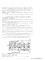
/$ 50 7 $
A force-feed type lubrication system is used. The oil pump is
a trochoid-type pump mounted on the forward portion of the crankshaft.
See Fig. 13.
() *+
!
" ##
Fig. 13: Cross-Sectional View Of Engine Oil Circuit (Typical)
Courtesy of Suzuki of America Corp.
Crankcase Capacity
Crankcase capacity, including filter, is 3.5 qts. (3.3L).
Check dipstick to verify oil level is correct.
RPM.
Oil Pressure
Normal oil pressure is 46.9-61.2 psi (3.3-4.3 kg/cm ) at 4000
5 # -2 Removal & Disassembly
1) Disconnect negative battery cable. Remove radiator cooling
fan, shroud, water pump pulley and drive belt. Remove timing belt
cover, timing belt and tensioner. See TIMING BELT under REMOVAL &
INSTALLATION. Remove generator and bracket and air conditioner
compressor bracket bolts (if equipped).
2) Raise vehicle and drain engine oil. Remove oil dipstick
and oil pan. Remove oil pump pick-up screen. Lock crankshaft with Gear
Stopper (09927-56010) installed at flywheel ring gear. With crankshaft
locked, remove timing belt pulley. Remove oil pan and oil pump
strainer/pickup. Remove oil pump assembly. Remove dip stick guide.
Remove oil pump rotor plate.
3) Mark outer gear with felt pen for reassembly reference.
Remove inner and outer oil pump gears. Remove plug, relief spring and
relief valve.
Inspection
1) Inspect oil pump housing for cracks or damage. Inspect oil
screen for clogging or damage. Inspect oil screen "O" ring. Ensure
relief valve slides smoothly in bore. Inspect pressure relief spring
for damaged coils.
2) Inspect oil pump gears for wear or damage. Using a feeler
gauge, measure radial and side clearance. See Figs. 14 and 22. If
clearance exceeds specification, replace outer rotor or case. See
OIL PUMP SPECIFICATIONS table.
OIL PUMP SPECIFICATIONS TABLE
Radial Clearance
In. (mm)
Application
All Models
..........
.0122 (.310)
Side Clearance
In. (mm)
........
.0059 (.150)
Reassembly & Installation
1) Ensure gears are assembled in same direction as originally
installed. Apply thin coat of engine oil to inner and outer rotors,
lip portion of oil seal and inside surfaces of oil pump case and
plate. Install inner and outer rotors.
2) Install gear plate. Ensure gears turn freely by hand after
gear plate is installed. Install oil pump pins, NEW dipstick "O" ring,
NEW seal for oil pick-up tube and NEW oil pump gasket. Use Oil Seal
()
,+
!
Guide (09926-18210) to prevent damage to oil seal during installation
of oil pump.
3) Apply engine oil to guide, and install pump. Install
dipstick guide with NEW seal. Install oil pan using silicone-type
sealant. Tighten bolts to specification. See TORQUE SPECIFICATIONS.
Fig. 14: Checking Oil Pump Radial Clearance
Courtesy of Suzuki of America Corp.
Fig. 15: Checking Oil Pump Side Clearance
Courtesy of Suzuki of America Corp.
# 1%
"
#
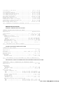
TORQUE SPECIFICATIONS TABLE
Application
Ft. Lbs. (N.m)
Generator Mount & Adjusting Bolts .......... 13-21 (18-28)
Generator Pulley Bolt ........................... 82 (111)
Camshaft Sprocket Bolt ..................... 41-47 (56-64)
Connecting Rod Cap Nut ..................... 24-27 (33-37)
Crankshaft Main Bearing Cap Bolt ........... 37-42 (50-57)
Crankshaft Pulley Bolt ..................... 11-13 (15-18)
Crankshaft Sprocket Bolt
1995-96 ................................ 77-85 (105-115)
1997 ................................... 77-85 (105-115)
Cylinder Head Bolt (1) ..................... 48-52 (65-70)
Drive Plate-To-Torque Converter Bolt ............. 70 (95)
Engine Mounts-To-Block ........................... 33 (45)
Engine Mounts-To-Frame ........................... 37 (50)
Exhaust Manifold Bolt ...................... 13-21 (18-28)
Exhaust Pipe ..................................... 33 (45)
Flywheel Bolt (Drive Plate For A/T) ........ 55-59 (75-80)
Intake Manifold Bolt ....................... 13-21 (18-28)
Fuel Feed Flare Nut .............................. 33 (45)
Oil Pan Drain Plug ......................... 22-30 (30-40)
Oil Filter Mount ........................... 15-18 (20-25)
Spark Plug ................................. 15-22 (20-30)
Timing Belt Tensioner Bolt ................. 18-22 (24-30)
Torque Converter Bolts ........................... 47 (64)
INCH Lbs. (N.m)
Camshaft Bearing Cap Bolt ..................
Cooling Fan Nut ............................
80-106 (9-12)
71-106 (8-12)
()
Distributor Case Bolt ...................... 71-106 (8-12)
Oil Pan Bolt ............................... 80-106 (9-12)
Oil Pressure Switch ...................... 106-133 (12-15)
Oil Pump Mounting Bolt ..................... 80-106 (9-12)
Oil Pump Rotor Plate Screw ................. 80-106 (9-12)
Oil Pump Strainer Bolt ..................... 80-106 (9-12)
Oil Seal Housing Bolt ...................... 80-106 (9-12)
Rear Main Seal Bolt ....................... 89-115 (10-13)
Rocker Arm Shaft Screw ..................... 80-106 (9-12)
Rocker Cover Bolt ............................ 35-44 (4-5)
Timing Belt Outer Cover Bolt ............... 80-106 (9-12)
Timing Belt Tensioner Stud Nut ............. 80-106 (9-12)
Water Pump Mounting Bolt ................... 80-106 (9-12)
Water Pump Pulley Bolt .................... 89-115 (10-13)
(1) - Tighten in sequence. See Fig. 2 or 8.
"
3 0
#
/# 03 0
-
/$ 50
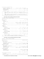
GENERAL ENGINE SPECIFICATIONS TABLE
Application
Specification
Displacement ......................... 97.0 Cu. In. (1.6L)
Bore ..................................... 2.95" (75.0 mm)
Stroke ................................... 3.54" (90.0 mm)
Compression Ratio ................................ 9.5:1
Compression Pressure (1)
Standard .......................... 199 psi (14 kg/cm )
Limit ............................. 156 psi (11 kg/cm )
Maximum Variation ................. 14.2 psi (1 kg/cm )
Fuel System ........................................ SFI
Horsepower HP @ RPM .......................... 98 @ 6000
Torque Ft. Lbs. @ RPM ....................... 96 @ 30 00
(1) - Checked at 250 RPM or higher.
500
$ 03 5&
-
/$ 50
CONNECTING RODS TABLE
Application
In. (mm)
Pin Bore ..................... .7481-.7485 (19.003-19.011)
Maximum Bend ................................. .0020 (.05)
Maximum Twist ................................ .0039 (.10)
Side Play
Standard ......................... .0039-.0078 (.10-.20)
Service Limit .............................. .0138 (.35)
(1) - Information is not available at time of publication.
/04 6/ $"
/ 0 9 500
$ 03 5& 8 / 03
-
/$ 50
CRANKSHAFT, MAIN & CONNECTING ROD BEARINGS TABLE
Application
In. (mm)
Crankshaft
End Play
Standard .......................... .004-.012 (.11-.31)
Service Limit .............................. .015 (.38)
Runout ...................................... .002 (.06)
Main Bearings
Journal Diameter (1)
"1" ..................... 2.0470-2.0472 (51.994-52.000)
"2" ..................... 2.0468-2.0470 (51.988-51.994)
"3" ..................... 2.0465-2.0468 (51.982-51.988)
Journal Out-Of-Round ...................... .0004 (.010)
Journal Taper ............................. .0004 (.010)
Oil Clearance
Standard ...................... .0008-.0016 (.020-.040)
Service Limit ............................ .0024 (.060)
Main Bearing Cap Bore Diameter (2)
"A" ..................... 2.2047-2.2050 (56.000-56.006)
"B" ..................... 2.2050-2.2052 (56.006-56.012)
"C" ..................... 2.2052-2.2054 (56.012-56.018)
()
-+
Connecting Rod Bearings
Journal Diameter ......... 1.7316-1.7323 (43.982-44.000)
Journal Out-Of-Round ...................... .0004 (.010)
Journal Taper ............................. .0004 (.010)
Oil Clearance
Standard ...................... .0008-.0020 (.020-.050)
Service Limit ............................ .0031 (.080)
(1) - Main bearing journal diameter is determined by
numerical mark ("1", "2" or "3") stamped on crankshaft
web.
(2) - Main bearing cap bore diameter is determined by letter
("A", "B" or "C") stamped on cylinder block mating
surface. See Fig. 11.
- $50 " - 0 9
03
-
/$ 50
PISTONS, PINS & RINGS TABLE
Application
In. (mm)
Pistons
Clearance ........................ .0008-.0016 (.02-.04)
Diameter (1)
"1" ..................... 2.9520-2.9524 (74.980-74.990)
"2" ..................... 2.9516-2.9520 (74.970-74.980)
Pins
Diameter ................... .7478-.7480 (18.995-19.000)
Piston Fit ........................................ Slip
Rod Fit ........................................... Slip
Rings
No. 1
End Gap
Standard ...................... .0079-.0138 (.20-.35)
Service Limit ........................... .0276 (.70)
Side Clearance .............. .0012-.0028 (.030-.070)
No. 2
End Gap
Standard ...................... .0079-.0138 (.20-.35)
Service Limit ........................... .0276 (.70)
Side Clearance ................ .0008-.0024 (.02-.06)
No. 3 (Oil)
End Gap
Standard ...................... .0079-.0276 (.20-.70)
Service Limit ........................... .0669 (1.7)
(1) - Piston diameter is determined by numerical mark
("1" or "2") stamped on piston. See Fig. 8.
./#.
9 ./#.
- 03
-
/$ 50
VALVES & VALVE SPRINGS TABLE
Application
Specification
Intake Valves
Seat Angle .........................................
Valve Head Thickness
Standard ........................ .03-.047" (.8-1.2
Service Limit ........................... .024" (.6
Stem Diameter ............ .2152-.2157" (5.465-5.480
Exhaust Valves
Seat Angle .........................................
Valve Head Thickness
Standard ........................ .03-.047" (.8-1.2
Service Limit .......................... .028" (.70
Stem Diameter ............ .2142-.2148" (5.440-5.455
Valve Springs
Free Length
Standard ........................... 1.4500" (36.83
Service Limit ...................... 1.4043" (35.67
Out-Of-Square .......................... .079" (2.00
45
mm)
mm)
mm)
45
mm)
mm)
mm)
mm)
mm)
mm)
Lbs. @ In. (kg @ mm)
Valve Spring Preload
Standard ............ 23.6-27.5 @ 1.24 (10.7-12.5 @ 31.5)
Service Limit ................. 20.5 @ 1.24 (9.3 @ 31.5)
7# 0&
8#5 4 -
/$ 50
()
+
CYLINDER BLOCK TABLE
Application
In. (mm)
Cylinder Bore
Standard Diameter (1)
"1" ..................... 2.9531-2.9535 (75.010-75.020)
"2" ..................... 2.9528-2.9531 (75.000-75.010)
Maximum Taper .............................. .0039 (.10)
Maximum Out-Of-Round ....................... .0039 (.10)
Maximum Deck Warpage ........................ .002 (.05)
(1) - Cylinder bore diameter is determined by numerical mark
("1" or "2") stamped on cylinder block. See Fig. 8.
7# 0&
6 /& -
/$ 50
CYLINDER HEAD TABLE
Application
Specification
Maximum Warpage
Head-To-Block ........................... .002" (.05
Manifold-To-Head ........................ .004" (.10
Valve Seats
Intake & Exhaust Valves
Seat Angle ........................................
Seat Width .................. .0433-.0512" (1.1-1.3
Valve Guides
Valve Stem End Deflection Limit
Intake ................................. .006" (.14
Exhaust ................................ .007" (.18
Intake Valve
Valve Guide I.D. ........ .2165-.2170" (5.500-5.512
Valve Guide Installed Height ........... .45" (11.5
Valve Stem-To-Guide Oil
Clearance ............... .0008-.0020" (.020-.047
Service Limit ....................... .0027" (.07
Exhaust Valve
Valve Guide I.D. ........ .2165-.2170" (5.500-5.512
Valve Guide Installed Height ........... .45" (11.5
Valve Stem-To-Guide Oil
Clearance ............... .0018-.0028" (.045-.072
Service Limit ....................... .0035" (.09
/
6/ $ -
mm)
mm)
45
mm)
mm)
mm)
mm)
mm)
mm)
mm)
mm)
mm)
mm)
mm)
/$ 50
CAMSHAFT TABLE
Application
In. (mm)
Bore Diameter .............. 1.1024-1.1032 (28.000-28.021)
Journal Diameter ........... 1.1000-1.1008 (27.939-27.960)
Journal Runout ............................. .0039 (.10)
Lobe Height
Exhaust Standard ........ 1.4313-1.4376 (36.356-36.516)
Exhaust Service Limit ................. 1.4273 (36.256)
Intake Standard ......... 1.4240-1.4303 (36.171-36.331)
Intake Service Limit .................. 1.4201 (36.071)
Oil Clearance
16-Valve Standard ............. .0016-.0032 (.040-.082 )
16-Valve Service Limit ..................... .0047 (.12)
5 4
/
9 5 4
/
6/ $ -
/$ 50
ROCKER ARM & ROCKER ARM SHAFT TABLE
Application
In. (mm)
Rocker Arm Inside Diameter ... .6293-.6301 (15.985-16.005)
Rocker Arm Shaft Outside
Diameter ................... .6287-.6293 (15.969-15.984)
Rocker Arm-To-Shaft Oil Clearance
Standard ....................... .0005-.0018 (.012-.045)
Service Limit .............................. .0035 (.09)
Rocker Arm Shaft Runout ....................... .008 (.20)
()
.+
#"
()
/+
!
" ##