1
Installation Quick Reference
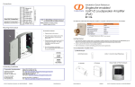
Moving the Clock Connector Cover Plate
Cover plate
Clock Kit Wall Mount Adapter for
Indoor Paging Speakers
1. Unscrew and remove the two attachment
cover screws.
011100*, RAL 9002, Gray White, Standard
011101, RAL 9003, Signal White, Optional
2. Rotate the clock connector cover plate 180
degrees as shown in the picture on the left.
3. Screw and tighten the cover screws to
secure the cover plate in place.
*Replaces the 011023 number.
The Clock Kit Wall Mount Adapter enables the CyberData V2 VoIP Ceiling Speaker to be
upgraded to a highly visible public address device with a time display.
The large display characters are easily read and adjust for ambient light conditions. Time sync
is performed by NTP and a built-in real -time clock.
Power is supplied by the CyberData V2 Speaker from a single PoE connection.
The documentation for this product is released in an English language version only. You can
download PDF copies of CyberData product documentation at:
Connecting Power (optional power injector)
http://www.cyberdata.net/products/voip/digitalanalog/clockkit/docs.html
Wall Mount Adapter Parts
(1) Wall Mount Adapter
To Network
(1) Template for Wall Mount
Adapter and Screw Holes*
(1) Drywall Mounting Kit
(4) Plastic Ribbed Anchors
*Note: the ceiling speaker
wall-mounted adapter screws
will be included in the ceiling
speaker kit.
(4) #6 Sheet Metal Screws
Ethernet
Optional power injector
(CyberData # 010867A)
Device
Install Jumper JP1 Prior to Installing the Clock Kit
Contacting CyberData
Connecting Power (PoE)
Corporate Headquarters
CyberData Corporation
2555 Garden Road
Monterey, CA 93940, USA
To PoE Network
Phone: 831-373-2601
Fax: 831-373-4193
www.CyberData.net
Sales: (831) 373-2601 ext. 334
Support: 831-373-2601 ext. 333
Email: [email protected]
RMA Dept: (831) 373-2601 ext. 136
Email: [email protected]
Warranty information available at:
http://www.CyberData.net/index.html
© 2010, CyberData Corporation, ALL RIGHTS RESERVED
930349B
Quick Reference
Make sure that jumper JP1 is installed prior to installing the Clock Kit (see the picture on the right). Installing JP1 powers
the Real Time Clock from the battery. If you do not install JP1, the clock will lose it's time when the power is disconnected.
Jumper Functions:
Jumper
Function
JP1
Battery - Connect
JP2
Manufacturing - Open
JP3
Manufacturing - Open
JP4
Manufacturing - Open
JP5
Manufacturing - Open
Quick Reference
JP1
930349B
© 2010, CyberData Corporation, ALL RIGHTS RESERVED
Mounting
Features
10.70 [271.8]
Dimensions are in Inches [mm]
Network cable routed through a wall
into the rear of the Clock Kit Wall
Mount Adapter.
CyberData Part #011098 or #011099
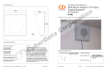
To mount a Clock Kit Wall Mount Adapter:
1. Use the TEMPLATE on this document to drill
four holes in the wall for the anchors and screws.
• Place the four PLASTIC RIBBED ANCHORS
into the holes you prepared.
• Screw the four #6 SHEET METAL SCREWS into
the four PLASTIC RIBBED ANCHORS.
2. Position the CLOCK KIT WALL MOUNT
ADAPTER over the four #6 SHEET METAL
SCREWS.
Step 2
Step 4
4. Connect Cables to the IP SPEAKER ASSEMBLY:
From Network
to Speaker
• Plug the ribbon cable from the clock into the IP
SPEAKER ASSEMBLY.
Step 1
• Plug the Ethernet cable from the network into
the IP SPEAKER ASSEMBLY. The yellow light
verifies the network connection. See the back of
this placemat for details.
Note: You can route the Ethernet cable through
the back or through the slots at the top or bottom
of the WALL MOUNT ADAPTER.
Step 5
Step 3
Step 4
(3) 8-32 x 1 1/4” Mounting
Screws (from the Ceiling
Speaker Drop Ceiling
Mounting Kit)
From Clock
to Speaker
Ambient light detector
Dimensions
11.8 [300]
5.4 [137]
5. Position the IP SPEAKER ASSEMBLY into the
CLOCK KIT WALL MOUNT ADAPTER so
that the IP SPEAKER ASSEMBLY screw holes
align with the mounting holes in the CLOCK
KIT WALL MOUNT ADAPTER.
• Use three 8-32 x 1 1/4” MOUNTING SCREWS
(from the Ceiling Speaker Drop Ceiling
Mounting Kit) to secure the IP SPEAKER
ASSEMBLY to the WALL MOUNT ADAPTER.
PM LED
10°
13.5 [343]
7.00 [177.8]
3. Move the CLOCK CONNECTOR COVER
PLATE. See the back of this placemat for details.
Dimensions are in Inches [Millimeter]