1
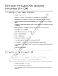
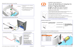
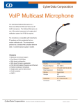
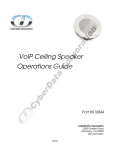
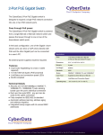
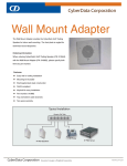
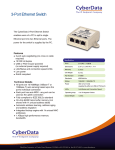
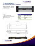
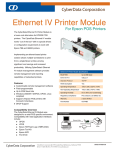
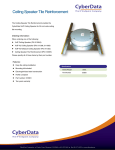
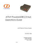
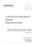
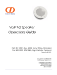
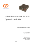
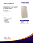
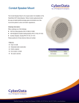
Installation Quick Reference
Overall Dimensions
10.5
[51mm]
Wall Mount Adaptor for Indoor
Paging Speakers
4.9
[124mm]
SiP Compliant
010882
The Wall Mount Adaptor for Indoor Paging Speakers is an adapter that is built for a CyberData Ceiling speaker.
11.4
[290mm]
inches
[ mm ]
Contacting CyberData
Corporate Headquarters
Warranty
CyberData Corporation
2555 Garden Road
Monterey, CA 93940, USA
CyberData warrants its product against defects in material and
workmanship for a period of two years from the date of purchase.
Should the product fail within the warranty period, CyberData will
repair or replace the product free of charge. This warranty includes all
parts and labor. Should the product fail out-of-warranty, a flat rate
repair charge of one half the purchase price will be assessed. Repair
costs for products that are in warranty, but damaged by improper
modifications or abuse, are charged at the out-of-warranty rate.
Products returned to CyberData, both in and out-of-warranty, are
shipped to CyberData at the customer’s expense. Charges for
shipping repaired products to the customer are paid by CyberData.
Phone: 831-373-2601
Fax: 831-373-4193
www.CyberData.net
Sales: (831) 373-2601 ext. 334
Support: 831-373-2601 ext. 333
Email: [email protected]
(1) Wall Mount Adapter
930194A
Quick Reference
(1) Template for Wall Mount
Adapter and Screw Holes*
(1) Drywall Mounting Kit
(4) Plastic Ribbed Anchors
For product service, contact the Returned Materials Authorization
(RMA) department. A product will not be accepted for return without
an approved RMA number. Send the product, in its original package,
to: CyberData Corporation, 2555 Garden Road, Monterey, CA 93940,
Attention: RMA “your RMA number”
RMA Dept: (831) 373-2601 ext. 136
Email: [email protected]
© 2007, CyberData Corporation, ALL RIGHTS RESERVED
Wall Mount Adapter Parts
*Note: the ceiling speaker
wall-mounted adapter screws
will be included in the ceiling
speaker kit.
(4) #8 Sheet Metal Screws
Quick Reference
930194A
© 2007, CyberData Corporation, ALL RIGHTS RESERVED
Connecting Power to the Speaker
PoE
Power Injector (Optional)(CyberData #010867A)
Ethernet
Ethernet
Device
Power injector
Mounting the Speaker
4
1. Use the TEMPLATE on the back of this
document to drill four holes in the wall for the
anchors and screws.
1
3 2
2. Place the four PLASTIC RIBBED ANCHORS in
the holes you prepared.
6
10” [254mm]
To mount a Wall Mount Adapter:
3. Position the WALL MOUNT ADAPTER over
the holes.
5
7
4. Use the four #8 SHEET METAL SCREWS to
secure the WALL MOUNT ADAPTER.
5. Plug the Ethernet cable into the IP SPEAKER
ASSEMBLY. The yellow light verifies the
network connection.
Note: You can route the Ethernet cable through
the back or through the slots at the top or bottom
of the WALL MOUNT ADAPTER.
Network cable routed through
a wall into the rear of the Wall
Mount Adapter.
6. Position the IP SPEAKER ASSEMBLY in the
WALL MOUNT ADAPTER so that the IP
SPEAKER ASSEMBLY screw holes align with
the mounting holes in the WALL MOUNT
ADAPTER.
7. Use three 8-32 x 1 1/4” MOUNTING SCREWS
to secure the IP SPEAKER ASSEMBLY to the
WALL MOUNT ADAPTER.
© 2007, CyberData Corporation, ALL RIGHTS RESERVED
930194A
Quick Reference
7” [178mm]
4 x 0.1875” [4.8mm] Hole for Mounting
Quick Reference
930194A
© 2007, CyberData Corporation, ALL RIGHTS RESERVED