1
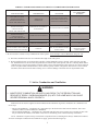
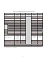
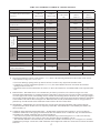
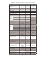
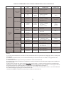
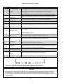
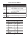
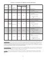
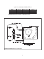
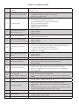
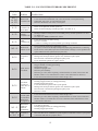
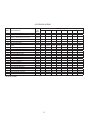
TABLE 11.7: EXAMPLES OF THERMAL PURGE OPERATION
Thermal Purge Settings
Boiler
Temp at
Start Temp Begin
Time (Pt)
(St)
Call
Boiler Behavior
Example
#
Call for
Heat
From
Use of
DHW Zone
1
T-T
N/A
2 min.
140F
130
2
T-T
N/A
2 min.
140F
150
3
DHW
DHW (dh=dh)
2 min.
140F
150
4
Heat T’stat
on DHW Heat (dh=tt2)
terminals
2 min.
140F
150
•
•
•
•
2 minutes have passed
OR
Temperature falls below 140
•
•
DHW Circulator starts immediately
Burner fires immediately
•
“DHW” Circulator starts
immediately
Burner fires when either:
•
•
5
T-T
N/A
2 min.
145F
150
•
•
6
T-T
N/A
3 min.
140
150
Heating Circulator starts
immediately
Burner fires immediately
Heating Circulator starts
immediately
Burner fires when either:
•
2 minutes have passed
OR
Temperature falls below 140
Heating Circulator starts
immediately
Burner fires when either:
2 minutes have passed
OR
Temperature falls below 145
Heating Circulator starts immediately
Burner fires when either:
3 minutes have passed
OR
Temperature falls below 140
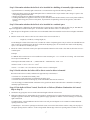
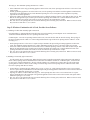
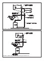
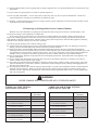
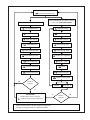
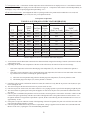
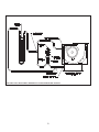
Pt (DHW Priority) - If this feature is turned on, and simultaneous calls for heat and DHW are present, the heating circulator will
be forced off for as long as it takes the boiler to satisfy the call for DHW. This feature is sometimes useful when the boiler size is
marginal for the peak DHW demand, but should be used with caution as it can result in lack of heat if the DHW call is very long,
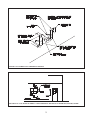
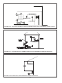
or if there is a problem with the DHW zone which causes the DHW demand to be indefinite. Figure 11.8 describes the behavior of
both the Heating and DHW Circulators with Pt turned both ON and OFF.
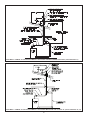
dh (Use of DHW zone) - Although the second zone on the boiler is designated “DHW”, it can be used as a second heating zone by
setting dh = “tt2” instead of dh=”dh”. When the “DHW” zone is used for heating, the thermal purge function is active when this
zone calls for heat. When dh=tt2, the setting of Pt (DHW priority) is ignored.
rst (Reset) - Used to reset the boiler from a hard lockout (as an alternative to momentarily interrupting power to the control).
Pressing the up key will turn rst momentarily to on. When it goes back off (typically within one or two seconds), the control is
reset.
55
55