1
Hardware
Installing the Board
The Ndigo5G board can be installed in any x4 (or higher amount of lanes) PCIe slot. If the slot
electrically supports less than 4 lanes, the board will operate at lower data throughput rates.
Using a single Ndigo5G, no further connections need to be made. For applications that require
more than 4 ADC channels, several Ndigo boards can be operated in sync. Any board of the Ndigo
product line can be synced to other Ndigo boards, allowing, for instance, for a combination of high
speed ADCs (Ndigo5G) and slower high resolution ADCs (Ndigo250M-14) or the upcoming Ndigo
TDC.
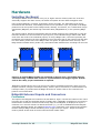
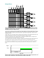
The signals used for board synchronization and inter-board triggering are transferred on a bus between the boards. Join all C2 connectors (see Figure 3) on the boards using a ribbon cable. Both
ends of the bus need to be terminated properly. If using a Ndigo Crate, connectors providing the
termination are located on the crate mainboard next to the PCIe slots to the extreme left and right.
For more details, please refer to the Ndigo Crate user guide. In applications that use only a few
Ndigo boards installed directly inside a PC, termination PCBs available from cronologic can be used.
termination
C2
C2
C2
termination
C1
C1
C1
Figure 1: If several Ndigo boards are connected to work in sync , the boards must be
connected using a ribbon cable as bus for synchronization and trigger signals. At both
ends of the cable, proper termination is required.
Ndigo5G's standard device driver can be used to read out all boards and acquire data. For more
complex scenarios, using the cronoSync-library, which is part of cronoTools, is recommended. The
cronoSync library is provided with the Ndigo device driver. Please refer to the cronoTools user
guide for more information.
Ndigo5G External Inputs and Connectors
Connectors
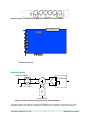
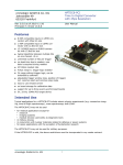
The inputs of the Ndigo5G are located on the PCI bracket. Figure 3 shows the location of the 4 analog inputs A to D and the two digital inputs G (GATE) and T (TRIGGER). Furthermore, two board interconnection connectors can be found at the top edge of the Ndigo5G, as displayed in Figure 3.
Connector C1 is used for a board-to-board connection (e. g. to link a HPTDC8-PCI and a Ndigo5G
via a Ndigo Extension board, see chapter Extension Card). Connector C2 is used as a bus interface
between multiple Ndigo boards distributing clock, trigger and sync signals . Proper termination
must be placed at both ends of the bus interconnection ribbon cable.
cronologic GmbH & Co. KG
3
Ndigo5G User Guide