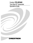
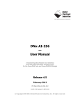
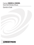
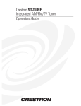
1
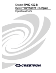
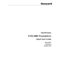
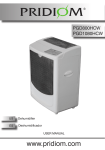
CRESTRON
Contents
Two-Way RF Transceiver
1
Description................................................................................................................................. 1
Functional Description ................................................................................................ 1
Physical Description.................................................................................................... 1
Leading Specifications............................................................................................................... 4
Setup .......................................................................................................................................... 5
Identity Codes ............................................................................................................. 5
Preparation for Use...................................................................................................... 8
Programming ............................................................................................................... 9
Problem Solving ...................................................................................................................... 12
Troubleshooting ........................................................................................................ 12
Further Inquiries........................................................................................................ 13
Syntax........................................................................................................................ 13
Return and Warranty Policies.................................................................................................. 15
Merchandise Returns / Repair Service ...................................................................... 15
CRESTRON Limited Warranty ................................................................................ 15
Operations Guide - DOC. 5701
Contents • i
CRESTRON
Two-Way RF Transceiver
Description
Functional Description
The CNRFGWX is a two-way radio frequency (RF) transceiver that communicates
with all of CRESTRON’s Spectrum family of touchpanels in the CRESNET II
remote control system (herein referred to as the CRESNET II system). The unit
receives RF signals from one or more Spectrum touchpanels and translates them into
commands for transmission over the CRESNET II network. Feedback signals are
transmitted from the CNRFGWX to the Spectrum touchpanels for real-time
confirmation of commands. Up to 16 Spectrum touchpanels can communicate with
one CNRFGWX. If more touchpanels are needed, add more CNRFGWXs.
CRESTRON’s exclusive RF engineering permits transmission over extended ranges
and utilizes spread spectrum technology. Signals can travel up to 1000 feet to and
from the CNRFGWX, even through walls. Spread spectrum eliminates the risk of
signal ‘drop-out’ by automatically scanning for the best frequency.
Physical Description
The CNRFGWX, shown after this paragraph, is housed in a black enclosure with
silk-screened labels on the front and rear panels. On the front of the unit there are
five LEDs for indicating the unit’s current status. The front panel also has a
connector for antenna attachment (supplied). All other connections are made on the
back of the unit. There are four rubber feet on the base of the unit for stability and to
prevent slippage.
Operations Guide - DOC. 5701
Two-Way RF Transceiver • 1
CRESTRON
CNRFGWX Physical Views
CNRFGWX Ports
Three network ports are provided on the back of the CNRFGWX. Each has a silkscreened label. Refer to illustration and descriptions below.
CNRFGWX Ports
NOTE: All CRESNET (NET) connectors, modular and four-wire, can be used
simultaneously.
2 • Two-Way RF Transceiver
Operations Guide - DOC. 5701
CRESTRON
NET (Modular CRESNET)
These two 6-pin, 6-position RJ11 modular jacks are used to connect the CNRFGWX
to modular devices in the CRESNET II system. Two NET ports are available so that
network units can be daisy-chained together. Review the latest revision of the
Network Modular Cable Requirements (Doc. 5682).
NOTE: Most 4-conductor phone cables are wired in a crisscross fashion and are not
compatible with CRESTRON equipment.
NET (Four-Wire CRESNET)
This 4-pin connector is used to connect the CNRFGWX to other four-wire devices
in the CRESNET II system. Review the latest revision of the Network Interconnect
Drawing (Doc. 5411).
CNRFGWX Indicators
There are five LED indicators located on the front panel of the CNRFGWX. Refer to
illustration and descriptions below. The front panel also has a connector which
attaches to the supplied antenna and is used to transmit and receive RF signals from
the Spectrum touchpanels.
CNRFGWX Indicators
PWR (Power)
This LED illuminates when 24 volts DC is supplied to the CNRFGWX.
NET
This LED illuminates when communication between the CRESNET II system and
the CNRFGWX is established. Illumination indicates that the SIMPL program
currently loaded has a network device defined at the same NET ID as the
CNRFGWX.
SIG
This LED illuminates when the CNRFGWX radio is operational.
Rx
This LED illuminates when the CNRFGWX receives a command from a remote
Spectrum touchpanel.
Tx
This LED illuminates when the CNRFGWX transmits a command to a remote
Spectrum touchpanel.
Operations Guide - DOC. 5701
Two-Way RF Transceiver • 3
CRESTRON
Leading Specifications
The table below provides a summary of leading specifications for the CNRFGWX.
Dimensions and weight are approximations rounded to the nearest thousandth unit.
Leading Specifications of the CNRFGWX
SPECIFICATION
Power Requirements
CRESNET II Workshop
CRESNET II Operating System
STS VisionTools for Windows
Compiler
Dimensions & Weight
DETAILS
24 VDC, Load Factor of 5 Watts
Version 5.20 or later
3.17.26 or later
Version 10.4 or later
3.17.15 or later
Height: 1.700 in (4.318 cm)
Width: 6.940 in (17.628 cm)
Depth: 6.322 in (16.058 cm)
Weight: 2.100 lb (0.953 kg)
NOTE: Equipment has been tested and found to comply with the limits for a Class
B digital device, pursuant to part 15 of the FCC Rules. These limits are designed to
provide reasonable protection against harmful interference in a residential
installation. The equipment generates, uses and can radiate radio frequency energy
and, if not installed and used in accordance with the instructions, may cause harmful
interference to radio communications. However, there is no guarantee that
interference will not occur in a particular installation. If this equipment does cause
harmful interference to radio or television reception, which can be determined by
turning the equipment off and on, the user is encouraged to try to correct the
interference by one or more of the following measures:
Reorient or relocate the receiving antenna.
Increase the separation between the equipment and receiver.
Connect the equipment into an outlet on a circuit different from that to which
the receiver is connected.
Consult the dealer or an experienced radio/TV technician for help.
As of the date of manufacture, the unit has been tested and found to comply with
specifications for CE marking.
4 • Two-Way RF Transceiver
Operations Guide - DOC. 5701
CRESTRON
Setup
Identity Codes
The CNRFGWX possesses two distinct types of identity codes: NET ID and RF
CHANNEL. These codes are assigned to the unit from CRESTRON software.
NET ID
Every equipment and user interface within the CRESNET II system requires a
unique identity code (NET ID). These codes are recognized by a two-digit
hexadecimal number from 03 to FE. The NET ID of each unit must match an ID
CODE specified in the “NET.ID” statement of the CRESNET II SIMPL-I program
in order for the device to be addressed properly. The NET ID of each CNRFGWX
has been factory set to 24, but may be changed from the PC via STS VisionTools™
for Windows or the CRESNET II Workshop.
Change NET ID via STS/VTW
Attach the CNRFGWX to CRESNET II system (verify that the software is running)
and complete the following steps to change the NET ID.
1.
Select ViewPort from the Tools pull-down menu to open the “Crestron
Performance Viewport” dialog box.
2.
Select Set Network ID from the Options pull-down menu. The software
checks the baud rate and then opens the “Set Network ID” dialog box.
3.
Notice the list of current network devices in the dialog box. Highlight
the CNRFGWX.
4.
The NET ID of the CNRFGWX (24) appears in the box below the list.
Use the scroll arrow to assign another NET ID.
5.
When the newly assigned NET ID appears, select the Set ID button to
initiate the change.
6.
The software responds with a successful message to confirm the new
NET ID.
7.
To verify this procedure, select Report Network Device from the
Options pull-down menu. Confirm that the CNRFGWX has a new
NET ID code.
Change NET ID via CRESNET II Workshop (v5.20 or later)
Attach the CNRFGWX to CRESNET II system (verify that the workshop is open
and running) and complete the following steps to change the NET ID.
Operations Guide - DOC. 5701
1.
Highlight performance Viewport from the UTILITIES MENU of the
CRESNET II Workshop.
2.
Depress the key combination ALT-I. The Workshop responds with the
screen shown after this paragraph and requests the old NET ID code
for the CNRFGWX.
Two-Way RF Transceiver • 5
CRESTRON
Changing the NET ID - CNRFGWX Workshop Screens (1 of 3)
3.
Enter the old NET ID code (in two-digit hexadecimal format) and
depress ENTER. The Workshop responds with the screen shown below
and requests a new NET ID code for the CNRFGWX.
Changing the NET ID - CNRFGWX Workshop Screens (2 of 3)
4.
Enter a new NET ID code (in two-digit hexadecimal format) and
depress ENTER. The Workshop responds with the screen shown below
that displays a message stating the “New ID” command has been sent.
Changing the NET ID - CNRFGWX Workshop Screens (3 of 3)
6 • Two-Way RF Transceiver
Operations Guide - DOC. 5701
CRESTRON
5.
To verify this procedure, depress F4 to perform a network poll.
Confirm that the CNRFGWX has a new NET ID code.
RF CHANNEL
For a CNRFGWX transceiver to communicate to wireless Spectrum touchpanels a
unique communication identity code (RF CHANNEL) is required. This code is
necessary to secure RF communications between a single CNRFGWX and up to 16
individual Spectrum touchpanels. There are 16 possible codes for the CNRFGWX
ranging from 0 to F (hexadecimal number).
The CNRFGWX RF CHANNEL is factory set to “0”. The code can be changed via
the CRESNET II Workshop while the CNRFGWX is connected to the network.
Complete the following steps to change the RF CHANNEL.
1.
Highlight performance Viewport from the UTILITIES MENU of the
CRESNET II Workshop.
2.
Depress the key combination ALT-Q. The Workshop responds with the
screen shown below and requests the NET ID code for the given
CNRFGWX.
Changing the RF CHANNEL - CNRFGWX Workshop Screens (1 of 3)
3.
Enter the NET ID code (in two-digit hexadecimal format) and depress
ENTER. The Workshop responds with the screen shown below and
requests a new RF CHANNEL code for the CNRFGWX.
Changing the RF CHANNEL - CNRFGWX Workshop Screens (2 of 3)
Operations Guide - DOC. 5701
Two-Way RF Transceiver • 7
CRESTRON
4.
Enter a new RF CHANNEL code (in hexadecimal) and depress
ENTER. Use two significant digits. Therefore, the first digit is always
“0”. The Workshop responds with the screen shown below that
displays a message stating the “New CNRFGWX Channel Number”
command has been sent.
Changing the RF CHANNEL - CNRFGWX Workshop Screens (3 of 3)
5.
To verify this procedure, depress F4 to perform a network poll.
Confirm that the CNRFGWX has a new RF CHANNEL code.
Preparation for Use
Refer to the hookup diagram below which illustrates the CNRFGWX connections to
the CRESNET II system. Other than making the power connection last, complete the
connections in any order.
NOTE: Refer to the latest revision of the CRESTRON Network Modular Cable
Requirements (Doc. 5682) or the Network Interconnect Drawing (Doc. 5411) when
making connections to the ports labeled NET.
CRESNET II System Hookup Connections for CNRFGWX
CRESNET II SYSTEM
(CNRACK OR CNRACK-D
OR CNMS)
EXPAND BY DAISY CHAINING
TO MODULAR UNITS OR USE
CN-RJ11 AND CONNECT TO
FOUR-WIRE NETWORK DEVICES
8 • Two-Way RF Transceiver
Operations Guide - DOC. 5701
CRESTRON
Programming
SIMPL
SIMPL is CRESTRON’s programming language designated for easy implementation
of the control system requirements. The objects that are used in SIMPL are called
symbols.
The block diagram shown below exemplifies use of the CNRFGWX in a simple
volume control application where UP and DOWN ramp a bargraph to an ST-VC,
volume/tone control module, with a time interval of five seconds. It also shows
digital, analog, and indirect text feedback to the panel. When UP or DOWN is
pressed, the buttons highlight for as long as they are pressed. The bargraph moves up
or down when the UP or DOWN buttons are pressed. When MUTE is pressed,
Channel A of the ST-VC is muted and the text "MUTED" is sent to the touchpanel.
When the ST-VC is unmuted, a "-" is sent to the touchpanel.
CNRFGWX SIMPL Program
Workshop
The CRESNET II Workshop is designed to simplify the various operations needed
to program and run a CRESNET II control system. The series of screen displays
shown after this paragraph are accessible from the “Define Network” option of the
SIMPL-I Menu in the CRESNET II Workshop. These screens are shown to clarify
the means of assigning signal names for the SIMPL program in the previous
illustration.
Operations Guide - DOC. 5701
Two-Way RF Transceiver • 9
CRESTRON
CNRFGWX Workshop Screens (1 of 5)
CNRFGWX Workshop Screens (2 of 5)
CNRFGWX Workshop Screens (3 of 5)
10 • Two-Way RF Transceiver
Operations Guide - DOC. 5701
CRESTRON
CNRFGWX Workshop Screens (4 of 5)
CNRFGWX Workshop Screens (5 of 5)
Operations Guide - DOC. 5701
Two-Way RF Transceiver • 11
CRESTRON
Problem Solving
Troubleshooting
The table below provides corrective action for possible trouble situations. If further
assistance is required, please contact a CRESTRON technical support representative.
CNRFGWX Troubleshooting
TROUBLE
POSSIBLE CAUSE(S)
PWR LED does
not illuminate.
NET LED does
not illuminate.
CNRFGWX is not
receiving network power.
CNRFGWX NET ID is
not set to match the NET
ID of the SIMPL
program.
NET ID setting changes
after CNRFGWX is
powered up.
NET LED is on, Unit is not
but unit does
communicating on
not
network.
provide control. CNRFGWX RF ID is not
set to match the RF ID of
the SIMPL program.
CNRFGWX NET ID is
not unique, two or more
units share the same
NET ID.
Rx LED does
Spectrum touchpanel is
not illuminate
out of range.
when operating CNRFGWX and
Spectrum
Spectrum touchpanels
touchpanel.
are not on same RF
CHANNEL.
Tx LED
Spectrum touchpanel is
illuminates
out of range.
when active, but CNRFGWX and
Spectrum
Spectrum touchpanels
touchpanel does are not on same RF
not respond.
CHANNEL.
Spectrum touchpanel is
set to wrong RF ID.
12 • Two-Way RF Transceiver
CORRECTIVE ACTION
Confirm that power is supplied to the
network.
Enter Viewport via VTW and poll the
network. Verify that the NET ID for the
CNRFGWX is properly set to match the
SIMPL program. Note that NET ID and
RF ID are separate parameters.
Power down CNRFGWX. Power up to
reset NET ID.
Check network cabling for solid
connections and correct pinouts.
Enter Viewport via VTW and poll the
network. Verify that the RF ID for the
CNRFGWX is properly set to match the
SIMPL program. Note that NET ID and
RF ID are separate parameters.
Verify that each NET ID is used once.
Move Spectrum touchpanel closer.
Verify that the CNRFGWX and Spectrum
touchpanels are on the same RF
CHANNEL. Refer to "Identity Codes"
paragraph in this guide.
Move Spectrum touchpanel closer.
Verify that the CNRFGWX and Spectrum
touchpanels are on the same RF
CHANNEL. Refer to "Identity Codes"
paragraph in this guide.
Verify that Spectrum touchpanel RF ID is
properly set to match the RF ID set in the
CRESNET II Workshop. Refer to the
"Identity Codes" paragraph in the latest
revision of the OperationsGuide for the
Spectrum touchpanels.
Operations Guide - DOC. 5701
CRESTRON
CNRFGWX Troubleshooting (Continued)
TROUBLE
POSSIBLE CAUSE(S)
CORRECTIVE ACTION
CNRFGWX
Network wiring is
does not
incorrect.
report NET ID
Unit is damaged.
when polling the
network through
Viewport. Other
devices are
reported.
Check network cabling for solid
connections and correct pinouts.
Contact CRESTRON technical support
representative.
Intermittent
response from
CNRFGWX
during
transmission.
Refer to corrective action when LEDs do
not illuminate.
Verify that large amount of metal is not in
vicinity of transmission.
Refer to causes when
LEDs do not illuminate.
CNRFGWX is in vicinity
of metal.
Further Inquiries
If after reviewing this Operations Guide for the CNRFGWX, you can not locate
specific information, please take advantage of CRESTRON's award winning
technical support team in your area. Dial one of the following numbers.
•
In the US and Canada, call Crestron’s corporate headquarters at
1-888-CRESTRON [1-888-273-7876] or 1-201-767-3400.
•
In Europe, call Crestron International at +32-15-50-99-50.
•
In Asia, call Crestron Asia at +852-2341-2016.
•
In Latin America, call Crestron Latin America at +5255-5093-2160.
•
In Australia, call Crestron Pacific at +613-9480-2999.
For local support from exclusive Crestron factory-trained personnel in New Zealand
call Amber Technologies at +649-410-8382.
Syntax
The following syntax codes for the CNRFGWX are provided for compatibility
purposes only.
Operations Guide - DOC. 5701
NET.ID<03 to FE>:CNRFGWX
\CNRFGWX Definition
TRANSMITTER <00 to 0F>:STTW
i1 = <signal name>
“
i999 = <signal name>
o1 = <signal name>
“
o999 = <signal name>
AI1 = <signal name>
“
AI256 = <signal name>
\STX Definition
\First button on touchpanel
\Last button on touchpanel
\First feedback to touchpanel
\Last feedback to touchpanel
\First analog from touchpanl
\Last analog from touchpanl
Two-Way RF Transceiver • 13
CRESTRON
AN1 = <signal name>
“
AN256 = <signal name>
14 • Two-Way RF Transceiver
\First analog feedback to touchpanl
\Last analog feedback to touchpanl
Operations Guide - DOC. 5701
CRESTRON
Return and Warranty Policies
Merchandise Returns / Repair Service
1.
No merchandise may be returned for credit, exchange, or service without prior authorization
from CRESTRON. To obtain warranty service for CRESTRON products, contact the factory
and request an RMA (Return Merchandise Authorization) number. Enclose a note specifying
the nature of the problem, name and phone number of contact person, RMA number, and
return address.
2.
Products may be returned for credit, exchange, or service with a CRESTRON Return
Merchandise Authorization (RMA) number. Authorized returns must be shipped freight
prepaid to CRESTRON, Cresskill, N.J., or its authorized subsidiaries, with RMA number
clearly marked on the outside of all cartons. Shipments arriving freight collect or without an
RMA number shall be subject to refusal. CRESTRON reserves the right in its sole and
absolute discretion to charge a 15% restocking fee, plus shipping costs, on any products
returned with an RMA.
3.
Return freight charges following repair of items under warranty shall be paid by
CRESTRON, shipping by standard ground carrier. In the event repairs are found to be nonwarranty, return freight costs shall be paid by the purchaser.
CRESTRON Limited Warranty
CRESTRON ELECTRONICS, Inc. warrants its products to be free from manufacturing defects in
materials and workmanship under normal use for a period of three (3) years from the date of
purchase from CRESTRON, with the following exceptions: disk drives and any other moving or
rotating mechanical parts, pan/tilt heads and power supplies are covered for a period of one (1)
year; touchscreen display and overlay components are covered for 90 days; batteries and
incandescent lamps are not covered.
This warranty extends to products purchased directly from CRESTRON or an authorized
CRESTRON dealer. Purchasers should inquire of the dealer regarding the nature and extent of the
dealer's warranty, if any.
CRESTRON shall not be liable to honor the terms of this warranty if the product has been used in
any application other than that for which it was intended, or if it has been subjected to misuse,
accidental damage, modification, or improper installation procedures. Furthermore, this warranty
does not cover any product that has had the serial number altered, defaced, or removed.
This warranty shall be the sole and exclusive remedy to the original purchaser. In no event shall
CRESTRON be liable for incidental or consequential damages of any kind (property or economic
damages inclusive) arising from the sale or use of this equipment. CRESTRON is not liable for
any claim made by a third party or made by the purchaser for a third party.
CRESTRON shall, at its option, repair or replace any product found defective, without charge for
parts or labor. Repaired or replaced equipment and parts supplied under this warranty shall be
covered only by the unexpired portion of the warranty.
Except as expressly set forth in this warranty, CRESTRON makes no other warranties, expressed
or implied, nor authorizes any other party to offer any other party to offer any warranty, including
any implied warranties of merchantability or fitness for a particular purpose. Any implied
warranties that may be imposed by law are limited to the terms of this limited warranty. This
warranty statement supercedes all previous warranties.
Trademark Information
All brand names, product names, and trademarks are the sole property of their respective owners. Windows is a registered
trademark of Microsoft Corporation. Windows95/98/Me/XP and WindowsNT/2000 are trademarks of Microsoft
Corporation
Operations Guide - DOC. 5701
Two-Way RF Transceiver • 15