1
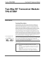
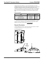
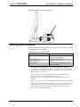
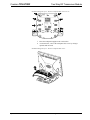
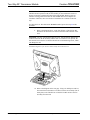
This document was prepared and written by the Technical Documentation department at:
Crestron Electronics, Inc.
15 Volvo Drive
Rockleigh, NJ 07647
1-888-CRESTRON
Crestron TPS-XTXRF
Two-Way RF Transceiver Module
Contents
Two-Way RF Transceiver Module: TPS-XTXRF
1
Description................................................................................................................................. 1
Functional Description ................................................................................................ 1
Physical Description.................................................................................................... 2
Leading Specifications............................................................................................................... 3
Installation ................................................................................................................................. 6
Setup ........................................................................................................................................ 14
Programming with SIMPL Windows........................................................................ 14
Configuring the Touchpanel for Operation ............................................................... 15
VT Pro-e Analog Join Number ................................................................................. 17
Operation ................................................................................................................................. 17
Problem Solving ...................................................................................................................... 18
Troubleshooting ........................................................................................................ 18
Further Inquiries........................................................................................................ 19
Future Updates .......................................................................................................... 19
Software License Agreement................................................................................................... 20
Return and Warranty Policies.................................................................................................. 22
Merchandise Returns / Repair Service ...................................................................... 22
CRESTRON Limited Warranty ................................................................................ 22
Operations & Installation Guide - DOC. 5844
Contents • i
Crestron TPS-XTXRF
Two-Way RF Transceiver Module
Two-Way RF Transceiver Module:
TPS-XTXRF
Description
Functional Description
The TPS-XTXRF Two-Way radio frequency (RF) Transceiver Module is an
optional feature designed for use with certain Crestron Isys™ tilt touchpanels
(TPS-5000, TPS-6000, and TPS-4500 – refer to note on this page for this unit).
Equipped with the TPS-XTXRF, the touchpanel is converted to an RF two-way
wireless transceiver that communicates through an RF gateway/transceiver, TPSRFGWX (sold separately) to the Crestron remote control system (herein referred to
as the Cresnet system). The two-way communications provide the control of
Crestron-controlled devices and provide dynamic onscreen feedback for real-time
confirmation of commands. Up to 15 touchpanels can communicate with one TPSRFGWX. The RF signals can travel from a minimum of three feet up to a maximum
of 150 feet. The location and the antenna position of the TPS-RFGWX are important
factors in the RF performance. The range of the touchpanel is also dependent on its
placement and the construction of the building in which it is used.
Crestron Identification Label
TPS-4500
ZA11323
C000000
NOTE: The TPS-XTXRF can be installed onto most TPS-4500 tilt touchpanels.
There is one version that cannot accept the two-way RF transceiver module. Refer to
the barcode label on the underside of the touchpanel base for identification.
TPS-4500 tilt touchpanels marked with number ZA11323 in the lower-left section
of the label are not compatible with the TPS-XTXRF.
Functional Summary
•
•
•
•
Operations & Installation Guide - DOC. 5844
Converts an Isys tilt touchpanel to an RF two-way wireless
transceiver
RF range is 3 to 150 feet depending on location and the surroundings
Up to 15 RF-enabled touchpanels can communicate with a single
TPS-RFGWX
Maintains sleek, ergonomic design and unique configuration
capabilities of the Isys panel (i.e., video, graphics, and Ethernet)
Two-Way RF Transceiver Module: TPS-XTXRF • 1
Crestron TPS-XTXRF
Two-Way RF Transceiver Module
Included with the TPS-XTXRF are a Crestron TPS-XBTP Battery Pack and a
TPS-XDS Docking Station. The TPS-XDS provides operating power for the docked
RF-enabled touchpanel and charges the TPS-XBTP when the battery pack is
installed in the touchpanel. An external power pack PW-2420RU is also supplied to
power the docking station/touchpanel and simultaneously charge the TPS-XBTP.
Refer to the table after this paragraph for the documentation supplied with these
items.
Related Documentation
*
ITEM
NOMENCLATURE
DOCUMENT
NUMBER *
Battery Pack
Docking Station
External Power Pack
TPS-XBTP
TPS-XDS
PW-2420RU
5845
5846
5892
Battery Pack Charger
TPS-XBC
6017
The latest revision may have a revision letter after the document number (i.e., 5845A).
The latest versions of the guides can be obtained from the Downloads | Product
Manuals section of the Crestron website (www.crestron.com).
Physical Description
The TPS-XTXRF, shown below, is housed in a black plastic enclosure. It replaces
the original touchpanel base cover on the panel enclosure.
TPS-XTXRF Physical Views
8.41 in
(21.36 cm)
7.78 in
(19.76 cm)
MAXIMUM
3.27 in
(8.31 cm)
9.85 in
(25.02 cm)
2 • Two-Way RF Transceiver Module: TPS-XTXRF
Operations & Installation Guide - DOC. 5844
Crestron TPS-XTXRF
Two-Way RF Transceiver Module
TPS-XTXRF Installed on Touchpanel (Side View)
Leading Specifications
The table below and continued on the next two pages provides a summary of leading
specifications for the TPS-XTXRF.
Leading Specifications of the TPS- XTXRF
SPECIFICATION
DETAILS
Compatible Touchpanels
Use with TPS-4500 (except ZA11323),
TPS-5000, and TPS-6000
Power Requirements
RF Transmitting Power
Communications
TPS-XBTP battery pack1
100 mW
Bidirectional Spread Spectrum 2.4 GHz
(2400 to 2483 MHz)
1
The ability of a TPS-XBTP to charge and hold a charge depends on a number of
variables such as which Isys panel is used and the number of expansion cards installed
in the touchpanel. The data provided here are worst and best-case scenarios to provide
an idea of what can be expected.
Charge Time (worst case): 12 hours for the TPS-6000 (all three cards installed)
Charge Time (best case): 3.5 hours for all units (power is off)
Battery Life (worst case): 2 hours (full brightness) for the TPS-6000 (all 3 cards
installed)
Battery Life (best case): 3.5 hours (full brightness) for the TPS-4500 (no cards installed)
In conclusion, the best condition for charging a battery is with the panel powered down.
Furthermore, the optimum operating conditions for extending battery charge requires
that the brightness be kept to a minimum, minimizing the standby and power down
timeouts, and avoid overheating/freezing.
Operations & Installation Guide - DOC. 5844
Two-Way RF Transceiver Module: TPS-XTXRF • 3
Two-Way RF Transceiver Module
Crestron TPS-XTXRF
Leading Specifications of the TPS- XTXRF (continued)
SPECIFICATION
DETAILS
Operating Ranges (line of sight)
Minimum Distance
Maximum Distance Indoor
Maximum Distance Outdoor
Operating Temperature
Charging Temperature
Storage Temperature
SIMPL™ Windows®
Crestron Database
IsysTM Touchpanel Firmware
2-Series Control System Update File 6
2
3 ft 2
150 ft 2
1000 ft
Approximately +32o to +104oF (0o to 40oC)
Approximately +50o to +95oF (10o to 35oC)
Approximately -4o to +113oF (-20o to 45oC)
Version 2.00.28 or later 3
Version 15.7.3 or later 3
Version 1.012.0 or later 4 & 5
Version C2-1008.CUZ or later 7 & 8
The location of the TPS-RFGWX and the orientation of the antenna are important
factors in the RF performance. With the unit located outside of any metal enclosures,
the antenna is adjusted to achieve the best range. The range is dependent on its
placement and the building in which it is used. The construction of the building,
obstructions and RF interference from other devices are factors determining the
effective range of the unit. To prevent unit-to-unit RF interference, multiple
gateway/transceivers operating at the same frequencies (TPS-RFGWXs and/or Crestron
CNRFGWXs) should not be installed within 3-5 feet of each other.
NOTE: Implementing multiple gateways (TPS-RFGWXs) to extend the range is not
permitted (i.e., no roaming).
3
The latest software version can be obtained from the Downloads | Software Updates
section of the Crestron website (www.crestron.com). Refer to NOTE after last footnote
on page 5.
4
The TPS-RFGWX and touchpanels with later versions of firmware may include features
not mentioned in this guide. Newer versions of this guide can be obtained from the
Downloads | Product Manuals section of the Crestron website (www.crestron.com).
5
The firmware upgrade files can be obtained from the Downloads | Software Updates
section of the Crestron website. Refer to NOTE after last footnote on page 5.
Crestron recommends that the latest firmware be loaded into the TPS-RFGWX and
associated touchpanel(s). When the firmware is upgraded, the touchpanel(s) firmware
must be upgraded at the same time.
6
Crestron 2-Series control systems consist of the AV2, AV2 with Card Cage, CP2,
CP2E, PAC2, PRO2, and RACK2
7
Filenames for 2-Series control system update files have a CUZ extension and can be
obtained from the Downloads | Software Updates section of the Crestron website
(www.crestron.com). New users are required to register in order to obtain access to the
FTP site.
8
When loading VT Pro-e files or firmware through the RS-232 port of the control
system, be sure that the baud rate is 57600 or lower. Otherwise, the Viewport may post
the “Transfer Failed” message. Higher baud rates (i.e., 115,000) can be selected, but
hardware handshaking (RTS/CTS) must be used.
4 • Two-Way RF Transceiver Module: TPS-XTXRF
Operations & Installation Guide - DOC. 5844
Crestron TPS-XTXRF
Two-Way RF Transceiver Module
Leading Specifications of the TPS- XTXRF (continued)
SPECIFICATION
DETAILS
CNMSX-AV/Pro Update File
CNRACKX/-DP Update File
CEN/CN-TVAV Update File
ST-CP Update File
Weight of TPS-XTXRF (no touchpanel)
Version 51020X.UPZ or later 8 & 9
Version 51020W.UPZ or later 8 & 9
Version 51205V.UPZ or later 8 & 9
Version 40104S.UPZ or later 9 & 10
Weight: 15.40 oz (0.44 kg) 11
9
CNX update files are required for either CNMSX-AV/Pro or CNRACKX/-DP.
Filenames for CNX update files have a UPZ extension and SmarTouch files are in one
EXE or zipped UPZ file. All can be obtained from the Downloads | Software Updates
section of the Crestron website. Refer to NOTE after last footnote.
10
Currently, the ST-CP does not support loading of firmware or VT Pro-e files to the
TPS-series panels through the RS-232 port of the control system.
Until there is a new ST-CP firmware release, these files can be loaded to the touchpanel
by either using the RS-232 port on the touchpanel or using Ethernet direct to the panel
(assuming the TPS-ENET is installed).
11
The weight listed DOES NOT include the TPS-XBTP Battery Pack, which weighs
2.2 lbs. (1.0 kg).
NOTE: Crestron software and any files on the FTP site are for Authorized Crestron
dealers only. New users may be required to register in order to obtain access to
certain areas of the FTP site.
NOTE: Equipment has been tested and found to comply with the limits for a Class
B digital device, pursuant to part 15 of the FCC Rules. These limits are designed to
provide reasonable protection against harmful interference in a residential
installation. The equipment generates, uses and can radiate radio frequency energy
and, if not installed and used in accordance with the instructions, may cause harmful
interference to radio communications. However, there is no guarantee that
interference will not occur in a particular installation. If this equipment does cause
harmful interference to radio or television reception, which can be determined by
turning the equipment off and on, the user is encouraged to try to correct the
interference by one or more of the following measures:
Reorient or relocate the receiving antenna.
Increase the separation between the equipment and receiver.
Connect the equipment into an outlet on a circuit different from that to which
the receiver is connected.
Consult the dealer or an experienced radio/TV technician for help.
As of the date of manufacture, the unit has been tested and found to comply with
specifications for CE marking and standards per EMC and Radiocommunications
Compliance Labelling (N11785).
Operations & Installation Guide - DOC. 5844
Two-Way RF Transceiver Module: TPS-XTXRF • 5
Two-Way RF Transceiver Module
Crestron TPS-XTXRF
Installation
The only tools required for installation of the TPS-XTXRF onto an Isys™ tilt
touchpanel are a #1 Phillips screwdriver and a grounding strap (or grounded
workstation).
CAUTION: The TPS-XTXRF and the touchpanel contain ESD sensitive devices.
Perform the following procedure while wearing a grounding strap that is properly
grounded or on a grounded work station to avoid damaging the card and/or the
touchpanel.
NOTE: If the angle of the touchscreen needs to be adjusted, consult latest revision
of the appropriate IsysTM tilt touchpanel operations guide for instructions of how to
use the touchpanel position lock buttons. The latest version of the operations guide
can be obtained from the Downloads | Product Manuals section of the Crestron
website (www.crestron.com).
NOTE: The diagrams in this procedure show a TPS-6000 but the steps for
installation of the previously listed TPS touchpanels are identical.
NOTE: If the TPS touchpanel is equipped with an optional TPS-XVGA or
TPS-XVGA-BV expansion card, temporarily removing the card makes installation
of the TPS-XTXRF cable connectors easier. However, re-installation of the card
requires a #1 Phillips screwdriver (1.5” length).
1.
If the optional external power pack is utilized with the touchpanel,
disconnect the power pack from the 24VDC 2.0A port on the rear of
the touchpanel base.
2.
Label and disconnect any cables attached to the ports on the rear of the
touchpanel base.
3.
If necessary, use the touchpanel position lock buttons to adjust the
touchscreen to the maximum (most vertical/upright) angle.
4.
To prevent scratching of the screen, place the touchpanel face-down
onto a padded surface.
5.
To prevent the touchpanel base cover from falling when the screws are
removed, hold the cover in place by hand.
6.
Refer to the diagram on the next page. Using a #1 Phillips screwdriver,
loosen, remove and retain the eight screws that secure the touchpanel
base cover.
6 • Two-Way RF Transceiver Module: TPS-XTXRF
Operations & Installation Guide - DOC. 5844
Crestron TPS-XTXRF
Two-Way RF Transceiver Module
Installation Diagram 1 of 12 - Remove Touchpanel Base Cover Screws
CLEAN PANEL WITH SOFT CLOTH ONLY
ELECTRONICS, INC
Rockleigh, NJ 07647
U.S.A.
READ INSTRUCTION MANUAL BEFORE OPERATING
NO USER SERVICABLE PARTS UNDER THIS COVER
ELECTRONICS, INC
Rockleigh, NJ 07647
U.S.A.
FCC ID: EROTPS-6000
SEE MANUAL
USE POWER PACK PW-2420RU
TPS-6000
ZA*****
C000000
7.
Place the touchpanel upright on the work surface.
8.
As shown below, remove the touchpanel base cover by raising it
upwards and rearward.
Installation Diagram 2 of 12 - Remove Touchpanel Base Cover
Operations & Installation Guide - DOC. 5844
Two-Way RF Transceiver Module: TPS-XTXRF • 7
Two-Way RF Transceiver Module
Crestron TPS-XTXRF
NOTE: If the TPS touchpanel is equipped with an optional TPS-XVGA or
TPS-XVGA-BV expansion card, the fan assembly on the card must be removed
because it interferes with the placement of the TPS-XTXRF. Removal will not
introduce cooling problems because the TPS-XTXRF has fans for adequate air
circulation. Therefore, there is no need to re-install the fan. Continue to the next
step.
If a TPS-XVGA or TPS-XVGA-BV IS NOT installed, proceed to step 11 of this
procedure.
9.
Refer to the diagram below. At the TPS-XVGA or TPS-XVGA-BV,
disconnect the fan electrical connector from the PCB connector of the
card.
CAUTION: An early generation the TPS-XVGA or TPS-XVGA-BV did not have a
connector between the fan assembly and the card. If a connector is not present, the
fan electrical wires must be cut flush to the PCB to avoid introducing a short, which
can damage the unit.
Installation Diagram 3 of 12 - Remove Fan Assembly Electrical Connector
10. Refer to the diagram on the next page. Using a #1 Phillips screwdriver,
loosen and remove the two screws that secure the fan assembly (fan on
metal plate) to the TPS-XVGA or TPS-XVGA-BV. Remove the fan
assembly from the card.
8 • Two-Way RF Transceiver Module: TPS-XTXRF
Operations & Installation Guide - DOC. 5844
Crestron TPS-XTXRF
Two-Way RF Transceiver Module
Installation Diagram 4 of 12 - Remove Mounting Screws & Fan Assembly
NOTE: If the TPS touchpanel is equipped with an optional TPS-XVGA or
TPS-XVGA-BV expansion card, temporarily removing the card makes installation
of the TPS-XTXRF cable connectors easier. However, re-installation of the card
requires a #1 Phillips screwdriver (1.5” length).
11. Refer to the diagram below. Position the TPS-XTXRF onto the
touchpanel as shown.
Installation Diagram 5 of 12 - Position TPS-XTXRF onto Touchpanel
Operations & Installation Guide - DOC. 5844
Two-Way RF Transceiver Module: TPS-XTXRF • 9
Two-Way RF Transceiver Module
Crestron TPS-XTXRF
12. Refer to the diagram below. Making sure that the RED wire at one end
of the large TPS-XTXRF connector faces in toward the center of the
unit, attach the TPS-XTXRF large connector to P11 (connector on the
touchpanel) so that all pins mate.
CAUTION: The touchpanel can be damaged when power is applied, if the large
TPS-XTXRF connector is mated incorrectly (any pin is exposed).
Installation Diagram 6 of 12 - Attach Large TPS-XTXRF Connector
RED
WIRE
13. Refer to the diagram below. To make final installation easier, spread
the wires of the large connector slightly apart.
Installation Diagram 7 of 12 - Spread Large Connector Wires
14. Refer to two diagrams on the next page. Making sure that the RED
STRIPE end of the ribbon cable faces in toward the center of the unit,
attach the TPS-XTXRF ribbon cable connector to P8 (connector on
the touchpanel).
NOTE: The TPS-XTXRF ribbon cable connector has a key to ensure a proper fit
with the small connector of the touchpanel. When installing the ribbon cable
connector, verify that the key slides into the slot of the mating connector.
10 • Two-Way RF Transceiver Module: TPS-XTXRF
Operations & Installation Guide - DOC. 5844
Crestron TPS-XTXRF
Two-Way RF Transceiver Module
Installation Diagram 8 of 12 - TPS-XTXRF Ribbon Cable Connector Detail
RED STRIPE
KEY
SLOT
Installation Diagram 9 of 12 - Attach TPS-XTXRF Ribbon Cable Connector
NOTE: If an optional TPS-XVGA or TPS-XVGA-BV expansion card was
temporarily removed to make installation of the TPS-XTXRF cable connectors
easier, re-install the card. Tighten the card mounting screws to finger-tight then
using a #1 Phillips screwdriver (1.5” length), tighten an additional 1/8-turn.
15. Refer to the diagram on the next page. Align the TPS-XTXRF threaded
screw inserts with the holes of the touchpanel base plate and lower the
TPS-XTXRF onto the touchpanel base.
Operations & Installation Guide - DOC. 5844
Two-Way RF Transceiver Module: TPS-XTXRF • 11
Crestron TPS-XTXRF
Two-Way RF Transceiver Module
Installation Diagram 10 of 12 - Lower TPS-XTXRF onto Touchpanel Base
16. Hold the TPS-XTXRF in place and position the touchpanel face-down
onto a padded surface to prevent scratching of the screen.
17. Refer to the diagram below. Re-install the eight base cover screws to
finger-tight then, using a #1 Phillips screwdriver, tighten an additional
1/8-turn.
Installation Diagram 11 of 12 - Install TPS-XTXRF Mounting Screws
CLEAN PANEL WITH SOFT CLOTH ONLY
ELECTRONICS, INC
Rockleigh, NJ 07647
U.S.A.
READ INSTRUCTION MANUAL BEFORE OPERATING
NO USER SERVICABLE PARTS UNDER THIS COVER
ELECTRONICS, INC
Rockleigh, NJ 07647
U.S.A.
FCC ID: EROTPS-6000
SEE MANUAL
USE POWER PACK PW-2420RU
TPS-6000
ZA*****
C000000
18. Place the touchpanel upright on the work surface.
12 • Two-Way RF Transceiver Module: TPS-XTXRF
Operations & Installation Guide - DOC. 5844
Crestron TPS-XTXRF
Two-Way RF Transceiver Module
19. Refer to the diagram below. By hand, thread the antenna onto the
antenna mounting post to finger-tight.
Installation Diagram 12 of 12 - Install Antenna
20. Apply power to the touchpanel.
There are four ways to operate the TPS-XTXRF equipped touchpanel.
First, a charged TPS-XBTP Battery Pack can be installed into the
touchpanel directly. Secondly, the TPS-XTXRF equipped touchpanel
can be properly positioned on the TPS-XDS Docking Station with or
without a TPS-XBTP installed. The touchpanel can also be powered
directly via the PW-2420RU (without a docking station). Finally, the
unit can be powered via a Cresnet connection. However, keep in mind
that a Cresnet connection disables the RF communication capabilities
of the unit; the panel continues to operate as a wired touchpanel if it is
correctly defined in the SIMPL program. Power must be re-applied
using one of the first three mentioned methods to take advantage of RF
communication.
NOTE: For further information about the TPS-XBTP and TPS-XDS, consult their
Operations Guide (Doc. 5845 and 5846, respectively). The latest versions of the
guides can be obtained from the Downloads | Product Manuals section of the
Crestron website (www.crestron.com).
Operations & Installation Guide - DOC. 5844
Two-Way RF Transceiver Module: TPS-XTXRF • 13
Crestron TPS-XTXRF
Two-Way RF Transceiver Module
Setup
Programming with SIMPL Windows
SIMPL (Symbol Intensive Master Programming Language) is an easy-to-use
programming language that is completely integrated and compatible with all
Crestron system hardware. The objects that are used in SIMPL are called symbols.
SIMPL Windows offers drag and drop functionality in a familiar Windows®
environment.
SIMPL Windows is Crestron's software for programming Crestron control systems.
It provides a well-designed graphical environment with a number of workspaces
(i.e., windows) in which a programmer can select, configure, program, test, and
monitor a Crestron control system.
The next two sections describe a TPS-XTXRF within SIMPL Windows. The first
section provides initial configuration information and the second section provides
the location of example programs.
NOTE: The following descriptions assume that the reader has knowledge of
SIMPL Windows. If not, refer to the extensive help information provided with the
software.
NOTE: To minimize system diagnostics and troubleshooting, Crestron recommends
defining the touchpanel as a wired unit in SIMPL Windows, then test functionality
as a wired network device prior to testing the TPS-XTXRF transceiver operations.
This will help in determining whether there is a programming problem, RF setting
conflict or RF interference in the environment.
Configure TPS-XTXRF Equipped Touchpanel
To create a program with a TPS-XTXRF, refer to the table below for initial
configuration information.
Configure TPS-XTXRF Program
SYMBOL
FOLDER
SYMBOL
REQUIRED
DROP
WHERE
ADDITIONAL
SETUP
Device Library,
Control
Systems
Desired control System Views Refer to the documentation
system
supplied with the specific control
system for additional setup
information.
Device Library, TPS-RFGWX System Views, CHANGE NET ID (OPTIONAL) Wireless
Cresnet Units Double-click on TPS-RFGWX (or
Receivers,
single-click then right mouseclick). Select Configure. Select
Wireless
NET ID then select desired
Receivers (RF)
hexadecimal ID.
Device Library,
Touchpanels,
Touchpanels
(Wireless TwoWay)
TPS-4500 w/ System Views,
TPS-XTXRF, TPS-RFGWX
TPS-5000 w/
TPS-XTXRF,
or TPS-6000 w/
TPS-XTXRF.
14 • Two-Way RF Transceiver Module: TPS-XTXRF
CHANGE RF ID (OPTIONAL) Single-click on TPS-RFGWX. In
the System Views Detail Window,
double-click (or single-click then
right mouse-click, select
Configure) on name of touchpanel in TPSRF Address text
window. Select Configure.
Select RF ID then select desired
hexadecimal ID.
Operations & Installation Guide - DOC. 5844
Crestron TPS-XTXRF
Two-Way RF Transceiver Module
NOTE: Commenting out the Cresnet ID of the RF receiver in the SIMPL Windows
program will allow only Cresnet (wired touchpanel) use of the TPS-XTXRF
equipped touchpanel.
To configure a TPS-RFGWX Two-Way RF Transceiver (sold separately), refer to
the latest revision of the TPS-RFGWX Operations & Installation Guide (Doc. 5847).
This document can be obtained from the Downloads | Product Manuals section of
the Crestron website (www.crestron.com).
Example Program
The TPS-XTXRF equipped touchpanel communicates to a TPS-RFGWX Two-Way
RF Transceiver (sold separately) that resides on the Cresnet system. The
TPS-XTXRF equipped touchpanel and TPS-RFGWX may be programmed similar to
(operating frequencies are not compatible) the STRFGWX Two-Way RF
Transceiver and STX-1550C two-way wireless RF touchpanel. For an example
program, refer to the program for the STX-1550C which is available from the
Crestron FTP site (www.ftp.crestron.com). Select the Examples folder and search
for STX1550C_*.SMW.
Configuring the Touchpanel for Operation
The touchpanel with the TPS-XTXRF installed can operate as a Cresnet or RF
device. The operation of the touchpanel is determined by the attachment of the
NET/VIDEO cable to the touchpanel. To use the touchpanel as a Cresnet wired unit,
connect the NET/VIDEO cable to the NET/VIDEO port of the touchpanel. To use
the touchpanel as an RF unit, disconnect the cable from the touchpanel. In summary,
the RF-enabled touchpanel can only operate in one mode of operation at a time and
the mode is determined by whether a connection is made at the NET/VIDEO port.
NOTE: If the intent is to use the touchpanel in both modes, Crestron recommends
that the programmer does not comment out the Cresnet ID of the touchpanel in the
SIMPL Windows program. If the ID is commented out, the touchpanel will cease to
operate when the NET/VIDEO cable is connected. Operation can resume when all
power is disconnected and re-applied.
To configure the unit, it may be necessary to access a series of setup screens prior to
viewing run-time screens that are loaded into the touchpanel for normal Cresnet or
RF operation. The next two sections provide details regarding configuration of the
touchpanel for both modes of operation.
Cresnet Configuration
For configuration of the touchpanel with respect to Cresnet mode of operation,
consult the appropriate IsysTM tilt touchpanel operations guide. This document can
be obtained from the Downloads | Product Manuals section of the Crestron website
(www.crestron.com). It provides details about setting the Cresnet ID of the
touchpanel as well as setting up the touchpanel for Ethernet or RS-232
communication, displaying computer-generated video format (RGB) and video from
up to two different sources, adjusting audio controls, and selecting personal setting
for screen brightness and timeouts.
Operations & Installation Guide - DOC. 5844
Two-Way RF Transceiver Module: TPS-XTXRF • 15
Two-Way RF Transceiver Module
Crestron TPS-XTXRF
RF Configuration
Crestron IsysTM tilt touchpanel are default configured for Cresnet (wired) operation.
To configure the TPS-XTXRF equipped touchpanel for RF communication, it is
necessary to access a series of setup screens on the touchpanel.
NOTE: For additional touchpanel configuration information, consult the
appropriate IsysTM tilt touchpanel operations guide. This document can be obtained
from the Downloads | Product Manuals section of the Crestron website
(www.crestron.com).
1.
The Main Menu for configuring the touchpanel appears when a finger
is held to the touchscreen as power is applied. Remove your finger
after approximately 3 to 5 seconds when the message “SETUP MODE”
appears on the touchscreen.
2.
On Main Menu screen, select the Setup button.
3.
On Setup Menu, select the Interface button.
4.
Refer to the diagram below for the next four steps.
Interface Menu
5.
On Interface Menu, select the RF Enable button.
NOTE: To ensure communication between the TPS-RFGWX and RF-enabled
touchpanel, distinct types of identification codes are required. . For additional RF ID
and RF CHANNEL information, consult the TPS-RFGWX Operations &
Installation Guide (Doc. 5847). This document can be obtained from the Downloads
| Product Manuals section of the Crestron website (www.crestron.com).
NOTE: An error occurs if two or more RF-enabled panels share the same RF ID.
The first panel with the shared RF ID to successfully transmit to the TPS-RFGWX
maintains communication, but locks out the other panels.
6.
The RF ID is important because it allows a number (up to 15) of
touchpanels to communicate to a Cresnet system/SIMPL program via
one TPS-RFGWX. If more than 15 touchpanels are required within the
system, additional TPS-RFGWXs with a different RF ID must be
added. These codes, which range from 01 to 0F are selected from this
menu and must match the ID assigned via Crestron software. Press RF
16 • Two-Way RF Transceiver Module: TPS-XTXRF
Operations & Installation Guide - DOC. 5844
Crestron TPS-XTXRF
Two-Way RF Transceiver Module
ID DOWN or UP button to select the RF ID that was assigned to the
touchpanel in “Programming with SIMPL Windows”.
7.
The RF CHANNEL is important because it allows the radio in a
touchpanel to communicate with the radio in the TPS-RFGWX. If the
RF CHANNELs match, the RF-enabled panel can communicate to the
system via the pre-defined frequency channel. These codes, which
range from 0 to F are selected from this menu and must match the ID
assigned via Crestron software. Press RF CHANNEL DOWN or UP
button to set the RF CHANNEL. The RF CHANNEL must match the
RF CHANNEL of the TPS-RFGWX that was assigned with Viewport.
8.
Select the Save and Return button to return to Main Menu.
9.
On Main Menu, select the Exit and Run Program button.
VT Pro-e Analog Join Number
A join number is a feature of the VT Pro-e that enables a designer to create a button,
slider or gauge on a touchpanel page that completes a predetermined function. For
the TPS-XTXRF equipped touchpanel, analog join number 17507 may be used for a
TPS-BTP battery gauge. There is also another analog join number 17514 that is used
to determine the state of the battery pack. The response is a number that ranges from
0 to 4 and each value is defined as follows.
•
0 – Battery Not Installed:
Battery is not installed or seated properly.
•
1 – Battery Discharging
Battery is detected, but no charging action is being taken. Battery
powers the RF-enabled panel while battery is discharging.
•
2 – Battery Charging:
Battery is fast charging at the maximum possible current (up to
approximately 1.5 A).
•
3 – Battery Full
Battery has finished charging.
•
4 –Battery Slow Charging
Battery is charging in slow charging mode.
NOTE: Upon power up, the battery level and battery state gauges that utilize these
analog join numbers may take up to one minute to update.
Operation
A TPS-XTXRF equipped touchpanel operates the same as a Cresnet (wired)
touchpanel but with the following considerations.
WARNING: To avoid shock hazard and possible damage to the unit, do not use
touchpanel in rain or expose it to unnecessary moisture.
CAUTION: The fans located within the sides of the TPS-XTXRF Module provide
cooling air for the touchpanel. To prevent excessive internal temperature when
operating the touchpanel, do not cover the side fan intakes.
Operations & Installation Guide - DOC. 5844
Two-Way RF Transceiver Module: TPS-XTXRF • 17
Crestron TPS-XTXRF
Two-Way RF Transceiver Module
NOTE: Once configured for Cresnet and RF operation, the function of the
touchpanel is determined by the attachment of the NET/VIDEO cable to the
touchpanel. To use the touchpanel as a Cresnet wired unit, connect the NET/VIDEO
cable to the NET/VIDEO port of the touchpanel. To use the touchpanel as an RF
unit, disconnect the cable from the touchpanel.
NOTE: Touchpanel wake-up from standby mode may take 2-5 seconds. This slight
delay allows the radio transceivers to communicate and enables the program to
update.
Problem Solving
Troubleshooting
The table below provides corrective action for possible trouble situations. If further
assistance is required, please contact a Crestron customer service representative.
NOTE: To minimize system diagnostics and troubleshooting, Crestron recommends
defining the touchpanel as a wired unit in SIMPL Windows, then test functionality
as a wired network device prior to testing the TPS-XTXRF transceiver operations.
This will help in determining whether there is a programming problem, RF setting
conflict or RF interference in the environment.
TPS-XTXRF Troubleshooting
TROUBLE
POSSIBLE
CAUSE(S)
CORRECTIVE ACTION
Touchpanel(s) does TPS-XBTP battery Position the touchpanel onto the
TPS-XDS docking station to charge the
pack has low
not communicate
1 charge.
TPS-XBTP battery pack or to "hot swap"
with control system.
battery pack.
Touchpanel is out Position the touchpanel to within
of range.
operating range or relocate TPS-RFGWX.
Refer to "Leading Specifications" on page
3 for details.
Touchpanel is set Refer to the "Setup" section of this guide
to verify that touchpanel RF Channel is
to wrong RF
set to match the TPS-RFGWX RF
Channel.
Channel.
Touchpanel RF ID Verify that the RF ID for the touchpanel
does not match the then refer to the "Setup" section of this
guide to set the touchpanel RF ID to
RF ID of the
match RF ID in SIMPL program.
SIMPL program.
Problem with TPS- Refer to the "Troubleshooting" section of
RFGWX.
the Operations & Installation Guide for the
TPS-RFGWX. 2
1
To determine a possible cause, verify that the SIG LED on the TPS-RFGWX illuminates when a
button is pressed on the touchscreen. Illumination indicates a power or range related problem. No
illumination indicates a programming related problem. If there are multiple RF-enabled toucpanels in
the system, each one must be tested separately.
18 • Two-Way RF Transceiver Module: TPS-XTXRF
Operations & Installation Guide - DOC. 5844
Crestron TPS-XTXRF
Two-Way RF Transceiver Module
TPS-XTXRF Troubleshooting (continued)
TROUBLE
POSSIBLE
CAUSE(S)
CORRECTIVE ACTION
TPS-XBTP battery Position the touchpanel onto the
TPS-XDS docking station to charge the
pack has low
TPS-XBTP battery pack or to "hot swap"
charge.
battery pack.
Touchpanel is in
Verify that large amount of metal is not in
vicinity of metal.
vicinity of transmission.
Touchpanel is too Position the touchpanel to within
operating range. Refer to "Leading
close to TPSSpecifications" on page 3 for details.
RFGWX.
Multiple touchpanels Multiple
Refer to the "Setup" section of this guide
only operate one at a touchpanels are
to verify that touchpanel RF Channel is
set to match the TPS-RFGWX RF
set to same RF
time. 3
Channel.
Channel RF ID.
Intermittent response
from TPS-RFGWX
during
communication with
touchpanel.
Various.
RF-enabled
touchpanel 'locks up'
or displays a black or
white screen.
Disconnect all power sources and remove
battery. Reapply power.
2
The latest revision of the Operations & Installation Guide for the TPS-RFGWX Two-Way RF
Transceiver (Doc. 5847) can be obtained from the Downloads | Product Manuals section of the
Crestron website (www.crestron.com).
3
Additional symptoms of multiple touchpanels with the same RF Channel & RF ID would be the first
touchpanel to transmit & receive is functional. The second or subsequent touchpanel(s) will not
function unless the first touchpanel is out of operating range or powered-down.
Further Inquiries
If after reviewing this Operations & Installation Guide, you cannot locate specific
information or have questions, please take advantage of Crestron's award winning
customer service team by calling:
•
In the US and Canada, call Crestron’s corporate headquarters at
1-888-CRESTRON [1-888-273-7876] or 1-201-767-3400.
•
In Europe, call Crestron International at +32-15-50-99-50.
•
In Asia, call Crestron Asia at +852-2341-2016.
•
In Latin America, call Crestron Latin America at +5255-5093-2160.
•
In Australia and New Zealand, call Crestron Pacific at
+613-9480-2999.
Future Updates
As Crestron improves functions, adds new features, and extends the capabilities of
the TPS-XTXRF, additional information may be made available as manual updates.
These updates are solely electronic and serve as intermediary supplements prior to
the release of a complete technical documentation revision.
The Downloads section of the Crestron website (www.crestron.com) directs the
reader to the location and description of each update. Check the site periodically for
update availability and its subjective value.
Operations & Installation Guide - DOC. 5844
Two-Way RF Transceiver Module: TPS-XTXRF • 19
Two-Way RF Transceiver Module
Crestron TPS-XTXRF
Software License Agreement
This License Agreement (“Agreement”) is a legal contract between you (either an individual or a single business entity) and
Crestron Electronics, Inc. (“Crestron”) for software referenced in this guide, which includes computer software and, as applicable,
associated media, printed materials, and “online” or electronic documentation (the “Software”).
BY INSTALLING, COPYING, OR OTHERWISE USING THE SOFTWARE, YOU REPRESENT THAT YOU ARE AN
AUTHORIZED DEALER OF CRESTRON PRODUCTS OR A CRESTRON AUTHORIZED INDEPENDENT PROGRAMMER
AND YOU AGREE TO BE BOUND BY THE TERMS OF THIS AGREEMENT. IF YOU DO NOT AGREE TO THE TERMS OF
THIS AGREEMENT, DO NOT INSTALL OR USE THE SOFTWARE.
IF YOU HAVE PAID A FEE FOR THIS LICENSE AND DO NOT ACCEPT THE TERMS OF THIS AGREEMENT,
CRESTRON WILL REFUND THE FEE TO YOU PROVIDED YOU (1) CLICK THE DO NOT ACCEPT BUTTON, (2) DO NOT
INSTALL THE SOFTWARE AND (3) RETURN ALL SOFTWARE, MEDIA AND OTHER DOCUMENTATION AND
MATERIALS PROVIDED WITH THE SOFTWARE TO CRESTRON AT: CRESTRON ELECTRONICS, INC., 15 VOLVO
DRIVE, ROCKLEIGH, NEW JERSEY 07647, WITHIN 30 DAYS OF PAYMENT.
LICENSE TERMS
Crestron hereby grants You and You accept a nonexclusive, nontransferable license to use the Software (a) in machine
readable object code together with the related explanatory written materials provided by Creston (b) on a central processing unit
(“CPU”) owned or leased or otherwise controlled exclusively by You, and (c) only as authorized in this Agreement and the related
explanatory files and written materials provided by Crestron.
If this software requires payment for a license, you may make one backup copy of the Software, provided Your backup
copy is not installed or used on any CPU. You may not transfer the rights of this Agreement to a backup copy unless the installed
copy of the Software is destroyed or otherwise inoperable and You transfer all rights in the Software.
You may not transfer the license granted pursuant to this Agreement or assign this Agreement without the express written
consent of Crestron.
If this software requires payment for a license, the total number of CPU’s on which all versions of the Software are installed
may not exceed one per license fee (1) and no concurrent, server or network use of the Software (including any permitted back-up
copies) is permitted, including but not limited to using the Software (a) either directly or through commands, data or instructions from
or to another computer (b) for local, campus or wide area network, internet or web hosting services; or (c) pursuant to any rental,
sharing or “service bureau” arrangement.
The Software is designed as a software development and customization tool. As such Crestron cannot and does not
guarantee any results of use of the Software or that the Software will operate error free and You acknowledge that any development
that You perform using the Software or Host Application is done entirely at Your own risk.
The Software is licensed and not sold. Crestron retains ownership of the Software and all copies of the Software and
reserves all rights not expressly granted in writing.
OTHER LIMITATIONS
You must be an Authorized Dealer of Crestron products or a Crestron Authorized Independent Programmer to install or use
the Software. If Your status as a Crestron Authorized Dealer or Crestron Authorized Independent Programmer is terminated, Your
license is also terminated.
You may not rent, lease, lend, sublicense, distribute or otherwise transfer or assign any interest in or to the Software.
You may not reverse engineer, decompile, or disassemble the Software.
You agree that the Software will not be shipped, transferred or exported into any country or used in any manner prohibited
by the United States Export Administration Act or any other export laws, restrictions or regulations (“Export Laws”). By downloading
or installing the Software You (a) are certifying that You are not a national of Cuba, Iran, Iraq, Libya, North Korea, Sudan, or Syria or
any country to which the United States embargoes goods (b) are certifying that You are not otherwise prohibited from receiving the
Software and (c) You agree to comply with the Export Laws.
If any part of this Agreement is found void and unenforceable, it will not affect the validity of the balance of the
Agreement, which shall remain valid and enforceable according to its terms. This Agreement may only be modified by a writing
signed by an authorized officer of Crestron. Updates may be licensed to You by Crestron with additional or different terms. This is
the entire agreement between Crestron and You relating to the Software and it supersedes any prior representations, discussions,
undertakings, communications or advertising relating to the Software. The failure of either party to enforce any right or take any
action in the event of a breach hereunder shall constitute a waiver unless expressly acknowledged and set forth in writing by the party
alleged to have provided such waiver.
20 • Two-Way RF Transceiver Module: TPS-XTXRF
Operations & Installation Guide - DOC. 5844
Crestron TPS-XTXRF
Two-Way RF Transceiver Module
If You are a business or organization, You agree that upon request from Crestron or its authorized agent, You will within
thirty (30) days fully document and certify that use of any and all Software at the time of the request is in conformity with Your valid
licenses from Crestron of its authorized agent.
Without prejudice to any other rights, Crestron may terminate this Agreement immediately upon notice if you fail to comply
with the terms and conditions of this Agreement. In such event, you must destroy all copies of the Software and all of its component
parts.
PROPRIETARY RIGHTS
Copyright. All title and copyrights in and to the Software (including, without limitation, any images, photographs,
animations, video, audio, music, text, and “applets” incorporated into the Software), the accompanying media and printed materials,
and any copies of the Software are owned by Crestron or its suppliers. The Software is protected by copyright laws and international
treaty provisions. Therefore, you must treat the Software like any other copyrighted material, subject to the provisions of this
Agreement.
Submissions. Should you decide to transmit to Crestron’s website by any means or by any media any materials or other
information (including, without limitation, ideas, concepts or techniques for new or improved services and products), whether as
information, feedback, data, questions, comments, suggestions or the like, you agree such submissions are unrestricted and shall be
deemed non-confidential and you automatically grant Crestron and its assigns a non-exclusive, royalty-tree, worldwide, perpetual,
irrevocable license, with the right to sublicense, to use, copy, transmit, distribute, create derivative works of, display and perform the
same.
Trademarks. CRESTRON and the Swirl Logo are registered trademarks of Crestron Electronics, Inc. You shall not remove
or conceal any trademark or proprietary notice of Crestron from the Software including any back-up copy.
GOVERNING LAW
This Agreement shall be governed by the laws of the State of New Jersey, without regard to conflicts of laws principles.
Any disputes between the parties to the Agreement shall be brought in the state courts in Bergen County, New Jersey or the federal
courts located in the District of New Jersey. The United Nations Convention on Contracts for the International Sale of Goods, shall not
apply to this Agreement.
CRESTRON LIMITED WARRANTY
CRESTRON warrants that: (a) the Software will perform substantially in accordance with the published specifications for a
period of ninety (90) days from the date of receipt, and (b) that any hardware accompanying the Software will be subject to its own
limited warranty as stated in its accompanying written material. Crestron shall, at its option, repair or replace or refund the license fee
for any Software found defective by Crestron if notified by you within the warranty period. The foregoing remedy shall be your
exclusive remedy for any claim or loss arising from the Software.
CRESTRON shall not be liable to honor warranty terms if the product has been used in any application other than that for
which it was intended, or if it as been subjected to misuse, accidental damage, modification, or improper installation procedures.
Furthermore, this warranty does not cover any product that has had the serial number or license code altered, defaced, improperly
obtained, or removed.
Notwithstanding any agreement to maintain or correct errors or defects Crestron, shall have no obligation to service or
correct any error or defect that is not reproducible by Crestron or is deemed in Crestron’s reasonable discretion to have resulted from
(1) accident; unusual stress; neglect; misuse; failure of electric power, operation of the Software with other media not meeting or not
maintained in accordance with the manufacturer’s specifications; or causes other than ordinary use; (2) improper installation by
anyone other than Crestron or its authorized agents of the Software that deviates from any operating procedures established by
Crestron in the material and files provided to You by Crestron or its authorized agent; (3) use of the Software on unauthorized
hardware; or (4) modification of, alteration of, or additions to the Software undertaken by persons other than Crestron or Crestron’s
authorized agents.
ANY LIABILITY OF CRESTRON FOR A DEFECTIVE COPY OF THE SOFTWARE WILL BE LIMITED
EXCLUSIVELY TO REPAIR OR REPLACEMENT OF YOUR COPY OF THE SOFTWARE WITH ANOTHER COPY OR
REFUND OF THE INITIAL LICENSE FEE CRESTRON RECEIVED FROM YOU FOR THE DEFECTIVE COPY OF THE
PRODUCT. THIS WARRANTY SHALL BE THE SOLE AND EXCLUSIVE REMEDY TO YOU. IN NO EVENT SHALL
CRESTRON BE LIABLE FOR INCIDENTAL, CONSEQUENTIAL, SPECIAL OR PUNITIVE DAMAGES OF ANY KIND
(PROPERTY OR ECONOMIC DAMAGES INCLUSIVE), EVEN IF A CRESTRON REPRESENTATIVE HAS BEEN ADVISED
OF THE POSSIBILITY OF SUCH DAMAGES OR OF ANY CLAIM BY ANY THIRD PARTY. CRESTRON MAKES NO
WARRANTIES, EXPRESS OR IMPLIED, AS TO TITLE OR INFRINGEMENT OF THIRD-PARTY RIGHTS,
MERCHANTABILITY OR FITNESS FOR ANY PARTICULAR PURPOSE, OR ANY OTHER WARRANTIES, NOR
AUTHORIZES ANY OTHER PARTY TO OFFER ANY WARRANTIES, INCLUDING WARRANTIES OF
MERCHANTABILITY FOR THIS PRODUCT. THIS WARRANTY STATEMENT SUPERSEDES ALL PREVIOUS
WARRANTIES.
Operations & Installation Guide - DOC. 5844
Two-Way RF Transceiver Module: TPS-XTXRF • 21
Crestron TPS-XTXRF
Two-Way RF Transceiver Module
Return and Warranty Policies
Merchandise Returns / Repair Service
1.
No merchandise may be returned for credit, exchange, or service without prior authorization
from CRESTRON. To obtain warranty service for CRESTRON products, contact the factory
and request an RMA (Return Merchandise Authorization) number. Enclose a note specifying
the nature of the problem, name and phone number of contact person, RMA number, and
return address.
2.
Products may be returned for credit, exchange, or service with a CRESTRON Return
Merchandise Authorization (RMA) number. Authorized returns must be shipped freight
prepaid to CRESTRON, Cresskill, N.J., or its authorized subsidiaries, with RMA number
clearly marked on the outside of all cartons. Shipments arriving freight collect or without an
RMA number shall be subject to refusal. CRESTRON reserves the right in its sole and
absolute discretion to charge a 15% restocking fee, plus shipping costs, on any products
returned with an RMA.
3.
Return freight charges following repair of items under warranty shall be paid by
CRESTRON, shipping by standard ground carrier. In the event repairs are found to be nonwarranty, return freight costs shall be paid by the purchaser.
CRESTRON Limited Warranty
CRESTRON ELECTRONICS, Inc. warrants its products to be free from manufacturing defects in
materials and workmanship under normal use for a period of three (3) years from the date of
purchase from CRESTRON, with the following exceptions: disk drives and any other moving or
rotating mechanical parts, pan/tilt heads and power supplies are covered for a period of one (1)
year; touchscreen display and overlay components are covered for 90 days; batteries and
incandescent lamps are not covered.
This warranty extends to products purchased directly from CRESTRON or an authorized
CRESTRON dealer. Purchasers should inquire of the dealer regarding the nature and extent of the
dealer's warranty, if any.
CRESTRON shall not be liable to honor the terms of this warranty if the product has been used in
any application other than that for which it was intended, or if it has been subjected to misuse,
accidental damage, modification, or improper installation procedures. Furthermore, this warranty
does not cover any product that has had the serial number altered, defaced, or removed.
This warranty shall be the sole and exclusive remedy to the original purchaser. In no event shall
CRESTRON be liable for incidental or consequential damages of any kind (property or economic
damages inclusive) arising from the sale or use of this equipment. CRESTRON is not liable for
any claim made by a third party or made by the purchaser for a third party.
CRESTRON shall, at its option, repair or replace any product found defective, without charge for
parts or labor. Repaired or replaced equipment and parts supplied under this warranty shall be
covered only by the unexpired portion of the warranty.
Except as expressly set forth in this warranty, CRESTRON makes no other warranties, expressed
or implied, nor authorizes any other party to offer any other party to offer any warranty, including
any implied warranties of merchantability or fitness for a particular purpose. Any implied
warranties that may be imposed by law are limited to the terms of this limited warranty. This
warranty statement supercedes all previous warranties.
Trademark Information
All brand names, product names, and trademarks are the sole property of their respective owners. Windows is a registered
trademark of Microsoft Corporation. Windows95/98/Me/XP and WindowsNT/2000 are trademarks of Microsoft
Corporation
22 • Two-Way RF Transceiver Module: TPS-XTXRF
Operations & Installation Guide - DOC. 5844
Crestron TPS-XTXRF
Two-Way RF Transceiver Module
This page intentionally left blank.
Operations & Installation Guide - DOC. 5844
Two-Way RF Transceiver Module: TPS-XTXRF • 23
Crestron Electronics, Inc.
15 Volvo Drive Rockleigh, NJ 07647
Tel: 888.CRESTRON
Fax: 201.767.7576
www.crestron.com
Operations & Installation Guide - DOC. 5844
03.02
Specifications subject to
change without notice.