1
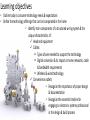
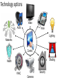
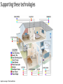
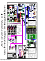
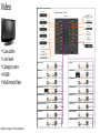
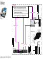
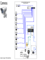
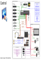
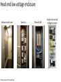
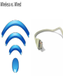
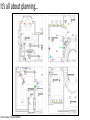
Wiring Requirements to Support Electronic Systems AIA Provider #G251 AIA course #CIO035 Credit(s) earned on completion of this course will be reported to AIA CES members. Certificates of Completion for both AIA members and non-AIA members are available upon request. This course is registered with the AIA CES for continuing professional education. As such, it does not include content that may be deemed or construed to be an approval or endorsement by the AIA of any material of construction or any method or manner of handling, using, distributing, or dealing in any material or product. Questions related to specific materials, methods, and services will be addressed at the conclusion of this presentation. Course Description Supporting the multitude of technologies found in today’s connected homes requires planning, specialized installation, and a solid infrastructure in place. Attendees will discuss the trends and future technologies and their impact on today’s homes, as well as be made aware of the basic infrastructure requirements needed to support these technologies so that they perform at maximum capacity. Participants will be able to define the components of a structured wiring system and list the benefits that correctly installed systems offer to their clients’ technology needs. Attendees will also engage in discussion related to partnering with a trained electronics professional in the planning and installation of these complex systems. This CEU is registered with the Interior Design Continuing Education Council (IDCEC) for continuing education credits. This credit will be accepted by the American Society of Interior Designers (ASID), International Interior Designers Association (IIDA) and Interior Designers of Canada (IDC). The content included is not deemed or construed to be an approval or endorsement by IDCEC of any material or construction or any method or manner of handling, using, distributing or dealing in any material or product. Questions related to specific materials, methods and services should be directed to the instructor or provider of this CEU. This program is registered for 0.1 CEU value. The IDCEC class-code will be provided by the instructor. This CEU will be reported on your behalf to IDCEC and you will receive an email notification. Please log in and complete the electronic survey for this CEU. Certificates of completion will be automatically issued once you have submitted the online survey for this CEU. Attendees who do not belong to ASID, IIDA or IDC and do not have a unique IDCEC number will be provided with a Certificate of Completion after this CEU. Learning objectives • Outline today's consumer technology needs & expectations • Define the technology offerings that can be incorporated in the home • Identify main components of a structured wiring system & the unique characteristics of: Head end equipment Cables: Types of wire needed to support the technology Digital conversion & its impact on home networks, cable & bandwidth requirements Wireless & wired technology Convenience outlets • Recognize the importance of proper design & documentation • Recognize the essential timeline for engaging an electronic systems professional in the design & build process We all use technology every day… Smartphones and devices Cars Photo courtesy of CBS Interactive What technologies do clients expect in their homes? Photo courtesy of Insight Home Solutions Technology options Video Audio Voice Lighting Networks Control Shading Health HVAC Security Cameras Supporting these technologies Graphic courtesy of The Sound Room Connectivity Block Diagram TPS-6L Camera Surveillance System Security System Crestron Touchpanel Camera Distribution An overview of technology integration Typical Video Crestron Touchpanels – up to 32 Video Zones – Port A CNXRMCLV Front & Audio Installation with Control Options IR Emitter Cat Qty : 1 C 2 N - IVDS 568 Installed - A Pattern Cascaded Composite Equipment Rack Video Display Cat HTFS 1000 5 Video Distributon to Equipment Rack PVID Typical connections System at each TV Location . Power Supply 120 VAC Power Supply 120 VAC Camera Access will be available in three ways to a user : Selectable thru a Web Browser on any computer using an intranet Internet Explorer address . 2. On a Crestron Touchpanel selectable for any camera at any time at any Touchpanel. Multi-View format. 3. One selectable Global Camera view is available to all TV’s at one time. This one global camera view is selectable by either a Crestron Touchpanel or Crestron Wireless Remote . Camera Videos Key Digital KD-VP6 TV Output Convertor 22 /4 To Crestron 1. CNXRMCLV Rear Componet Cable To TV input Type to TBD Qty : 46 Qty : 2 HAI Security Panel 5 e Cable To Touchpanels Cresnet to Touchpanels Speco DVR - 8 TN 8 Channel DVR Flush Glass Break Sensors Ethernet 18 /4 Or 16 /2 Zone 14 Air Duct Sensor Fire/Heat Ceiling Sensor 18 /4 Qty : 4 Qty : 2 Composite 18 /2 Composite DVR Camera Camera Videos Selectable 22 /4 22 / 4 To Speco Camera DVR Output to Qty : 7 Key Digital Crestron W ireless Control Option Types Crestron Touchpanel Crestron Keypad Remote Cat 5e 568-A For W ireless Remotes Cisco 1100 W AP for W ireless Status Modules Cameras Qty : 8 Component Video To House TV’s Room Speakers Crestron W AP Crestron Ethernet W ireless Touchpanel Equipment Rack Video -DSS , Kscape Speaker Wire to Amp Rack Equipment Rack CNXRMC TPS -4 L Crestron Power Supply Panel 22 /4 Relay Control Forced to Top Floor Upon Away Crestron Power Supply For Touchpanels / RMC’s For Keypads Cresnet Crestron Video Switcher Upgrade Type CNX -B 12 W Crestron Power Supply& Data Packet Center 14/4 Keypads Qty : 6 Cresnet Gate Control Relays And Sensors to Security W ireless Control Option Types Crestron Keypad Remote Room Speakers Crestron W AP For W ireless Crestron Wireless Waterproof Remote Crestron PRO2 Processor Crestron Audio Switcher 16 Sources Max Remotes Otis Elevator Pit Open /Close Loop Loop #1 to Security Loop # 2 to Crestron Crestron Crestron Touchpanel /Alert Mode Dual Sensor at top of Door Contact #1 to Security Contact # 2 to Crestron Cresnet – up to 56 Audio Zones Typical Audio Only Installation with Control Options 22 / 4 Control 14 /4 Ethernet to Switch in Cresnet to Motions Sensor Flush Door Contacts 5e Indoor Sirens Outdoor Sirens Qty : 23 CAT Ethernet Touchpanels Equipment Rack Qty : 2 22 /4 Over head Dual Sensor Control Option Types All Overhead Doors Crestron W AP 14 /4 For W ireless 14/4 Power Supply Remotes 120 VAC Ethernet Crestron Speaker Amplifier Speaker Wire to Amp Rack Cresnet to Equipment Rack Ethernet Security System components will communicate with each sensor doors and touchpanels Crestron Touchpanel Network Router/Switch system modes whether it is in “Away” Power Supply 120 , contact , “Night” , “Day” , “Vacation” and “Off” From a Crestron Touchpanel are also available for programming mode 232 Com Link#1 232 Com Link #2 Communicating Thermostats #’s 1-8 485 Protocol 485 CAT Power Communication Terminal Strip 007-Eleva. Mechancial Power Communication Terminal Strip Power Power Thermostat Power x2 Power Thermostat Power x2 Thermostat Power x2 Second Floor– 6 Units Mezz-02 Panel #1 Mezz-01 Panel #1 Mezz-03 Panel #1 Mezz-03 Panel #2 241-Storage Panel #1 215-Storage Panel #1 Taylor’s Mechanical 215-Storage Panel #2 C2N-SPWS300 Provide Keypad Power Ethernet Control Relay #2 To Crestron& Security System Control Control Elite Swinging Gate Elite Swinging Gate Power Supply 120 Power Supply VAC 120 VAC Gate Controller Interior Access to opening Gates will only be available from the Crestron Touchpanels Using a select the gate first then control it type protocol Lighting Module Communications Bus Wiring Drive up opening/closing and obstruction monitoring to be done by Contracted Gate Company . On Board Dry Contact#1 On Board Dry Contact#2 C2N-HBLOCK C2N-HBLOCK Panasonic Phone System 1st Floor Lighting Keypads Qty: 45 Mezzanine Lighting Keypads Qty: 3 Lower Level Lighting Keypads Qty: 23 Pac 2 Processor Backup nd 2 Floor Lighting Keypads Qty: 26 Phone System Intercom functionality will be two fold . 1. Pick-up handset and direct dial a station or the door station activated to communicate with a party in another room or at the door . Kohler Generator Ethernet Backup C2N- SPWS300 Provide Upstairs Keypad Power nd Crestron Touchpanel Generator Notification Lighting Module Communications Bus Wiring Pac 2 Processor Lighting Keypad Communications Bus Wiring 2 Floor Lighting Keypads Qty: 26 Kohler Tranfser Switch 136 Mechanical Porte Cochere Relay #1 To Crestron& Security System Gate Controller Mezz- 04 Panel #2 Scheduling is currently Not yet available with These Aprilaire Thermostats. Crestron Touchpanel Dual Sensor#2 To Crestron& Security System Lower Level Gate Mezz-04 Panel #1 Access to the Thermostats will only be available from the Crestron Touchpanels Using a select the zone First then control it Protocol. Lower Level– 4 Units Typical Gate Access Dual Sensor#1 To Crestron& Security System Panic modes . Protocol 5 Power Communication Terminal Strip First Floor – 7 Units Processor to alert the proper authorities Lighting System Protocol CAT 5 CAT 5 . , an extra internal relay per panic , Fire ) inside the HAI panel can be tripped from a software script inside the Crestron Crestron Touchpanel Communicating Thermostats #’s 1-5 Communicating Thermostats #’s 1-7 485 ( Police 232 Com Link#3 Communication Interface Communication Interface , all overhead . The Crestron Touchpanels will VAC HVAC Installation Communication Interface , elevator / keypads directly to the HAI Controller board and signal both the Alarm Station Company and the Crestron of any security breaches feedback to the user text comments concerning zone status and condition of the five security Interior Notification message to be done by a subpage flash message on each Touchpanel and an email alert to one Internet personal address account. Input/Output #1 from KSU 2. Pick-up handset, chose Line 5 “ ", press #7 to generate a one-way page to alert someone when you do not know where they .are Press “0” to release the speaker notification and talk with the party by handset . Power Supply 120 VAC Lighting System Programming is three KX - TA 624 Door Stations Qty: 2 Analog Audio to Crestron Touchpanel - fold , first the Keypads will be programmed for local room control and pathways to and from the common areas of the home assigned to Keypads from the bedrooms for hallways . Additional pathways will be , stairs , and night time scenes if needed . House Distribution 2 - Conductor System Cable Second Relay #1 from Pro 2 , the selected Touchpanels will be programmed using a global approach giving access to scenes and entire control of the home either by floor Input/Output #2 to Pro 2 Ethernet Control Extension Wiring Corded Phone Qty: 20 , areas , and attached outdoor lighting . Third , scenes will be based upon alerts from the security system to provide automatic lighting Scenes based on the type of event that occurred . ( ie , Fire , Burglary , Panic ) Hunter Irrigation Interfacing Co Lines Irrigation setup of runtime routines is to be accomplished by using a computer terminal to Access the internal web server host of the IMMS processor and setup the zones /rain cycles per the client’s wishes. 1 thru 4 Crestron Touchpanel Crestron Touchpanels that are Ethernet equipped only will have access to the IMMS internal web server using the Microsoft Remote Desktop Application imbedded in the Touchpanel . You will access a dedicated computer terminal and using the Remote Desktop will launch the IMMS program and change your scheduling accordingly . Extension Wiring IMMS Controller Elan Co Line5 Systems Topology The Functional Overview 120 VAC Line Drawing Elan COM2 Graphic courtesy of The Sound Room Cordless Phone Qty: 4 Power Supply No direct Crestron software application programs exist at this time to directly communicate with the Hunter IMMS Irrigation Processor . Branch Office-CO’s Page - 1 Audio • • • • Speaker wire Line level Category wire Digital audio Graphic courtesy of The Sound Room Video Digital Media 16x16 Switcher Input Layouts DirecTV HR-24 #1 DM-MD16X16 Switcher – (Rear View) Kscape K-6000 #4 DMCO-1111 #1 DirecTV HR-24 #1 Samsung Blu-Ray #1 HDMI Cable DirecTV HR-24 #1 HDMI Cable HDMI Cable Samsung Blu-Ray #2 HDMI Cable Extron Distribution Amplifiers HDMI Cable HDMI Cable AppleTV #1 DirecTV HR-24 #1 HDMI Cable HDMI Cable AppleTV #2 HDMI Cable DirecTV HR-24 #1 HDMI Cable Extron Distribution Amplifiers DVI Cable HDMI Cable • • • • • Coax cable Line level Category wire HDMI Multimode fiber Speco DVR-PC16-P48-3TB HDMI Cable Kscape K-6000 #1 HDMI Cable Kscape K-6000 #2 DMCO-1111 #2 Kscape K-6000 #3 001-Sitting Room 116-Kitchen DM-RMC-100-F Client TV DM-RMC-100-F Client TV Fiber Card #1 Fiber Output #1 D & M Terminals HDMI Cable 002-Bar Area Fiber Card #2 Fiber Output #1 D & M Terminals HDMI Cable IR Emitter Port 1 IR Emitter Port 1 119-Hearth Room DM-RMC-100-F Client TV DM-RMC-100-F – (Rack Location) DTR-30.2 – Rack Location Fiber Card #1 Fiber Output #2 D & M Terminals HDMI Cable IR Emitter Port 1 Fiber Card #2 Fiber Output #2 D & M Terminals HDMI Cable IR Emitter Port 1 005-Playroom 200-Guest Bedroom DM-RMC-100-F Client TV DM-RMC-100-F Client TV Fiber Card #1 Fiber Output #3 D & M Terminals HDMI Cable IR Emitter Port 1 009-Home Theater IR Emitter Port 1 205-Paige’s Bedroom DM-RMC-100-F – (Rack Location) DHC-80.1 – Rack Location Fiber Card #2 Fiber Output #3 D & M Terminal HDMI Cable DM-RMC-100-F Client TV HDMI Cable Fiber Card #1 Fiber Output #4 D & M Terminals Fiber Card #2 Fiber Output #4 D & M Terminal HDMI Cable IR Emitter Port 1 IR Emitter Port 1 104-Master Bedroom DM-RMC-100-F Client TV Fiber Card #1 Fiber Output #5 D & M Terminals HDMI Cable IR Emitter Port 1 105-Master Bedroom Sitting 210-Children’s Den DM-RMC-100-F Client TV IR Emitter Port 1 213-Bedroom #4 DM-RMC-100-F Client TV DM-RMC-100-F Client TV Fiber Card #1 Fiber Output #6 D & M Terminals HDMI Cable IR Emitter Port 1 216-Carl’s III Bedroom DM-RMC-100-F Client TV DM-RMC-100-F Client TV Fiber Card #1 Fiber Output #7 D & M Terminals HDMI Cable 219-Apartment Living Room DM-RMC-100-F IR Emitter Port 1 Graphic courtesy of The Sound Room IR Emitter Port 1 Client TV HDMI Cable Fiber Card #2 Fiber Output #7 D & M Terminals HDMI Cable IR Emitter Port 1 108-Laura’s Office Fiber Card #2 Fiber Output #6 D & M Terminals HDMI Cable IR Emitter Port 1 107-Carl’s Office Fiber Card #2 Fiber Output #5 D & M Terminals HDMI Cable Fiber Card #1 Fiber Output #8 D & M Terminals DM-RMC-100-F Client TV HDMI Cable IR Emitter Port 1 Fiber Card #2 Fiber Output #8 D & M Terminals Voice Phone System Phone system intercom functionality will be two-fold: 1. Pick up handset and direct dial a station (or the activated door station) to communicate with a party in another room (or at the door). 2. Pick up handset to generate a one way page to alert and speak to someone you are trying to locate. Input/Output #1 from KSU Power Supply 120 VAC Door Stations Qty: 2 KX-TA624 2-Conductor Cable Relay #1 from Pro 2 Extension Wiring Corded Phone Qty: 20 Co Lines 1 thru 4 Analog Audio to House Distribution Elan System Extension Wiring Co Line5 Power Supply 120 VAC Elan COM2 Graphic courtesy of The Sound Room Branch Office-CO’s Cordless Phone Qty: 4 Lighting Graphic courtesy of The Sound Room Shading Graphic courtesy of The Sound Room Security Security System Qty: 1 Qty: 46 Qty: 2 HAI Security Panel 22/4 Ethernet Control Flush Glass Break Sensors 18/4 Or 16/2 Fire/Heat Ceiling Sensor Zone 14 Air Duct Sensor 18/4 Qty: 4 Qty: 2 Qty: 2 22/4 18/2 22/4 22/4 Qty: 7 Status Modules Outdoor Sirens Qty: 23 22/4 CAT 5e Upgrade Panel Type Keypads Qty: 6 Flush Door Contacts Motions Sensor 22/4 Relay Control Forced to Top Floor Upon Away/Alert Mode Dual Sensor at top of Door Contact #1 to Security Contact #2 to Crestron Otis Elevator Pit Open/Close Loop Loop #1 to Security Loop #2 to Crestron Control Option Types All Overhead Doors Graphic courtesy of The Sound Room Indoor Sirens Overhead Dual Sensor Cameras Camera/Network Distribution Equipment located At the Middle Atlantic Rack Ubiquiti APN – 4 Port Router (Rear View) Cat 5e – 568-B Pattern – Port #15 Planet SGSW-2420HP – 24 Port Switch Axis IP Camera #3 East Deck – Fixed Cat 5e – 568-B Pattern – Port #3 Axis IP Camera #4 West Side – Fixed Cat 5e – 568-B Pattern – Port #4 Axis IP Camera #5 Dock – Fixed Cat 5e – 568-B Pattern – Port #5 Axis IP Camera #6 M. Bedroom Deck – Fixed IC Realtime Camera DVR TSR to Install of DVR Provided by Sound Security Cat 5e – 568-B Pattern – Port #6 Axis IP Camera #7 Exercise Patio – Fixed Cat-5e to MAR Planet Switch #1 For Video Streaming 568-B Pattern Port #23 Cat 5e – 568-B Pattern – Port #7 Power Supply 120 VAC Axis IP Camera #8 Main Deck – Fixed Cat 5e – 568-B Pattern – Port #8 HDMI Output from Main Call Monitor Output to Distribution To TV’s thru the DM 16x16 Input #10 via HDMI. Compostie Video to Video Server Compostie Video to Video Server Axis IP Camera #9 Bedroom #6 Deck – Fixed Elan DSC Station #1 Front Door – Fixed Cat 5e – 568-B Pattern – Port #9 Axis IP Camera #10 Courtyard – Fixed MAR Rack Cat 5e – 568-B Pattern – Port #10 Speco Camera #2 East Side Door - Fixes Camera #1 - Elan 12 VDC Voltage Use 18/G Two Conductor Cable Polarity Sensitive Graphic courtesy of The Sound Room Camera #2 – Speco 12 VDC Voltage Use 18/G Two Conductor Cable Polarity Sensitive Connect to DM 16x16 Input 10 Ex tro Ex n tro DM-MD16X16 Switcher – (Rear View) Di n str Di ib str HDMI uti ib IC Realtime on uti Card Input #10 A on m A pli m fie pli rs fie rs HVAC HVAC Installation Communication Interface 232 Com Link#1 Communicating Thermostats #’s 1-8 Communication Interface 232 Com Link#2 Communication Interface Communicating Thermostats #’s 1-5 Communicating Thermostats #’s 1-7 485 Protocol 232 CAT 5 CAT 5 Power Communication Terminal Strip Com Link# 3 485 Protocol 485 Protocol CAT 5 2 Processor Power Power Communication Terminal Strip Communication Terminal Strip Power Power Power Thermostat Power x2 Thermostat Power x2 Thermostat Power x2 Touch Panel First Floor– 7 Units Graphic courtesy of The Sound Room Second Floor– 6 Units Lower Level– 4 Units Health Photo courtesy of GrandCare Systems Network Network Distribution Equipment located At the LL Rack Cat 5e Cabling Or D-Mark Using the 568—B code For Networking Basement 10.10.10.240 Cable/DSL Modem Cisco 877WGAK9 Cisco SFE-2000 Kscape K-6000 #1 10.10.10.81 M. Bed Sitting 10.10.10.241 Kscape K-6000 #2 10.10.10.82 Kscape K-6000 #3 10.10.10.83 Kitchen 10.10.10.242 2nd Floor 10.10.10.243 Kscape K-6000 #4 10.10.10.84 Crestron Pro-2 #1 10.10.10.70 Crestron PAC2 #1 10.10.10.90 Crestron DM16x16 #1 10.10.10.10 Lutron Processor #1 10.10.10.91 Graphic courtesy of The Sound Room Kscape K-5000 10.10.10.80 Control Crestron Pro2 Processor Layouts Exercise TV – Type TBD C2IR-8 Port Assignments: IR Port Assignments: Crestron Pro 2 Ethernet Assignments: Speco DVR-PC16-P48-3TB Crestron Control IP Addresses: AppleTV #2 DirecTV HR-24 #1 C2IR-8 IR Port A IR Port A Crestron Pro 2 #1 – (IP: 10.10.10.70) C2IR-8 IR Port B Kscape K-5000 Server: 10.10.10.80 – (IP ID#: 80) Kscape K-6000 #1 Client: 10.10.10.81 – (IP ID#: 81) Kscape K-6000 #1 Client: 10.10.10.82 – (IP ID#: 82) Kscape K-6000 #1 Client: 10.10.10.83 – (IP ID#: 83) Kscape K-6000 #1 Client: 10.10.10.84 – (IP ID#: 84) C2IR-8 IR Port C Network Cat 5 to Switch in Equipment Rack DirecTV HR-24 #1 Crestron Sitting Room TPMC-3X: 10.10.10.71 – (IP ID#: 71) Crestron Bar Area TPMC-3X: 10.10.10.72 – (IP ID#: 72) Crestron M. Bedroom TPMC-3X: 10.10.10.73 – (IP ID#: 73) Crestron M. Bedrm Sitting TPMC-3X: 10.10.10.74 – (IP ID#: 74) Crestron Kitchen TPMC-3X: 10.10.10.75 – (IP ID#: 75) Crestron Hearth Room TPMC-3X: 10.10.10.76 – (IP ID#: 76) Crestron Home Theater TPMC-3X : 10.10.10.77 – (IP ID#: 77) Crestron Kitchen TPS-6L : 10.10.10.78 – (IP ID#: 78) IR Port B DirecTV HR-24 #1 Crestron Carl’s Office X-Panel: 10.10.10.50 – (IP ID#: 50) Crestron Laura’s Office X-Panel: 10.10.10.51 – (IP ID#: 51) Crestron Kitchen X-Panel: 10.10.10.52 – (IP ID#: 52) IR Port C Crestron PAC2 Processor: 10.10.10.90 – (IP ID#: 90) Lutron 4-Series Processor: 10.10.10.91 – (IP ID#: 91) Crestron DM 16x16 HDMI Switcher: 10.10.10.10 – (IP ID#: 10) DirecTV HR-24 #1 Power Supply 120 VAC IR Port D *Non Crestron Control IP Addresses: DirecTV DSS #1: 10.10.10.40 DirecTV DSS #2: 10.10.10.41 DirecTV DSS #3: 10.10.10.42 DirecTV DSS #4: 10.10.10.43 DirecTV DSS #5: 10.10.10.44 Samsung Blu-Ray #1: 10.10.10.45 Samsung Blu-Ray #2: 10.10.10.46 Apple TV #1: 10.10.10.47 Apple TV #2: 10.10.10.48 Speco DVR: 10.10.10.49 Connect “-“ to G DirecTV HR-24 #1 Extron Distribution Amplifiers IR Port E Elan Page Output 1/8" Mono Mini to PRO2 I/O Input #1 & G 2-Conductor “+” to 1, “-“ to G. Samsung Blu-Ray #1 IR Port F Elan DB1 Output 1/8" Mono Mini to PRO2 I/O Input #2 & G 2-Conductor “+” to 2, “-“ to G. Samsung Blu-Ray #2 Relay Port Assignments: IR Port G Elan DB2 Output 1/8" Mono Mini to PRO2 I/O Input #2 & G 2-Conductor “+” to 3, “-“ to G. AppleTV #1 Stewart EMSN150SST13 Cinewide Fixed Screen with Masking IR Port H 12VDC “+” wired back to Screen I/O Port Assignments: DM-MD16X16 Switcher – (Rear View) Power Supply 120 VAC DMC-DVI Speco DVR Card Input #14 Extron Distributio n Amplifiers Extron Distributio n Amplifiers COM2R Audio Loop Out L&R to DM DVI Card Input # 14 Elan DSC Station #1 Front Door Elan DSC Station #2 Side Door Wiring Bundle to Elan Door Station #2 DSC3 – Cat 5e – Qty: 1 Length: 95' Connect to Door Station Bus Door 2 Blue Pair Only B= +, B/W= - Com Port Assignments: Graphic courtesy of The Sound Room 12 VDC Voltage Use 18/G Two Conductor Cable Polarity Sensitive CNX-BIPAD8 #2 CNX-BIPAD8 #1 Panamorph Anamorphic Lens 232 Port Assignments: DHC-80.1 – Rack Location Com Port A Com Port A: Integra DHC-80.1 - Straight Cable: Pins 2,3,5 9600 baud, 8, 1, N Com Port A: Integra DTR-30.2 - Straight Cable: Pins 2,3,5 9600 baud, 8, 1, N Com Port A: Integra TUN 3.7 - Straight Cable: Pins 2,3,5 9600 baud, 8, 1, N Com Port D: JVC RS-25U – Null Cable: Pins 2,3,5 19,200 baud, 8, 1, N Com Port E: Com Port F: Ground wired directly to Screen CNX-BIPAD8 #3 Audio Loop Out L&R to CNX-BiPad8 #1 Input # 15 Wiring Bundle to Elan Door Station #1 DSC3 – Cat 5e – Qty: 1 Length: 75' Connect to Door Station Bus Door 1 Blue Pair Only B= +, B/W= - 12VDC + wired directly Relay #1 12VDC “+” wired back to Lens Assembly JVC DLA-RS-25U DTR-30.2 – Rack Location Com Port B Ground wired directly to Lens Assembly Integra TUN 3.7 Com Port C JVC DLA-RS-25U Com Port D 12VDC + wired directly Relay #2 12 VDC Voltage Use 18/G Two Conductor Cable Polarity Sensitive Structured wiring Head End Equipment WRK-40-27 WRK-40-27 Cables WRK-40-27 EB-1 EB-1 EB-1 EB-1 EB2 EB2 Extron Distribution Amplifiers EB2 Extron Distribution Amplifiers EB2 VTF-4 VTF1 VTF1 LF-Leveling Feet LF-Leveling Feet LF-Leveling Feet Graphics courtesy of Audio Quest and Crestron Convenience Outlets Head end equipment rack • EIA 19” standard equipment width • Range of heights and depths • Stand alone or gangable configurations • Lacing bars used for neat wiring • Requires thermal planning for cooling • Should be centrally located in a home MW-10FT-FC MW-10FT-FC WRK-40-27 WRK-40-27 MW-10FT-FC WRK-40-27 EB-1 EB-1 EB-1 EB-1 EB2 EB2 Extron Distribution Amplifiers EB2 Extron Distribution Amplifiers EB2 VTF-4 VTF1 VTF1 LF-Leveling Feet Photo courtesy of The Sound Room LF-Leveling Feet LF-Leveling Feet Head end low voltage enclosure Enclosure with cover Photos courtesy of The Sound Room Security Phone & LAN Single inclusive low voltage enclosure Head end equipment Photos courtesy of The Sound Room Wireless vs. Wired Analog Digital Analog cables Stranded Speaker Wire Solid Core Speaker Wire 3.5 mm RCA Audio Balanced Audio Security 22/4 RCA BNC RG-6 Coax F Digital cables USB 2.0 USB 3.0 USB Mini USB 3.0 Micro FireWire HDMI Category Toslink Mini Digital Coax AES / EBU OEM & Combination cables DM NP Single-mode Multi-mode Fiber Fiber Cresnet NP 4-CAT5 22/4 2-CAT5 2-Coax 22/4 Convenience outlets Photo courtesy of The Sound Room It’s all about planning… Photo courtesy of The Sound Room Summary of discussion • Outlined today's consumer technology needs & expectations • Defined the technology offerings that can be incorporated in the home • Identified main components of a structured wiring system & the unique characteristics of: Head end equipment Cables Convenience outlets • Recognized the importance of proper design & documentation • Recognized the essential timeline for engaging an electronic systems professional in the design & build process This concludes the American Institute of Architects (AIA) Continuing Education Systems (CES) program. Applicable continuing education credit will be reported to those associations of which CEDIA is a continuing education provider. Please self-report credit to those associations where self-reporting is the preferred method. Thank you—what questions do you have?