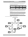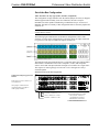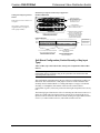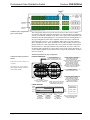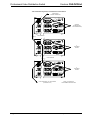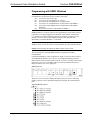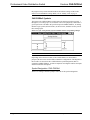
1
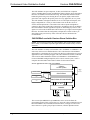
Crestron CNX-PVID8x3
Video Distribution Switch
Operations Guide
This document was prepared and written by the Technical Documentation department at:
Crestron Electronics, Inc.
15 Volvo Drive
Rockleigh, NJ 07647
1-888-CRESTRON
All brand names, product names, and trademarks are the property of their respective owners.
©2005 Crestron Electronics, Inc.
Crestron CNX-PVID8x3
Professional Video Distribution Switch
Contents
Professional Video Distribution Switch: CNX-PVID8x3
1
Introduction ............................................................................................................................... 1
Features and Functions ................................................................................................ 1
Specifications .............................................................................................................. 3
Physical Description.................................................................................................... 4
Industry Compliance ................................................................................................... 8
Setup .......................................................................................................................................... 8
Network Wiring........................................................................................................... 8
Identity Code ............................................................................................................... 9
Cabling and Jumpers ................................................................................................. 12
Rack Mounting .......................................................................................................... 13
Stacking..................................................................................................................... 14
Hardware Hookup ..................................................................................................... 15
Hardware Configurations .......................................................................................... 15
Signal Distribution to More than Eight Rooms ......................................................... 21
Programming Software ............................................................................................................ 23
Earliest Version Software Requirements for the PC ................................................. 23
Programming with the Crestron SystemBuilder........................................................ 23
Programming with SIMPL Windows ........................................................................ 24
Uploading and Upgrading........................................................................................................ 33
Communication Settings ........................................................................................... 34
Uploading a SIMPL Windows Program.................................................................... 36
Firmware Upgrade..................................................................................................... 38
Problem Solving ...................................................................................................................... 39
Troubleshooting......................................................................................................... 39
Further Inquiries ........................................................................................................ 40
Future Updates .......................................................................................................... 40
Return and Warranty Policies .................................................................................................. 41
Merchandise Returns / Repair Service ...................................................................... 41
CRESTRON Limited Warranty................................................................................. 41
Operations Guide - DOC. 8159A
Contents • i
Crestron CNX-PVID8x3
Professional Video Distribution Switch
Professional Video Distribution
Switch: CNX-PVID8x3
Introduction
Features and Functions
The Crestron® Professional Video Distribution Switch, CNX-PVID8x3, is a CAT5
video distribution system that is capable of delivering video from a large number of
separate video sources like DVD players, DSS receivers, tuners, VCRs, and cameras
into a multitude of separate rooms or areas. The exact number of input sources and
output destinations depend on how the unit is to be used in a system: whether or not
it is connected to a Crestron Room Solution Box (CNXRMC or CNXRMCLV).
Its unique design and phenomenal flexibility remove design and installation
constraints from residential systems integration. This unit can provide professional
quality far above the level of consumer-grade equipment for sophisticated home
theaters, kitchens, bedrooms, offices, and outdoor areas. Fully integrated with the
Crestron control system network (Cresnet®) as a network device, the CNX-PVID8x3
is a key component in the Crestron Home® complete solution for distributing video
and control throughout the home.
Functional Summary
•
•
•
•
•
•
•
•
Operations Guide - DOC. 8159A
Accepts NTSC/PAL composite, component, and S-video sources,
including HDTV
Distributes 16, 24, or 32 separate video sources to as many as 8 separate
rooms via CAT5
Three levels of video matrix boards; each with 16 RCA inputs and 8
RCA outputs
Each input includes two RCA connectors wired in parallel; one for video
input, one for termination or loop-through
Each input has built-in video sync sensor to report power/activity status
of source device
RCA output jacks provide single-ended (local mode) video
Eight RJ-45 connectors provide differential (CAT5 mode) video to up to
eight rooms
Internal jumpers and programming enable extensive input/output
configuration flexibility
Professional Video Distribution Switch: CNX-PVID8x3 • 1
Professional Video Distribution Switch
Crestron CNX-PVID8x3
The CNX-PVID8x3 accepts component, S-video, and NTSC/PAL composite
sources, including HDTV signals, and distributes them to display devices throughout
the home via standard CAT5 structured wiring. This distribution method ensures a
balanced signal for long runs, allowing the user to equalize, adjust, and boost the
gain of the video signal for the perfect picture for every application, in every room.
The CNX-PVID8x3 is designed with three levels of video inputs and outputs, each
highly configurable for a variety of video formats. Each of the three levels of
switcher boards implements a video matrix with 16 RCA inputs and eight RCA
outputs for direct single ended video connection to local display devices. In addition,
the CNX-PVID8x3 contains eight RJ-45 outputs for distributing any of these video
signals via CAT5 mode for differential video/control to up to eight rooms throughout
the house. No matter what the configuration, all inputs have a built-in video sync
sensor that reports power/activity status of all source devices attached to the
CNX-PVID8x3.
CNX-PVID8x3 used with Crestron Room Solution Box
NOTE: Systems that incorporate the CNX-PVID8x3 and Crestron Room Solution
Boxes satisfy a vast number of possible applications that could be used by Crestron
customers.
The CNX-PVID8x3 is ideally used in tandem with a CNXRMC or CNXRMCLV in
each room, which receives and decodes the CAT5 video from the CNX-PVID8x3
and supplies it to the display devices in the room. Refer to an illustration of a general
application scenario after this paragraph. This video distribution solution, combined
with Crestron's audio distribution switches (CNX-PAD8A or CNX-BIPAD8), a
Crestron CNAMPX intelligent amplifier, and a 2-Series control system, creates a
complete networked audio/video/control solution for the connected home.
General Application Scenario of the CNX-PVID8x3
2-Series
Control System
SECURITY CAMERA
CRESNET
TO
CNXRMC
OR
CNXRMCLV
COMPOSITE VIDEO
CNX-PVID8x3
COMPONENT VIDEO
VIDEO
(CAT 5)
DVD
AUDIO
VCR
S-VIDEO
CNX-PAD8A OR CNX-BIPAD8
AUDIO
L1
R1
L8
R8
CNAMPX
L1
R1
ROOM SPEAKERS
L8
R8
ROOM SPEAKERS
The Crestron SystemBuilder™ (SystemBuilder) can be used to facilitate the
programming portion of this system. However, due to the wiring constraints between
the CNX-PVID8x3 and Crestron Room Solution Boxes, each type of video source
must connect to a specific group of input connectors, which is dependent on the
2 • Professional Video Distribution Switch: CNX-PVID8x3
Operations Guide - DOC. 8159A
Crestron CNX-PVID8x3
Professional Video Distribution Switch
hardware configuration chosen. Refer to "Hardware Configurations" on page 15 for
specific connection details.
CNX-PVID8x3 used without Crestron Room Solution Box
In this system, the CNX-PVID8x3 has an incredible amount of flexibility with
respect to making connections to all three types of video sources. For example, it is
possible to have a composite source connected to INPUT 1, level 1 and an S-video
source connected to INPUT 1, levels 2 and 3, simultaneously. However, the Crestron
SystemBuilder cannot be used for the programming portion of this kind of system.
All programming is done entirely in SIMPL Windows. Refer to "Programming with
SIMPL Windows" on page 24 for guidance with respect to SIMPL Windows.
Specifications
The following table provides a summary of specifications for the CNX-PVID8x3.
Specifications of the CNX-PVID8x3
SPECIFICATION
Cresnet Power Usage
DETAILS
36 Watts (1.25 Amp @ 24 VDC)
Default Net ID
41
Control System Update Files
1, 2, 3
2-Series Control System
Version 2.004.CUZ or later
CNMSX-AV/PRO
Version 5.14.02X.UPZ or later
CNRACKX/-DP
Version 5.14.02W.UPZ or later
CEN/CN-TVAV
Version 5.12.63V.UPZ or later
Version 4.02.4S.UPZ or later
ST-CP
CNX-PVID8x3 Firmware
4
PVID_16.vx.xxx.upg or later
PVID_16.s19 or later
Rack space required
3U high; 1U wide
Video bandwidth
100 MHz
Crosstalk
> -60 dB
Environmental temperature range
41° to 104°F (5° to 40°C)
Humidity
10% to 90% RH (non-condensing)
Dimensions
(with feet)
Height:
5.31 in (13.49 cm)
Width:
17.16 in (43.59 cm)
Depth:
8.45 in (21.47 cm)
(without feet)
(without mounting ears)
5.21 in (13.24 cm)
Weight
8.6 lb (3.87 kg)
1.
The latest versions can be obtained from the Crestron website. Refer to NOTE after last footnote.
2.
Crestron 2-Series control systems include the AV2 and PRO2. Consult the latest Crestron Product
Catalog for a complete list of 2-Series control systems.
3.
Filenames for CNX and ST-CP update files have a UPZ extension. Files on the website may be .zip
or self-extracting .exe files containing the .cuz or .upz file. All can be obtained from the Downloads
section of the Crestron website. To avoid program problems, make sure you are using the update file
with the correct suffix letter (e.g., S, V, W, X)
4.
In DETAILS, vx.xxx.x represents a version number.
NOTE: Crestron software and any files on the website are for Authorized Crestron
dealers and Crestron Authorized Independent Programmers (CAIP) only. New users
may be required to register to obtain access to certain areas of the site (including the
FTP site).
Operations Guide - DOC. 8159A
Professional Video Distribution Switch: CNX-PVID8x3 • 3
Professional Video Distribution Switch
Crestron CNX-PVID8x3
Physical Description
The CNX-PVID8x3 is housed in a black enclosure with labeling on the front and
rear panels. LEDs on the front of the unit indicate the unit's status. All connections
are made to the back of the unit. Refer to the following illustrations.
CNX-PVID8x3 Front View
CNX-PVID8x3 Rear View
4 • Professional Video Distribution Switch: CNX-PVID8x3
Operations Guide - DOC. 8159A
Crestron CNX-PVID8x3
Professional Video Distribution Switch
CNX-PVID8x3 Physical Views
Rear View
17.16 in
(43.59 cm)
Top View
8.45 in
(21.47 cm)
Front View
19.00 in
(48.26 cm)
PWR
5.31 in
(13.49 cm)
NET
5.21 in
(13.24 cm)
CRESTRON
CNX-PVID8X3
Two mounting ears are provided for rack mounting; four square rubber feet are
provided to be attached to the base of the unit for stability and to prevent slippage in
tabletop mounting or stacking configurations.
CNX-PVID8x3 Ports
A number of ports are provided on the back of the CNX-PVID8x3. Refer to the
illustration and descriptions below.
CNX-PVID8x3 Ports
INPUT 1 – 16 (Levels 1 – 3)
There are three levels of 16 inputs, each input has two RCA jacks connected in
parallel (one for video input, one for termination or loop-through), which are used to
Operations Guide - DOC. 8159A
Professional Video Distribution Switch: CNX-PVID8x3 • 5
Professional Video Distribution Switch
Crestron CNX-PVID8x3
connect independent video sources to the CNX-PVID8x3. Each connector is
supplied with RCA terminators (75 ohm). The terminators should remain attached
unless the INPUT connectors of multiple units are connected (loop-through). Refer
to "Signal Distribution to More than Eight Rooms" on page 21 for a description and
illustration about loop-through. The last unit in the loop must have terminators
installed.
All video inputs have a video sensor so that the power status of all components can
be reported. Only inputs with sync can be reliably detected (composite or
luminance).
OUTPUT (RCA Connectors)
There are three levels of eight RCA jacks (24 total) for single ended (local mode)
video.
NOTE: The information on the OUTPUT RCA connectors and OUTPUT RJ-45
connectors are identical; they are not independently controllable.
OUTPUT (RJ-45 Connectors)
There are eight RJ-45 connectors for differential video (CAT5 mode). The outputs
are grouped into three pairs and correspond to the INPUT levels as shown in the
table after this paragraph. Use a standard CAT5 cable.
Pairing of RJ-45 OUTPUT Connector Pins with respect to the INPUT Levels
RJ-45 Pinout
PAIRED PIN #
ASSOCIATED INPUT LEVEL
1* and 2
3 and 6
4 and 5
7 and 8
1
2
3
not connected
Pin 1
JACK, REAR VIEW
(TAB POSITION DOWN)
* While facing the rear panel of the unit, pin 1 is located at the left side of the port.
NOTE: For additional information on video connections over CAT5, refer to the
latest version of the Crestron CAT5 Wiring Reference Guide (Doc. 6137) which is
available from the Crestron website (http://www.crestron.com/manuals).
NET
This 4-pin terminal block connector is used to connect the CNX-PVID8x3 to the
Cresnet system. Refer to "Network Wiring" on page 8 for details.
CNX-PVID8x3 Indicators
There are 29 LED indicators located on the front panel of the CNX-PVID8x3, and
one on the back panel. Refer to the following illustration and descriptions.
6 • Professional Video Distribution Switch: CNX-PVID8x3
Operations Guide - DOC. 8159A
Crestron CNX-PVID8x3
Professional Video Distribution Switch
CNX-PVID8x3 Indicators
P R O F E S S I O N A L
V I D E O
D I S T R I B U T I O N
S W I T C H
O UT PUT
PWR
1
NET
2
3
4
5
6
7
8
3
A C T IV E V I D E O
2
S E L E C T
IN P U T
1
1
2
3
4
5
6
7
8
9
10
11
12
13
14
15
16
CNX-PVID8X3
CRESTRON
PWR (Power)
This LED illuminates when 24 volts DC from the network is supplied to the
CNX-PVID8x3.
NET
This LED illuminates when communication between the Cresnet system and the
CNX-PVID8x3 is established (unit is polled on the network). Illumination indicates
that the SIMPL Windows program currently loaded has a network device defined at
the same Net ID as the CNX-PVID8x3.
SELECT 1 - 3
These LEDs illuminate when a switcher board (levels 1 through 3) is selected.
Boards can be locally selected with the SELECT pushbutton. Refer to "SELECT
Pushbutton" on this page.
OUTPUT 1 - 8
These eight LEDs illuminate to indicate that a video source is routed via the
respective port to the corresponding room.
ACTIVE VIDEO INPUT
These 16 video sync indicators illuminate to signify active inputs on the selected
board (level).
NOTE: Only composite video and the "Y" S-video/component signal are reliably
detected. If connections to the INPUT connectors are made as recommended by
Crestron in "Hardware Configurations" on page 15, simply use level 1 for detection
of the sync signals.
SETUP LED and Pushbutton
The rear panel SETUP pushbutton and its associated red LED are used for setup of
the unit’s network ID during the initial configuration of a Cresnet system or when
the device is being added/replaced. Refer to “Identity Code” on page 9 for detailed
information.
SELECT Pushbutton
The front panel SELECT pushbutton allows for local selection of the boards (levels 1
through 3). Three indicators are used as feedback.
Operations Guide - DOC. 8159A
Professional Video Distribution Switch: CNX-PVID8x3 • 7
Professional Video Distribution Switch
Crestron CNX-PVID8x3
Industry Compliance
As of the date of manufacture, the CNX-PVID8x3 has been tested and found to
comply with specifications for CE marking and standards per EMC and
Radiocommunications Compliance Labelling.
NOTE: This device complies with part 15 of the FCC rules. Operation is subject to
the following two conditions: (1) these devices may not cause harmful interference,
and (2) these devices must accept any interference received, including interference
that may cause undesired operation.
Setup
Network Wiring
CAUTION: In order to ensure optimum performance over the full range of your
installation topology, Crestron Certified Wire, and only Crestron Certified Wire,
should be used. Failure to do so may incur additional charges if support is required to
identify performance deficiencies as a result of using improper wire.
CAUTION: Use only Crestron power supplies for Crestron equipment. Failure to
do so could cause equipment damage or void the Crestron warranty.
CAUTION: Provide sufficient power to the system. Insufficient power can lead to
unpredictable results or damage to the equipment. Please use the Crestron Power
Calculator to help calculate how much power is needed for the system
(http://www.crestron.com/calculators).
NOTE: When installing network wiring, refer to the latest revision of the wiring
diagram(s) appropriate for your specific system configuration, available from the
Crestron website.
When calculating the wire gauge for a particular Cresnet run, the length of the run
and the Cresnet power usage of each network unit to be connected must be taken into
consideration. If Cresnet units are to be daisy-chained on the run, the Cresnet power
usage of each unit to be daisy-chained must be added together to determine the
Cresnet power usage of the entire chain. If the unit is a home-run from a Crestron
system power supply network port, the Cresnet power usage of that unit is the
Cresnet power usage of the entire run. The length of the run in feet and the Cresnet
power usage of the run should be used in the following resistance equation to
calculate the value on the right side of the equation.
Resistance Equation
40,000
R< LxP
Where: R = Resistance (refer to the following table).
L = Length of run (or chain) in feet.
P = Cresnet power usage of entire run (or chain).
The required wire gauge should be chosen such that the resistance value is less than
the value calculated in the resistance equation. Refer to the table after this paragraph.
8 • Professional Video Distribution Switch: CNX-PVID8x3
Operations Guide - DOC. 8159A
Crestron CNX-PVID8x3
Professional Video Distribution Switch
Wire Gauge Values
RESISTANCE
WIRE GAUGE
4
16
6
18
10
20
15
22
13
Doubled CAT5
8.7
Tripled CAT5
NOTE: All network wiring must consist of two twisted-pairs. One twisted pair is
the +24V conductor and the GND conductor and the other twisted pair is the Y
conductor and the Z conductor.
NOTE: When daisy chaining network units, always twist the ends of the incoming
wire and outgoing wire that share a pin on the network connector. After twisting the
ends, tin the twisted connection with solder. Apply solder only to the ends of the
twisted wires. Avoid tinning too far up or the tinned end becomes brittle and breaks.
After tinning the twisted ends, insert the tinned connection into the network
connector and tighten the retaining screw. Repeat the procedure for the other three
network conductors.
Identity Code
Every equipment and user interface within the network requires a unique identity
code (Net ID). These codes are two-digit hexadecimal numbers from 03 to FE. The
Net ID of the unit must match an ID code specified in the SIMPL Windows program.
Refer to “Setting the Net ID in Device Settings” on page 25 for details of the SIMPL
Windows procedure.
The Net ID of each CNX-PVID8x3 has been factory set to 41. The Net IDs of
multiple CNXPVID8x3s in the same system must be unique. Net IDs are changed
from a personal computer (PC) via the Crestron Viewport.
NOTE: For detailed information on establishing communication between the PC and
control system, refer to “Communication Settings” on page 34. If communication
cannot be established, refer to the “Troubleshooting Communications” section in the
latest version of the 2-Series Control System Reference Guide (Doc. 6256) or the
respective Operations Guide for the control system.
There are two different methods—Method A or Method B—for setting the
CNX-PVID8x3 Net IDs:
Method A (Cresnet address-settable ID), described on the next page, applies to
CNX-PVID8x3s in a Cresnet system with a 2-Series control system upgrade file
(CUZ) version prior to 3.008, but can be used with later versions of firmware and
requires that a single unit be the only network device connected to the control
system.
Method B (Touch Settable IDs), which begins on the next page, applies to
CNX-PVID8x3s in a Cresnet system with 2-Series control system upgrade file
(CUZ) version 3.029 or later. These upgrades enable Touch Settable ID (TSID)
functionality, which makes it possible for the control system to recognize a network
device via its serial number, which is stored in the device’s memory. This method
does not require that any devices be disconnected from the network; Net IDs may be
Operations Guide - DOC. 8159A
Professional Video Distribution Switch: CNX-PVID8x3 • 9
Professional Video Distribution Switch
Crestron CNX-PVID8x3
set with the entire Cresnet system intact. This method requires the use of the
Crestron Viewport version 3.35 or later.
Use the appropriate method to set the CNX-PVID8x3 Net ID.
Method A (Cresnet address-settable ID)
1.
Ensure that the CNX-PVID8x3 is the only device connected to the control
system.
2.
Open the Crestron Viewport.
3.
From the Viewport menu, select Functions | Set Network ID. The software
checks the baud rate and then opens the "Set Network ID" window.
4.
In the "Set Network ID" window, select the CNX-PVID8x3 from the
Current Network Devices text window.
5.
Select the new Net ID for the CNX-PVID8x3 from the Choose the new
network ID for the selected device (Hex): text box.
6.
Click Set ID to initiate the change. This will display the "ID command has
been sent" window.
7.
In the "Command Complete" window, click OK.
8.
In the Current Network Devices text window, verify the new Net ID code.
9.
In the "Set Network ID" window, click Close.
NOTE: The new Net ID code may also be verified by selecting Diagnostic | Report
Network Devices in the Viewport (alternately, select F4).
10. Repeat this procedure for each CNX-PVID8x3 to be added to the system.
Method B (Touch Settable IDs)
Before using this method, you should have a list of all current network devices and
their Net IDs, to avoid assigning duplicate IDs.
Set Net ID by TSID
These procedures are for TSID-enabled network devices during the initial
configuration of a Cresnet system or when such devices are being added/replaced.
1.
Ensure that all CNX-PVID8x3s are connected to the control system.
2.
Open the Crestron Viewport version 3.35 or later.
3.
From the Viewport menu, select Functions | Assign Cresnet ID by Serial
Number. The “Set Net ID by TSID” window appears. The window is first
displayed with the data fields empty. (Refer to the following figure.)
10 • Professional Video Distribution Switch: CNX-PVID8x3
Operations Guide - DOC. 8159A
Crestron CNX-PVID8x3
Professional Video Distribution Switch
“Set Net ID by TSID” Window
4.
Click on the Search for Touch Settable Devices button. The system
searches the network and lists all TSID-enabled devices found. The list is
similar to the report produced by pressing F4 (Report Network Devices);
the first eight digits of each line constitute the TSID number (hexadecimal
form of the serial number).
5.
As you enter either the serial number or TSID number of the device that
requires a change, the corresponding TSID or serial number automatically
appears in its appropriate field, and the list scrolls to and highlights the
device listing. The listing should show the device’s current Cresnet ID.
6.
Enter the Cresnet ID that the device should be set to and click OK. The
number you enter should appear on the list.
CAUTION: This function does not prevent you from setting duplicate IDs. Be sure
to check current assignments before entering the desired Cresnet ID number.
Serial Number to TSID Conversion
This utility is useful in a case where there are multiple devices of the same type on a
network, you need to locate a particular one, you know the TSID but not the serial
number, and your site installation list is based on device serial numbers. In this (or
the reverse) situation, do the following:
Operations Guide - DOC. 8159A
1.
Open the Crestron Viewport.
2.
From the Viewport menu, select Functions | Serial Number ÅÆ TSID
Conversion Tool. The “Serial Number ÅÆTSID Conversion Tool”
window is displayed. (Refer to the following figure.)
Professional Video Distribution Switch: CNX-PVID8x3 • 11
Professional Video Distribution Switch
Crestron CNX-PVID8x3
“Serial Number to TSID Conversion Tool” Window
3.
Enter the serial number or TSID number as instructed; press the appropriate
button to obtain the corresponding number.
NOTE: Enter serial numbers, including spaces, exactly as they appear on the unit
label. Alpha characters in serial numbers or TSID numbers may be entered in upper
or lower case.
Cabling and Jumpers
Out of the box, the CNX-PVID8x3 provides three 16x8 crosspoint boards that can be
operated independently or in parallel. However, versatility was built into the unit.
Depending on how the three boards are cabled and/or jumpered, the unit can be used
in different hardware configurations. For example, cabling boards 1 and 3
conceptually eliminates level 3 (thus component sources are not allowed with this
configuration) and extends level 1 with 16 composite-only connections. Furthermore,
installation of the cable assembly and removal of jumpers splits level 3 (thus
component sources are restricted to inputs 9 through 16) and extends level 1 with
eight composite-only connections.
NOTE: Possible configurations and their respective applications when the
CNX-PVID8x3 is connected to Crestron Room Solution Boxes are summarized in
"Hardware Configurations" on page 15. Furthermore, cabling and jumper removal
may prove useful in systems where the CNX-PVID8x3 does not connect to a
Crestron Room Solution Box. Refer to "Programming with SIMPL Windows" on
page 24 for details of how each configuration is represented in SIMPL Windows.
If the out-of-the-box configuration is desired, the following procedure, which defines
how to install the cable and remove jumpers, need not be completed. If one of the
other configurations is required, the only tools needed to complete this procedure are
a #2 Phillips screwdriver and a grounding strap (grounded workstation).
CAUTION: The CNX-PVID8x3 contains ESD sensitive devices. Perform the
following procedure while wearing a grounding strap that is properly grounded, or
on a grounded workstation to avoid damaging the unit.
NOTE: This procedure assumes that the CNX-PVID8x3 does not have rack ears
attached and has yet to be connected to the network.
1.
Place the CNX-PVID8x3 right side up on a flat surface.
12 • Professional Video Distribution Switch: CNX-PVID8x3
Operations Guide - DOC. 8159A
Crestron CNX-PVID8x3
Professional Video Distribution Switch
2.
Using a #2 Phillips screwdriver, remove the 16 cover screws from the
top (four screws) and sides (six per side) of the CNX-PVID8x3.
3.
Lift and remove the CNX-PVID8x3 top cover.
4.
Use the supplied cable (15863) to connect board 1 (bottom board) to
board 3 (top board), as shown in the diagram that follows this step.
Location of Cable Connection (Side View of Unit)
USE CABLE FOR CONNECTION
OF LEVEL 1 TO LEVEL 3 ONLY
5.
If the desired application requires removal of the jumpers, remove the
nine jumpers from level 3 (top board) only, as shown in the diagram
after this step. Otherwise, skip this step and step 6.
Location of Jumpers (Top View with Cover Removed)
TO SPLIT LEVEL 3,
REMOVE NINE JUMPERS
(FROM LEVEL 3 ONLY)
JUMPER HOLDER
STORES REMOVED
JUMPERS
NOTE: Eight of the nine jumpers are grouped together. Do not forget to remove the
ninth jumper that is located separately from the other eight.
6.
Store jumpers removed in step 5 on the jumper holder, as shown in the
diagram that precedes this step.
7.
Place the cover over the unit (observe proper orientation with respect to
front and back panels) and secure with 16 cover screws.
8.
Tighten screws to finger-tight, then, using a #2 Phillips screwdriver,
tighten an additional 1/8-turn.
Rack Mounting
WARNING: To prevent bodily injury when mounting or servicing this unit in a
rack, take special precautions to ensure that the rack remains stable. The following
guidelines are provided to ensure user safety.
Operations Guide - DOC. 8159A
Professional Video Distribution Switch: CNX-PVID8x3 • 13
Professional Video Distribution Switch
Crestron CNX-PVID8x3
•
The unit should be mounted at the bottom of the rack if it is the only
unit in the rack.
•
When mounting this unit in a partially filled rack, load the rack from
the bottom to the top with the heaviest component at the bottom of the
rack.
•
If the rack is provided with stabilizing devices, install the stabilizers
before mounting or servicing the units in the rack.
NOTE: If rack mounting is not required, rubber feet are provided for tabletop
mounting or stacking. Apply the feet near the corner edges on the underside of the
unit. Refer to "Stacking" on page 14 for details.
NOTE: Reliable grounding of rack-mounted equipment should be maintained.
Particular attention should be given to supply connections other than direct
connections to the branch circuit (e.g., use of power strips).
Two "ears" are provided with the CNX-PVID8x3 so that the unit can be rack
mounted. These ears must be installed prior to mounting. Complete the procedure
below to attach ears to the CNX-PVID8x3. The only tool required for this procedure
is a #2 Phillips screwdriver.
1.
Position a rack ear so that its drilled holes align with the four vacant
holes located on one side of the CNX-PVID8x3.
2.
Use four screws (supplied, #6-32, 3/8"L) to secure the ear to the
CNX-PVID8x3, as shown in the following diagram.
Ear Attachment for Rack Mounting (Side View of Unit)
FASTEN EACH EAR
WITH FOUR
SCREWS (SUPPLIED)
3.
Tighten screws to finger-tight, then, using a #2 Phillips screwdriver,
tighten an additional 1/8-turn.
4.
Repeat procedure (steps 1 and 2) to attach ear to the other side.
5.
If the rear panel of the CNX-PVID8x3 is accessible when mounted in
the rack, install the CNX-PVID8x3. If the rear panel is NOT accessible,
perform the hookup procedure before rack installation.
Stacking
Four "feet" are provided with the CNX-PVID8x3 so that if the unit is not rack
mounted, the rubber feet can provide stability when placed on a flat surface or
stacked. These feet should be attached prior to the hookup procedure. Refer to the
following illustration for placement of the feet.
14 • Professional Video Distribution Switch: CNX-PVID8x3
Operations Guide - DOC. 8159A
Crestron CNX-PVID8x3
Professional Video Distribution Switch
Feet Location (Bottom View of Unit)
ATTACH FEET
NEAR CORNERS
OF THE UNIT
Hardware Hookup
Refer to the hookup diagram after this paragraph. Other than making the power
connection last, complete the connections in any order.
NOTE: For specific details regarding input connections, refer to "Hardware
Configurations" on page 15 if the CNX-PVID8x3 connects to Crestron Room
Solution Boxes within the system.
NOTE: Refer to "Network Wiring" on page 8 when making connections to the port
labeled NET.
Hookup Connections for the CNX-PVID8x3
INPUT:
CRESNET:
FROM VIDEO SOURCES
TO CONTROL
SYSTEM AND
OTHER CRESNET
DEVICES
(ACCEPTS COMPONENT,
S-VIDEO, NTSC/PAL COMPOSITE)
OUTPUT:
OUTPUT:
SINGLE ENDED
(LOCAL) VIDEO TO
MONITOR OR
DISPLAY
DIFFERENTIAL
VIDEO TO ROOM
SOLUTION BOX
Hardware Configurations
NOTE: The hardware configurations described in the following sections only apply
to systems where the CNX-PVID8x3 connects to Crestron Room Solution Boxes.
The Crestron SystemBuilder can generate a program that fits into one of these
configurations.
The CNX-PVID8x3 is constructed with three crosspoint boards; each implements a
16x8x1 matrix. The physical boards are labeled on the back of the unit as "levels" 1,
2, and 3 from bottom to top. Component sources connect to levels 1 through 3 per
input (connect Y to level 1, Pb to level 2, and Pr to level 3). S-video sources use
levels 1 and 2 per input (connect Y to level 1 and C to level 2). Composite sources
should connect to level 1 only (including level 3 extensions of level 1when boards 1
Operations Guide - DOC. 8159A
Professional Video Distribution Switch: CNX-PVID8x3 • 15
Professional Video Distribution Switch
Crestron CNX-PVID8x3
and 3 are connected via the cable assembly). Refer to the table after this paragraph
for a tabulation of the relationship between input levels and video formats.
Relationship of Video Formats to Input Levels
LEVEL \ VIDEO FORMAT
COMPONENT
(connects to
three levels)
S-VIDEO
(connects to
two levels)
COMPOSITE
(connects to
one level*)
Pr
Pb
Y
not connected
C
Y
not connected*
not connected
COMP
3
2
1
* Composite sources can physically connect to level 3 when boards 1 & 3 are connected via the cable assembly.
Depending on how the internal boards are cabled/jumpered, the unit can be used in
different configurations (each is discussed in the following subsections). Refer to the
flowchart below to determine which configuration to use (based on the source types
in the system).
NOTE: Crestron recommends the out-of-the-box configuration, because it allows
for the distribution of a large number of sources with the greatest flexibility and there
is no need to open the unit. The other configurations permit a greater number of
sources, but are not as flexible. The other configurations also require cabling of
boards and possibly the removal of jumpers.
Flowchart: Determine the Configuration
Determine the configuration based
on the sources in the system.
Are there more
than 16 sources in
the system?
No
Use the out-ofthe-box
configuration.
Yes
Consider adding
another
CNX-PVID8x3
to the system.
No
Are there
eight or fewer
component
sources in the
system?
Yes
Are there
component
sources
in the
system?
No
Is
the number
of component and
S-video sources in
the system
less than
16?
No
Yes
Are there
eight or fewer
S-video
sources in the
system?
Are there 16 or
fewer composite
sources in the
system?
Yes
Yes
Are there
eight or fewer
composite
sources in the
system?
Are there 16 or
fewer S-video
sources in the
system?
No
Consider adding
another
CNX-PVID8x3
to the system.
Yes
Yes
Consider adding
another
CNX-PVID8x3
to the system.
No
Yes
Use the limited
quantity of anytype configuration.
No
Is
the number
of S-video and
composite sources in
the system
less than
32?
No
Consider adding
another
CNX-PVID8x3
to the system.
Yes
Use the
composite/S-video
only configuration.
No
Consider adding
another
CNX-PVID8x3
to the system.
No
Is
the number
of component, Svideo, and composite
sources in the system
less than 24?
Yes
16 • Professional Video Distribution Switch: CNX-PVID8x3
Operations Guide - DOC. 8159A
Crestron CNX-PVID8x3
Professional Video Distribution Switch
Out-of-the-Box Configuration
AKA: 16 Sources of Any Type (Video, S-Video, Component)
This configuration is aptly named because the internal jumpers are intact, as shipped,
and the supplied cable assembly is not used. Therefore, the unit is ready for
immediate use and is capable of distributing a combination of up to 16 sources of
any type. The built-in versatility of this configuration makes it the most popular and
easiest to use.
NOTE: Installers only need to consider another configuration if the system consists
of more than 16 sources.
The following figure illustrates the out-of-the-box configuration—three 16X8
switchers in a stack. In this configuration as well as the others, the inputs connected
to a given level can only be routed to the outputs for that level.
The illustration after this paragraph depicts a system that utilizes the CNX-PVID8x3
and contains a combination of 16 or fewer composite, S-video, and component
sources. Notice that each input (labeled 1 through 16) can connect to a single source.
The sequence of video signal type is irrelevant. Levels 1 through 3 are always
switched together.
Illustration of Out-of-the-Box Configuration
Cabling and Jumpering of Internal
Boards:
Cable between level 1 and level 3
is not attached.
Nine jumpers remain in their
original location (no jumpers
on the jumper holder).
1
2
3
4
5
6
7
INPUT
8
9
10
11
12
13
14
15
16
G
1
OUTPUT
2
3
NET
4
SETUP
24 Y
Z
G
3
5
6
7
8
1
2
3
4
1
2
5
6
OUTPUT
3
4
7
8
2
5
6
7
8
1
2
3
4
5
6
7
8
1
C RES T RO N
E L E C T R O N IC S
I N C . R O C K L E IG H , N . J . 0 7 6 4 7
USA
NOTES:
COMPONENT - CONNECTS TO 1, 2, & 3.
S-VIDEO - CONNECTS TO 1 & 2 ONLY.
COMPOSITE - CONNECTS TO 1 ONLY.
EACH SOURCE CONNECTS TO A SINGLE
INPUT (LABELED 1 THROUGH 16).
THE SEQUENCE OF SOURCES IS
INDEPENDENT OF VIDEO FORMAT.
MAXIMUM NUMBER OF SOURCES ALLOWED
WITH THIS CONFIGURATION IS 16.
Operations Guide - DOC. 8159A
Professional Video Distribution Switch: CNX-PVID8x3 • 17
Professional Video Distribution Switch
Crestron CNX-PVID8x3
Cabled Configuration (Composite/S-Video Only)
AKA: 16 Video & Up to 16 S-Video or Video Sources
NOTE: Dealing with a system that contains more than 16 sources? This
configuration may be preferred as long as the system does not contain component
video.
To achieve this configuration, the unit must be opened and the cable assembly
attached. Refer to "Cabling and Jumpers" on page 12 for details. The internal
jumpers remain intact.
The following figure shows the effect of connecting the cable between the level 1
and level 3 boards. The level 3 inputs become an extension of the level 1 board,
resulting in a logical 32X8 switcher on level 1 and a 16X8 switcher on level 2; the
level 3 outputs are not used.
Conditions of this configuration;
please read carefully!
This configuration allows for the greatest number of sources, 32. However, those
sources can only be composite (up to 32, when there is no S-video) and S-video (up
to 16, maximum). The illustration after this paragraph provides a visual depiction of
a system that utilizes the CNX-PVID8x3 in the composite/S-video only
configuration. Notice that S-video sources can only be connected to input 1 through
16 (connect Y to level 1 and C to level 2). Installation of the cable assembly
conceptually eliminates level 3 (thus component sources are not allowed with this
configuration) and extends level 1 with 16 composite-only connections. Of course, if
there are fewer than 16 S-video sources in the system, the number of composite
sources can increase as long as the total number of composite and S-video sources
does not exceed 32.
NOTE: The composite sources connected to level 3 are switchable to the output on
level 1.
18 • Professional Video Distribution Switch: CNX-PVID8x3
Operations Guide - DOC. 8159A
Crestron CNX-PVID8x3
Professional Video Distribution Switch
Illustration of Composite/S-Video Only Configuration
Cabling and Jumpering Internal
Boards:
PHYSICAL CONNECTIONS:
1
Cable between level 1 and level 3
is in place.
2
3
4
5
6
7
INPUT
8
9
10
11
12
3
13
14
15
16
COMPOSITE SOURCES*:
PHYSICALLY CONNECT TO LEVEL 3
(INPUTS 1 THROUGH 16),
BUT ARE LOGICALLY AN
EXTENSION OF LEVEL 1.
2
Nine jumpers remain in their
original location (no jumpers
on the jumper holder).
S-VIDEO SOURCES:
PHYSICALLY CONNECT TO LEVELS 1 & 2
(INPUTS 1 THROUGH 16) ONLY.
1
C R E S T R O N E L E C T R O N IC S I N C . R O C K L E I G H , N . J . 0 7 6 4 7 U S A
REFER TO THE LOGICAL DEPICTION
(SHOWN BELOW) OF THE PHYSICAL
CONNECTIONS (SHOWN ABOVE).
LOGICAL DEPICTION:
INPUTS
1 2 3 4 5 6 7 8 9 10 11 12 13 14 15 16
*COMPOSITE SOURCES CAN CONNECT
TO LEVEL 1 (WHEN THERE ARE
FEWER THAN 16 S-VIDEO SOURCES).
HOWEVER, THE TOTAL NUMBER
OF COMPOSITE AND S-VIDEO
SOURCES CANNOT EXCEED 32.
SWITCHABLE TO:
17 18 19 20 21 22 23 24 25 26 27 28 29 30 31 32
LEVEL 2
OUTPUT LEVEL 2
LEVEL 1
LEVEL 3
UP TO 16 S-VIDEO SOURCES ARE PERMITTED
NOTE: WHEN THERE ARE FEWER THAN
16 S-VIDEO SOURCES, COMPOSITE
SOURCES CAN CONNECT TO LEVEL 1.
OUTPUT LEVEL 1
16 (OR MORE) COMPOSITE SOURCES*
ARE PERMITTED.
NOTE: THE LABELING OF INPUTS 17
THROUGH 32 BECOMES USEFUL
WHEN PROGRAMMING.
Split Board Configuration (Limited Quantity of Any Input
Type)
AKA: 8 Video, Up to 8 S-Video/Video, and Up to 8 Component/S-Video/Video
Sources
NOTE: Dealing with a system that contains more than 16 sources? This
configuration may be preferred as long as the system does not contain more than
eight component video sources.
This configuration somewhat mimics the out-of-the-box configuration, but there are
differences. The first difference is that jumpers need to be removed and the cable
assembly must be attached. Refer to "Cabling and Jumpers" on page 12 for details.
Secondly, even though the total number of mixed sources allowed in this
configuration is greater, it does not permit more than eight component sources at any
time.
The following figure illustrates the effect of connecting the cable between the level 1
and level 3 boards and removing the jumpers from the level 3 board. Eight level 3
inputs become an extension of the level 1 board, resulting in a logical 24X8 switcher
on level 1, a 16X8 switcher on level 2; and an 8X8 switcher on level 3.
Operations Guide - DOC. 8159A
Professional Video Distribution Switch: CNX-PVID8x3 • 19
Professional Video Distribution Switch
Conditions of this configuration;
please read carefully!
Crestron CNX-PVID8x3
This configuration allows for up to 24 sources. However, those sources cannot
exceed more than eight component, more than 16 S-video (assuming no component
sources), more than 24 composite (when there is no S-video and no component). The
illustration after this paragraph depicts a system that utilizes the limited quantity of
any-type configuration. Notice that component sources can only be connected to
input 9 through 16 (levels 1, 2, & 3) and that S-video sources can only connect to
input 1 through 8 (levels 1 and 2). Installation of the cable assembly and removal of
jumpers splits level 3 (thus component sources are restricted to inputs 9 through 16)
and extends level 1 with eight composite-only connections. Of course, if there are
fewer than eight component (or eight S-video) sources in the system, the number of
S-video and/or composite sources can increase as long as the total number of sources
does not exceed 24.
Illustration of Limited Any-Type Configuration
Cabling and Jumpering Internal
Boards:
PHYSICAL CONNECTIONS:
Cable between level 1 and level 3
is in place.
Nine jumpers are removed from
their original location and stored
on the jumper holder.
1
2
3
4
5
6
7
*COMPOSITE SOURCES CAN CONNECT TO
LEVEL 1, INPUTS 1 THROUGH 8
(WHEN THERE ARE LESS THAN
EIGHT S-VIDEO SOURCES).
COMPOSITE SOURCES CAN ALSO CONNECT
TO LEVEL 1, INPUTS 9 THROUGH 16
(WHEN THERE ARE LESS THAN
EIGHT COMPONENT SOURCES).
HOWEVER, THE TOTAL NUMBER OF
COMPOSITE, S-VIDEO, AND COMPONENT
SOURCES CANNOT EXCEED 24.
COMPOSITE SOURCES*:
PHYSICALLY CONNECT TO LEVEL 3
(INPUTS 1 THROUGH 8), BUT ARE
LOGICALLY AN EXTENSION OF LEVEL 1.
INPUT
8
9
10
11
12
13
14
15
16
3
COMPONENT SOURCES:
PHYSICALLY CONNECT TO LEVELS 1, 2, & 3
(INPUTS 9 THROUGH 16) ONLY.
2
1
C REST RO N
E L E C T R O N IC S
IN C . R O C K L E IG H , N . J . 0 7 6 4 7
USA
S-VIDEO SOURCES**:
PHYSICALLY CONNECT TO LEVELS
1 & 2 (INPUTS 1 THROUGH 8).
LOGICAL DEPICTION:
INPUTS
**S-VIDEO SOURCES CAN CONNECT TO
LEVELS 1 OR 2, INPUTS 9 THROUGH 16
(WHEN THERE ARE LESS THAN
EIGHT COMPONENT SOURCES).
HOWEVER, THE TOTAL NUMBER OF
S-VIDEO AND COMPONENT
REFER TO THE LOGICAL DEPICTION
SOURCES CANNOT EXCEED 16.
(SHOWN BELOW) OF THE PHYSICAL
CONNECTIONS (SHOWN ABOVE).
1 2 3 4 5 6 7 8 9 10 11 12 13 14 15 16
SWITCHABLE TO:
17 18 19 20 21 22 23 24
OUTPUT LEVEL 3
LEVEL 3
PART
OF
LEVEL 3
LEVEL 2
LEVEL 1
EIGHT (OR
MORE) S-VIDEO
SOURCES**
ARE PERMITTED.
UP TO EIGHT
COMPONENT
SOURCES ARE
PERMITTED.
20 • Professional Video Distribution Switch: CNX-PVID8x3
EIGHT (OR
MORE) COMPOSITE
SOURCES*
ARE PERMITTED.
OUTPUT LEVEL 2
OUTPUT LEVEL 1
NOTE: THE LABELING OF INPUTS 17
THROUGH 24 BECOMES USEFUL
WHEN PROGRAMMING.
Operations Guide - DOC. 8159A
Crestron CNX-PVID8x3
Professional Video Distribution Switch
Configuration Wiring Guidelines
Once a configuration is chosen and any appropriate physical modifications to the
CNX-PVID8x3 have been made, wiring can begin. Refer to the following guidelines.
•
Begin adding component sources at input 16 and work toward input 1 on all
three levels.
•
Add composite sources beginning at input 1. In the out-of-box
configuration, add sources on level 1. For any other configuration, begin on
level 3.
•
S-video is places on levels 1 and 2 on any unused inputs.
•
Wire S-video Y on level 1; C on level 2. Wire component with green on
level 1 (Y), blue on level 2 (Pb), and red on level 3 (Pr). This keeps sync for
all sources on level 1, which greatly simplifies troubleshooting.
•
Remember to leave terminators in place on any unused input on any level.
RCA outputs can be wired using the same guidelines as inputs: component beginning
as output 8 and composite beginning at output 1. When using the CAT5 outputs,
remember that each CAT5 connector represents all three levels of the unit.
Signal Distribution to More than Eight Rooms
Each CNX-PVID8x3 is capable of distributing video to eight rooms, maximum. It is
possible to expand distribution to more rooms, if additional CNX-PVID8x3s are
introduced to the system. Crestron recommends a maximum of four CNX-PVID8x3s
per system. Therefore, video can be distributed to a maximum of 32 rooms. Each
input to the unit has two RCA jacks connected in parallel (per level). Use one of the
jacks for loop-through, as shown in the illustration after this paragraph.
NOTE: The last unit in the loop-through connection must have terminators
installed.
Operations Guide - DOC. 8159A
Professional Video Distribution Switch: CNX-PVID8x3 • 21
Professional Video Distribution Switch
Crestron CNX-PVID8x3
Video Distribution Expansion with Additional CNX-PVID8x3s
VIDEO SIGNAL
SOURCE CONNECTION
1
2
1
OUTPUT
2
3
NET
4
SETUP
24 Y
Z
G
3
5
6
7
8
1
2
3
4
1
2
5
OUTPUT
3
4
6
7
8
SETUP
24 Y
2
5
6
7
8
1
2
3
4
5
6
7
8
8 ROOMS
(EITHER RCA OR
CAT5 CONNECTIONS)
1
C RE ST RO N
E L E C T R O N IC
LOOP-THROUGH
1
2
1
OUTPUT
2
3
NET
4
Z
G
3
5
6
7
8
1
2
3
4
1
2
5
OUTPUT
3
4
6
7
8
SETUP
24 Y
2
5
6
7
8
1
2
3
4
5
6
7
8
8
ADDITIONAL
ROOMS
1
C RE ST RO N
E L E C T R O N IC
LOOP-THROUGH
1
2
1
OUTPUT
2
3
NET
4
Z
G
3
5
6
7
8
1
2
3
4
1
2
5
6
OUTPUT
3
4
7
8
2
5
6
7
8
1
2
3
4
5
6
7
8
8
ADDITIONAL
ROOMS
1
C RE ST RO N
E L E C T R O N IC
LOOP THROUGH UP TO 4 CNX-PVID8x3s
(32 ROOMS TOTAL)
22 • Professional Video Distribution Switch: CNX-PVID8x3
NOTE: LAST UNIT MUST
HAVE TERMINATORS INSTALLED.
Operations Guide - DOC. 8159A
Crestron CNX-PVID8x3
Professional Video Distribution Switch
Programming Software
Have a question or comment about Crestron software?
Answers to frequently asked questions (FAQs) can be viewed in the Online Help
section of the Crestron website. To post a question or view questions you have
submitted to Crestron’s True Blue Support, log in at http://support.crestron.com./
First-time users will need to establish a user account.
You can create a program that allows you to include the CNX-PVID8x3 in a
Crestron control system using the Crestron programming tools Crestron
SystemBuilder™ and SIMPL Windows. These tools are intended for users with
different levels of programming knowledge. The flexibility of each tool is
proportional to the degree of programming expertise (i.e., the more flexible, the more
a programmer needs to know and account for). Of course, one can initiate
programming using the easiest method (SystemBuilder) and use advanced techniques
that are available from SIMPL Windows to customize the job.
Earliest Version Software Requirements for the PC
NOTE: Crestron recommends that you use the latest software to take advantage of
the most recently released features. The latest software is available from the Crestron
website.
The following are recommended software version requirements for the PC:
•
(Optional) SystemBuilder version 2.0 or later. Requires SIMPL Windows and
Crestron Engraver. Requires SystemBuilder templates 1.10 or later.
•
SIMPL Windows version 2.05.22 or later.
Requires SIMPL+ Cross Compiler version 1.1.
•
Crestron Database version 16.4.4 or later. Required by SIMPL Windows.
•
Crestron Engraver version 2.3.3.2 (required if using SystemBuilder).
Programming with the Crestron SystemBuilder
The easiest method of
programming, but does not
offer as much flexibility as
SIMPL Windows.
The Crestron SystemBuilder offers automatic programming for such residential and
commercial applications as audio distribution, home theater, video conferencing, and
lighting. The interface of this tool guides you through a few basic steps for
designating rooms and specifying the control system, touchpanels, devices, and
functionality. The Crestron SystemBuilder then programs the system, including all
touchpanel projects and control system logic.
Crestron SystemBuilder is fully integrated with Crestron's suite of software
development tools, including SIMPL Windows, Crestron VisionTools® Pro-e (VT
Pro-e), Crestron Engraver, Crestron Database, User IR Database, and User Modules
Directory. Crestron SystemBuilder accesses these tools behind the scenes, enabling
you to easily create robust systems.
Operations Guide - DOC. 8159A
Professional Video Distribution Switch: CNX-PVID8x3 • 23
Professional Video Distribution Switch
Crestron CNX-PVID8x3
Programming with SIMPL Windows
NOTE: The following are acceptable file extensions for programs that include a
CNX-PVID8x3, developed for specific control system types:
.smw projectname.smw (source file)
.spz
projectname.spz (compiled file for 2-series)
.bin
projectname.bin (compiled file for CNX generation)
.csz
projectname.csz (compiled file for CNX generation with SIMPL+)
.ush
projectname.ush (compiled file for CNX generation with SIMPL+
header file)
.usp
projectname.usp (source code module for SIMPL+)
SIMPL Windows is Crestron's software for programming Crestron control systems.
It provides a well-designed graphical environment with a number of workspaces
(i.e., windows) in which a programmer can select, configure, program, test, and
monitor a Crestron control system. SIMPL Windows offers drag and drop
functionality in a familiar Windows® environment.
NOTE: The following descriptions assume that the reader has knowledge of SIMPL
Windows. If not, refer to the extensive help information provided with the software.
NOTE: In the following description, the PRO2 control system is used.
This section describes a sample SIMPL Windows program that includes a
CNX-PVID8x3.
Configuration Manager is where programmers “build” a Crestron control system by
selecting hardware from the Device Library. In Configuration Manager, drag the
PRO2 from the Control Systems folder of the Device Library and drop it in the upper
pane of the System Views. The PRO2 with its associated communication ports is
displayed in the System Views upper pane.
PRO2 System View
The System Views lower pane displays the PRO2 system tree (refer to following
graphic). This tree can be expanded to display and configure the communications
ports.
Expanded PRO2 System Tree
24 • Professional Video Distribution Switch: CNX-PVID8x3
Operations Guide - DOC. 8159A
Crestron CNX-PVID8x3
Professional Video Distribution Switch
C2Net Device Slot in Configuration Manager
To incorporate a CNX-PVID8x3 into the system, drag the CNX-PVID8x3 from the
Cresnet Control Modules | Cresnet Video Modules folder of the Device Library and
drop it in System Views. The PRO2 system tree displays the CNX-PVID8x3 in Slot
9, with a default Net ID of 41 as shown in the following illustration.
NOTE: SIMPL Windows provides three separate symbols for the CNX-PVID8x3,
each one intended for a particular system configuration. Select the appropriate one to
be placed in System Views. Refer to “CNX-PVID8x3 Symbols” on page 26 for
details about each symbol.
NOTE: The first CNX-PVID8x3 in a system is preset with a Net ID of 41 when its
symbol is dragged into the upper pane of System Views. Additional units are assigned
different Net ID numbers as they are added.
C2Net Device, Slot 9
Setting the Net ID in Device Settings
Double-click the CNX-PVID8X3 icon to open the “Device Settings” window. This
window displays the CNX-PVID8X3 device information. If necessary, select the Net
ID tab to change the unit’s Net ID, as shown in the following figure.
CNX-PVID8x3- “Device Settings” Window
NOTE: SIMPL Windows automatically changes Net ID values of a device added to a
program if a duplicate device or a device with the same default Net ID already exists in
Operations Guide - DOC. 8159A
Professional Video Distribution Switch: CNX-PVID8x3 • 25
Professional Video Distribution Switch
Crestron CNX-PVID8x3
the program. Always ensure that the hardware and software settings of the Net ID
match. For Net ID hardware setting details, refer to “Identity Code” on page 9.
CNX-PVID8x3 Symbols
The inputs to the CNX-PVID8x3 symbol require the analog equivalent (typically 1
through 16, but could go up to 32) so that the video source physically connected to a
given input can be switched to the specified output. In SIMPL Windows, an Analog
Initialize logic symbol (decimal format), as shown below, should be used to provide
these analog inputs.
Detail View of the Analog Initialize Symbol in SIMPL Windows' Programming Manager
NOTE: The "0d" indicates no source.
Depending on how the three boards of the CNX-PVID8x3 are cabled and/or
jumpered, the unit can be used in different hardware configurations. The diagrams in
the next three sections show three CNX-PVID8x3 symbol designations that are
available in SIMPL Windows. A table accompanies each diagram and lists the inputs
and their functional descriptions.
Symbol Designation: CNX-PVID8x3
There is no cabling of boards or jumpers removed for this symbol designation.
26 • Professional Video Distribution Switch: CNX-PVID8x3
Operations Guide - DOC. 8159A
Crestron CNX-PVID8x3
Professional Video Distribution Switch
Detail View of the CNX-PVID8x3 Symbol in SIMPL Windows' Programming Manager
CNX-PVID8x3 Symbol Input Descriptions
INPUT(S)
Operations Guide - DOC. 8159A
FUNCTION(S)
Src-For-Out-1Level-1 through
Src-For-Out-8Level-1
Provide the analog equivalent (1 through 16) via the
Analog Initialize symbol (decimal format) on this line so
that the video source connected to the given input (on
level 1) can be switched to the specified output on level 1.
Src-For-Out-1Level-2 through
Src-For-Out-8Level-2
Provide the analog equivalent (1 through 16) via the
Analog Initialize symbol (decimal format) on this line so
that the video source connected to the given input (on
level 2) can be switched to the specified output on level 2.
Src-For-Out-1Level-3 through
Src-For-Out-8Level-3
Provide the analog equivalent (1 through 16) via the
Analog Initialize symbol (decimal format) on this line so
that the video source connected to the given input (on
level 3) can be switched to the specified output on level 3.
Professional Video Distribution Switch: CNX-PVID8x3 • 27
Professional Video Distribution Switch
Crestron CNX-PVID8x3
CNX-PVID8x3 Symbol Output Descriptions
OUTPUT(S)
FUNCTION(S)
Sense-in-1-Level-1
through Sense-in16-Level-1
High if a video signal is detected on the specific input (1 –
16) on level 1; otherwise, 0 (zero).
Sense-in-1-Level-2
through Sense-in16-Level-2
High if a video signal is detected on the specific input (1 –
16) on level 2; otherwise, 0 (zero).
Sense-in-1-Level-3
through Sense-in16-Level-3
High if a video signal is detected on the specific input (1 –
16) on level 3; otherwise, 0 (zero).
This symbol designation allows the programmer to attach inputs and outputs to the
CNX-PVID8x3 when it is configured as three independent levels (16 input to eight
outputs). On each level, the 16 inputs can be switched to any of the eight outputs on
the same level.
DEPICTION OF LEVELS ON BACK OF UNIT:
LEVEL 3
16 IN X 8 OUT
LEVEL 2
16 IN X 8 OUT
LEVEL 1
16 IN X 8 OUT
DEPICTION OF SYMBOL IN SIMPL WINDOWS:
VIA THE ANALOG
INITIALIZE SYMBOL
(DECIMAL FORMAT)
ASSIGN THE ANALOG
EQUIVALENT (1 - 16)
OF AN INPUT TO A
SPECIFIC OUTPUT
(1 - 8) ON THE
SAME LEVEL
28 • Professional Video Distribution Switch: CNX-PVID8x3
Src-For-Out-1-Level-1
Src-For-Out-2-Level-1
Src-For-Out-8-Level-1
Operations Guide - DOC. 8159A
Crestron CNX-PVID8x3
Professional Video Distribution Switch
Symbol Designation: CNX-PVID8x3J13
For this symbol designation, level 3 is connected to level 1 with the supplied cable.
This is the equivalent of extending level 1 with 16 additional inputs.
Detail View of the CNX-PVID8x3J13 Symbol in SIMPL Windows' Programming Manager
CNX-PVID8x3J13 Symbol Input Descriptions
INPUT(S)
Operations Guide - DOC. 8159A
FUNCTION(S)
Src-For-Out-1Level-1 through
Src-For-Out-8Level-1
Provide the analog equivalent (1 through 32) via the
Analog Initialize symbol (decimal format) on this line so
that the video source connected to the given input (on
level 1, including the extension from level 3) can be
switched to the specified output on level 1.
Src-For-Out-1Level-2 through
Src-For-Out-8Level-2
Provide the analog equivalent (1 through 16) via the
Analog Initialize symbol (decimal format) on this line so
that the video source connected to the given input (on
level 2) can be switched to the specified output on level 2.
Professional Video Distribution Switch: CNX-PVID8x3 • 29
Professional Video Distribution Switch
Crestron CNX-PVID8x3
CNX-PVID8x3J13 Symbol Output Descriptions
OUTPUT(S)
FUNCTION(S)
Sense-in-1-Level-1
through Sense-in16-Level-1
High if a video signal is detected on the specific input (1 –
16) on level 1 (including extension from level 3);
otherwise, 0 (zero).
Sense-in-1-Level-2
through Sense-in16-Level-2
High if a video signal is detected on the specific input (1 –
16) on level 2; otherwise, 0 (zero).
Sense-in-1-Level-3
through Sense-in16-Level-3
Identical to those output signals on Sense-In-1-Level-1
through Sense-In16-Level-1.
This symbol allows the programmer to attach inputs and outputs to the
CNX-PVID8x3 when it is configured as two levels (one with 32 inputs to eight
outputs and the other with 16 inputs to eight outputs). On level 1, the 32 inputs can
be switched to any of the eight outputs on the same level. Likewise, the 16 inputs on
level 2 can be switched to any of the eight outputs on level 2.
DEPICTION OF LEVELS ON BACK OF UNIT:
LEVEL 2
16IN X 8OUT
LEVEL 1
32IN X 8OUT
DEPICTION OF SYMBOL IN SIMPL WINDOWS:
VIA THE ANALOG INITIALIZE
SYMBOL (DECIMAL FORMAT)
ASSIGN THE ANALOG EQUIVALENT
(1 - 16 FROM LEVEL 1 AND
17 - 32 FROM LEVEL 3) OF
AN INPUT TO A SPECIFIC
OUTPUT (1 - 8) ON LEVEL 1
VIA THE ANALOG INITIALIZE
SYMBOL (DECIMAL FORMAT)
ASSIGN THE ANALOG EQUIVALENT
(1 - 16 FROM LEVEL 2) OF
AN INPUT TO A SPECIFIC
OUTPUT (1 - 8) ON LEVEL 2
30 • Professional Video Distribution Switch: CNX-PVID8x3
Src-For-Out-1-Level-1
Src-For-Out-2-Level-1
Src-For-Out-8-Level-1
Src-For-Out-1-Level-2
Src-For-Out-2-Level-2
Src-For-Out-8-Level-2
Operations Guide - DOC. 8159A
Crestron CNX-PVID8x3
Professional Video Distribution Switch
Symbol Designation: CNX-PVID8x3J13S
For this symbol designation, level 3 is divided in half by removing jumpers.
Furthermore, half of level 3 (inputs 1 through 8) is connected to level 1 with the
supplied cable. This is the equivalent of extending level 1 with eight additional
inputs and still allowing for connections to component video sources.
Detail View of the CNX-PVID8x3J13S Symbol in SIMPL Windows' Programming
Manager
CNX-PVID8x3J13S Symbol Input Descriptions
INPUT(S)
FUNCTION(S)
Src-For-Out-1Level-1 through
Src-For-Out-8Level-1
Provide the analog equivalent (1 through 24) via the
Analog Initialize symbol (decimal format) on this line so
that the video source connected to the given input (on
level 1, including the extension from level 3) can be
switched to the specified output on level 1.
(continued on next page)
Operations Guide - DOC. 8159A
Professional Video Distribution Switch: CNX-PVID8x3 • 31
Professional Video Distribution Switch
Crestron CNX-PVID8x3
CNX-PVID8x3J13S Symbol Input Descriptions (continued)
INPUT(S)
FUNCTION(S)
Src-For-Out-1Level-2 through
Src-For-Out-8Level-2
Provide the analog equivalent (1 through 16) via the
Analog Initialize symbol (decimal format) on this line so
that the video source connected to the given input (on
level 2) can be switched to the specified output on level 2.
Src-For-Out-1Level-3 through
Src-For-Out-8Level-3
Provide the analog equivalent (9 through 16) via the
Analog Initialize symbol (decimal format) on this line so
that the video source connected to the given input (on
half of level 3) can be switched to the specified output on
level 3.
CNX-PVID8x3J13S Symbol Digital Output Descriptions
OUTPUT(S)
FUNCTION(S)
Sense-in-1-Level-1
through Sense-in16-Level-1
High if a video signal is detected on the specific input (1 –
16) on level 1 (including extension from level 3);
otherwise, 0 (zero).
Sense-in-1-Level-2
through Sense-in16-Level-2
High if a video signal is detected on the specific input (1 –
16) on level 2; otherwise, 0 (zero).
Sense-in-1-Level-3
through Sense-in16-Level-3
High if a video signal is detected on the specific input (1 –
16) on half of level 3; otherwise 0 (zero).
This symbol allows the programmer to attach inputs and outputs to the
CNX-PVID8x3 when it is configured as three levels with varying quantities of inputs
(one with 24 inputs to eight outputs, one with 16 inputs to eight outputs, and the
other with eight inputs to eight outputs). On level 1, the 24 inputs can be switched to
any of the eight outputs on the same level. Likewise, the 16 inputs on level 2 can be
switched to any of the eight outputs on level 2 and the eight inputs on level 2 can be
switched to any of the eight outputs on level 3. (Refer to the following figure.)
32 • Professional Video Distribution Switch: CNX-PVID8x3
Operations Guide - DOC. 8159A
Crestron CNX-PVID8x3
Professional Video Distribution Switch
DEPICTION OF LEVELS ON BACK OF UNIT:
LEVEL 3
8 IN X 8 OUT
LEVEL 2
16IN X 8OUT
LEVEL 1
24IN X 8OUT
DEPICTION OF SYMBOL IN SIMPL WINDOWS:
VIA THE ANALOG INITIALIZE
SYMBOL (DECIMAL FORMAT)
ASSIGN THE ANALOG EQUIVALENT
(1 - 16 FROM LEVEL 1 AND
17 - 24 FROM LEVEL 3) OF
AN INPUT TO A SPECIFIC
OUTPUT (1 - 8) ON LEVEL 1
VIA THE ANALOG INITIALIZE
SYMBOL (DECIMAL FORMAT)
ASSIGN THE ANALOG EQUIVALENT
(1 - 16 FROM LEVEL 2) OF
AN INPUT TO A SPECIFIC
OUTPUT (1 - 8) ON LEVEL 2
VIA THE ANALOG INITIALIZE
SYMBOL (DECIMAL FORMAT)
ASSIGN THE ANALOG EQUIVALENT
(1 - 8 FROM LEVEL 3) OF
AN INPUT TO A SPECIFIC
OUTPUT (1 - 8) ON LEVEL 3
Src-For-Out-1-Level-1
Src-For-Out-2-Level-1
Src-For-Out-8-Level-1
Src-For-Out-1-Level-2
Src-For-Out-2-Level-2
Src-For-Out-8-Level-2
Src-For-Out-1-Level-3
Src-For-Out-2-Level-3
Src-For-Out-8-Level-3
Example Program
An example program for the CNX-PVID8x3 is available from the “Example
Program” section of the Crestron website
(http://www.crestron.com/exampleprograms). Search for CNX-PVID8X3 Example
Program (ZIP).
Uploading and Upgrading
NOTE: Crestron recommends that you use the latest software and that each device
contains the latest firmware to take advantage of the most recently released features.
Please check the Crestron website (http://www.crestron.com/updates) for the latest
versions of software and firmware. New users are required to register to obtain
access to this site.
Assuming a PC is properly connected to the entire system, Crestron programming
software allows the programmer to upload programs and projects after their
development to the system and network devices. However, there are times when the
files for the program and projects are compiled and not uploaded. Instead, compiled
files may be distributed from programmers to installers, from Crestron to dealers,
etc. Even firmware upgrades are available from the Crestron website as new features
are developed after product releases. In those instances, one has the option to upload
via the programming software or to upload and upgrade via the Crestron Viewport.
Operations Guide - DOC. 8159A
Professional Video Distribution Switch: CNX-PVID8x3 • 33
Professional Video Distribution Switch
Crestron CNX-PVID8x3
NOTE: The Crestron Viewport utility performs multiple system tasks, primarily via
an RS-232 or TCP/IP connection between the control system and a PC. It is used to
observe system processes, upload new operating systems and firmware, change
system and network parameters, and communicate with network device consoles and
touchpanels, among many other tasks. Viewport can also function as a terminal
emulator for generic file transfer. All of these functions are accessed through the
commands and options in the Viewport menus. Therefore, for its effectiveness as a
support and diagnostic tool, the Crestron Viewport may be preferred over
development tools when uploading programs and projects.
The following sections define how one would upload a SIMPL Windows program or
upgrade the firmware of the CNX-PVID8x3. However, before attempting to upgrade,
it is necessary to establish communications.
Communication Settings
NOTE: For laptops and other PCs without a built-in RS-232 port, Crestron
recommends the use of PCMCIA cards, rather than USB-to-serial adapters. If a
USB-to-serial adapter must be used, Crestron has tested the following devices with
good results:
Belkin (large model) F5U103
I/O Gear GUC232A (discontinued)
Keyspan USA-19QW (discontinued)
Results may vary, depending on the computer being used. Other models, even from
the same manufacturer, may not yield the same results.
The procedure in this section provides details for RS-232 communication between
the PC and the control system. If TCP/IP communication is preferred, consult the
latest version of the Crestron e-Control Reference Guide (Doc. 6052) or the
respective Operations Guide for the control system. These documents are available
from the Crestron website. Refer to the following figure for a typical connection
diagram when uploading files.
NOTE: Use a standard DB9 male to female “straight-through” cable.
34 • Professional Video Distribution Switch: CNX-PVID8x3
Operations Guide - DOC. 8159A
Crestron CNX-PVID8x3
Professional Video Distribution Switch
Typical Connection Diagram when Uploading
1.
Open the Crestron Viewport.
Either launch the stand-alone version of Viewport, or start SIMPL
Windows or VT Pro-e, and from the menu bar, select Tools |
Viewport.
2.
Refer to the figure after this step. From the Viewport menu, select
Setup | Communications settings (alternatively, press Alt+D) to open
the “Port Settings” window.
Setup | Communications Settings Command
3.
Operations Guide - DOC. 8159A
Select RS-232 as the connection type. Verify that an available COM
port (COM 1 is shown following this step) is selected, and that all
communication parameters and necessary options from the “Port
Settings” window are selected as shown. Click the OK button to save
the settings and close the window.
Professional Video Distribution Switch: CNX-PVID8x3 • 35
Professional Video Distribution Switch
Crestron CNX-PVID8x3
“Port Settings” Window
NOTE: The parameters shown in the illustration above are the port settings for a
2-Series control system. Consult the Operations Guide for the control system being
used, for exact parameter selection.
4.
To verify communication, select Diagnostics | Establish
Communications (Find Rack). This should display a window that
gives the COM port and baud rate. If communication cannot be
established, refer to the “Troubleshooting Communications” section in
the latest version of the 2-Series Control System Reference Guide
(Doc. 6256) or the respective Operations Guide for the control system.
Uploading a SIMPL Windows Program
A control system source file has
the extension .smw. A compiled
SIMPL Windows file has the
extension .spz for a 2-Series
control system, .bin for CNX
generation, and .csz for CNX
generation with SIMPL+.
The SIMPL Windows file can be uploaded to the control system using SIMPL
Windows or via the Crestron Viewport.
Upload via SIMPL Windows
1.
Start SIMPL Windows.
2.
Select File | Open to view the “Open” window, navigate to the SIMPL
Window file (.smw), and click Open.
3.
Select Project | Transfer Program.
Upload via Crestron Viewport
1.
Verify that the procedure for “Communication Settings” that begins on
page 34 has been performed.
2.
As shown after this step, select File Transfer | Send Program
(alternatively, press Alt+P) from the Viewport menu.
36 • Professional Video Distribution Switch: CNX-PVID8x3
Operations Guide - DOC. 8159A
Crestron CNX-PVID8x3
Professional Video Distribution Switch
File Transfer | Send Program Command
3.
The “Send Program” window appears, as shown after this step. Click
Browse, locate the compiled file (.spz for PRO2), and click Open. This
will display the program's header information and enable one or both of
the What to Send check boxes. If the program does not contain any
SIMPL+ modules, only the SIMPL Program check box will be enabled.
If it does contain SIMPL+ modules, then the SIMPL+ Program(s)
check box will also be enabled. Select one or both check boxes and
then click Send Program to begin the transfer.
NOTE: Refer to the latest version of the 2-Series Control System Reference Guide
(Doc. 6256) or the respective Operations Guide for the control system for details
about the other fields shown on the “Send Program” window.
“Send Program” Window
4.
Operations Guide - DOC. 8159A
To verify that the program has been transferred successfully, select
Diagnostics | Report Program Information. This should display a
window that provides details about the current program loaded into the
control system.
Professional Video Distribution Switch: CNX-PVID8x3 • 37
Professional Video Distribution Switch
Crestron CNX-PVID8x3
Firmware Upgrade
A firmware upgrade file has the
extension .upg.
To take advantage of all the available features, it is important that the unit contains
the latest firmware. Please check the Crestron website for the latest version of
firmware. Not every product has a firmware upgrade, but as Crestron improves
functions, adds new features, and extends the capabilities of its products, firmware
upgrades are posted. To upgrade the CNX-PVID8x3 firmware, complete the
following steps.
1.
Make sure that “Communication Settings” that begins on page 34 has
been performed.
2.
As shown after this step, select File Transfer | Update Network
Device Firmware from the Viewport menu.
File Transfer | Update Network Device Firmware Command
3.
As shown after this step, select the Net ID of the CNX-PVID8X3 and
then click OK. The “Open” window appears (refer to the subsequent
graphic).
“Select Network ID” Window
NOTE: When transferring any Cresnet file (touchpanel project/firmware), lower the
port speed baud rate to 38400 to match the Cresnet bus speed.
38 • Professional Video Distribution Switch: CNX-PVID8x3
Operations Guide - DOC. 8159A
Crestron CNX-PVID8x3
Professional Video Distribution Switch
“Open” Window
4.
Browse to the desired firmware file and click Open to begin the
transfer.
Problem Solving
Troubleshooting
The following table provides corrective action for possible trouble situations. If
further assistance is required, please contact a Crestron customer service
representative.
CNX-PVID8x3 Troubleshooting
TROUBLE
CNX-PVID8x3
does not
function.
PWR LED does
not illuminate.
NET LED does
not illuminate.
POSSIBLE
CAUSE(S)
CORRECTIVE ACTION
Incorrect power
supply.
Use a Crestron power supply with sufficient
power for the network.
CNX-PVID8x3 is
not receiving
power.
Improper NET ID.
Verify that cables plugged into NET ports are
secure.
Verify that CNX-PVID8x3 NET ID matches NET
ID software program. Refer to "Identity Code" in
this Operations Guide.
Loose network
Verify that cable plugged into NET port is
connection.
secure.
OUTPUT LEDs Loose connection. Verify that (RCA or RJ-45) cables connected to
OUTPUT ports are secure.
do not
illuminate.
ACTIVE VIDEO Input without sync. Confirm that the input contains sync (only
INPUT LEDs do
composite video and the "Y" information
channel (or luminence) for both S-video and the
not illuminate.
component signal can be reliably detected).
Blurry video.
Terminator missing Terminators should remain attached unless the
from INPUT
INPUT connectors of multiple units are
connected (loop-through). The last unit in the
connector.
loop must have the terminators installed.
Operations Guide - DOC. 8159A
Professional Video Distribution Switch: CNX-PVID8x3 • 39
Professional Video Distribution Switch
Crestron CNX-PVID8x3
Further Inquiries
If you cannot locate specific information or have questions after reviewing this
guide, please take advantage of Crestron's award winning customer service team by
calling the Crestron corporate headquarters at 1-888-CRESTRON [1-888-273-7876].
For assistance in your local time zone, refer to the Crestron website
(http://www.crestron.com/) for a listing of Crestron worldwide offices.
You can also log onto the online help section of the Crestron website to ask
questions about Crestron products. First-time users will need to establish a user
account to fully benefit from all available features.
Future Updates
As Crestron improves functions, adds new features, and extends the capabilities of
the CNX-PVID8x3, additional information and programming examples may be
made available as manual updates. These updates are solely electronic and serve as
intermediary supplements prior to the release of a complete technical documentation
revision.
Check the Crestron website periodically for manual update availability and its
relevance. Updates are identified as an “Addendum” in the Download column.
40 • Professional Video Distribution Switch: CNX-PVID8x3
Operations Guide - DOC. 8159A
Crestron CNX-PVID8x3
Professional Video Distribution Switch
Return and Warranty Policies
Merchandise Returns / Repair Service
1.
No merchandise may be returned for credit, exchange, or service without prior
authorization from CRESTRON. To obtain warranty service for CRESTRON
products, contact the factory and request an RMA (Return Merchandise
Authorization) number. Enclose a note specifying the nature of the problem, name
and phone number of contact person, RMA number, and return address.
2.
Products may be returned for credit, exchange, or service with a CRESTRON Return
Merchandise Authorization (RMA) number. Authorized returns must be shipped
freight prepaid to CRESTRON, 6 Volvo Drive, Rockleigh, N.J., or its authorized
subsidiaries, with RMA number clearly marked on the outside of all cartons.
Shipments arriving freight collect or without an RMA number shall be subject to
refusal. CRESTRON reserves the right in its sole and absolute discretion to charge a
15% restocking fee, plus shipping costs, on any products returned with an RMA.
3.
Return freight charges following repair of items under warranty shall be paid by
CRESTRON, shipping by standard ground carrier. In the event repairs are found to
be non-warranty, return freight costs shall be paid by the purchaser.
CRESTRON Limited Warranty
CRESTRON ELECTRONICS, Inc. warrants its products to be free from manufacturing defects in
materials and workmanship under normal use for a period of three (3) years from the date of
purchase from CRESTRON, with the following exceptions: disk drives and any other moving or
rotating mechanical parts, pan/tilt heads and power supplies are covered for a period of one (1)
year; touchscreen display and overlay components are covered for 90 days; batteries and
incandescent lamps are not covered.
This warranty extends to products purchased directly from CRESTRON or an authorized
CRESTRON dealer. Purchasers should inquire of the dealer regarding the nature and extent of the
dealer's warranty, if any.
CRESTRON shall not be liable to honor the terms of this warranty if the product has been used in
any application other than that for which it was intended, or if it has been subjected to misuse,
accidental damage, modification, or improper installation procedures. Furthermore, this warranty
does not cover any product that has had the serial number altered, defaced, or removed.
This warranty shall be the sole and exclusive remedy to the original purchaser. In no event shall
CRESTRON be liable for incidental or consequential damages of any kind (property or economic
damages inclusive) arising from the sale or use of this equipment. CRESTRON is not liable for
any claim made by a third party or made by the purchaser for a third party.
CRESTRON shall, at its option, repair or replace any product found defective, without charge for
parts or labor. Repaired or replaced equipment and parts supplied under this warranty shall be
covered only by the unexpired portion of the warranty.
Except as expressly set forth in this warranty, CRESTRON makes no other warranties, expressed
or implied, nor authorizes any other party to offer any warranty, including any implied warranties
of merchantability or fitness for a particular purpose. Any implied warranties that may be imposed
by law are limited to the terms of this limited warranty. This warranty statement supercedes all
previous warranties.
Trademark Information
All brand names, product names, and trademarks are the sole property of their respective owners. Windows is a registered
trademark of Microsoft Corporation. Windows95/98/Me/XP and WindowsNT/2000 are trademarks of Microsoft
Corporation.
Operations Guide - DOC. 8159A
Professional Video Distribution Switch: CNX-PVID8x3 • 41
Professional Video Distribution Switch
Crestron CNX-PVID8x3
This page intentionally left blank.
42 • Professional Video Distribution Switch: CNX-PVID8x3
Operations Guide - DOC. 8159A
Crestron CNX-PVID8x3
Professional Video Distribution Switch
This page intentionally left blank.
Operations Guide - DOC. 8159A
Professional Video Distribution Switch: CNX-PVID8x3 • 43
Crestron Electronics, Inc.
15 Volvo Drive Rockleigh, NJ 07647
Tel: 888.CRESTRON
Fax: 201.767.7576
www.crestron.com
Operations Guide – DOC. 8159A
03.05
Specifications subject to
change without notice.