1
FOR CAR USE ONLY /POUR APPLICATION AUTOMOBILE/PARA USO EN AUTOMQVILES
PDR-M65
MONO POWER AMPLIFIER
PDR-FSO
4 CHANNEL POWER AMPLIFIER
• OWNER'S MANUAL
Please read before using this equipment.
• MODE D'EMPLOI
Veuillez lire avant d'utiliser cet appareil.
• MANUAL DE OPERACION
Lealo antes de utilizar este equipo.
ALPINE ELECTRONICS MARKETING, INC.
ALPINE ELECTRONICS OF U.K. LTD.
1-7, Yukigaya-Otsukamachi, Ota-ku,
Tokyo 145-0067, JAPAN
Phone: 03-5499-4531
Alpine House
Fletchamstead Highway, Coventry CV4 9TW, U.K.
Phone 0870-33 33 763
ALPINE ELECTRONICS OF AMERICA, INC.
ALPINE ELECTRONICS FRANCE S.A.R.L.
19145 Gramercy Place, Torrance,
California 90501, U.S.A.
Phone 1-800-ALPINE-1 (1-800-257-4631)
(RCS PONTOISE B 338 101 280)
98, Rue de Ia Belle Etoile, Z.l. Paris Nord II,
B.P. 50016, 95945 Roissy Charles de Gaulle
Cedex, France
Phone 01-48638989
ALPINE ELECTRONICS OF AUSTRALIA PTY. LTD.
161-165 Princes Highway, Hallam
Victoria 3803, Australia
Phone 03-8787-1200
ALPINE ELECTRONICS GmbH
Wilhelm-Wagenfeld-Str. 1-3,
80807 Munchen, Germany
Phone 089-32 42 640
JElL Moon Hwa Co.
18-6, 3Ga, Pil_dong, Jung_gu, Seoul, Korea
ALPINE ITALIA S.p.A.
Vi ale C. Colombo 8, 20090 Trezza no
Sui Naviglio (MI), Italy
Phone 02-484781
ALPINE ELECTRONICS DE ESPANA, S.A.
Portal de Gamarra 36, Pabell6n, 32
01013 Vito ria (Aiava)-APDO 133, Spain
Phone 945-283588
Designed by ALPINE Japan
Printed in Korea
68-25285ZSS-A (Y_AS)
M35145230 10
I
I
I
_
·
CONTENTS
WARNING ................................................................................ 1
SERVICE CARE ....................................................................... 2
ACCESSORIES ........................................................................ 2
INSTALLATION ....................................................................... 3
ATTACHING THE TOP COVER AND LOGO PLATE ...... .4
CONNECTIONS ..................................................................... 5
CONNECTION CHECK LIST ................................................ 8
SWITCH SETTINGS ............................................................... 9
SYSTEM DIAGRAMS ......................................................... 11
SPECIFICATIONS ................................................................ 14
WARNING
Points to Observe for Safe
Usage
Read this manual carefully before using the system
components. They contain instructions on how to
use this product in a safe and effective manner.
Alpine cannot be responsible for problems
resulting from failure to observe the instructions in
this manual.
~WARNING
This symbol means important instructions.
Failure to heed them can result in serious
injury or death.
English
,
USE THIS PRODUCT FOR MOBILE 12V APPLICATIONS.
Use for other than its designed application may result in
fire, electric shock or other injury.
USE THE CORRECT AMPERE RATING WHEN REPLACING
FUSES.
Failure to do so may result in fire or electric shock.
DO NOT BLOCK VENTS OR RADIATOR PANELS.
Doing so may cause heat to build up inside and may result
in fire.
MAKE THE CORRECT CONNECTIONS.
Failure to make the proper connections may result in fire or
product damage.
USE ONLY IN CARS WITH A 12 VOLT NEGATIVE GROUND.
(Check with your dealer if you are not sure.) Failure to do so
may result in fire, etc.
BEFORE WIRING, DISCONNECT THE CABLE FROM THE
NEGATIVE BATTERY TERMINAL.
Failure to do so may result in electric shock or injury due to
electrical shorts.
DO NOT ALLOW CABLES TO BECOME ENTANGLED IN
SURROUNDING OBJECTS.
Arrange wiring and cables in compliance with the manual
to prevent obstructions when driving. Cables or wiring
that obstruct or hang up on places such as the steering
wheel, gear lever, brake pedals, etc. can be extremely
hazardous.
DO NOT SPLICE INTO ELECTRICAL CABLES.
DO NOT OPERATE ANY FUNCTION THAT TAKES YOUR
ATTENTION AWAY FROM SAFELY DRIVING YOUR
VEHICLE.
Any function that requires your prolonged attention
should only be performed after coming to a complete
stop. Always stop the vehicle in a safe location before
performing these functions. Failure to do so may result in
an accident.
KEEP THE VOLUME AT A LEVEL WHERE YOU CAN STILL
HEAR OUTSIDE NOISES WHILE DRIVING.
Never cut away cable insulation to supply power to other
equipment. Doing so will exceed the current carrying
capacity of the wire and result in fire or electric shock.
DO NOT DAMAGE PIPE OR WIRING WHEN DRILLING
HOLES.
When drilling holes in the chassis for installation, take
precautions so as not to contact, damage or obstruct
pipes, fuel lines, tanks or electrical wiring. Failure to take
such precautions may result in fire.
Excessive volume levels that obscure sounds such as
emergency vehicle sirens or road warning signals (train
crossings, etc.) can be dangerous and may result in an
accident. LISTENING AT LOUD VOLUME LEVELS IN A CAR
MAY ALSO CAUSE HEARING DAMAGE.
DO NOT DISASSEMBLE OR ALTER.
Doing so may result in an accident, fire or electric shock.
1-EN
DO NOT USE BOLTS OR NUTS IN THE BRAKE OR
STEERING SYSTEMS TO MAKE GROUND CONNECTIONS.
Bolts or nuts used for the brake or steering systems (or any
other safety-related system), or tanks should NEVER be
used for installations or ground connections. Using such
parts could disable control of the vehicle and cause fire etc.
KEEP SMALL OBJECTS SUCH AS BATTERIES OUT OF THE
REACH OF CHILDREN.
Swallowing them may result in serious injury. If swallowed,
consult a physician immediately.
6CAUTION
This symbol means important instructions.
Failure to heed them can result in injury or
property damages.
SERVICE CARE
+ IMPORTANT NOTICE
This Amplifier has been type tested and found to
comply with the limits for a Class B computing
device in accordance with the specifications in
Subpart J of Part 15 of FCC Rules. This equipment
generates and uses radio frequency energy, and it
must be installed and used properly in accordance
with the manufacturer's instructions.
SERIAL NUMBER: _ _ _ _ _ _ _ _ __
INSTALLATION DATE: _ _ _ _ _ _ _ __
INSTALLATION TECHNICIAN: _ _ _ _ _ __
PLACE OF PURCHASE:
HALT USE IMMEDIATELY IF A PROBLEM APPEARS.
Failure to do so may cause personal injury or damage to
the product. Return it to your authorized Alpine dealer or
the nearest Alpine Service Center for repairing.
HAVE THE WIRING AND INSTALLATION DONE BY
EXPERTS.
The wiring and installation of this unit requires special
technical skill and experience. To ensure safety, always
contact the dealer where you purchased this product to
have the work done.
USE SPECIFIED ACCESSORY PARTS AND INSTALL THEM
SECURELY.
Be sure to use only the specified accessory parts. Use of
other than designated parts may damage this unit
internally or may not securely install the unit in place. This
may cause parts to become loose resulting in hazards or
product failure.
ARRANGE THE WIRING SO IT IS NOT CRIMPED OR
PINCHED BY A SHARP METAL EDGE.
Route the cables and wiring away from moving parts (like
the seat rails) or sharp or pointed edges. This will prevent
crimping and damage to the wiring. If wiring passes
through a hole in metat use a rubber grommet to prevent
the wire's insulation from being cut by the metal edge of
the hole.
DO NOT INSTALL IN LOCATIONS WITH HIGH MOISTURE
OR DUST.
Avoid installing the unit in locations with high incidence of
moisture or dust. Moisture or dust that penetrates into this
unit may result in product failure.
2-EN
+IMPORTANT
Please record the serial number of your unit in
the space provided here and keep it as a
permanent record. The serial number plate is
located on the rear of the unit.
• For European Customers
Should you have any questions about warranty,
please consult your store of purchase.
+ For Customers in other Countries
IMPORTANT NOTICE
Customers who purchase the product with which
this notice is packaged, and who make this
purchase in countries other than the United States
of America and Canada, please contact your dealer
for information regarding warranty coverage.
ACCESSORIES
• Self-Tapping Screw (M4 x 20) ..................................... .4
• Hexagon Wrench (Large/Small) .......................... 1 SET
• Logo Plate ........................................................................... 1
INSTALLATION
Due to the high power output of the PDR-M65/
PDR-FSO, considerable heat is produced when the
amplifier is in operation. For this reason, the
amplifier should be mounted in a location which
will allow for free circulation of air, such as inside
the trunk. For alternate installation locations, please
contact your authorized Alpine dealer.
6. Position the PDR-M65/PDR-FSO over the screw
holes, and secure with four self-tapping screws.
(Fig. 3)
Self-Tapping Screws (M4 x 20)
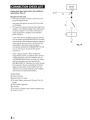
1. Remove the hexagon screws using the supplied
Hexagon Wrench (small). (Fig. 1)
~
Fig. 1
Holes
Gcound leod
Chassis
2. Slide the Top Cover, and lift it to remove. (Fig. 2)
• Be sure not to damage the indicator area.
Fig.3
NOTE:
• To securely connect the ground lead, use an
already installed screw on a metal part of the
vehicle (marked (*))or a clean, bare metal spot
on the vehicle's chassis. Be sure this is a good
ground by checking continuity to the battery H
terminal. Connect all equipment to the same
ground point while keeping wire length as short
as possible. These procedures will help eliminate
noise.
Fig. 2
3. Using the amplifier as a template, mark the four
screw locations.
4. Make sure there are no objects behind the
surface that may become damaged during
drilling.
5. Drill the screw holes.
3 -EN
ATTACHING THE TOP
COVER AND LOGO PLATE
1. Attach the Top Cover after connections and
confirmation of correct operation.
2. Peel the backing paper from the Logo Plate,
then attach it to this unit in your desired
direction. (Fig. 4)
Backing Paper
Logo Plate
Fig. 4
4-EN
CONNECTIONS
.PDR-M65
Fig. 5
• PDR-FSO
Fig. 6
* Be sure to add an in-line fuse with the battery lead as close as possible to the battery's positive(+) terminal.
Before making connections, be sure to turn the
power off to all audio components. Connect the
battery lead from the amp directly to the positive
(+)terminal of the vehicle's battery with
appropriate in-line vehicle's fuse (see Battery Lead
section). Do not connect this lead to the vehicle's
fuse block.
• If you add an optional noise suppressor, connect
it as far away from the unit as possible. Your
Alpine dealer carries various noise suppressors,
contact them for further information.
• Your Alpine dealer knows best about noise
prevention measures so consult your dealer for
further information.
To prevent external noise from entering the
audio system.
• Locate the unit and route the leads at least 10 em
(4") away from the vehicle's harness.
• Keep the battery power leads as far away from
other leads as possible.
• Connect the ground lead securely to a bare metal
spot (remove any paint or grease if necessary) of
the vehicle's chassis.
5-EN
0
Speaker Output Terminals
• The speaker output terminals of this unit are
insert terminal.
Be sure to observe correct speaker output
connections and polarity in relation to the other
speakers in the system. Connect the positive
output to the positive speaker terminal and the
negative to negative.
For PDR-M65
• The input is stereo but the output is monaural.
• Reversing subwoofer polarity may be desirable
in some installations for optimum bass
performance.
About Bridged Connections (For PDR-FSO)
In the bridged mode, connect the left positive to
the positive terminal on the speaker and the
right negative to the negative terminal of the
speaker. Do not use the speaker(-) terminals as
a common lead between the left and right
channels.
Use a Y-adapter (sold separately) for the input
when bridging the outputs. (Refer to the
"BRIDGED CONNECTIONS" on page 13)
NOTE:
• Do not connect the speaker(-) terminal to the
vehicle's chassis.
f) RCA Input Jacks
Connect these jacks to the line out leads on your
head unit using RCA extension cables (sold
separately). Be sure to observe correct channel
connections; Left to Left and Right to Right.
0
Pre-Out Jacks (PDR-M65 only)
These jacks provide a line level output. This is an
ideal output for driving a second subwoofer
amp. This output is full-range, and is not affected
by the crossover.
0Fuse
PDR-M65 ...............................................................35A x 2
PDR-F 50 ................................................................30A x 2
USE THE CORRECT AMPERE RATING WHEN
REPLACING FUSES.
Failure to do so may result in fire or electric
shock.
0
0
Power Supply Terminal
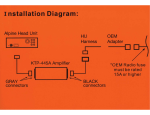
Remote Bass Control (PDR-M65 only)
(Option)
Connect the Remote Bass Control Unit (sold
separately) to adjust the output level remotely.
This is not to replace appropriate gain level
setting between the amplifier and head unit.
6-EN
G Battery Lead (Sold Separately)
Be sure to add an in-line fuse with the battery
lead as close as possible to the battery's positive
(+)terminal. This fuse will protect your vehicle's
electrical system in case of a short circuit. See
below for appropriate fuse value and minimum
wire gauge requirement:
PDR-M65 .................... 70 amp fuse, 4 AWG/21 mm 2
PDR-FSO ..................... 60 amp fuse, 4 AWG/21 mm 2
(i) Ground Lead (Sold Separately)
Connect this lead securely to a clean, bare metal
spot on the vehicle's chassis. Verify this point to
be a true ground by checking for continuity
between that point and the negative(-)
terminal of the vehicle's battery. Ground all your
audio components to the same point on the
chassis to prevent ground loops while keeping
wire length as short as possible.
Minimum required wire gauge for this
connection is as follows:
PDR-M65/PDR-F50 ........................... .4 AWG/21 mm 2
0
Remote Turn-On Lead (Sold Separately)
Connect this lead to the remote turn-on
(positive trigger,(+) 12V only) lead of your head
unit. If a remote turn-on lead is not available, see
"CONNECTION CHECK LIST" section on
page 8 for alternative method.
NOTE:
• When connecting the speaker output leads of
the head unit to this unit with an RCA
extension cable (sold separately), etc., you do
not need to connect the remote turn-on lead,
owing to the "REMOTE SENSING" function of
this unit. However, the "REMOTE SENSING"
function may not work depending on the
signal source connected. In such a case,
connect the remote turn-on lead to an
incoming power supply cord (accessory
power) in the ACC position.
~CAUTION
About Power supply wires
If the length of the power and ground cables
exceed 1 m, or if you connect more than one
amplifier, a distribution block should be used. See
below for wire gauge recommendations for
distribution block connection to battery and
ground (depends upon wire length necessary):
2. Remove the insulation from the ends of the wire
leads by about 7- 10 mm (9/32"- 13/32").
(Fig. 8)
Lead end side of the product
iJ
-]!9/3~~, ~~/32")
PDR-M65/PDR-F50: 2 AWG (33 mm 2 ) or 1/0 AWG
(53 mm 2 )
PDR-M65/PDR-F50
BATTERY
~
lm
(Max.)
Fig. 8
GROUND
:
NOTES:
• If length of the exposed wire is too short, a poor
connection may occur causing operation failure
or sound interruption.
• On the other hand, if the length is too long, an
electrical short-circuit may occur.
4AWG
(21 mm 2)
3. Tighten the set screw with the hexagon wrench
(included) to secure the lead. (Fig. 9)
~~i~~~bution ~~
l
t
To vehicle's
battery
l ~~~~~~~s~~~~r
t
Before making this connection, use insulated
shrink tubing to cover any exposed wire
extending beyond the terminal.
~Hexagon Screw
~Wire Terminal
To vehicle's
chassis*
Fig. 7
* Connect all equipment to the same ground point while
keeping wire length as short as possible.
Ensure that you install a correctly-rated in-line fuse
on the power cable near the battery positive post.
Cautions on wire lead connections
When using third-party wire cables (power supply
wire), use the supplied screws to simplify the
connection. Refer to the description below for the
proper procedure. If you are in doubt about how to
make this connection, consult your dealer.
_;JWire
Fig. 9
NOTES:
• Use only the screws included.
• For safety reasons, connect the battery leads last.
• To prevent disconnection of the leads or
dropping of the unit, do not use the cabling to
carry the unit.
1. Check the wire size.
• Required Wire Size
-Battery Lead/Ground Lead ... .4 AWG (21 mm 2 )
-Remote Turn-On Lead ............. 12 AWG (3 mm 2 )
-Speaker Output Lead:
PDR-M65 ........................................ 8 AWG (8 mm 2)
PDR-F50 ........................................ 12 AWG (3 mm 2 )
• If the wire gauge used is unknown, ask your
dealer.
7-EN
CONNECTION CHECK LIST
Please check your head unit for the conditions
listed below: (Fig. 10)
PDR-M65
PDR-FSO
CD
GV~-------------4-
®
®
Remote Turn-On Lead
a. The head unit does not have a remote turn-on
or power antenna lead.
b. The head unit's power antenna lead is activated
only when the radio is on (turns off in the tape
or CD Mode).
c. The head unit's power antenna lead is logic level
output(+) SV, negative trigger (grounding type),
or cannot sustain(+) 12V when connected to
other equipment in addition to the vehicle's
power antenna.
If any of the above conditions exist, the remote
turn-on lead of your PDR-M65/PDR-FSO must be
connected to a switched power source (ignition)
in the vehicle. Be sure to use a 3A fuse as close
as possible to this ignition tap. Using this
connection method, the PDR-M65/PDR-FSO will
turn on and stay on as long as the ignition
switch is on.
If this is objectionable, a SPST (Single Pole,
Single Throw) switch, in addition to the 3A fuse
mentioned above, may be installed in-line on
the PDR-M65/PDR-FSO turn-on lead. This switch
will then be used to turn on (and off) the
PDR-M65/PDR-FSO. Therefore, the switch should
be mounted so that is accessible by the driver.
Make sure the switch is turned off when the
vehicle is not running. Otherwise, the amplifier
will remain on and drain the battery.
CD Blue/White
® Power Antenna
@Remote Turn-On Lead
QD To other Alpine component's Remote Turn-On
Leads
@ SPST Switch (optional)
®Fuse (3A)
(j) As close as possible to the vehicle's ignition tap
®Ignition Source
B-EN
I
J
®
Fig. 10
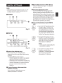
48 Bass EQ Adjustment Knob (PDR-M65 only)
SWITCH SETTINGS
Add a 50 Hz bass boost up to+ 12 dB to tune
your bass response.
NOTE:
• Before switching each Selector Switch, turn off
the power and insert a small screwdriver, etc.,
perpendicularly to the Switch.
48 Input Gain Adjustment Control
Set the PDR-M65/PDR-F50 input gain to the
minimum position. Using a dynamic CD as a
source, increase the head unit volume until the
output distorts. Then, reduce the volume 1 step
(or until the output is no longer distorted). Now,
increase the amplifier gain until the sound from
the speakers becomes distorted. Reduce the
gain slightly so the sound is no longer distorted
to achieve the optimum gain setting.
.PDR-M65
CD
~
48
-~~J~:-~~-<0:>.,-J-~~.=AX
=-48
SUBSONIC
LP FILTER
BASS EQ
GAIN
«D Crossover Mode Selector Switch (PDR-FSO
only)
Fig. 11
~
OFF HP
LP
FILTER
• PDR-FSO
CD
«D
~ ~~- ~;-.....--....,
JFF HP LP
dt----~
- - - I FILTER
CROSSOVER
GAIN
_
W
CHANNEL-112
~
OFF HP
LP
FILTER
50
(Hz)
CHANNEL- 3/4
400
MIN
MAX
80
NOM
,.~. ~· '~I, .e~.
FILTER
CROSSOVER
BASS EQ
GAIN
IJJ
INPUT CHANNEL
~Subsonic Filter (PDR-M65 only)
The subsonic filter for cutting ultra low
frequencies from the input signal before being
amplified.
This is desirable for several reasons:
-To protect speakers too small or not capable
of reproducing ultra low frequencies.
-To minimize power wasted from reproducing
inaudible sound.
-To protect subwoofers in vented enclosures
from over excursion below the tuning
frequency.
b) Set to the "HP" position when the
amplifier is used to drive a tweeter/
midrange system. The frequencies
below the crossover point will be
attenuated at 12 dB/octave.
NOTE:
• In this case the maximum Bass EQ
boost level is reduced.
Ql
Fig. 12
a) Set to the "OFF" position when the
amplifier will be used for driving
full range speakers or when using
an external electronic crossover.
The full frequency bandwidth will
be output to the speakers with no
high or low frequency attenuation.
~
OFF HP
FILTER
LP
c) Set to the "LP" position when the
amplifier is used to drive a
subwoofer. The frequencies above
the crossover point will be
attenuated at 12 dB/octave.
CD Crossover Frequency Adjustment Knob
(PDR-M65: LP FILTER)
Use this control to adjust the crossover
frequency between 50 to 400Hz.
9-EN
C9 Bass EQ Selector Switch (CH-3/4) (PDR-FSO
only)
Set to +6 dBII or II+ 12 dB" position when using
for driving a subwoofer.
The center frequency is 50 Hz.
11
4D Input Channel Selector Switch (PDR-FSO only)
~
1/2 3/4
INPUT CHANNEL
~
1/2 3/4
INPUT CHANNEL
a) This switch setting is for selecting
either 2-channel or 4-channel input
mode. When set to 1/2': signal will
be copied from CH-1 /2 and sent to
CH-3/4, eliminating the need for
Y-adapters.
11
11
b) Setting this switch to 3/4" will keep
both inputs, CH-1/2 and CH-3/4
independent.
A 4-channel source is required for
this mode.
About Power Indicator
Power Indicator
Fig. 13
Lights up when power is on.
Is off when power is off.
Indication color
Status
Solution
Blue
Amplifier circuit is normal.
Red
(blinking)
Operating temperature is
high.
Decrease the vehicle's interior temperature to a
normal level.
The indicator color changes to blue.
Red
Amplifier circuit is abnormal.
An electrical short has
occurred, or supply current is
too high.
Turn off the power supply and eliminate the cause.
Then turn on the unit and verify that the indicator
color has changed to blue.
If it remains red, turn off the unit and consult your
dealer.
Operating temperature is too
high.
Decrease the vehicle's interior temperature to a
normal level.
The indicator color changes to blue.
Power supply voltage is too
high.
Use the correct power supply voltage.
The indicator color changes to blue.
10-EN
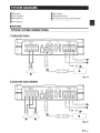
SYSTEM DIAGRAMS
fD Subwoofer
G) Front Speakers
G) Rear Speakers
~Head Unit, etc.
~ Front Output
~ Rear Output
~ Subwoofer Output
RCA Extension Cable (Sold Separately)
f) Y-Adapter (Sold Separately)
e
.PDR-M65
TYPICAL SYSTEM CONNECTIONS
1 Subwoofer System
Fig. 14
2 Subwoofer System {MONO)
Fig. 1S
11-EN
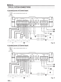
• PDR-FSO
TYPICAL SYSTEM CONNECTIONS
4 Speaker System (4-Channellnput)
1=-:Jtl
Input Channel Selector Switch: 3/4
1/2 3/4
INPUT CHANNEL
8
(L)
L
R
L
f)
R
Fig. 16
4 Speaker System (2-Channellnput)
'J2
Input Channel Selector Switch: 1/2
1/2 3/4
INPUT CHANNEL
(R)
(L)
L
R
L
f)
R
Fig. 17
12-EN
BRIDGED CONNECTIONS
2 Speaker+ Subwoofer System
1-=:Jtl
Input Channel Selector Switch: 3/4
I
1/2 3/4
INPUT CHANNEL
+
CH-1
+
SPEAKER OUTPUT
CH-2
Ct+-3
®
+
CH-4
CH-l(L)
,
CH- 3 (Ll
30A
POWER SUPPLY
®
30A
~ c . .. ,,~~~rn,,, = ~riNPU~r .
~fr .~, "~~ND~:JJ:::::::t7
lt
YU
(L)
(R)
(R)
(L)
~
8
(±)
+
~®~ ~ E:l!l ~~
:-::-::-::-:
'-'---...........=
FUSE
~
8
F======O:Q)0
--
~G)
(L)
(R)~
(R)
(L)
L
9
R
Fig. 18
Important Tips on Bridging an Amplifier
NOTE:
• Low output will result if only one channel input is used. TheY-adapter is not required if a stereo/mono pair
line output is used to drive both inputs of the bridged amp.
0
X
Proper connection
Improper connection
i
T~~
~
(One signal)
Fig. 19
13-EN
SPECIFICATIONS
PDR-FSO
PDR·M6S
Performance
Power Output
Per Channel, Ref: 4 0, 14.4 V
450W RMS
X
1
85WRMSx4
Per Channel, Ref: 2 0, 14.4 V
650W RMS
X
1
125 W RMS x4
Bridged, Ref: 4 0, 14.4 V
S/N Ratio
Frequency Response
Damping Factor
250W RMS
~0.02%
~0.02%
Ref: lOW into 2 0
~0.03%
~0.03%
Ref: Rated Power into 4 0
~0.07%
~0.07%
Ref: Rated Power into 2 0
~0.09%
~0.09%
IHF A-wtd + AES-17
Ref: 1W into 4 0
>87 dB
>87 dB
IHF A-wtd + AES-17
Ref: Rated Power into 4 0
> 113 dB
>106 dB
Ref: 10 W into 4 0
THD+N
..
X
2
+0/-3 dB, Ref: 1 W into 4 0
8Hz-400Hz
8Hz-45kHz
+0/-1 dB, Ref: 1 W into 4 0
10Hz-300Hz
10Hz-30kHz
>1,500
>500
-
CH-3/4:
CH-1/2 or CH-3/4
Ref: 10 W into 4 0 at 100Hz
Control
Input Select
Selectable Input Signal
Configuration (2ch/4ch Input)
Input Sensitivity
RCA Input
Ref: Rated Power into 4 0
0.1 -4.0
v
0.2 -4.0V
Variable HPF/LPF
LPF: 50 Hz- 400 Hz
(-24 dB/oct.)
50 Hz- 400Hz
(-12 dB/oct.)
Variable Subsonic
8Hz-40Hz
(-24 dB/oct.)
-
Equalizer
Bass EQ (fc=50 Hz)
Oto+12dB
(Variable)
CH-3/4: 0 or +6 or+ 12 dB
(Selectable)
Remote Level*
Linear Attenuation
* Requires optional RUX-KNOB
0 to -20 dB
-
Crossover
General
>10 kO
Input Impedance
Preamp Output
Dimensions
CH-1 /2 Input Pass-through,
Buffered
4Vmax
Width
228.5 mm (9")
Height
50.8 mm (2")
165 mm (6-1 /2")
Depth
Weight
2.4 kg (5 lb 5 oz)
NOTE:
• Specifications and design are subject to change without notice.
14-EN
-
I
I
2.5 kg (5 lb 9 oz)
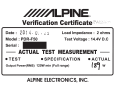
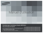
~LPINE®
Verification Certificate PAs.::;;.·:,
20 1 4 . 0i
Date :
Model : PDR-F50
• Lb
Load Impedance : 2 ohms
Test Voltage : 14.4V D.C
Serial :
-
ACTUAL TEST MEASUREMENT
•TEST
• SPECIFICATION
•ACTUAL
Output Power(RMS) 125W min (Full range)
ALPINE ELECTRONICS, INC.
'8'1 w
Thank you for choosing Alpine for your car audio equipment needs. Our goal is to
produce the best audio/video/navigation products in the world and hope your
expectations are met.
Please take a moment to protect your purchase by registering your product now at
the following address: www.alpine-usa.com/registration. You will be informed of
product and software updates (if applicable), special promotions, and news about
Alpine. Also, by registering your product, you will automatically be entered for a
chance to win various prizes such as gift cards, Alpine products, and/or a complete
system.
We look forward to continue serving you in the future.
Sincerely,
The Alpine Team
French
Spanish
Nous vous remercions d'avoir porte votre choix sur un
equipement audio automobile Alpine. Notre principal
objectif est de fabriquer les meilleurs produits audio,
video et de navigation au monde afin de repondre aux
exigences de nos clients.
Gracias por elegir Alpine para las necesidades de
equipamiento de audio de su vehfculo. Nuestro
objetivo es fabricar los mejores productos de audio/
vfdeo/navegaci6n del mundo y esperamos poder
cumplir sus expectativas.
Veuillez prendre quelques instants pour securiser
votre achat en enregistrant votre produit l'adresse
suivante : www.alpine-usa.com/registration. Vous
serez tenu informe des nouveaux produits, des mises
a jour logicielles (le cas echeant) , des promotions
speciales et des informations concernant Alpine.
L'enregistrement de votre produit vous donne par
ailleurs Ia possibilite de gagner des dizaines de
cadeaux, tels que cheques-cadeaux et articles Alpine,
ainsi qu'un systeme complet.
Dedique unos momentos a proteger su compra:
registre ahora su producto en Ia siguiente direcci6n:
www.alpine-usa.com/registration. Recibira
informacion de novedades sobre el producto y
actualizaciones de software (si se producen),
promociones especiales y noticias de ultima hora de
Alpine. Asimismo, si registra su producto, entrara
automaticamente en el sorteo de diversos premios,
como tarjetas de regalo, productos de Alpine y/o un
sistema completo.
Nous esperons que nos produits vous donneront
entierement satisfaction.
Esperamos poder seguir ofreciendole el mejor
servicio en el futuro.
Cordialement,
Atentamente,
L'equipe Alpine
El equipo de Alpine
a
PART NO. 68-21627Z36-A
M354415301 0
//#b'ILPINE®
GARANTIE LIMITEE
a
Fideles leur engagement de ne fournir que des produits de qualite, ALPINE ELECTRONIQUE DE L'AMERIQUE, INC. et
ALPINE ELECTRONIQUE DU CANADA, INC. (Alpine) sont heureuses de vous offrir cette garantie. Nous vous suggerons dele
lire attentivement et en entier. Si vous avez Ia moindre question, veuillez contacter l'un de nos concessionnaires ou appeler
directement Alpine aux numeros listes ci-dessous.
®
ePRODUITS COUVERTS PAR LA GARANTIE
Cette garantie couvre les produits audio de voiture et les
accessoires connexes ("le produit"). Ellene couvre les
produits que dans le pays ou ils ont ete achetes.
eDUREE DE LA GARANTIE
Cette garantie est en vigueur pendant un an
du premier achat du client.
a partir de Ia date
Vous devez donner une description detaillee des
problemas qui sont a l'origine de votre demande de
reparation.
® Vous devez joindre Ia preuve de votre achat du produit.
@ Vous devez emballer soigneusement le produit pour eviter
tout dommage durant son transport. Pour eviter Ia perte
de I' envoi, il est conseille de choisir un transporteur qui
propose un service de suivi des envois.
ePERSONNES PROTEGEES PAR LA GARANTIE
eLIMITATION DES GARANTIES TACITES
Seull'acheteur original du produit, s'il resisde aux Etats-Unis,
Porto Rico ou au Canada, peut se prevaloir de Ia garantie.
LA DUREE DE TOUTES LES GARANTIES TACITES, Y
COMPRIS LA GARANTIE D'ADAPTATION A L'UTILISATION
ET LA GARANTIE DE QUALITE LOYALE ET MARCHANDE,
EST LIMITEE A CELLE DE LA GARANTIE EXPRESSE
DETERMINEE CI-DESSUS. PERSONNE N'EST AUTORISE
A ENGAGER AUTREMENT LA RESPONSABILITE D'ALPINE
EN VERTU DE LA VENTE D'UN PRODUIT.
a
eCE QUI EST COUVERT
Cette garantie couvre tous les defauts de materiaux et de
fabrication (pieces et main d'ceuvre) du produit.
eCE QUI N'EST PAS COUVERT
Cette garantie ne couvre pas ce qui suit:
Les dommages survenus durant le transport des produits
renvoyes Alpine pour etre repares (les reclamations
doivent etre adressees au transporteur);
® Les degats provoques par un accident ou une mauvaise
utilisation, y compris des bobines acoustiques grillees
suite a une surexcitation des enceintes (augmentation
du niveau de l'amplificateur jusqu'a atteindre un effet de
distorsion ou d'ecn3tage), une defaillance mecanique
des enceintes (perforations, dechirures ou fentes),
panneaux LCD fissures ou endommages, disques durs
endommages ou ayant subi une chute.
® Tout degat provoque par negligence, usage inapproprie,
mauvaise utilisation ou par le non-respect des
instructions indiquees dans le manuel de l'utilisateur.
@ Les dommages dus Ia force majeure, notamment aux
tremblements de terre, au feu, aux inondations, aux
tempetes ou aux autres cataclysmes naturels;
Les frais ou les depenses relatifs l'enlevement ou Ia
reinstallation du produit;
@ Les services rendus par une personne, physique ou
morale non autorisee;
® Les produits dont le numero de serie a ete efface, modifie
ou retire;
0 Les produits qui ont ete adaptes ou modifies sans le
consentement d'Aipine;
® Les produits qui ne sont pas distribues par Alpine aux
Etats-Unis, Porto Rico ou au Canada;
® Les produits qui n'ont pas ete achetes par l'entremise d'un
concessionnaire Alpine autorise;
CD
a
a
a
a
a
eCOMMENT SE PREVALOIR DE LA GARANTIE
CD
II vous faut remettre le produit necessitant des reparations
a un centre de service autorise Alpine ou a Alpine meme et
en assumer les frais de transport. Alpine a le choix entre
reparer le produit ou le remplacer par un produit neuf ou
revise, le tout sans frais pour vous. Si les reparations sont
couvertes par Ia garantie et si le produit a ete envoye un
centre de service Alpine ou Alpine, le paiement des frais
de reexpedition du produit incombe Alpine.
a
a
eEXCLUSIONS DE LA GARANTIE
ALPINE STIPULE EXPRESSEMENT QU'ELLE N'EST PAS
RESPONSABLE DES DOMMAGES-INTERETS ET
DOMMAGES INDIRECTS PROVOQUES PARLE PRODUIT.
LES DOMMAGES-INTERETS SONT LES FRAIS DE
TRANSPORT DU PRODUIT VERS UN CENTRE DE
SERVICE ALPINE, LA PEATE DE TEMPS DE L'ACHETEUR
ORIGINAL, LA PEATE D'UTILISATION DU PRODUIT, LES
BILLETS D'AUTOBUS, LA LOCATION DE VOITURES ET
TOUS LES AUTRES FRAIS LIES A LA GARDE DU
PRODUIT.
LES DOMMAGES INDIRECTS SONT LES FRAIS DE
REPARATION OU DE REMPLACEMENT D'AUTRES BIENS
ENDOMMAGES SUITE AU MAUVAIS FONCTIONNEMENT
DU PRODUIT.
LES RECOURS PREVUS PAR LES PRESENTES
EXCLUENTETREMPLACENTTOUTEAUTREFORMEDE
RECOURS.
ellEN ENTRE LA GARANTIE ET LA LOI
La garantie vous donne des droits specifiques, mais vous
pouvez aussi jouir d'autres droits, qui varient d'un etat ou
d'une province l'autre. En outre, certains etats et certaines
provinces interdisent de limiter Ia duree des garanties tacites
ou d'exclure les dommages accessoires ou indirects. Dans ce
cas, les limites et les exclusions de Ia garantie peuvent ne pas
s'appliquer vous.
a
a
eCLAUSE APPLICABLE AU CANADA SEULEMENT
Pour que Ia garantie soit valable, il taut qu'un centre
d'installation autorise ait installs le systeme audio pour l'auto
dans votre vehicule et qu'il ait ensuite appose son cachet sur
Ia garantie.
eNUMEROS D'APPEL DU SERVICE
A LA CLIENTELE
Si vous avez besoin de nos services, veuillez appeler Alpine
aux numeros ci-dessous pour le centre de service autorise
Alpine le plus proche.
AUDIO DE VOITURE
NAVIGATION
1-800-ALPINE-1 (1-800-257-4631)
1-888-NAV-HELP (1-888-628-4357)
Ou visitez notre site Web
a l'adresse http://www.alpine-usa.com
ALPINE ELECTRONIQUE DE L'AMERIQUE, INC., 19145 Gramercy Place, Torrance, California 90501, U.S.A.
ALPINE ELECTRONIQUE DU CANADA, INC., 777 Supertest Road, Toronto, Ontario M3J 2M9, Canada
N'envoyez aucun produit a ces adresses.
Appelez notre numero gratuit ou visitez notre site Web si vous recherchez un centre de service.
ffffh'ILPINE@
LIMITED WARRANTY
ALPINE ELECTRONICS OF AMERICA, INC. AND ALPINE OF CANADA INC. ("Alpine"), are dedicated to quality
craftsmanship and are pleased to offer this Warranty. We suggest that you read it thoroughly. Should you have any
questions, please contact your Dealer or contact Alpine at one of the telephone numbers listed below.
This Warranty covers Car Audio Products and Related
Accessories ("the product"). Products purchased in the
Canada are covered only in the Canada. Products
purchased in the U.S.A. are covered only in the U.S.A.
® You must supply proof of your purchase of the product.
@You must package the product securely to avoid
damage during shipment. To prevent lost packages it is
recommended to use a carrier that provides a tracking
service.
eLENGTH OF WARRANTY:
eHOW WE LIMIT IMPLIED WARRANTIES:
This Warranty is in effect for one year from the date of the
first consumer purchase.
This Warranty only covers the original purchaser of the
product, who must reside in the United States, Puerto Rico
or Canada.
ANY IMPLIED WARRANTIES INCLUDING FITNESS FOR
USE AND MERCHANTABILITY ARE LIMITED IN
DURATION TO THE PERIOD OF THE EXPRESS
WARRANTY SET FORTH ABOVE AND NO PERSON IS
AUTHORIZED TO ASSUME FOR ALPINE ANY OTHER
LIABILITY IN CONNECTION WITH THE SALE OF THE
PRODUCT.
eWHAT IS COVERED:
eHOW WE EXCLUDE CERTAIN DAMAGES:
This Warranty covers defects in materials or workmanship
(parts and labor) in the product.
ALPINE EXPRESSLY DISCLAIMS LIABILITY FOR
INCIDENTAL AND CONSEQUENTIAL DAMAGES
CAUSED BY THE PRODUCT. THE TERM "INCIDENTAL
DAMAGES" REFERS TO EXPENSES OF
TRANSPORTING THE PRODUCT TO THE ALPINE
SERVICE CENTER, LOSS OF THE ORIGINAL
PURCHASER'S TIME, LOSS OF THE USE OF THE
PRODUCT, BUS FARES, CAR RENTALS OR OTHERS
COSTS RELATING TO THE CARE AND CUSTODY OF
THE PRODUCT. THE TERM "CONSEQUENTIAL
DAMAGES" REFERS TO THE COST OF REPAIRING OR
REPLACING OTHER PROPERTY WHICH IS DAMAGED
WHEN THIS PRODUCT DOES NOT WORK PROPERLY.
THE REMEDIES PROVIDED UNDER THIS WARRANTY
ARE EXCLUSIVE AND IN LIEU OF ALL OTHERS.
ePRODUCTS COVERED:
eWHO IS COVERED:
eWHAT IS NOT COVERED:
This Warranty does not cover the following:
CD Damage occurring during shipment of the product to
Alpine for repair (claims must be presented to the
carrier).
® Damage caused by accident or abuse, including burned
voice coils caused by over-driving the speaker (amplifier
level is turned up and driven into distortion or clipping).
Speaker mechanical failure (e.g. punctures, tears or
rips). Cracked or damaged LCD panels. Dropped or
damaged hard drives.
® Damage caused by negligence, misuse, improper
operation or failure to follow instructions contained in the
Owner's manual.
@ Damage caused by act of God, including without
limitation, earthquake, fire, flood, storms or other acts of
nature.
Any cost or expense related to the removal or
reinstallation of the product.
® Service performed by an unauthorized person, company
or association.
® Any product which has the serial number defaced,
altered or removed.
(j) Any product which has been adjusted, altered or
modified without Alpine's consent.
® Any product not distributed by Alpine within the United
States, Puerto Rico or Canada.
® Any product not purchased from an Authorized Alpine
Dealer.
eHOW STATE/PROVINCIAL LAW RELATES TO THE
WARRANTY:
This Warranty gives you specific legal rights, and you may
also have other rights which vary from state to state and
province to province. In addition, some states/provinces do
not allow limitations on how long an implied warranty lasts,
and some do not allow the exclusion or limitation of
incidental or consequential damages. Accordingly,
limitations as to these matters contained herein may not
apply to you.
eiN CANADA ONLY:
This Warranty is not valid unless your Alpine car audio
product has been installed in your vehicle by an Authorized
Installation Center, and this warranty stamped upon
installation by the installation center.
eHOW TO OBTAIN WARRANTY SERVICE:
eHOW TO CONTACT CUSTOMER SERVICE:
CD
Should the product require service, please call the following
number for your nearest Authorized Alpine Service Center.
You are responsible for delivery of the product to an
Authorized Alpine Service Center or Alpine for repair
and for payment of any initial shipping charges. Alpine
will, at its option, repair or replace the product with a
new or reconditioned product without charge. If the
repairs are covered by the warranty, and if the product
was shipped to an Authorized Alpine Service Center or
Alpine, Alpine will pay the return shipping charges.
®You should provide a detailed description of the
problem(s) for which service is required.
CAR AUDIO 1-800-ALPINE-1 (1-800-257-4631)
NAVIGATION 1-888-NAV-HELP (1-888-628-4357)
Or visit our website at; http://www.alpine-usa.com
ALPINE ELECTRONICS OF AMERICA, INC., 19145 Gramercy Place, Torrance, California 90501, U.S.A.
ALPINE ELECTRONICS OF CANADA, INC., 777 Supertest Road, Toronto, Ontario M3J 2M9, Canada
Do not send products to these addresses.
Call the toll free telephone number or visit the website to locate a service center.
68-00493Z72-A (Y)
M3544091 010