1
Copley
Controls
Corp.
Accelnet Micro Panel
™
DIGITAL SERVOAMPLIFIER
for BRUSHLESS or BRUSH MOTORS
MOTOR CONNECTIONS
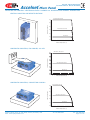
Motor connections are of four types: phase, Halls, encoder and thermal sensor. The phase connections carry the amplifier output
currents that drive the motor to produce motion. The Hall signals are three digital signals that give absolute position feedback
within an electrical commutation cycle. The encoder signals give incremental position feedback and are used for velocity and
position modes, as well as sinusoidal commutation. A thermal sensor that indicates motor overtemperature is used to shut down
the amplifier to protect the motor.
+5V
Motor Temperature Sensor
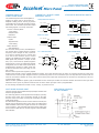
Digital input [IN5] is for use with a motor overtemperature switch. The
input should be programmed as a pull-up to +5 Vdc if the motor switch is
grounded when cold, and open or high-impedance when over-heating.
4.99 k
74HC14
10 k
[IN5]
3.3 nF
MOTOR ENCODER
The input circuit for the motor encoder signals is a differential line-receiver
with R-C filtering on the inputs. A 121 Ω resistor is across each input pair
to terminate the signal pairs in the cable characteristic impedance. The
circuit is shown below. Encoders with differential outputs are required
because they are less susceptible to noise that can be picked on singleended outputs. For best results, encoder cabling should use twisted pair
cable with one pair for each of the encoder outputs: A-/A, B-/B, and X-/X.
Shielded twisted-pair is even better for noise rejection.
22 pF
+5V
2k
1k
A, B, X
ENC
/A, /B, /X
121
1k
MOTOR HALL SIGNALS
U
W
HALL
26LS32
22 pF
+5V
V
Hall signals are single-ended signals that provide absolute feedback within
one electrical cycle of the motor. There are three of them (U, V, & W) and
they may be sourced by magnetic sensors in the motor, or by encoders
that have Hall tracks as part of the encoder disc. They typically operate at
much lower frequencies than the motor encoder signals, and are used for
commutation-initialization after startup, and for checking the motor phasing
after the amplifer has switched to sinusoidal commutation.
+
10 k
10 k
U, V, W
74HC14
3.3 nF
+5 Vdc
Motor Brake
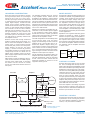
Digital outputs [OUT1,2,3,4] can be programmed to power a motor-mounted
brake. These brake the motor when they are in an unpowered state and
must have power applied to release. This provides a fail-safe function that
prevents motor motion if the system is in an unpowered (uncontrolled)
state. Because brakes are inductive loads, an external flyback diode must
be used to control the coil voltage when power is removed. The timing of
the brake is programmable.
[OUT1] [OUT2]
[OUT3], or [OUT4]
motor phase connections
+HV
Input
The amplifier output is a three-phase PWM inverter that converts the DC
buss voltage (+HV) into three sinusoidal voltage waveforms that drive the
motor phase-coils. Cable should be sized for the continuous current rating
of the amplifier. Motor cabling should use twisted, shielded conductors for
CE compliance, and to minimize PWM noise coupling into other circuits.
The motor cable shield should connect to motor frame and the amplifier
frame ground terminal (J2-1) for best results.
PWM
Outputs
= Shielded cables required
for CE compliance
Copley Controls Corp., 20 Dan Road, Canton, MA 02021, USA
Web: www.copleycontrols.com
BRAKE
1k
+
24 Vdc
-
Gnd
Tel: 781-828-8090 Mot U
U
Mot V
V
Mot W
W
MOTOR
Shld
Fax: 781-828-6547
Page of 14