1
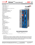
Xenus XTL
DIGITAL SERVO DRIVE
for BRUSHLESS/BRUSH MOTORS
XTL
RoHS
GENERAL SPECIFICATIONS
Test conditions: Wye connected load: 2 mH line-line. Ambient temperature = 25 °C. Power input = 230 Vac, 60 Hz, 1 Ø
MODEL
XTL-230-18 XTL-230-36
XTL-230-40
Same specs for -S and -R models
Output CURRENT
Peak Current
18 (12.7)
36 (25.5)
40 (28.3)
Adc (Arms, sinusoidal)
Peak time
111
s
Continuous current (Note 1)
6 (4.24)
12 (8.5)
20 (14.1)
Adc (Arms, sinusoidal)
INPUT POWER
Mains voltage, phase, frequency
100~240
Vac, ±10%, 1 Ø or 3 Ø, 47~63 Hz
Maximum Mains Current, 1Ø (Note 3)
10.120.020.0 Arms
Maximum Mains current, 3Ø (Note 3)6.4
10.4
15.4
Arms
+24 Vdc Control power
+20 to +32 Vdc, 500 mA max
Required for operation
DIGITAL CONTROL
Digital Control Loops
Current, velocity, position. 100% digital loop control
Sampling rate (time)
Current loop: 15 kHz (67 µs), Velocity & position loops: 3 kHz (333 µs)
Commutation
Sinusoidal field-oriented control or trapezoidal for brushless motors
Bandwidth
Current loop: 2.5 kHz typical, bandwidth will vary with tuning & load inductance
Bus voltage compensation
Changes in bus or mains voltage do not affect bandwidth
Minimum load inductance
200 µH line-line
command inputs (Note: Digital input functions are programmable)
Distributed Control Modes
CANopen
Position, Velocity, Torque, Homing, Profile, and Interpolated profile modes
ASCII
Multiple drives accessible from a single RS-232 port
Stand-alone mode
Analog torque, velocity, position reference
±10 Vdc, 12 bit resolution
Dedicated differential analog input
Input impedance
74.8 kΩ
Between Ref(+), Ref(-)
Digital position reference
Pulse/Direction, CW/CCW
Stepper commands (2 MHz maximum rate)
Quad A/B Encoder
2 M line/sec, 8 Mcount/sec (after quadrature)
Digital torque & velocity reference
PWM , Polarity
PWM = 0% - 100%, Polarity = 1/0
PWM 50%
PWM = 50% ±50%, no polarity signal required
PWM frequency range
1 kHz minimum, 100 kHz maximum
PWM minimum pulse width
220 ns
Indexing
Up to 32 programs can be launched from inputs or ASCII commands. Each program can
consist of moves, I/O commands, time delays, and other programmable operations.
Camming
Master quadrature encoder provides position as index to cam table.
Digital inputs initiate cam functions.
DIGITAL inputs
12
Number
Inputs [IN1~5,11,12]
74HC14 Schmitt trigger, 330 µs RC filter, Vin-LO < 1.35 Vdc, Vin-HI >3.65 Vdc, +24 Vdc max
[IN1] dedicated to drive enable function, other inputs are programmable
Input [IN6]
74HC14 Schmitt trigger, 100 ns RC filter, Vin-LO < 1.35 Vdc, Vin-HI >3.65 Vdc, +12 Vdc max
Inputs [IN7~10]
Single-ended: Comparator with 2.5 Vdc reference, 100 ns RC filter, Vin-LO <2.3 Vdc, Vin-HI > 2.45 Vdc
Differential: RS-485 line receiver on input pairs [IN9-7], and [IN10-8], 100 ns RC filters, +12 Vdc max
All inputs
10 kΩ pull-up to +5 Vdc or pull-down to ground, selectable in groups, active level programmable
digital outputs (Note 2)
Number
[OUT1], [OUT2], [OUT3]
Current rating
Brake [OUT4]
multi-mode encoder port
As Input
As Output
RS-232 PORT
Signals
Mode
Protocol
CAN PORTS
Signals
Format
Data
Address selection
status indicators
Drive Status
CAN Status
REGENERATION
Operation
Cut-In Voltage
Drop-Out Voltage
Tolerance
4
Current-sinking MOSFET with 1 kΩ pullup to +5 Vdc through diode
1 Adc max, +40 Vdc max. Functions programmable
External flyback diode required if driving inductive loads
Opto-isolated, current-sinking with flyback diode to +24 Vdc, 1 Adc max
Secondary digital quadrature encoder (A, /A, B, /B, X, /X), 121 Ω terminating resistors
18 M-counts/sec, post-quadrature (4.5 M-lines/sec)
Primary increment encoder for models with -S option that use sin/cos signals as analog Halls
Quadrature encoder emulation with programmable resolution to 4096 lines (65,536 counts) per rev
from analog sin/cos encoders or resolvers. Buffered signals from digital quad A/B/X primary encoder
A, /A, B, /B, X, /X, from 26C31 differential line driver
RxD, TxD, Gnd in 6-position, 4-contact RJ-11 style modular connector
Full-duplex, DTE serial communication port for drive setup and control, 9,600 to 115,200 baud
Binary and ASCII formats
CANH, CANL, Gnd in 8-position RJ-45 style modular connector, wired as per CAN Cia DR-303-1, V1.1
CAN V2.0b physical layer for high-speed connections compliant
CANopen Device Profile DSP-402
16 position rotary switch on front panel with 3 additional address bits available as
digital inputs or programmable to flash memory (7-bit addressing, 127 nodes per CAN network)
Bicolor LED, drive status indicated by color, and blinking or non-blinking condition
Bicolor LED, status of CAN bus indicated by color and blink codes to CAN Indicator Specification 303-3
Internal solid-state switch drives external regen resistor (see Ordering Guide for types)
+HV > 390 Vdc
Regen output is on, (optional external) regen resistor is dissipating energy
+HV < 380 Vdc
Regen output is off, (optional external) regen resistor not dissipating energy
±2 Vdc
For either Cut-In or Drop-Out voltage
Notes:
1. Heatsinking and/or forced-air cooling is required for continuous output power rating
2. Brake[OUT4] is programmable as motor brake, or as general purpose digital output
3. The actual mains current is dependent on the mains voltage, number of phases, and motor load and operating conditions.
The Maximum Mains Currents shown above occur when the drive is operating from the maximum input voltage and is producing
the rated continuous output current at the maximum output voltage.
Copley Controls, 20 Dan Road, Canton, MA 02021, USA
Tel: 781-828-8090
Tech Support: E-mail: [email protected], Internet: http://www.copleycontrols.com
Fax: 781-828-6547
Page 2 of 30