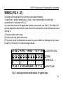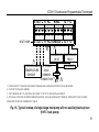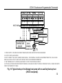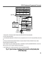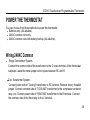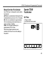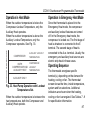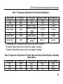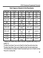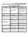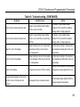
1
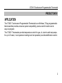
CT2001 Touchscreen
Programmable Thermostat
WED
PM
Room
Running As SCHED
SYSTEM HEAT
FAN
AUTO
AUTO
MORE
SCHED
HOLD
CLOCK SCREEN
CT2001 Touchscreen Programmable Thermostat
Contents
Application/Features................................................................................................................2
Specifications/Ordering Information........................................................................................ 4
Installation..............................................................................................................................14
Wiring.....................................................................................................................................18
Power the Thermostat............................................................................................................35
Installer Setup.........................................................................................................................48
Installer System Test...............................................................................................................59
Operation................................................................................................................................62
Programming ..........................................................................................................................64
Troubleshooting .…..................................................................................................................92
1t
CT2001 Touchscreen Programmable Thermostat
PRODUCT DATA
APPLICATION
The CT2001 Touchscreen Programmable Thermostat is an effortless, 7-Day programmable
thermostat that provides universal system compatibility, precise comfort control and is
easy-to-program.
The CT2001 Thermostats provide temperature control for gas, oil, electric and heat pumps
for up to 3 heats, 2 cool systems including dual fuel operation plus dehumidification control.
2t
CT2001 Touchscreen Programmable Thermostat
FEATURES
Large, clear display with backlight shows the current and set temperature and
thermostat in the dark.
Menu-driven programming make setup effortless.
Beautiful ergonomic design is smart and sophisticated to match your customer
lifestyle.
Touchscreen interaction
Real-time clock keeps time during power failures and automatically updates to
daylight savings.
"Saving Changes" notification lets you know when the schedule changes have been
saved.
Change/check reminders let you know when to service or replace filters or batteries
Various Hold options allow you to override the program schedule, as desired.
Armchair programming allows you to remove the thermostat from the wall for
programming.
3
CT2001 Touchscreen Programmable Thermostat
SPECIFICATIONS
Thermostat Description:
Feature
Powering methods
System types (up to3 heat/2 cool)
Description
Common wire with battery backup
Gas, oil or electric heat with air conditioning
Warm air, hot water, high-efficiency furnaces, heat
pumps, steam and gravity
Heat only includes power to open and power to
close zone valves and normally-open
zone valves
Heat only with fan
Cool only
750 mV heating systems
Changeover
Manual or Auto changeover selectable
System setting
HEAT-OFF-COOL-AUTO (EMER for heat pumps)
Fan setting
AUTO-ON-CIRC
4
CT2001 Touchscreen Programmable Thermostat
Electrical Ratings:
Terminal
Voltage (50/60 Hz)
Running Current
W Heating
20 - 30 VAC
1 AMP max.
W Heating (Power pile)
750 mVDC
100 mAMP
Y Cooling
20 - 30 VAC
1 AMP max.
G Fan
20 - 30 VAC
1 AMP max.
Temperature Setting Range:
Heating: 40°F to 90°F (4°C to 32°C).
Cooling: 50°F to 99°F (10°C to 37°C).
Operating Ambient Temperature:
32°F to 120°F (0°C to 49°C).
Shipping Temperature:
CT2001 Thermostats: -30 °F to 150 °F
(-34.4°C to 65.6°C).
5
CT2001 Touchscreen Programmable Thermostat
Operating Relative Humidity (Non-condensing):
CT1002 Thermostats: 5% to 90%.
IAS-1: 5% to 95%.
OAS-1: 5% to 95%.
Humidity Setting Range (CT1002 models only):
Cooling: 40% to 80% RH.
Humidity Display Range (CT1002 models only):
0% to 99%.
Cycle Rates (at 50% Load):
Heating: Selectable 1 - 12 cycles per hour.
Cooling: Selectable 1 - 6 cycles per hour.
Clock Accuracy: +/- 1 minute per month.
Batteries:
Two replaceable AA alkaline batteries will power the thermostat when 24VAC common is not
used. A non-replaceable lithium battery with ten-year life is inside the thermostat. Under
normal use the lithium battery will maintain the calendar and time settings. The Alkaline
batteries maintain the calendar and time after lithium battery is no longer functional.
6
CT2001 Touchscreen Programmable Thermostat
Cool Indication:
CT2001 Touchscreen Thermostats show "Cool On" on the screen when Cool is activated.
Heat Indication:
CT2001 Touchscreen Thermostats show "Heat On" on the screen when Heat is activated.
Auxiliary Heat Indication:
CT2001 Touchscreen Thermostats show "Aux Heat On" on the screen when Auxiliary Heat is
activated.
Emergency Heat Indication:
CT2001 Touchscreen Thermostats show "Heat On" on the screen when Emergency Heat is
activated and the System mode is in the EMER position.
Calibration:
CT2001 Touchscreen Thermostats are factory-calibrated and require no field calibration.
7
CT2001 Touchscreen Programmable Thermostat
ORDERING INFORMATION
If you have additional questions, need further information, or would like to comment on our
products or services, please write or phone: [email protected] or
866-792-2022
8
CT2001 Touchscreen Programmable Thermostat
Nomenclature:
Series
CT2001
System Stages
3H/2C
Application
CT2001 - Standard
Mounting Means:
CT2001 Touchscreen Thermostat: Mounts directly on the wall in the living space using
mounting screws and anchors provided.
Outdoor Sensor: Mounts outside of living space with mounting clip and screws provided.
Remote Indoor Sensor: Mounts directly on the wall using mounting screws and anchors
provided.
Dimensions:
1. CT2001 Touchscreen Thermostat: see Fig 1.
2. CT2001 Touchscreen Thermostat Back Case: see Fig. 2
3. CT2001 Outdoor Sensor Mounting Clip: see Fig 3.
4. CT2001 Cover Plate: see Fig 4.
9
CT2001 Touchscreen Programmable Thermostat
1.235 in.(30.60mm)
4.48in. (114mm)
5.98 in.(152mm)
Fig. 1. Touchscreen Thermostat dimensions in inches. (mm).
10
CT2001 Touchscreen Programmable Thermostat
1.77 in.(45mm)
0.84 in .(21.5mm)
1.67 in.(42.5mm)
1.51 in.(38.5mm)
Fig. 2. Touchscreen Thermostat Back Case dimensions in inches. (mm).
11
.
7in
0.1
1.82 in.(46.3mm)
0.08 in.(2mm)
R0
m)
2m
(4.
1.49 in.(38mm)
1.10 in.(28.1mm)
CT2001 Touchscreen Programmable Thermostat
.09
8i
n.(
m
4m
m
)
m
.(1
in
1.56 in .(39.7mm)
in.
(
mm
2.5
4
.0
R0
R1
.6
)
)
0.62 in.(16mm)
R0
.09
8i
n.(
2.5
mm
)
0.44 in .(11.2mm)
0.24 in.(6.2mm)
Fig. 3. Outdoor Sensor Mounting Clip dimensions in inches. (mm).
12
CT2001 Touchscreen Programmable Thermostat
5.35 in.(136mm)
3.29 in.(83.5mm)
4.13 in.(105mm)
3.29 in.(83.5mm)
0.85 in .(21.5mm)
Fig. 4. Cover Plate dimensions in inches. (mm).
13
CT2001 Touchscreen Programmable Thermostat
INSTALLATION
When Installing this Product...
1. Read these instructions carefully. Failure to follow the instructions can damage the
product or cause a hazardous condition.
2. Check the ratings given in the instructions to make sure the product is suitable for your
application.
3. Installer must be a trained, experienced service technician.
4. After completing installation, use these instructions to check out the product operation.
Selecting Location
Install the thermostat about 5 ft. (1.5m) above the floor in an area with good air circulation at
average temperature. See Fig. 5.
Do not install the thermostat where it can be affected by:
----Drafts or dead spots behind doors and in corners.
----Hot or cold air from ducts.
----Radiant heat from sun or appliances. Concealed pipes and chimneys.
----Unheated (uncooled) areas such as an outside wall behind the thermostat.
14
CT2001 Touchscreen Programmable Thermostat
5FEET
1.5METERS
(
1
.
5
Fig. 5. Selecting thermostat location.
M
15
E
T
CT2001 Touchscreen Programmable Thermostat
Installing Wallplate
CAUTION
Electrical Hazard.
Can cause electrical shock or equipment damage.
Disconnect power before wiring.
The thermostat can be mounted horizontally on the wall
1. Position and level the wallplate (for location only).
2. Use a pencil to mark the mounting holes.
3. Remove the wallplate from the wall and, if drywall, drill two holes in the wall, as marked.
For firmer material such as plaster, drill two holes. Gently tap anchors (provided) into the
drilled holes until flush with the wall.
4. Position the wallplate over the holes, pulling wires through the wiring opening. See Fig. 6
5. Insert the mounting screws into the holes and tighten.
16
CT2001 Touchscreen Programmable Thermostat
WALL
WIRES THROUGH
WALL AND WIRE
SLOT
WALL ANCHORS
M0UNTING
HOLES(2)
M0UNTING
SCREWS(2)
Fig. 6. Mounting wallplate.
17
CT2001 Touchscreen Programmable Thermostat
WIRING (FIG. 9 - 21)
All wiring must comply with local electrical codes and ordinances.
1. Select set of terminal identifications (Table 1) that corresponds with system type
(conventional or heat pump in Fig. 7).
2. Loosen the screws for the appropriate system type selected; see Table 1. See Table 2 for
terminal designation descriptions. Insert wires in the terminal block under the loosened screw.
See Fig. 8.
3. Securely tighten each screw.
4. Push excess wire back into the hole.
5. Plug the hole with nonflammable insulation to prevent drafts from affecting the thermostat.
6. See Fig. 9 through 21 for typical wiring hookups.
S1 S2 C R RC
W W2
Y2 Y G
CONVENTIONAL
SCREW
TERMINALS
S1 S2 C R RC E O/B AUX L Y2 Y G
HEAT PUMP
Fig. 7. Selecting terminal identifications for system type.
18
CT2001 Touchscreen Programmable Thermostat
Table 1. Selecting Terminal Identifications for System Type.
System Type
Wallplate Terminal
Identifications
Wiring Diagram
Reference
Standard Heat/Cool
Conventional
9, 10
Heat Only
Conventional
11
Heat Only with Fan
Conventional
12
Heat Only Power to open and power to
close zone valves
Conventional
13
Normally Open Zone Valves Heat Only
Conventional
14
Cool Only
Conventional
15
Standard Multistage up to 2 Heat/2 Cool
Conventional
16, 17
Heat Pump with No Auxiliary Heat
Heat Pump
18, 19
Heat Pump with Auxiliary Heat
Heat Pump
20, 21
19
CT2001 Touchscreen Programmable Thermostat
Fig. 8. Inserting wires in terminal block.
IMPORTANT: Use 18 gauge thermostat wires.
20
CT2001 Touchscreen Programmable Thermostat
Table 2. Terminal Designation Descriptions.
Terminal Designation
RC (see Note 1)
R (see Note 1)
C (see Note 2)
W
Y
G
Y2
W2
O/B (see Note 3)
AUX
E
L (see note 4)
S1, S2
Description
Power for cooling--connect to secondary side of cooling system
transformer
Power for heating--connect to secondary side of heating system
transformer
Common wire from secondary side of cooling system transformer
Heat relay
Compressor contactor
Fan relay
Second stage cooling
Second stage heat relay
Changeover valve for heat pump systems
Auxiliary heat relay for heat pump systems
Emergency heat relay for heat pump systems
Equipment monitor for heat pump systems
Optional outdoor or indoor remote sensor
NOTES:
1. When used in a single-transformer system, leave metal jumper wire in place between RC and
R. If used on a two-transformer system, remove metal jumper wire between RC and R.
2. Common wire is optional when thermostat is used with batteries.
3. If thermostat is configured for a heat pump system in the Installer Setup, configure
changeover valve for cool (O-factory setting) or heat (B).
4. L terminal is an input (system monitor) when the System mode is in the HEAT, OFF, COOL or
AUTO position. “L” terminal is a 24VAC output when System mode is Emergency Heat. When
using the “L” terminal connect the 24VAC Common. See LCD indications on page 90.
21
.
CT2001 Touchscreen Programmable Thermostat
OPTIONAL
24VAC
3
COMMON
OUTDOOR/INDOOR CONNECTION
TEMPERATURE
SENSOR
2
S1 S2 C R RC
R
C 1
COMPRESSOR
CONTACTOR FAN RELAY
HEAT RELAY
W W2
Y2 Y G
CONVENTIONAL
1. POWER SUPPLY. PROVIDE DISCONNECT MEANS AND OVERLOAD PROTECTION AS REQUIRED.
2. FACTORY INSTALLED JUMPER.
3. OPTIONAL OUTDOOR OR INDOOR REMOTE SENSOR. AVAILABLE ON SELECT MODELS. WIRES MUST HAVE A CABLE
SEPARATE FROM THE THERMOSTAT CABLE.
Fig. 9. Typical hookup of conventional single-stage heat and cool system with single
transformer (1H/1C conventional).
22
2
CT2001 Touchscreen Programmable Thermostat
C
2
OUTDOOR/INDOOR
TEMPERATURE
SENSOR
HEAT RELAY
S1 S2 C R RC
W W2
R 1
R
C 1
COMPRESSOR
CONTACTOR
Y2 Y G
OPTIONAL
24VAC
COMMON
CONNECTION
FAN RELAY
CONVENTIONAL
1.POWER SUPPLY. PROVIDE DISCONNECT MEANS AND OVERLOAD PROTECTION AS REQUIRED.
2.OPTIONAL OUTDOOR OR INDOOR REMOTE SENSOR. AVAILABLE ON SELECT MODELS. WIRES MUST HAVE A CABLE
SEPARATE FROM THE THERMOSTAT CABLE.
Fig. 10. Typical hookup of conventional single-stage heat and cool system with two
transformers (1H/1C conventional).
23
1
CT2001 Touchscreen Programmable Thermostat
3
R
C
OPTIONAL
OUTDOOR/INDOOR
24VAC
TEMPERATURE
COMMON
SENSOR
CONNECTION HEAT RELAY
1
2
S1 S2 C R RC
W W2
Y2 Y G
CONVENTIONAL
1. POWER SUPPLY. PROVIDE DISCONNECT MEANS AND OVERLOAD PROTECTION AS REQUIRED.
2. FACTORY INSTALLED JUMPER.
3. OPTIONAL OUTDOOR OR INDOOR REMOTE SENSOR. AVAILABLE ON SELECT MODELS. WIRES MUST HAVE A CABLE
SEPARATE FROM THE THERMOSTAT CABLE.
Fig. 11. Typical hookup of heat-only system (1H conventional).
24
CT2001 Touchscreen Programmable Thermostat
3
OPTIONAL
OUTDOOR/INDOOR
24VAC
TEMPERATURE
COMMON
SENSOR
CONNECTION
R
C 1
HEAT RELAY
FAN RELAY
2
S1 S2 C R RC
W W2
Y2 Y G
CONVENTIONAL
1. POWER SUPPLY. PROVIDE DISCONNECT MEANS AND OVERLOAD PROTECTION AS REQUIRED.
2. FACTORY INSTALLED JUMPER.
3. OPTIONAL OUTDOOR OR INDOOR REMOTE SENSOR. AVAILABLE ON SELECT MODELS. WIRES MUST HAVE A CABLE
SEPARATE FROM THE THERMOSTAT CABLE.
Fig. 12. Typical hookup of heat only system with fan (1H conventional).
25
CT2001 Touchscreen Programmable Thermostat
3
OUTDOOR/INDOOR
TEMPERATURE
SENSOR
R
C 1
TR
TR
R
B
MOTOR OR
VALVE
W
2
S1 S2 C R RC
W W2
Y2 Y G
CONVENTIONAL
1. POWER SUPPLY. PROVIDE DISCONNECT MEANS AND OVERLOAD PROTECTION AS REQUIRED.
2. FACTORY INSTALLED JUMPER.
3. OPTIONAL OUTDOOR OR INDOOR REMOTE SENSOR. AVAILABLE ON SELECT MODELS. WIRES MUST HAVE A CABLE
SEPARATE FROM THE THERMOSTAT CABLE.
Fig. 13. Typical hookup of heat only power to open and power to close zone valve
system.
26
CT2001 Touchscreen Programmable Thermostat
R
OPTIONAL
24VAC
COMMON
CONNECTION
3
OUTDOOR/INDOOR
TEMPERATURE
SENSOR
C
1
NORMALLY OPEN
ZONE VALVE
2
S1 S2 C R RC
W W2
Y2 Y G
CONVENTIONAL
1. POWER SUPPLY. PROVIDE DISCONNECT MEANS AND OVERLOAD PROTECTION AS REQUIRED.
2. FACTORY INSTALLED JUMPER.
3. OPTIONAL OUTDOOR OR INDOOR REMOTE SENSOR. AVAILABLE ON SELECT MODELS. WIRES MUST HAVE A CABLE
SEPARATE FROM THE THERMOSTAT CABLE.
Fig. 14. Typical hookup of heat only system with normally open zone valves.
27
CT2001 Touchscreen Programmable Thermostat
OPTIONAL
C 1
R
24VAC
COMMON
OUTDOOR/INDOOR
CONNECTION
TEMPERATURE
COMPRESSOR
SENSOR
CONTACTOR FAN RELAY
3
2
S1 S2 C R RC
W W2
Y2 Y G
CONVENTIONAL
1. POWER SUPPLY. PROVIDE DISCONNECT MEANS AND OVERLOAD PROTECTION AS REQUIRED.
2. FACTORY INSTALLED JUMPER.
3. OPTIONAL OUTDOOR OR INDOOR REMOTE SENSOR. AVAILABLE ON SELECT MODELS. WIRES MUST HAVE A CABLE
SEPARATE FROM THE THERMOSTAT CABLE.
Fig. 15. Typical hookup of cool only system (1C conventional).
28
CT2001 Touchscreen Programmable Thermostat
R
C 1
3
OUTDOOR/INDOOR
TEMPERATURE
SENSOR
HEAT RELAY 2
HEAT RELAY 1
FAN RELAY
COOL RELAY 2
COOL RELAY 1
2
CONVENTIONAL
S1 S2 C R RC
W W2
Y2 Y G
OPTIONAL
24VAC
COMMON
CONNECTION
MUST COME
FROM THE
COOLING
TRANSFORMER
1. POWER SUPPLY. PROVIDE DISCONNECT MEANS AND OVERLOAD PROTECTION AS REQUIRED.
2. FACTORY INSTALLED JUMPER.
3. OPTIONAL OUTDOOR OR INDOOR REMOTE SENSOR. AVAILABLE ON SELECT MODELS. WIRES MUST HAVE A CABLE
SEPARATE FROM THE THERMOSTAT CABLE.
Fig. 16. Typical hookup of conventional multistage two-stage heating and two-stage
cooling in a single-transformer system (2H/2C, 2H/1C or 1H/2C conventional).
29
CT2001 Touchscreen Programmable Thermostat
C
2
OUTDOOR/INDOOR
TEMPERATURE
SENSOR
HEAT RELAY 2
HEAT RELAY 1
CONVENTIONAL
R 1
S1 S2 C R RC
W W2
R
C 1
FAN RELAY
COOL RELAY 2
COOL RELAY 1
Y2 Y G
OPTIONAL
24VAC
COMMON
CONNECTION
MUST COME
FROM THE
COOLING
TRANSFORMER
1. POWER SUPPLY. PROVIDE DISCONNECT MEANS AND OVERLOAD PROTECTION AS REQUIRED.
2. OPTIONAL OUTDOOR OR INDOOR REMOTE SENSOR. AVAILABLE ON SELECT MODELS. WIRES MUST HAVE A CABLE
SEPARATE FROM THE THERMOSTAT CABLE.
Fig. 17. Typical hookup of conventional multistage two-stage heating and two-stage
cooling in a two-transformer system (2H/2C, 2H/1C or1H/2C conventional).
30
CT2001 Touchscreen Programmable Thermostat
S1 S2 C R RC
HEAT PUMP
W W2
Y2 Y G
S1 S2 C R RC E O/B AUX L Y2 Y G
2
4
3
CHANGEOVER COMPRESSOR
VALVE
RELAY
OUTDOOR/INDOOR OPTIONAL
24VAC
TEMPERATURE
COMMON
SENSOR
CONNECTION R
FAN RELAY
C 1
1. POWER SUPPLY. PROVIDE DISCONNECT MEANS AND OVERLOAD PROTECTION AS REQUIRED.
2. FACTORY INSTALLED JUMPER.
3. "O/B" TERMINAL SET TO CONTROL AS EITHER "O" OR "B" IN THE INSTALLER SETUP.
4. OPTIONAL OUTDOOR OR INDOOR REMOTE SENSOR. AVAILABLE ON SELECT MODELS. WIRES MUST HAVE A CABLE
SEPARATE FROM THE THERMOSTAT CABLE.
Fig. 18. Typical hookup of single-stage heat pump with no auxiliary/backup heat
(1H/1C heat pump).
31
CT2001 Touchscreen Programmable Thermostat
S1 S2 C R RC
HEAT PUMP
W W2
Y2 Y G
S1 S2 C R RC E O/B AUX L Y2 Y G
2
3
COMPRESSOR 2
CHANGEOVER COMPRESSOR 1
VALVE
4
5
OUTDOOR/INDOOR OPTIONAL
24VAC
TEMPERATURE
COMMON
SENSOR
CONNECTION R
FAN RELAY
C 1
1. POWER SUPPLY. PROVIDE DISCONNECT MEANS AND OVERLOAD PROTECTION AS REQUIRED.
2. FACTORY INSTALLED JUMPER.
3. MUST CONNECT THE 24VAC COMMON WHEN USING L. THE TERMINAL IS SHOWN AS EQUIPMENT MONITOR, CAN ALSO BE
USED AS A 24VAC OUTPUT. SEE "HEAT PUMP LED" SECTION FOR MORE INFORMATION.
4. "O/B" TERMINAL SET TO CONTROL AS EITHER "O" OR "B" IN THE INSTALLER SETUP.
5. OPTIONAL OUTDOOR OR INDOOR REMOTE SENSOR. AVAILABLE ON SELECT MODELS. WIRES MUST HAVE A CABLE SEPARATE
FROM THE THERMOSTAT CABLE.
Fig. 19. Typical hookup of multistage heat pump with no auxiliary/backup heat
(2H/2C heat pump).
32
CT2001 Touchscreen Programmable Thermostat
S1 S2 C R RC
HEAT PUMP
W W2
Y2 Y G
S1 S2 C R RC E O/B AUX L Y2 Y G
2
4 3
OUTDOOR/INDOOR
TEMPERATURE
SENSOR
OPTIONAL
24VAC
COMMON
CONNECTION R
6
5
CHANGEOVER
VALVE
EMERGENCY HEAT 2 RELAY
(AUXILIARY HEAT)
HEAT RELAY
EQUIPMENT
COMPRESSOR
MONITOR
RELAY
FAN RELAY
C 1
1. POWER SUPPLY. PROVIDE DISCONNECT MEANS AND OVERLOAD PROTECTION AS REQUIRED.
2. FACTORY INSTALLED JUMPER.
3. OUTDOOR SENSOR REQUIRED IN SYSTEM WITH FOSSIL FUEL BACKUP HEAT THAT IS NOT USING AN EXTERNAL FOSSIL FUEL
KIT.
4. OPTIONAL OUTDOOR OR INDOOR REMOTE SENSOR. AVAILABLE ON SELECT MODELS. WIRES MUST HAVE A CABLE
SEPARATE FROM THE THERMOSTAT CABLE.
5. MUST CONNECT THE 24VAC COMMON WHEN USING L. THE TERMINAL IS SHOWN AS EQUIPMENT MONITOR, CAN ALSO BE
USED AS A 24VAC OUTPUT. SEE HEAT PUMP SECTION ON PAGE 90.
6. "O/B" TERMINAL SET TO CONTROL AS EITHER "O" OR "B" IN THE INSTALLER SETUP.
Fig. 20. Typical hookup of single-stage heat pump with auxiliary/backup heat
(2H/1C heat pump).
33
CT2001 Touchscreen Programmable Thermostat
S1 S2 C R RC
HEAT PUMP
W W2
Y2 Y G
S1 S2 C R RC E O/B AUX L Y2 Y G
2
4 3
OUTDOOR/INDOOR
TEMPERATURE
SENSOR
OPTIONAL
24VAC
COMMON
CONNECTION R
6
5
CHANGEOVER
VALVE
EMERGENCY HEAT 2 RELAY
(AUXILIARY HEAT)
HEAT RELAY
EQUIPMENT
COMPRESSOR 2
MONITOR
COMPRESSOR 1
FAN RELAY
C 1
1. POWER SUPPLY. PROVIDE DISCONNECT MEANS AND OVERLOAD PROTECTION AS REQUIRED.
2. FACTORY INSTALLED JUMPER.
3. OUTDOOR SENSOR REQUIRED IN SYSTEM WITH FOSSIL FUEL BACKUP HEAT THAT IS NOT USING AN EXTERNAL FOSSIL FUEL
KIT.
4. OPTIONAL OUTDOOR OR INDOOR REMOTE SENSOR. AVAILABLE ON SELECT MODELS. WIRES MUST HAVE A CABLE
SEPARATE FROM THE THERMOSTAT CABLE.
5. MUST CONNECT THE 24VAC COMMON WHEN USING L. THE TERMINAL IS SHOWN AS EQUIPMENT MONITOR, CAN ALSO BE
USED AS A 24VAC OUTPUT. SEE HEAT PUMP SECTION ON PAGE 90.
6. "O/B" TERMINAL SET TO CONTROL AS EITHER "O" OR "B" IN THE INSTALLER SETUP.
Fig. 21. Typical hookup of multistage heat pump with auxiliary/backup heat
(3H/2C heat pump).
34
CT2001 Touchscreen Programmable Thermostat
POWER THE THERMOSTAT
:
You
can choose from three methods to power the thermostat.
Batteries only (AA alkaline).
24VAC common wire only.
24VAC common wire with battery backup (AA alkaline).
Wiring 24VAC Common
Single-Transformer System:
Connect the common side of the transformer to the C screw terminal of the thermostat
wallplate. Leave the metal jumper wire in place between RC and R.
Two Transformer System:
Connect power side of "Cooling" transformer to RC terminal. Remove factory installed
jumper. Connect common side of "COOLING" transformer to the compressor contactor,
relay, etc. Connect power side of "HEATING" transformer to the R terminal. Connect
the common side of the Heat relay to the C terminal.
35
CT2001 Touchscreen Programmable Thermostat
Installing Batteries
1. Install Two AA alkaline batteries on the
back of the thermostat as marked on the
thermostat. See Fig. 22.
BATTERIES(2)
-
+ -
2. Locate and remove the tab. See Fig. 23.
REMOVE
TAB
+
Fig. 22. Installing batteries.
Fig. 23. Remove tab
on thermostat back.
36
CT2001 Touchscreen Programmable Thermostat
Mount Thermostat to Wallplate
1. Align the terminal screw blocks with the pins on the back of the thermostat. Push the
thermostat straight onto the wallplate until it snaps into place. See Fig 24.
WALLPLATE
TERMINAL SCREW BLOCK
PINS ON BACK OF
THERMOSTAT
Fig. 24. Mount thermostat to wallplate.
37
CT2001 Touchscreen Programmable Thermostat
Locate and Mount Outdoor Temperature Sensor (Optional)
Mount the sensor where (see Fig. 25):
the settings cannot be tampered with.
there is good air circulation.
it can measure true outdoor ambient temperature.
there is a flat surface.
wire distance between sensor and thermostat should be 65.61 ft (20m).
Do not mount the sensor:
in direct sunlight.
where hot or cold air blows on the sensor. Discharge line from an outdoor compressor
unit, vent or fan causes inaccurate temperature readings.
where snow, ice or debris can cover it.
Use the following steps to mount the sensor:
1. Remove the sensor from the mounting clip.
2. Mark the area on the location selected for mounting the sensor mounting clip.
3. Mount the clip.
38
CT2001 Touchscreen Programmable Thermostat
Fig. 25. Typical locations for ORS-1 Outdoor Sensor.
39
CT2001 Touchscreen Programmable Thermostat
CAUTION
Electrical Interference (Noise) Hazard.
Can cause erratic system operation.
Keep wiring at least one foot away from large inductive loads such as motors, line
starters, lighting ballasts and large power distribution panels.
Use shielded cable to reduce interference when rerouting is not possible.
IMPORTANT
Erratic temperature readings from a sensor can occur as a result of any of the
wiring practices that are not to local and national electrical standards. Avoid
these practices to assure correct operation. Use shielded cable to reduce
interference if rerouting sensor wiring is not possible.
40
CT2001 Touchscreen Programmable Thermostat
CAUTION
Electrical Shock Hazard.
Can cause electrical shock or equipment damage.
Disconnect power supply before connecting wiring.
Wiring must comply with applicable codes, ordinances and regulations:
1. Wire Outdoor Sensor to S1and S2 terminals on the thermostat. If leadwire provided is not
long enough, you need an extra cable to reach the hole at location.
a. Using color-coded, 18-gauge thermostat wire is recommended. For example of general
wiring of sensor, see Fig. 26.
b. Pigtail wiring can be used.
2. Mount Sensor in its mounting clip.
3. Plug wiring holes using non-hardening caulk or putty.
Be sure wires have a cable separate from the thermostat cable.
Do not route temperature sensor wiring with building power wiring, next to control contactors
or near light dimming circuits, electric motors or welding equipment.
Avoid poor wiring connections.
Avoid intermittent or missing building earth ground.
41
CT2001 Touchscreen Programmable Thermostat
1
ORS-01
2
WIRING HOLE
THROUGH
STRUCTURE
1. USE APPROPRIATE MOUNTING MEANS FOR THE TYPE OF STRUCTURE.
2. PLUG WIRING HOLE WITH NON-HARDENING CAULK OR PUTTY.
Fig. 26. Wire Outdoor Sensor to the thermostat.
42
CT2001 Touchscreen Programmable Thermostat
Locate and Mount Remote Indoor Temperature Sensor (Optional)
1. Choose a location (see Fig. 27) for mounting the sensor on an inside wall about 5 ft (1.5m)
above the floor.
2. Be sure wire distance between sensor and thermostat is less than 19.6 ft 6m .
3. Make sure there is good air circulation at average temperature at the chosen location.
Avoid the following locations because they can introduce errors in sensor measurements.
See Fig. 27.
Hot areas caused by:
(a) Concealed pipes or ducts.
(b) Drafts from fireplaces or other heat sources.
(c) Convection or radiant heat from the sun or electrical equipment.
Cold areas caused by:
(a) Concealed pipes or ducts.
(b) Drafts from windows and doors.
(c Unheated areas on the other side of the wall location.
Dead air areas:
(a) Behind doors, furniture and curtains. (b) In corners and alcoves.
4. Mark the area on the wall selected for mounting the Sensor or junction box.
5. Run wire cable to a hole at the selected wall location. Pull approximately three inches of
wire through the opening. Color-coded, 18-gauge thermostat wire is recommended.
43
CT2001 Touchscreen Programmable Thermostat
5FEET
1.5METERS
(
1
.
5
Fig. 27. Typical location for Indoor Sensor.
M
E
44
T
E
CT2001 Touchscreen Programmable Thermostat
Wire Indoor Sensor
CAUTION
Electrical Interference (Noise) Hazard. Can cause erratic system operation.
Keep wiring at least one foot away from large inductive loads such as motors, line
starters, lighting ballasts and large power distribution panels.
IMPORTANT
Erratic temperature readings from a sensor can occur as a result of any of the
wiring practices described below. Avoid these practices to assure correct
operation.
Be sure wires have a separate cable from the thermostat cable.
Do not route temperature sensor wiring with building power wiring, next to
control contactors or near light dimming circuits, electric motors or welding
equipment.
Avoid poor wiring connections.
Avoid intermittent or missing building earth ground.
45
CT2001 Touchscreen Programmable Thermostat
CAUTION
Electrical Shock Hazard.
Can cause electrical shock or equipment damage.
Disconnect power supply before connecting wiring.
Wiring must comply with applicable codes, ordinances and regulations.
1. Wire Indoor Sensor to S1 and S2 terminals on the thermostat. For an example of general
wiring of IRS-1, see Fig. 28 to wire one sensor and 29 to wire multiple sensors.
2. Push excess wire back into the hole. Plug the hole using non-hardening caulk, putty or
insulation to prevent drafts from affecting performance.
3. Remove IRS-1 sensor cover.
4. Mount IRS-1 to the wall or junction box using the screws and anchors provided.
5. Level the IRS-1 for appearance only. Device functions correctly even when not level.
6. Install IRS-1 cover.
46
CT2001 Touchscreen Programmable Thermostat
IRS-01
2
C
2
R 1
S1 S2 C R RC
IRS-01 IRS-01
S1 S2 C R RC
3
W W2
Y2 Y G
2
S1 S2 C R RC
1
IRS-01 IRS-01
1
IRS-01 IRS-01 IRS-01
IRS-01 IRS-01 IRS-01
IRS-01 IRS-01 IRS-01
1. POWER SUPPLY. PROVIDE DISCONNECT MEANS AND
OVERLOAD PROTECTION AS REQUIRED.
2. IF MORE THAN ONE REMOTE SENSOR IS REQUIRED, REFER
TO FIGURE 29.
3. WIRES MUST HAVE A CABLE SEPARATE FROM THE
THERMOSTAT CABLE.
Fig. 28. Wiring a single Indoor Sensor.
1 SENSORS MUST BE ARRANGED IN THIS CONFIGURATION TO
OPERATE CORRECTLY.
2 WIRES MUST HAVE A CABLE SEPARATE FROM THERMOSTAT
CABLE.
Fig. 29. Wiring Multiple Sensors.
47
CT2001 Touchscreen Programmable Thermostat
SECURITY INFORMATION
INTENTIONALY REMOVED
48
CT2001 Touchscreen Programmable Thermostat
49
CT2001 Touchscreen Programmable Thermostat
Table 3. Installer Setup Menu.
Installer Setup
Name
Fan Control in
Heating
Settings
Notes
Initial
Setting
Record
Only shown if conventional
0-gas or oil furnace equipment controls fan in
system is selected. If heat
heating (factory setting).
pump is chosen, fan defaults
1-electric furnace thermostat controls fan in heating.
to electric.
Changeover Valve
O/B Terminal
Energized in Heating
or Cooling (Heat
Pumps Only)
0-changeover valve O/B terminal setting.
1-changeover valve O/B terminal is energized in
heating.
Only shown if heat pump
system is chosen.
Backup Heat Source
(Auxiliary Heat)
0-heat pump backup heat source is electric (factory
setting).
1-heat pump backup heat source is fossil fuel.
Only shown if 2 heat/1 cool
or 3 heat/2 cool heat pump
is chosen.
External Fuel Fossil
Fuel Kit
0-no external fossil fuel kit is controlling heat pump
backup heat. This thermostat controls the dual fuel. Only shown if fossil fuel is
chosen as backup heat
Must install outdoor sensor and set Installer Setup
Number 0340 to number 2. 1-external fossil fuel kit is source.
controlling heat pump backup heat.
Cycles per hour (cph) 3-cph recommended for compressors (factory
for 1st Stage
setting).
Compressor
1, 2, 4, 5, 6-other cycle rate settings.
Cycles per hour (cph) 3-cph recommended for compressors (factory
setting).
for 2nd Stage
Compressor
1, 2, 4, 5, 6other cycle rate settings.
Only shown if two stages of
cool are selected.
50
CT2001 Touchscreen Programmable Thermostat
Table 3. Installer Setup Menu. (CONTINUED)
Installer Setup
Name
Settings
1- 1 cph used for steam and gravity.
3-3 cph used for hot water system and high
Cycles per hour (cph) efficiency (90% or better) furnaces.
5-5 cph used for standard fossil fuel forced air (less
for 1st Stage
than 80% efficient) systems (factory setting)
Conventional Heat
9-9 cph used for electric furnaces.
2, 4, 6, 7, 8, 10, 11, 12other cycle rate settings.
1-1 cph used for steam and gravity.
3-3 cph for hot water systems and high efficiency
Cycles per hour (cph) (90% or better) furnaces.
for 2nd Stage Heat 5-5 cph for standard fossil fuel forced air (less than
(Aux Heat for 2H/1C 90% efficient) systems (factory setting).
9-9 cph used for electric furnaces or electric auxiliary
Heat Pumps)
heat for heat pump systems.
2, 4, 6, 7, 8, 10, 11, 12other cycle rate settings.
Notes
Initial
Setting
Record
Not shown if system
selection is heat pump.
Selection in this stage
changes default cph for 2nd
stage heat.
Only shown if two stages of
heat are selected.
1-1 cph used for steam and gravity.
3-3 cph for hot water systems and high efficiency
Cycles per hour (cph) (90% or better) furnaces.
for 3rd Stage Heat 5-5 cph for standard fossil fuel forced air (less than
Only shown if 3H/2C heat
90% efficient) systems (factory setting).
Aux Heat for 3H/2C
pump is selected.
9-9 cph used for electric furnaces or electric auxiliary
(Heat Pumps)
heat for heat pump systems.
2, 4, 6, 7, 8, 10, 11, 12-other cycle rate settings.
51
CT2001 Touchscreen Programmable Thermostat
Table 3. Installer Setup Menu. (CONTINUED)
Installer Setup
Name
Cycles per hour
(cph) for Emer
Continuous
Backlight
Changeover
Dead band
Temperature
Indication
Scale
Settings
Notes
3-3 cph for hot water systems and high
efficiency (90% or better) furnaces.
5-5 cph for standard fossil fuel forced air (less
than 90% efficient or better) systems.
9-9 cph for electric strip heat for heat pumps.
Only shown if 2H/1C or
3H/2C heat pump is selected.
0-Backlight function disable.
1-Backlight function enable.
If set to ‖1‖ , the backlight will
illuminate for 10 seconds
after any touchscreen press.
0-manual changeover (factory setting).
1-auto changeover.
Heating and cooling set-points can be set no
closer than chosen value:
2-2°F (1.5°C)
3-3°F (2°C)
4-4°F (2.5°C)
5-5°F (3°C)
6-6°F (3.5°C)
7-7°F (4°C)
8-8°F (4.5°C)
9-9°F (5°C)
0-fahrenheit temperature display (factory
setting).
1-celsius temperature display.
Initial
Setting
Record
Shown only if automatic
changeover is selected.
When it is changed, the
schedule must be
reprogrammed.
52
53
CT2001 Touchscreen Programmable Thermostat
Table 3. Installer Setup Menu. (CONTINUED)
Installer Setup
Name
Daylight Savings
Remote
Temperature
Sensor (Outdoor or
Indoor)
Settings
1-daylight savings is on (factory setting).
0-daylight savings is off.
0-no remote temperature sensor.
1-outdoor temperature sensor for display only.
2-outdoor temperature sensor for control.
Outdoor sensor used for Heat Pump Lockout
settings. (See Heat Pump Temperature Lockout
section for more details.).
3-indoor temperature sensor.
Notes
Set to 0 in areas that do
not follow daylight
savings.
Defaults and Options
depend on System Type
selection.
Indoor Temperature
Sensor uses an averaging
network and does not
include on-board sensor.
0-no compressor lockout.
15°F (-9.5°C)
Heat Pump
Compressor
Lockout or (Balance
Point)
20°F (-6.5°C)
25°F (-4°C)
30°F (-1°C)
35°F (1.5°C)
40°F (4.5°C)
45°F (7°C)
Default depends on other
selections. Shown if
control is selected. (See
section for more
information.)
Initial
Setting
Record
CT2001 Touchscreen Programmable Thermostat
Table 3. Installer Setup Menu. (CONTINUED)
Installer Setup
Name
Heat Pump
Auxiliary Lockout
Indoor
Dehumidification
Control
Filter Change
Reminder
Settings
Notes
0-no auxiliary heat lockout.
40°F (4.5°C)
45°F (7°C)
50°F (10°C)
55°F (13°C)
60°F (15.5°C)
Shown if electric is chosen for
backup heat source and outdoor
temperature sensor for control is
selected. (See Advanced
Features section for more
information.)
0-No indoor dehumidification control.
1-Dehumidification control activated.
Available on select models. If
dehumidification control is
activated and auto- changeover
is selected in Installer Setup
Number 0300, the dead band
minimum is defaulted to 5°F
(3°C) in Number 0310.
0-furnace filter reminder off.
1-10 run time days.
2-30 run time days.
3-60 run time days.
4-90 run time days.
5-120 run time days.
6-365 run time days.
Run time based on call for fan.
Initial
Setting
Record
54
CT2001 Touchscreen Programmable Thermostat
Table 3. Installer Setup Menu. (CONTINUED)
Installer Setup
Name
Humidifier Pad
Replacement
Reminder
UV Lamp
Replacement
Reminder
Settings
Notes
0-humidifier pad replacement reminder off.
1-90 calendar days.
2-180 calendar days.
3-365 calendar days.
0-UV lamp replacement reminder off.
1-365 calendar days.
Adaptive Intelligent
Recovery
1-Adaptive Intelligent Recovery control is
activated (system starts early so set-point is
reached by start of program period).
0-Conventional Recovery (system starts
recovery at programmed time).
Number of Periods
Not shown if non- programmable is
2-two periods available (Wake and Sleep)
selected. 2 or 4 applies to all days
4-four periods available (Wake, Day, Evening
of the week. When it is changed the
and Sleep).
schedule must be reprogrammed.
Minimum
Compressor
Off Time
Initial
Setting
Record
5-five-minute compressor off-time setting
(factory setting).
0, 2, 3, 4-other compressor off-time settings.
55
CT2001 Touchscreen Programmable Thermostat
Table 3. Installer Setup Menu. (CONTINUED)
Installer Setup
Name
Clock Format
Extended Fan On
Time
Heat
Extended Fan On
Time
Cool
Temperature Control
in Heat
Settings
Notes
Initial
Setting
Record
12-12 hour clock (factory setting).
24-24 hour clock.
0-no extended fan operation after call for heat
ends.
90- fan operation is extended 90 seconds
after call for heat ends.
0-no extended fan operation after call for cool
ends.
90-fan operation is extended 90 seconds
after call for cool ends.
1-less aggressive temperature control (could
cause temperature undershoot).
2-Standard temperature control in heating
(factory setting).
3-more aggressive temperature control (could
cause temperature overshoot).
Not shown if fan operation is set to
fossil fuel or in Cool Only Systems.
Not shown in Heat Only
Systems.
Applies to recovery ramp and use
of auxiliary heat during recovery.
Choose 1 if getting temperature
overshoot.
Choose 3 if getting temperature
undershoot.
56
CT2001 Touchscreen Programmable Thermostat
Table 3. Installer Setup Menu. (CONTINUED)
Installer Setup
Name
Temperature
Control in
Cool
Temperature
Display
Offset
Reset Thermostat
Settings
1-less aggressive temperature control
(could cause temperature undershoot).
2-Standard temperature control in cooling
(factory setting).
3-more aggressive temperature control
(could cause temperature overshoot).
-3°F (-1.5°C)
-2°F (-1°C)
-1°F (-.5°C)
0°F (0. °C) (no difference in displayed
temperature and actual room
temperature )
1°F (.5°C)
2°F (1°C
3°F (1.5°C)
0-no thermostat reset.
1-resets all Installer Setup Options to
default values and resets schedule to
default setting.
Notes
Initial
Setting
Record
Applies to recovery ramp.
Choose 1 if getting temperature
overshoot.
Choose 3 if getting temperature
undershoot.
Only calendar settings and time
are retained.
57
CT2001 Touchscreen Programmable Thermostat
INSTALLER SYSTEM TEST
Use the Installer System Test to test the W1 W2 E AUX Y1 Y2 and L terminals.
CAUTION
Equipment Damage Hazard.
Minimum compressor off time is bypassed during
Installer System Test.
Avoid cycling compressor quickly.
How to Use the Installer System Test
The Installer Test is part of the Installer Setup Menu.
1. Enter the Installer System Test by entering the Installer Setup.
2. Note that the test appears at the end of the Installer Setup Numbers.
3. See Fig. 30 to review how the thermostat buttons are used during the Installer System
Test. See Table 4 for available Installer System Tests.
59
58
CT2001 Touchscreen Programmable Thermostat
SYSTEM STAUS
NUMBER
SYSTEM TEST
NUMBER
UP ARROW KEY
ADVANCES TO
NEXT SYSTEM
TEST NUMBER
DONE
DOWN ARROW
TURNS THE
SYSTER OFF
UP ARROW
TURNS THE
SYSTER ON
DONE KEY
EXITS INSTALLER
SYSTEM TEST
Fig. 30. Review thermostat buttons used during Installer System Test.
60
CT2001 Touchscreen Programmable Thermostat
Installer System Tests
Table 4. Installer System Test.
System Test Number
Test Type
Test 1
Cooling System Test
Test 2
Fan System Test
System Status Number and
Description
1-Cool stage 1 and stage 2 turn on.
0-Cool is off.
1-Fan turns on.
0-Fan turns off.
1-Heat stage 1 and stage 2 (aux
Test 3
Heating System Test
heat) turn on.
0-Heat is off.
Test 4
Emergency Heat Test
1-Emergency heat and L turn on.
0-Emergency heat and L turns off.
Press the Next button to go to the beginning of the Installer Setup or press the Done button to exit the Installer
System Test.
61
CT2001 Touchscreen Programmable Thermostat
OPERATION
Thermostat Keys
HOLD
SETS A PERMANENT
HOLD AND ACTIVITIES
VACATION HOLD
SCHED
ENTERS
SCHEDULING
MODE
Thermostat Display
CLOCK
SETS THE TIME
FORWARD
OR BACK
SCREEN
LOCKS OUT THE
SCREEN TO ALLOW
FOR CLEANING
TIME
DISPLAY CURRENT
TIME OF DAY. HOLD
TIME REMAINING OR
NUMBER OF VACATION
DAYS REMAINING
RUNNING AS SCHED
SHOWS THE
THERMOSTAT IS
FOLLOWING THE
PROGRAMMED
SCHEDULE
TUE
SHOWS
CURRENT
DAY OF
THE WEEK
TUE
TUE
AM
AM
Room
Room
Running As SCHED
Running As SCHED
Set To
Set To
SYSTEM
SYSTEM
FAN
COOL
AUTO
MORE
SYSTEM
SELECTS EM.
HEAT/OFF/COOL
AUTO/EMER
SCHED
HOLD
MORE
SHOWS ADDITIONAL
ACCESSORY AND
MAINTENANCE
OPTIONS
FAN
SELECTS
ON/AUTO/CIRC
AUTO
MORE
CLOCK SCREEN
DOWN ARROW
LOWERS
TEMPERATURE
SETTING
FAN
COOL
UP ARROW
RAISES
TEMPERATURE
SETTING
SYSTEM
SHOWS
CURRENT
SYSTEM
POSITION
SCHED
HOLD
SET TO
TEMPERATURE
SHOWS THE
CURRENT SET
TEMPERATURE
CLOCK SCREEN
INSIDE
FAN
TEMPERATURE
SHOWS FAN
SHOWS THE
SETTING
CURRENT INSIDE
TEMPERATURE
62
CT2001 Touchscreen Programmable Thermostat
System and Fan Settings
System
The SYSTEM key selections vary based on your heating and/or cooling system type.
HEAT Thermostat controls the heating system.
OFF
Both heating and cooling systems are off.
COOL Thermostat controls the cooling system.
AUTO Thermostat automatically changes between heating and cooling operation,
depending on indoor temperature.
EMER Emergency heat cycles to maintain temperature. Compressor is locked out (used
only for 2H/1C or 3H/2C heat pump systems) and auxiliary heat turns on as second
stage if needed.
FAN The Fan key selections vary based on the heating and/or cooling system type.
ON
Fan runs continuously. Use this setting for improved air circulation or for more
efficient central air cleaning.
AUTO Fan follows the fan program schedule.
CIRC
Fan runs randomly approximately 35% of the time when there is no call for cooling
or heating. Use this setting for improved air circulation or for more efficient central
air cleaning when you do not want the fan running continuously.
63
CT2001 Touchscreen Programmable Thermostat
PROGRAMMING
Preprogrammed Energy Star Settings
Table 6 shows default program settings. Visit the Energy Star web site at
www.energystar.gov for additional education and resources on programmable thermostats.
Table 6. Energy Star Default Program Settings.
Set-points
Schedule Period
WAKE
DAY
EVENING
SLEEP
Time
6:00AM
8:00AM
4:00PM
10:00PM
Fan Setting
Heat
Cool
68°F (20°C)
60°F (16°C)
68°F (20°C)
60°F (16°C)
78°F (26°C)
85°F (29°C)
78°F (26°C)
82°F (28°C)
AUTO
AUTO
AUTO
AUTO
Program Heating and Cooling Schedule
Your thermostat can control up to four different schedule periods per day:
WAKE-Period when you awaken and want your home at a comfortable temperature.
DAY-Period when you are away from home and want an energy-saving temperature.
EVENING-Period when you return home and want your home back to a comfortable
temperature.
SLEEP-Period when you are asleep and want an energy-saving temperature.
NOTE: Schedule times are in 15 minute intervals.
64
CT2001 Touchscreen Programmable Thermostat
Edit Schedule
2. Press PROG DAY key to review the
programs to see that the settings are
compatible with your lifestyle.
3. Press the EDIT then you press PROG DAY
key to select the program days.
1. Press SCHED key.
MON TUE WED THU FRI
WED
AM
AUTO
PROG
PM
Room
Running As SCHED
PROG
DAY
Set To
HEAT
SYSTEM
COOL
MORE
SCHED
HOLD
CLOCK SCREEN
COOL
FAN
FAN
AUTO
AUTO
CANCEL
SLEEP
EDIT
WAKE
DAY
EVENING DONE
65
CT2001 Touchscreen Programmable Thermostat
4. Press WAKE key. Once pressed, Wake
flashes to show it is selected. Same as the
other schedule.
MON TUE WED THU FRI
5. Press Up and Down keys to modify time
and heat and cool temperatures from this
screen.
MON TUE WED THU FRI
AM
CANCEL
PERIOD
PROG
DAY
PROG
DAY
HEAT
COOL
FAN
AUTO
CANCEL
SLEEP
WAKE
DAY
EVENING DONE
CANCEL
SLEEP
WAKE
DAY
EVENING DONE
6. The Fan setting can be programmed for
ON, AUTO, or CIRC for each period.
Please see Fan Schedule for more
information about the Programmable FAN.
66
CT2001 Touchscreen Programmable Thermostat
NOTE: To set a Program Schedule for the
remaining days of the week, repeat
steps 1-6. Example: If MON – FRI
was selected first, go back and
repeat steps 1-6 for SAT and SUN.
MON TUE WED THU FRI
AM
CANCEL
PERIOD
7. To exit schedule without saving changes,
press CANCEL key any time.
Cancel a Schedule Period
PROG
DAY
HEAT
COOL
FAN
1. Press SCHED key.
AUTO
2. Press EDIT key.
3. Select the Day(s) of the week desired.
CANCEL
WAKE
DAY EVENING DONE
SLEEP
4. Press schedule period you want to cancel
(WAKE, DAY, EVENING or SLEEP). Once
6. The time, temperature(s) and fan setting
selected, the period flashes.
5. Press CANCEL PERIOD key.
disappear. The bar above the selected period
is removed, indicating the scheduled period
was cancelled.
NOTE: To reinstate a schedule period, press
arrow keys to set desired time and
temperatures.
67
CT2001 Touchscreen Programmable Thermostat
MON TUE WED THU FRI
CANCEL
PERIOD
PROG
DAY
HEAT
ON Fan runs continuously (programmable for
all schedule periods).
CIRC Fan runs randomly for approximately
35% of schedule period when there is no call
for cooling or heating (programmable for all
schedule periods).
COOL
FAN
AUTO
MON TUE WED THU FRI
AM
CANCEL
SLEEP
WAKE
DAY
EVENING DONE
CANCEL
PERIOD
7. Press DONE key.
PROG
DAY
Fan Schedule
Press FAN key while in the Scheduling Screen
to program the System Fan. Choices available
from the Scheduling Screen:
AUTO (default position)Fan runs with
equipment. Programmable for all schedule
periods (WAKE, DAY, EVENING and SLEEP).
HEAT
COOL
FAN
AUTO
CANCEL
SLEEP
EDIT
WAKE
DAY
EVENING DONE
68
CT2001 Touchscreen Programmable Thermostat
Manual Override of Fan Schedule
Use FAN key to change fan work states
by manual.
AUTO-fan is automatically following the Fan
schedule(choices are Auto, On or Circulate).
ON- Fan runs randomly for approximately
35% of schedule period when there is no
call for cooling or heating.
CIRC- Fan circulates randomly for
approximately 35% of time.
When the program reaches to next
schedule, the fan will run as the setting in
the period.
Operate CT2001
Touchscreen
Set Time
1. Press CLOCK.
2. Use arrows to set current
time.
AM
CANCEL
DONE
69
CT2001 Touchscreen Programmable Thermostat
Set Temperature Overrides
TUE
The thermostat has three temperature
override options: Override Until,
Permanent Override and Vacation Hold.
Override Until (TEMPORARY Override)
Holds temperature temporarily until the next
scheduled period time or until time is
selected.
1. Press the Up or Down arrow below to the
temperature you want to adjust. Override
Until and set time appears on the screen.
2. Press Up or Down arrow next to the Time
to change the time to hold the adjusted
temperature setting.
Override Until
PM
Room
Set To
SYSTEM
HEAT
FAN
AUTO
CANCEL
SCHED
HOLD
CLOCK SCREEN
3. If you want to exit Override Until, please
press the CANCEL key. Override Until will be
also exit until reach the set time.
IMPORTANT
The current day of the week should
already be set correctly. If not, see
Installer Setup to set the day.
70
Permanent Override
Keep user set-point permanently.
1 Press HOLD key once. Screen shows
Permanent Override.
2. Press Up or Down arrow you want to
adjust.
TUE
PM
Room
Permanent Override
Set To
SYSTEM
HEAT
FAN
CT2001 Touchscreen Programmable Thermostat
Vacation Hold
Change temperature setting for a designated
number of days.
1 Press HOLD key twice. Screen shows
Override Until and 1 DAYS.
2 Press the Up and Down arrow keys to set
the desired temperature while away on
vacation. Notice that —Override Until days is
shown on the screen. (This is the time the
Vacation Hold override expires after the
number of day’s ends.)
3 Press Up and Down arrow keys to change
the number of Days you desire thermostat to
override the schedule.
AUTO
CANCEL
SCHED
HOLD
CLOCK SCREEN
3. If you want to exit Permanent Override,
please press the CANCEL key, or press the
HOLD key then press the CANCEL key.
71
CT2001 Touchscreen Programmable Thermostat
TUE
Clean Thermostat Screen
Override Until
DAYS
Room
Set To
SYSTEM
HEAT
FAN
The thermostat has a touch screen interaction.
Follow these steps to clean the screen without
making thermostat parameter changes:
1. Press the SCREEN key. Thermostat locks
out all touch keys for 30 seconds to allow for
cleaning.
AUTO
CANCEL
SCHED
CLOCK SCREEN
CLEAN SCREEN
4. To cancel the Vacation Hold override
early, press the CANCEL key.
NOTE: When the number of days of
Vacation Hold expires, the screen
shows Running As SCHED to
indicate that Vacation Hold has
ended.
72
CT2001 Touchscreen Programmable Thermostat
2. Use damp cloth slightly moistened with
water or household glass cleaner to clean
the screen.
3. Repeat the above steps, as necessary.
IMPORTANT
Do not spray any type of liquid directly
on the thermostat itself. If using
household glass cleaner, spray
cleaner on cloth. Then use a cloth to
clean the thermostat screen.
4. Press the DONE key to return to the
Home Screen and normal operation.
Replace Batteries
1. When the Battery indicator is flashing,
replace the batteries promptly with two
fresh AA alkaline batteries.
2. Remove thermostat from the wallplate
by pulling straight out.
WALL
3. Remove the old batteries and insert two
fresh AA alkaline batteries, as marked on
the thermostat.
73
CT2001 Touchscreen Programmable Thermostat
WALLPLATE
BATTERIES(2)
-
+ -
+
TERMINAL SCREW BLOCK
PINS ON BACK OF
THERMOSTAT
4. Align the screw blocks with the pins on the
back of the thermostat.
5. Push the thermostat straight onto the
wallplate until it snaps into place.
74
CT2001 Touchscreen Programmable Thermostat
Battery Tips
Partially Locked Screen
1. Replace the batteries as soon as ―Batt‖
When partially locked, the screen indicates
flashes in the display. The Battery indicator Screen Locked for 5 to 7 seconds whenever the
flashes in the display one month before the
user attempts to press a key that is locked.
batteries run down completely.
Pressing a locked key, while Screen Locked is
2. Always use fresh AA alkaline batteries.
shown, flashes Screen Locked
on the
Non-alkaline batteries do not last as long
and can leak, causing thermostat damage. screen.
3. Although the thermostat has a Low
In this mode, all keys are locked except the
Battery indicator, replace the batteries once Temperature Up and Down arrow keys:
a year to prevent the thermostat and
User can change temperature up or down
heating/cooling system from shutting down
but cannot change schedule settings.
due to lack of battery power.
Temporary temperature change lasts until
Screen Locks
next scheduled period.
TUE
To cancel temperature override and begin
following schedule, press CANCEL key.
Room
To unlock screen, see Installer Setup section.
PM
Fully Locked Screen
SCREEN
LOCKED
Running As SCHED
Set To
SYSTEM
HEAT
FAN
AUTO
MORE
SCHED
HOLD
In this mode, all keys are locked and not
functional. To unlock screen, see Installer
Setup section. The screen continuously
displays Screen Locked.
CLOCK SCREEN
75
CT2001 Touchscreen Programmable Thermostat
Outdoor Temperature
If an outdoor temperature sensor is installed,
the thermostat displays the outside
temperature in the lower right corner of the
Home Screen.
If thermostat is set to Auto Changeover System
mode, press the MORE key until the outside
temperature is shown on the screen. You can
also press MORE key again to check and edit
Filter Reminder if the Filter Change Reminder
function is chosen. (Press MORE key again to
check the humidity for CT1002 only)
TUE
AM
Room
Running As SCHED
Outside
Outside
Set To
SYSTEM
HEAT
FAN
AUTO
MORE
SCHED
HOLD
CLOCK SCREEN
CANCEL
MORE
DONE
76
CT2001 Touchscreen Programmable Thermostat
Remote Indoor Temperature
If a remote indoor temperature sensor is
installed, the thermostat displays the inside
temperature on the screen from the remote
sensor(s).The thermostat internal
temperature sensor is not used.
TUE
MULTIPLE REMOTE INDOOR SENSORS
INSTALLED (OPTIONAL)
If more than one remote indoor sensor is
used, the screen showing inside temperature
reading shows the average of all the remote
indoor sensors. The thermostat internal
temperature sensor is not used.
AM
Room
Running As SCHED
Heat On
Set To
SYSTEM
HEAT
ONE REMOTE INDOOR SENSOR
INSTALLED (OPTIONAL)
If one remote indoor temperature sensor is
used, the screen showing the Inside
temperature reading shows the temperature
at the indoor remote sensor location. The
thermostat internal temperature sensor is
not used.
FAN
AUTO
MORE
SCHED
HOLD
CLOCK SCREEN
77
CT2001 Touchscreen Programmable Thermostat
Indoor Air Quality Reminders
Filter Change Reminder
The filter change reminder must be turned
on from the Installer Setup. Once expired,
the screen flashes RENEW FILTER. Press
the RESET key to reset the change
reminder.
TUE
Override Until
RENEW FILTER
PM
Room
The remaining run time days can be viewed
by pressing the MORE key; the remaining
days can be edited by using the MORE key
or from the Installer Setup. To view or reset
the reminder by following steps before it
expires:
1. Press the MORE key until the filter
reminder appears on the screen. This is
the number of fan run-time days remaining
on the filter reminder.
RESET
TUE
PM
Room
Set To
SYSTEM
HEAT
FAN
AUTO
Set To
MORE
SCHED
HOLD
CLOCK SCREEN
SYSTEM
HEAT
FAN
AUTO
NOTE: The days are counted as fan run
time, so anytime the fan is running, the
reminder is counting that time against the
number of days selected.
MORE
SCHED
HOLD
CLOCK SCREEN
78
CT2001 Touchscreen Programmable Thermostat
3. Use the Up and Down keys to change
the number of run-time days.
2. Press the EDIT key.
FILTER
FILTER
DAYS
DAYS
RESET
CANCEL
MORE
EDIT
DONE
CANCEL
DONE
4. Press the DONE key to go back to the
viewing screen.
79
CT2001 Touchscreen Programmable Thermostat
5. Press the RESET key to activate the new
number of days selected in the previous
screen.
FILTER
DAYS
RESET
CANCEL
MORE
EDIT
DONE
6. Press the DONE key to return to the Home
Screen.
80
CT2001 Touchscreen Programmable Thermostat
UV Lamp Reminder
The UV Lamp change reminder must be
turned on from the Installer Setup. Once
expired, the screen flashes, Change UV
Lamp and a RESET key appear. Press the
RESET key to reset the change reminder.
1. Press the MORE key until the UV Lamp
change reminder appears on the screen.
This is the number of calendar days
remaining on the UV Lamp reminder.
2. Press the EDIT key.
3. Use the Up and Down keys to change the
number of calendar days.
4. Press the DONE key to go back to the
viewing screen.
5. Press the RESET key to activate the new
number of days selected in the previous
screen.
6. Press the DONE key to return to the Home
Screen.
81
CT2001 Touchscreen Programmable Thermostat
Temperature Recovery
The thermostat feature, Adaptive Intelligent
Recovery, eliminates all guesswork when
setting the thermostat schedule.
Simply set the program schedule to the time
that the comfort temperature is desired. The
thermostat then turns on the heating or
cooling at just the right time to have the home
reach the scheduled temperature at the
scheduled time.
For example get up at 6:00 AM and want the
temperature to be 70°F. Set the Wake period
for 6:00 AM and 70°F. The thermostat then
turns on the heat before 6:00 AM to raise the
temperature to 70°F by 6:00 AM.
The thermostat alerts that the heating or
cooling system to turn on before a scheduled
time by showing Recovery on the screen.
TUE
PM
Room
Recovery
Set To
SYSTEM
HEAT
FAN
AUTO
MORE
SCHED
HOLD
CLOCK SCREEN
82
CT2001 Touchscreen Programmable Thermostat
Minimum Off-Timer
The Thermostat has built-in compressor
protection (minimum- off timer) that prevents
the compressor from restarting too early after
a shutdown.
The minimum-off timer is activated after the
compressor turns off.
If there is a call during the minimum-off timer,
the thermostat shows Wait in the display.
When the minimum-off timer expires, Cool
On or Heat Ona appears solidly in the
display and the compressor and fan turn on.
aHeat Pumps only.
WED
PM
Room
Running As SCHED
Wait
Set To
SYSTEM
FAN
COOL
AUTO
MORE
SCHED
HOLD
CLOCK SCREEN
83
CT2001 Touchscreen Programmable Thermostat
Special Heat Pump Operation
Heat Pump Emergency Heat LCD
Heat Pump Indication (Requires Indication (Requires 24VAC
24VAC Common Connections) Common Connection)
―E5‖ indication is located in the screen of the
thermostat. It is only visible when lighted.
When the L terminal is wired to an
equipment monitor, this is operational in the
HEAT, OFF, COOL or AUTO positions.
When the ―E5‖ is illuminated call for service.
See Fig. 31.
The thermostat indicates ―E5‖ indicator when
the thermostat is in the Emergency Heat mode.
The ―E5‖ is located in the LCD screen of the
thermostat. It is visible only when on. When
the thermostat is in the EMER system mode,
the L terminal is continuously energized and the
―E5‖ is displayed.
Heat Pump Temperature Lockouts
TUE
AM
Dual Fuel Heat Pump and Outdoor
Temperature Sensor
Set To
SYSTEM
HEAT
FAN
AUTO
MORE
SCHED
HOLD
In this operation, there is no external fossil fuel
kit (dual fuel kit) installed; the thermostat
controls this function.
CLOCK SCREEN
Fig. 31. L terminal switch to R (power)
side of system transformer.
84
1. Choose correct heat pump application
in Installer Setup Number 0170.
2. Choose Fossil Fuel Option as the
backup heat source in Installer Setup
Number 0200.
3. Choose No External Fossil Fuel Kit
Option to control the back up heat in
Installer Setup Number 0210.
4. Choose Outdoor Temperature Sensor
for Heat Pump Temperature Lockouts
Option in Installer Setup Number 0340.
5. Choose appropriate Balance Point
Temperature in Installer Setup Number
0350.
OPERATION IN HEAT MODE ABOVE BALANCE
POINT (OUTDOOR TEMPERATURE)
When the outdoor temperature is above
the selected Balance Point Temperature
(ISU 0350), only the compressor operates
and the fan (G terminal) energizes when
the thermostat calls for heat. See Fig. 32.
OUTDOOR TEMPERATURE
CT2001 Touchscreen Programmable Thermostat
COMPRESSOR ONLY
BALANCE
POINT
FOSSIL FUEL ONLY
Fig. 32. Dual Fuel Heat Pump Operation
in Heat mode with Balance Point Set.
OPERATION IN HEAT MODE BELOW
BALANCE POINT (OUTDOOR TEMPERATURE)
When the outdoor temperature is below
the selected Balance Point Temperature
(ISU 0350), only the Fossil Fuel (auxiliary
heat) operates and the fan (G terminal)
does not energize when the thermostat
calls for heat.
85
CT2001 Touchscreen Programmable Thermostat
OPERATION IN EMERGENCY HEAT MODE
The balance point (outside) temperature is
not used in the Emergency heat mode.
When the thermostat is moved to the
Emergency Heat position, the compressor
is locked out. The first stage of heat is
whatever is connected to the E terminal.
The second stage of heat is what is
connected to the Aux. terminal.
Heat Pump with Electric Auxiliary
(Backup) Heat and Outdoor
Temperature Sensor
1. Choose correct heat pump application in
Installer Setup Number 0170.
2. Choose Electric as Auxiliary (Backup)
Heat Source in Installer Setup Number
0200.
3. Choose Outdoor Temperature Sensor
for Control Option in Installer Setup
Number 0340.
4. Choose Compressor Lockout
Temperature in Installer Setup Number
0350.
5. Choose Auxiliary Lockout
Temperature in Installer Setup Number
0360.
NOTE: There is a 5°F dead band between
the Compressor and Auxiliary Heat Lockout.
86
CT2001 Touchscreen Programmable Thermostat
Operation in Emergency Heat Mode
When the outdoor temperature is below the
Compressor Lockout Temperature, only the
Auxiliary Heat operates.
When the outdoor temperature is above the
Auxiliary Lockout Temperature, only the
Compressor operates. See Fig. 33.
Once the thermostat is placed into the
Emergency Heat mode, the compressor
and auxiliary lockout features are turned
off. In the Emergency heat mode, the
compressor is locked out. The first stage of
heat is whatever is connected to the E
terminal. The second stage of heat is
connected to the Aux. terminal. Usually the
emergency and auxiliary heat sources are
electric strip heat in these cases.
OUTDOOR TEMPERATURE
Operation in Heat Mode
AUXILIARY LOCKOUT
COMPRESSOR
TEMPERATURE
ONLY
COMPRESSOR
BOTH
COMPRESSOR AND LOCKOUT
TEMPERATURE
AUXILIARY HEAT
AUXILIARY ONLY
Fig. 33. Heat Pump Operation with Lockout
Temperatures Set.
When the outdoor temperature is between the
two temperatures, both the Compressor and
Auxiliary Heat operate.
Operating Sequence
The thermostat energizes specific
terminal(s), depending on the demand for
heating, cooling or fan. The thermostat
screen shows the time, inside temperature,
system and fan selections. Additional
indicators are shown when the heating,
cooling or fan is energized. See Tables 7 - 9
for specification information.
87
CT2001 Touchscreen Programmable Thermostat
Table 7. Sequence of Operation for Conventional Systems.
System Setting
OFF
COOL
COOL or AUTO
Fan Setting
AUTO
AUTO
AUTO
COOL or AUTO
AUTO
HEAT
AUTO
Call for Action
None
None
Stage 1 Cooling
Stage 1 and Stage 2
Cooling
None
Energize Terminals
None
None
Y, G
HEAT or AUTO
AUTO
Stage 1 Heating
W, G
HEAT or AUTO
AUTO
Stage 1 and Stage 2
Heating
W, W2 , G
b
Y, Y2 , G
None
Cool On
None
a
c
Screen Message
None
None
Cool On
Heat On
a
Heat On
a
G energizes only if Installer Setup number 0180 is set to Electric.
Installer Setup System type is set to two stages of cooling.
Installer Setup System type is set to two stages of heating.
bIf
cIf
Table 8. Sequence of Operation for Power Open and Power Closed Valves or Normally
Open Valves.
System Setting
OFF
HEAT
HEAT
Fan Setting
AUTO
N/A
N/A
Call for Action
None
None
Heat
Energize Terminals
None
Y
W
Screen Message
None
None
Heat On
88
CT2001 Touchscreen Programmable Thermostat
Table 9. Sequence of Operation for Heat Pump Systems.
System Setting
Fan Setting
Call for Action
OFF
AUTO
None
O/ B
COOL
AUTO
None
O/ B
COOL or AUTO
AUTO
Stage 1 Cooling
Y, G, O/B
COOL or AUTO
AUTO
Stage 1 and Stage 2
Cooling
HEAT
AUTO
None
HEAT or AUTO
AUTO
Stage 1 Heating
Y, G, O/B
HEAT or AUTO
AUTO
Stage 1 and Stage 2
Heating
Y, AUX , G, O/B
HEAT or AUTO
a
AUTO
Stage 1, 2 and 3
Heating
Energize Terminals
Y,
a
None
a
None
a
Cool On
d
Y2 , G, O/B
a
a
O/B
Heat On
a
Aux Heat On
e
Y, Y2 , AUX , G,
O/B
Cool On
None
a
c
d
Screen Message
a
a
Em. HEAT
AUTO
None
L, O/B
Em. HEAT
AUTO
Stage 1 Heating
E, G, L, O/B
Em. HEAT
AUTO
Stage 1 and Stage 2
Heating
E, AUX, G, L, O/B
Aux Heat On
None
a
Heat On
a
Aux Heat On
Configure O/B in Installer Setup. Based on last piece of equipment called (cooling = O or
heating = B).
cIf Installer Setup System Type is set to 2Heat/1Cool Heat Pump with Auxiliary Heat.
dIf Installer Setup System Type is set to 3Heat/2Cool Heat Pump with Auxiliary Heat.
eThis terminal does not energize if Installer Setup System type is set to 2 Heat/2 Cool Heat
Pump with no Auxiliary Heat.
89
CT2001 Touchscreen Programmable Thermostat
Outdoor Temperature Sensor
Operation
When installed with Thermostat Installer Setup
Number 0340 set to 1 or 2, the outside
temperature can be displayed on the
thermostat. See Fig. 34.
TUE
Checkout
AM
With an accurate thermometer (±1°F
[0.5°C]) measure the temperature at the
sensor location, allowing time for the
thermometer to stabilize before reading.
Room
Running As SCHED
Outside
Calibration
Set To
SYSTEM
HEAT
FAN
AUTO
MORE
SCHED
HOLD
The Outdoor Sensor converts outdoor
ambient temperature to a resistance that
the thermostat can interpret.
The sensor has a negative temperature
coefficient (NTC), which means that
resistance decreases as the temperature
increases.
CLOCK SCREEN
The Outdoor Sensor is calibrated at the
factory and cannot be recalibrated in the
field.
Fig. 34. Outside temperature reading on
CT2001 Thermostat.
90
Remote Indoor Temperature
Sensor
Operation
When installed with Thermostat Installer
Setup Number 0340 set to 3, the remote
inside temperature is displayed on the
Thermostat Home Screen as Inside
Temperature. The thermostat internal
temperature sensor is not used. See Fig.
35.
TUE
AM
Room
Running As SCHED
Heat On
Set To
SYSTEM
HEAT
FAN
AUTO
MORE
SCHED
HOLD
CLOCK SCREEN
Fig. 35. Inside temperature reading on
CT2001 Thermostat.
CT2001 Touchscreen Programmable Thermostat
The Wall Mount Temperature Sensor converts
room temperature to a resistance that the
thermostat can interpret.
The sensor has a negative temperature
coefficient (NTC), which means that resistance
decreases as the temperature increases.
The sensor can be used to provide one remote
sensor input (see Fig. 28) or as a temperature
averaging network with multiple Sensors
connected, as shown in Fig. 29.
Checkout
For best results, allow Wall Mount Temperature
Sensor to absorb the air moving through the
room for a minimum of twenty minutes before
taking a resistance measurement.
With an accurate thermometer (±1°F [0.5°C])
measure the temperature at the sensor location,
allowing time for the thermometer to stabilize
before reading.
Calibration
The Wall Mount Temperature Sensor is
calibrated at the factory and cannot be
recalibrated in the field.
91
CT2001 Touchscreen Programmable Thermostat
TROUBLESHOOTING (TABLE 10)
Table 10. Troubleshooting.
Symptom
Display does not come on.
Temperature settings do not change.
Possible Cause
Thermostat is not being powered.
The upper or lower temperature limits
were reached.
The keypad is fully locked.
Heating or cooling does not come on.
Thermostat minimum off-time is
activated.
System selection is not set to Heat or
Cool.
System type Selection is incorrect.
Thermostat is calling for Heat (Heat on)
or Cool (Cool on) but no heating or
cooling is running.
Heating or cooling equipment is not
operating.
Action
Check for 24VAC between C and RC.
Check that AA batteries are installed
correctly and are good.
Check temperature set-points.
Check Installer Setup Numbers 0600 and
0610; modify as needed.
Check Installer Setup Number 0670 to
change keypad locked options.
Wait up to five minutes for the system to
respond.
Set system Selection to correct position.
Check Installer Setup Number 0170 and
make sure correct System type is
chosen.
Check wiring.
Check Installer Setup Number 0170 and
make sure correct system type is
chosen.
Verify operation of equipment in System
Test mode.
92
CT2001 Touchscreen Programmable Thermostat
Table 10. Troubleshooting. (CONTINUED)
Symptom
Possible Cause
Heating equipment failure.
Heat does not turn on (Heat On is solid in
the display).
Loose or broken wire connection
between thermostat and heating
equipment.
Cooling does not turn on (Cool
On is solid in the display)
Cooling equipment failure.
Action
Check for 24VAC at the equipment on
the secondary side of the transformer
between power and common. If voltage
is not present, check the heating
equipment to find the cause of the
problem.
Check for 24VAC between the heat
terminal (W) and transformer common. If
24VAC is present, the thermostat is
functional. Check the heating equipment
to find the cause of the problem.
Check for 24VAC between the heat
terminal (W) and transformer common. If
voltage is not present, check wire
connection (loose or broken) between
the thermostat and the heating
equipment.
Check for 24VAC at the equipment on
the secondary side of the transformer
between power and common. If voltage
is not present, check the cooling
equipment to find the cause of the
problem.
Check for 24VAC between the cool
terminal (Y) and transformer common. If
24VAC is present, the thermostat is
functional. Check the cooling equipment
to find the cause of the problem.
93
CT2001 Touchscreen Programmable Thermostat
Table 10. Troubleshooting. (CONTINUED)
Symptom
Cooling does not turn on (Cool
On is solid in the display).
Fan does not turn on in a call for heat
(electric furnace).
Heat pump puts out cool air in the heat
mode and warm air in the cool mode.
Both the heating and cooling equipment
are running at the same time.
Heating equipment is running in the cool
mode.
Heating equipment does not turn off and
heat temperature setting is set below
room temperature (Heat On is not in the
display).
Possible Cause
Loose or broken wire connection
between thermostat and cooling
equipment.
Fan Control in Heating is set to Gas or
Oil Furnace (Setting 0180).
Changeover Valve (Installer Setup
Number 0190) is not configured to match
the changeover required by the installed
heat pump.
The heating equipment is not a heat
pump but the System Type (Installer
Setup Number 0170) is set to Heat
Pump.
Heating and cooling wires are shorted
together.
Heating equipment is not a heat pump
but System Type (Installer Setup
Number 0170) is set to Heat Pump.
Heating equipment is not a heat pump
but System Type (Installer Setup
Number 0170) is set to Heat Pump.
Action
Check for 24VAC between the cool
terminal (Y) and transformer common. If
voltage is not present, check the wire
connection (loose or broken) between
the thermostat and the cooling
equipment.
Set Fan Control in Heating to Electric
Furnace (Setting 0180).
Set Changeover Valve (Installer Setup
Number 0190) to match the changeover
required by the installed heat pump.
Set System Type (Installer Setup
Number 0170) to match the installed
heating and/or cooling equipment.
Separate the shorted heating and cooling
wires.
Set System Type (Installer Setup
Number 0170) to match the installed
heating and/or cooling equipment.
Set System Type (Installer Setup
Number 0170) to match the installed
heating and/or cooling equipment.
94
CT2001 Touchscreen Programmable Thermostat
Table 10. Troubleshooting. (CONTINUED)
Symptom
Cannot set the system setting to Heat.
Cannot set the system setting to Cool.
Heat On is not in the display.
Cool On is not in the display.
Possible Cause
System Type (Installer Setup Number
0170) is set to Cool Only.
Action
Set System Type (Installer Setup
Number 0170) to match the installed
heating and/or cooling equipment.
System Type (Installer Setup Number
Set System Type (Installer Setup
0170) is set to Heat Only or Heat Only
Number 0170) to match the installed
with Fan.
heating and/or cooling equipment.
System setting is not set to Heat and/or
Set the system setting to Heat and set
temperature setting is not set above
the temperature setting above the room
room temperature.
temperature.
System setting is not set to Cool and/or
Set the system setting to Cool and set
the temperature setting is not set below
the temperature setting below the room
room temperature.
temperature.
Wait up to five minutes for the cooling or
Wait is in the display.
Compressor minimum off timer is active.
heating (heat pump) equipment to turn
on.
Screen Locked appears on the screen
and all or some of the keys do not
respond.
The keypad is fully or partially locked.
Check Installer Setup Number 0670 to
change keypad locked options.
96