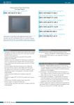
1
IPC Series
FLAT PANEL DISPLAY
For PanelLink
IPC-DT/L40S(PC)T
IPC-DT/H40X(PC)T
User’s Manual
CONTEC CO.,LTD.
Copyright
Copyright 2001 CONTEC CO., LTD. ALL RIGHTS RESERVED
No part of this document may be copied or reproduced in any form
by any means without prior written consent of CONTEC CO., LTD.
CONTEC CO., LTD. makes no commitment to update or keep
current the information contained in this document.
The information in this document is subject to change without
notice.
All relevant issues have been considered in the preparation of this
document. Should you notice an omission or any questionable
item in this document, please feel free to notify
CONTEC CO., LTD.
Regardless of the foregoing statement, CONTEC assumes no
responsibility for any errors that may appear in this document or for
results obtained by the user as a result of using this product.
Trademarks
MS, Microsoft, Windows, Windows NT and MS-DOS are
trademarks of Microsoft Corporation. Other brand and product
names are trademarks of their respective holder.
User’s Manual
i
Table of Contents
Copyright ........................................................................... i
Trademarks........................................................................ i
Table of Contents.............................................................. ii
1.Introduction.......................................................................1
Features........................................................................ 1
Limited One-Year Warranty ........................................ 2
How to Obtain Service ................................................. 2
Liability ........................................................................ 2
Handling Precautions .................................................. 3
2.Specifications.....................................................................7
Function Specifications .................................................... 7
General Specifications ..................................................... 8
Optical Display Specifications ......................................... 9
3.Outside Dimensions and Part Names ............................11
Outside Dimensions ........................................................11
Part Names ..................................................................... 14
4.Setting the Display .........................................................15
Setting the DIP switch ................................................... 15
Specifications of Remote Control Cable Connector ...... 16
Connector application example ................................. 16
5.Installation Procedure ....................................................17
6.Connection to the Host Computer and Power Supply ...19
Setting up the Host Computer....................................... 19
Connection Example ...................................................... 23
Power Supply.................................................................. 24
Panel Link Connector Specifications ............................ 25
7.Touch Panel .....................................................................27
8.Options ............................................................................29
ii
User’s Manual
1. Introduction
1. Introduction
The IPC-DT/L40S(PC)T and IPC-DT/H40X(PC)T are TFT color
liquid crystal displays (LCDs) to be used with host computers such
as the CONTEC IPC Series and SBCs (single-board computers).
Features
- Full-bright, wide-angle-of-visibility type of liquid crystals
capable of displaying up to 262,144 colors
- Touch panel enables mouse-style keyboard-less operation.
- Panel Link Interface allowing a cable of up to 5 m in length to be
used
- Thin panel unit has a mounting depth of only 38mm (when input
directly to 5VDC terminal)
- Back-mounted, dedicated power supply unit [IPC-POA100D]
available as an option, enabling the LCD to be used with an AC
power supply
- Equipped with a connector for remote control to get the full
benefit of the LCD
- Front structure with IP65-compliant ingress protection
* For the host computer to be used with the display or its options,
contact your local CONTEC branch or sales office.
User’s Manual
1
1. Introduction
Limited One-Year Warranty
CONTEC Products are warranted by CONTEC CO., LTD. to be
free from defects in material and workmanship for up to one year
from the date of purchase by the original purchaser.
Repair will be free of charge only when this device is returned
freight prepaid with a copy of the original invoice and a Return
Merchandise Authorization to the distributor or the CONTEC group
office, from which it was purchased.
This warranty is not applicable for scratches or normal wear, but
only for the electronic circuitry and original products. The
warranty is not applicable if the device has been tampered with or
damaged through abuse, mistreatment, neglect, or unreasonable use,
or if the original invoice is not included, in which case repairs will
be considered beyond the warranty policy.
How to Obtain Service
For replacement or repair, return the device freight prepaid, with a
copy of the original invoice. Please obtain a Return Merchandise
Authorization Number (RMA) from the CONTEC group office
where you purchased before returning any product.
* No product will be accepted by CONTEC group without the
RMA number.
Liability
The obligation of the warrantor is solely to repair or replace the product.
In no event will the warrantor be liable for any incidental or
consequential damages due to such defect or consequences that arise
from inexperienced usage, misuse, or malfunction of this device.
2
User’s Manual
1. Introduction
Handling Precautions
Take the following precautions when handling this board.
- This display is made of the precise electric parts, so do not use or
store it in the vicinity of impulse or vibration.
- Do not use or store the product in a location exposed to extremely
high or low temperature or susceptible to rapid temperature
changes.
Example:
- Exposure to direct sun
- In the vicinity of a heat source
- There are switches and jumpers on the board that need to be set in
advance. Be sure to check these before installing to the
expansion slot. Only set the switches and jumpers on the board
to the specified settings. Otherwise, the product may cause a
failure.
- Do not use the product in extremely humid or dusty locations.
- This product is not intended for use in aerospace, space, nuclear
power, medical equipment, or other applications that require a
very high level of reliability. Do not use the product in such
applications.
- If you utilize this product in such usages where high reliability
and safety are required as on the trains, vessels, automotives or
crime- or disaster-prevention devices, contact your retailer.
- Do not use touch panel key operations to initiate actions where
there is a risk of loss of life or serious injury. Ensure that the
system design can handle the case when a key is pressed by
mistake.
- Do not use any sharp-pointed object such as a mechanical pencil
to touch the touch panel. Doing so may scratch the touch panel,
resulting in malfunctions.
- Do not subject the touch panel to shock as doing so may break it.
- Do not modify the product. CONTEC will bear no
responsibility for any problems, etc., resulting from modifying
this product.
- Use the power supply intended for use with this unit whenever
possible. If using a power supply other than the intended power
supply, ensure that it satisfies the required voltage and maximum
current ratings.
- Never disconnect the display cable when the host computer is
turned on. To avoid damage to the display, turn off the computer
before inserting or disconnecting the display cable.
- In the event of failure or abnormality, contact your retailer.
User’s Manual
3
1. Introduction
- When the surface or frame of the touch panel has become dirty,
wipe it with neutral detergent. Do not wipe the touch panel with
thinner, alcohol, ammonia, or a strong chlorinated solvent. Use
a protective sheet (available as an option) if the touch panel is
used where it can easily collect dust and dirt.
- This display does not support the OS other than the following OS.
Windows 2000 Professional, Windows NT 4.0 Workstation,
Windows 98 Second Edition
- A characteristic of analog touch panels is that the detected
position may vary due to changes in the ambient environment
(temperature and humidity) and changes in resistance values over
time. In such cases, the touch panel should be recalibrated and
the calibration data updated.
- LCD display may have some pixels being dropped (bright and
black spots) below a certain threshold.
Note that this is not a failure or a defect.
- Regular maintenance is necessary for the backlight on the touch
panel and the display for the longevity parts.
Burn-in on TFT Display
- "Burn-in" may occur if the same display is retained for a long
time. Avoid this by periodically switching the display so that
the same display is not maintained for a long time.
* Burn-In---Phenomenon characterized by a TFT display as a result
of long-time display of the same screen where a
shadow-like trace persists because electric charge
remains in the LCD element even after the patterns are
changed.
- Component Life
(1) backlight--- The operating lifetime of the backlight is at least
seven years. (Brightness reduced to 50% of
original, assuming continuous operation at 25
degrees centigrade, Utilization rates 18 hours/one)
(2)Touch panel--- The operating lifetime of the touch panel is at
least 1 million touches (as tested by
mechanical touching under 300g of force at a
rate of two presses per second).
* CONTEC accepts your request for replacing each consumable in
the PANECON-PC as a request forrepair (at an additional cost).
Contact your local retailer or CONTEC sales office.
4
User’s Manual
1. Introduction
FCC PART 15 Class A Notice
NOTE
This equipment has been tested and found to comply with the limits for a Class A digital device,
pursuant to part 15 of the FCC Rules. These limits are designed to provide reasonable protection
against harmful interference when the equipment is operated in commercial environment.
This equipment generates, uses, and can radiate radio frequency energy and, if not installed and
used in accordance with the instruction manual, may cause harmful interference to radio
communications. Operation of this equipment in a residential area is likely to cause harmful
interference at his own expense.
WARNING TO USER
Change or modifications not expressly approved the manufacturer can void the user's authority to
operate this equipment.
User’s Manual
5
1. Introduction
6
User’s Manual
2. Specifications
2. Specifications
Function Specifications
Table 2.1.
Specification
Item
Assembly type
Function Specifications
IPC-DT/L40S(PC)T
IPC-DT/H40X(PC)T
Panel mounted
Screen size
12.1 inches
15 inches
Number of pixels
800 x 600 dots
1024 x 768 dots
Display type
TFT color LCD
Number of colors
262,144 colors
Brightness control
Provided by software and hardware
(Remote control cable connector on the back)
Backlight control
Provided by software and hardware
(Remote control cable connector on the back)
Cable length
2m or 5m (use the special-purpose display cable sold separately.)
LCD interface
20-pin MDR connector (Panel Link Interface used) *1
Power supply interface
4-pin nylon connector for +5 VDC power supply
(Input at 85 to 264 VAC is enabled by using the back-mounted, optional
power supply unit [IPC-POA100D].)
Touch Resolution
panel Detection method
4096 x 4096 (Emulated in 800 x 600)
4096 x 4096 (Emulated in 1024 x 768)
Resistive-layer analog method
Touch life expectancy The operating lifetime of the touch panel is at least 1 million touches
(as tested by mechanical touching under 300g of force at a rate of two presses
per second)
Touch panel interface 20-pin MDR connector on the back (shared with display signals)
Power consumption
*1 :
3.3A Max. at +5 VDC±5%
4.0A Max. at +5 VDC±5%
When used for output to the LCD, the CONTEC IPC or SBC series requires a converter such
as the LCD signal conversion unit [ADPLNK(PC)H] depending on the model of the host.
Check this out before purchase.
User’s Manual
7
2. Specifications
General Specifications
Table 2.2.
General Specifications
Specification
Condition
IPC-DT/L40S(PC)T
IPC-DT/H40X(PC)T
Environment
Ambient operating temperature
0 - 50°C
Ambient storage temperature
-10 - 60°C
Ambient humidity
10 - 90%RH (No condensation )
Floating dust
Normal
Corrosive gas
Noise
resistance
Vibration
resistance
None
Line noise
AC line: 2 kV, Signal line: 1 kV
(IEC1000-4-4Level3, EN61000-4-4Level3)
(Host: IPC-BX/M600(PCW), Power supply: IPC-POA100D)
Electrostatic
withstanding
voltages
Contact: 4 kV (IEC1000-4-2 Level 2, EN61000-4-2 Level 2)
Airborne: 8 kV (IEC1000-4-2 Level 3, EN61000-4-2 Level 3)
(Host: IPC-BX/M600(PCW), Power supply: IPC-POA100D)
Sweep durability
10 - 50 Hz/Single-side amplitude or 0.15 mm
50 - 500 Hz/2.0 G in the X/Y/Z directions for 23 minutes each
(Conforming to JIS C0040 and IEC68-2-6)
Fixed-vibration
durability
16.7 Hz/2 G in the X/Y/Z directions for 30 minutes each
(Conforming to JIS C0040 and IEC68-2-6)
Shock resistance
10 G in the X/Y/Z directions for 11 ms; Half-sine wave
(Conforming to JIS C0041 and IEC68-2-27)
Structure
Major dimensions (mm)
370(W) x 40.4(D) x 307(H)
428(W) x 40.4(D) x 336(H)
Panel cut dimensions (mm)
344±0.5(W) x 281±0.5(H)
(12 stud holes are required on
the periphery.)
398±0.5(W) x 306±0.5(H)
(12 stud holes are required on the
periphery.)
Weight
About 4.0 kg (*2)
About 5.0 kg (*2)
Ingress protection
*2:
8
Front part conforming to IP65
The weight includes neither cables nor the optional power supply.
User’s Manual
2. Specifications
Optical Display Specifications
Table 2.3.
Optical Display Specifications
Item
Specifications
Condition
IPC-DT/L40S(PC)T IPC-DT/H40X(PC)T
φ = 180°
Visual angle
(Up/Down)
φ = 0°
CR≥10
Visual angle
(Right/Left)
Surface brightness
50deg
60deg
φ = +90° monochrome
70deg
75deg
φ= -90°
70deg
75deg
Display in white
(at center) *1
50deg
70deg
Display in
2
350cd/m (Typ.)
250cd/m2 (Typ.)
*1 Surface brightness is a numerical value in a display simple substance. The brightness that let the
touch panel pass serves as about 77% of the above-mentioned numerical value.
Measurement direction
Z
( θ = 0o )
Left
( φ = -90o )
θ
Top
( φ = 180o )
X
φ
Module
Bottom
( φ = 0o )
Right
( φ = 90o )
Y
Figure 2.1. Viewing Range Definition
Note!
The above optical specification data shows optical characteristics
of the liquid crystal in the display; the data does not represent the
actual view on the display or its viewing angles.
User’s Manual
9
2. Specifications
10
User’s Manual
3. Outside Dimensions and Part Names
3. Outside Dimensions and Part Names
Outside Dimensions
IPC-DT/L40S(PC)T
4-M4 TAP
(Maximum tapping length : 7mm)
119
119
119
342
12-M4 STUD
38
370
2.4
13
98
251
100
98
89.75
98
279
307
99.75
100
[mm]
Figure 3.1. Outside Dimensions of Main Unit
(IPC-DT/L40S(PC)T)
IPC-DT/H40X(PC)T
12-M4 STUD
428
13
38
137
137
396
2.4
137
7
100
107
304
254
100
106
138
7
336
236.7
106
310.1
157.5
CONTEC
4-M4 TAP (Including the mate)
Maximum tapping length:4mm)
4-M4 TAP
(Maximum tapping
length:4mm)
302
4-M4 TAP (Including the mate)
Maximum tapping length:4mm)
[mm]
Figure 3.2. Outside Dimensions of Main Unit
(IPC-DT/H40X(PC)T)
User’s Manual
11
3. Outside Dimensions and Part Names
IPC-DT/L40S(PC)T with IPC-POA100D (power supply unit)
12-M4 STUD
119
342
58
38
119
2.4
13
370
307
67
98
98
279
98
119
280
17
(85)
48.5
140
[mm]
Figure 3.3. Dimensions of IPC-DT/L40S(PC)T with
IPC-POA100D
IPC-DT/H40X(PC)T with IPC-POA100D (power supply unit)
12-M4 STUD
137
396
137
13
58
38
2.4
428
17
67
106
336
107
304
106
137
113
167
(85)
21.5
167
[mm]
Figure 3.4. Dimensions of IPC-DT/H40X(PC)T with
IPC-POA100D
12
User’s Manual
3. Outside Dimensions and Part Names
45mm
20mm
Figure 3.5. Cable Bend Dimension
User’s Manual
13
3. Outside Dimensions and Part Names
Part Names
Touch panel over liquid crystals
Power LED
Panel Link connector
Remoto control cable connector
DIP-SW
5VDC power supply connecotr
Figure 3.6. Part Names (IPC-DT/L40S(PC)T and
IPC-DT/H40X(PC)T)
14
User’s Manual
4. Setting the Display
4. Setting the Display
Be sure to check the following settings before using the display.
Setting the DIP switch
The display has a DIP switch (an array of built-in switches) on the
back. For normal use of the display, leave all of the built-in
switches at the OFF positions (as factory-set). The table below
shows the functions of the built-in switches.
1
2
3
4
ON
Figure 4.1. DIP Switch
Table 4.1.
No.
1
DIP Switch Settings
ON/OFF setting
Function
OFF (Factory setting) Enable the display built-in buzzer to sound upon a touch on the
touch panel.
(The buzzer ON/OFF setting can also be controlled
by driver software.)
ON
Disable the display built-in buzzer from sounding upon a touch on
the touch panel.
(The buzzer ON/OFF setting can also be
controlled by driver software.)
2
OFF (Factory setting) Use a host other than below.
ON
Use an SBC board PC-686C(PC)H-LV , -LVS
IPC-BX/M620(PCW) Series, or IPC-BX/M630(PCI) Series.
3
OFF (Factory setting) No function
4
OFF (Factory setting) No function
ON
ON
No function
No function
Notes!
- The buzzer is disabled by setting the DIP switch (built-in switch
No. 1 to ON).
- Set built-in switch No. 2 depending on the host product to be
used with the display.
User’s Manual
15
4. Setting the Display
Specifications of Remote Control Cable
Connector
The display has the remote control cable connector on the back.
Given below are the pin assignments on the connector and an
example of using it.
Table 4.2.
Remote Control Cable Connector
Connector type
Model
Cable connector (Side type)
S6B-XH-A(LF)(SN)(mfd. by JST)
1
Pin No.
1
2
3
4
5
6
2
3
4
5
6
Signal name
Brightness UP
GND
Brightness DOWN
GND
Backlight ON/OFF *1
GND
*1 : The backlight remains off while the backlight ON/OFF signal has the GND level.
Connector application example
Pushbutton switches (SW1, SW2)
SW1
1
2
3
4
5
6
SW2
SW3
ON/OFF switch (SW3)
Connector model: XHP-6 (JST)
Figure 4.2. Connector Application Example
Notes!
- Applying a GND-level voltage to the brightness UP or DOWN
signal increases or decreases the brightness.
- The brightness remains unchanged if the two signals (brightness
UP and DOWN signals) are input at the same time.
- The remote control cable is not bundled with this product.
16
User’s Manual
5. Installation Procedure
5. Installation Procedure
(1) Cut a panel in the following dimensions for installing the
display.
The four corners of the solid-line rectangle define the panel cut
dimensions. The holes (12) on dashed lines represent stud
holes.
119
344
119
98
98
281
98
119
[mm]
12 φ 05
Figure 5.1. Display Mounting Position
(IPC-DT/L40S(PC)T)
137
398
137
106
107
306
106
137
12 φ 05
[mm]
Figure 5.2. Display Mounting Position
(IPC-DT/H40X(PC)T)
User’s Manual
17
5. Installation Procedure
(2) Insert the supplied gasket between the panel and the display,
then fasten them together with M4 nuts as shown below.
Display
Gasket
Panel
Figure 5.3. Assembling Method
Note!
The panel must be up to 10 mm in thickness.
18
User’s Manual
6. Connection to the Host Computer and Power Supply
6. Connection to the Host Computer and Power
Supply
If using IPC or SBC products other than those listed here, refer to
their respective manuals for details of the settings.
Setting up the Host Computer
The IPC-DT/L40S(PC)T and IPC-DT/H40X(PC)T can be used with
host computers such as the CONTEC IPC Series and SBCs (singleboard computers). The host computer to be connected must be set
up correctly for using the display. Set the IPC-DT/L40S(PC)T to
SVGA (800 x 600) or the IPC-DT/H40X(PC)T to XGA (1024 x
768).
Set the LCD type as follows depending on the host computer to be
used.
PC-686BX(PC)-LV
To use this SBC board with the display, set the on-board switch
(U2) as shown below.
12.1-inch IPC-DT/L40S(PC)T
15-inch IPC-DT/H40X(PC)T
U2
U2
ON
1
ON
2
3
4
5
6
7
8
1
2
3
4
5
6
7
Set all bits to OFF.
Set only 1 to ON
(TFT color LCD in 800 x 600)
(TFT color LCD in 1024 x 768)
8
Figure 6.1. U2 Switch Settings
Note!
Use this board along with the ISA bus type of LCD signal
conversion board [ADPLNK(PC)].
User’s Manual
19
6. Connection to the Host Computer and Power Supply
PC-686C(PC)-LV or -LVS
Since this SBC board is Plug and Play compliant, there is no need
to set up the host computer.
Instead, set the DIP built-in switch No. 2 to ON.
(See Chapter 4.)
Note!
Use this board along with the 26/20-pin conversion cable
[IPC-PL2620-002/C].
PC-686E(PC)-LV
To use this SBC board with the display, set the on-board rotary
switch as shown below.
Table 6.1.
PC-686E(PC)-LV
12.1-inch IPC-DT/L40S(PC)T
15-inch IPC-DT/H40X(PC)T
Setting No. = 0 (TFT color LCD in 800 x 600)
Setting No. = 1 (TFT color LCD in 1024 x 768)
Note!
Use this board along with the ISA bus type of LCD signal
conversion board [ADPLNK(PC)].
20
User’s Manual
6. Connection to the Host Computer and Power Supply
PC-586U(PC)-LV or -LVS
To use this SBC board with the display, set the on-board switch (S2)
as shown below.
12.1-inch IPC-DT/L40S(PC)T
15-inch IPC-DT/H40X(PC)T
S2
S2
ON
1
ON
2
3
4
1
2
3
4
Set all bits to OFF.
Set only 1 to ON.
(TFT color LCD in 800 x 600)
(TFT color LCD in 1024 x 768)
Figure 6.2. S2 Switch Settings
Note!
Use this board along with the LCD signal conversion mini-board
[EXLCD68] and the ISA bus type of LCD signal conversion board
[ADPLNK(PC)].
PC-586HU(PC)-LV
To use this SBC board with the display, set the on-board jumper
(JP8) as shown below.
12.1-inch IPC-DT/L40S(PC)T
15-inch IPC-DT/H40X(PC)T
JP8
JP8
7
8
1
2
7
8
1
2
Leave all pins unconnected.
Connect only the 1-2 pins.
(TFT color LCD in 800 x 600)
(TFT color LCD in 1024 x 768)
Figure 6.3. JP8 Setting
Note!
Use this board along with the ISA bus type of LCD signal
conversion board [ADPLNK(PC)].
User’s Manual
21
6. Connection to the Host Computer and Power Supply
IPC-BX/M600(PCW)
To use this box computer with the display, set the on-board switch
(S1) as shown below.
12.1-inch IPC-DT/L40S(PC)T
15-inch IPC-DT/H40X(PC)T
S1
S1
ON
1
ON
2
3
4
5
6
7
8
1
2
3
4
5
6
7
8
Set 5, 6, and 7 to ON.
Set 6, 7, and 8 to ON.
(TFT color LCD in 800 x 600)
(TFT color LCD in 1024 x 768)
Figure 6.4. S1 Switch Settings
22
User’s Manual
6. Connection to the Host Computer and Power Supply
Connection Example
Illustrated below is an example of connecting the display to the box
computer [IPC-BX/M600(PCW)C, CP].
IPC-BX/M600(PCW)C, CP
Panel Link cable(Option)
[IPC-PL2020-020] (2m)
[IPC-PL2020-050] (5m)
Display
-IPC-DT/L40S(PC)T
-IPC-DT/H40X(PC)T
5VDC
Figure 6.5. System Configuration
User’s Manual
23
6. Connection to the Host Computer and Power Supply
Power Supply
The display operates at 5VDC. For the supply voltage, use a
power supply satisfying at least the capacity defined in the
Specifications.
Turn the 5VDC supply On in accordance with the following
sequence.
1 - 50ms
(Rise time to 4.75V)
+5V
0V
Figure 6.6.
Power On Sequence
Table 6.2.
Power Supply Connector
Connector type 5VDC input connector
Model
B4PS-VH(LF)(SN)(mfd. by JST)
1
2
3
4
Pin No.
Signal name
1
GND
2
GND
3
+5V
4
+5V
Applicable power cable connector
Housing: VHR-4N (manufactured by JST)
Contact: SVH-21T-1.1(LF)(SN)(AWG22 - 18)
(manufactured by JST)
Although the display operates at 5VDC, the dedicated 5VDC output
AC power supply [IPC-POA100D] is available as an option so that
the display can be used with an AC power supply.
24
User’s Manual
6. Connection to the Host Computer and Power Supply
Panel Link Connector Specifications
The display is equipped with the Panel Link Interface. The table
below lists the pin specifications of the Panel Link connector on the
back of the display.
Table 6.3.
Connector type
Model
Pin No.
User’s Manual
Panel Link Connector
Panel Link Interface connector(CN3)
N10220-5DG3 PL(mfd. by 3M)
A10
A1
B10
B1
Signal name
Pin No.
Signal name
A1
TX0-
B1
TXC-
A2
TX0+
B2
TXC+
A3
TX0 SHIELD
B3
TXC SHIELD
A4
TX2 SHIELD
B4
TX1 SHIELD
A5
TX2-
B5
TX1-
A6
TX2+
B6
TX1+
A7
DDC/SCL
B7
N.C.
A8
DDC/SDA
B8
SENS
A9
TXD(HOST)
B9
N.C.
A10
RXD(HOST)
B10
GND
25
6. Connection to the Host Computer and Power Supply
26
User’s Manual
7. Touch Panel
7. Touch Panel
The IPC-DT/L40S(PC)T) and IPC-DT/H40X(PC)T is equipped
with a quick response touch panel which enables keyboard-less,
mouse-less operations using the serial interface (RS-232C) with the
host computer.
Touch panel
Host PC
CPU
Touch panel controller
Serial controller
NS16550 compatible
INT
Touch panel
8bit CPU
Serial
communication
Figure 7.1. Touch Panel and Block Diagram
Data input at the touch panel is processed by the touch panel
controller and passed to the host PC via the serial port on the CPU
in the controller.
Before the touch panel can be used, touch panel driver software
(TPBK(PC)S) must be installed. Note that the driver software is
not bundled with this product. Use the one (to be) downloadable
from the CONTEC’s home page or the one included on the driver
software CD-ROM (IPC-SLIB-01) available as an option
(separately priced). The CD-ROM need to be purchased
separately.
The touch panel driver supports Windows 95, 98, NT4.0, and 2000.
For further details, refer to the READ_ME file for each driver.
Communication format
- Baud rate
9600
- Data length
8 bits
- Parity
Even parity
- Stop bit
1 bit
User’s Manual
27
7. Touch Panel
28
User’s Manual
8. Options
8. Options
Double-sided screen protective sheets
- IPC-CV12
: (12.1-inch screen protective sheets: 10
sheets)
- IPC-CV15
: (15-inch screen protective sheets: 10 sheets)
Driver
- IPC-SLIB-01
: Driver & Utility Soft Set(CD-ROM version)
Power unit
- IPC-POA100D
: 100V to 240VAC power unit
- IPC-POD24/5
: 24VDC input power unit
LCD I/F board
- ADPLNK(PC)H : Panel Link I/F board for SBC(ISA bus)
Optional cables
- IPC-PL2020-020 : Panel link cable (2 m)
- IPC-PL2020-050 : Panel link cable (5 m)
- IPC-DVIPL-020 : DVI - panel link conversion display cable
(2m)
- IPC-DVIPL-050 : DVI - panel link conversion display cable
(5m)
User’s Manual
29
IPC-DT/L40S(PC)T
IPC-DT/H40X(PC)T
User’s Manual
IPC-DT/x40x-HMU
CONTEC CO.,LTD.
August 2007 Edition
3-9-31, Himesato, Nishiyodogawa-ku, Osaka 555-0025, Japan
Japanese http://www.contec.co.jp/
English
http://www.contec.com/
Chinese
http://www.contec.com.cn/
No part of this document may be copied or reproduced in any form by any means without prior written
consent of CONTEC CO., LTD.
[08012007]
[02222001]
Management No.
A-46-452
[08012007_rev7]
Parts No.
LZS9912