1
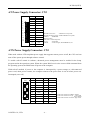
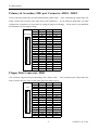
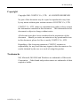
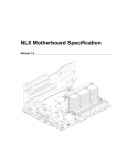
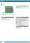
NLX Bus Backplane Board
PC-BP4/3(NLX) User's Guide
Package Contents
- The PC-BP4/3(NLX) Back Plane Board...1
- User’s Manual (this booklet)...1
Specifications
- 8-Slot NLX Backplane
1 x NLX, 3 x PCI,1 x PCI/ISA,
1 x ISA , 1 x ISA(8bit, for ADPLNK(PC)(CONTEC Product))
- 6-Layes PCB With ATX and AT Power Connectors
- 5.LED Power indicators :
+5V, -5V, +12,-12V and +3.3V
- 2 x FAN connectors
- 2 x IDE port connector
- 1 x FDD port connector
- 2 x USB port
- 1 x Front Panel Connector
- 1 x External Battery connector
Item
Number of slots
Specification
1 x NLX bus slot
3 x PCI bus slot
1 x PCI/ISA bus slot
1 x ISA bus slot
1 x ISA bus slot (for ADPLNK(PC))
Operating conditions
0~50°C,10~85% (No condensation allowed)
Storage conditions
0~70°C
Major dimensions (mm)
220.50(L) x 210.0(W) x 17.0(H) (Board + Bus slot)
Weight
370g
-1-
PC-BP4/3(NLX)
Board Dimension
Notes!
-
ISA2, 3 are not mount.
-
ISA1 is for ADPLNK(PC) (CONTEC Products).
-
ISA4, PCI4 are PCI/ISA shared.
CONTEC CO., LTD.
-2-
PC-BP4/3(NLX)
Pin Assignment Connectors
Connector
Description
NLX
NLX BUS connector
PCI1, PCI2, PCI3, PCI4
32-bit PCI BUS connector
ISA1
8-bit ISA BUS connector
ISA4, ISA5
16-bit ISA BUS connector
VBAT
Ext. battery connector
FAN2, FAN3
Power connector for CPU fan use
CN2
AT power supply connector
CN3
ATX power control connector
IDE1, IDE2
IDE device connectors
FDD
Floppy Disk Device connector
CN8
Front Panel connector
USB connector
Universal Serial Bus connector
External Battery Connector: VBAT
It is a 2 Pin connector used for external battery.
An external battery powers the real-time clock and
CMOS memory.
VBAT
2
1
PIN No.
1
2
Function
GND
Ext_bat
Housing : XHP-2(JST)
Contact : SXH-001-P0.6(JST)
CPU FAN Connector: FAN2 / FAN3
FAN2 and FAN3 are 3-pins box-header for the CPU cooling fan power connector.
12V fan.
The fan must be a
Pin 3 is for Fan speed sensor input.
FAN2/FAN3 PIN No.
1
2
1 2 3
3
Function
GND
POWER
FAN
Connector type for Cable
Housing: 5102-03 (molex)
Contact: 5103 (molex)
-3-
CONTEC CO., LTD.
PC-BP4/3(NLX)
AT Power Supply Connector: CN2
1
2
3
4
5
6
7
8
9
10
11
12
PIN No.
Function
1
Power Good
2
+5V
3
+12V
4
-12V
5
GND
6
GND
7
GND
8
GND
9
-5V
10
+5V
11
+5V
12
+5V
Suitable Connector
: GTC6P-1(correspond)
Suitable Socket Contact : PCK18-2TR9(correspond)
Maker
: BURNDY
Option Cables
(one side is solder disposal)
Type
: PCA-6P2
Model
: Cable length, 36cm(AWG#18), two
ATX Power Supply Connector: CN3
When used with an ATX-compliant power supply that supports remote power on/off, the CPU card can
turn off the system power through software control.
To enable soft-off control in software, advanced power management must be enabled in the Setup
program and in the operation system. When the system BIOS receives the correct APM command from
the operating system, the BIOS turns off power to the computer.
With soft-off enabled, if power to the computer is interrupted by a power outage or a disconnected
power cord, when power resumes, the computer returns to the power state it was in before power was
interrupted (on or off).
CN2
11
20
CONTEC CO., LTD.
1
10
PIN No.
Function
PIN No.
Function
11
+3.3V
1
+3.3V
12
-12V
2
+3.3V
13
GND
3
GND
14
PON
4
+5V
15
GND
5
GND
16
GND
6
+5V
17
GND
7
GND
18
-5V
8
Power Good
19
+5V
9
PWRSB
20
+5V
10
+12V
-4-
Cable side Connector Maker : Molex
Cable side Connector Type : 5557-20R
(39-01-2200)
Cable side Connector Contact Type: 5556
PC-BP4/3(NLX)
Primary & Secondary IDE port Connector: IDE1 / IDE2
These connectors support the provided IDE hard disk ribbon cable. After connecting the single end to the
board, connect the two plugs at the other end to your hard disk(s). If you install two hard disks, you must
configure the second drive to Slave mode by setting its jumper accordingly. Please refer to your hard disk
documentation for the jumper setting.
PIN No.
1
3
IDE1/IDE2
5
1
2
7
9
11
13
15
17
19
21
23
25
27
29
31
39
40
33
35
37
39
Function
RESET
D7
D6
D5
D4
D3
D2
D1
D0
GND
DREQ
IOW
IOR
IORDY
DACK
IRQ
A1
A0
PIN No.
2
4
6
8
10
12
14
16
18
20
22
24
26
28
30
32
34
36
Function
GND
D8
D9
D10
D11
D12
D13
D14
D15
N.C.
GND
GND
GND
ALE
GND
IOCS16
PDIAG
A2
CS0
HD ACT
38
40
CS1
GND
Floppy Disk Connector: FDD
This connector supports the provided floppy drive ribbon cable.
After connecting the single and to the
board, connect the two plugs on the other end to the floppy drives.
PIN No.
1
3
FDD
5
1
2
7
9
11
13
15
17
19
21
23
25
27
33
34
29
31
33
Function
GND
GND
GND
GND
GND
GND
GND
GND
GND
GND
GND
GND
GND
GND
GND
GND
GND
PIN No.
2
4
6
8
10
12
14
16
18
20
22
24
26
28
30
32
34
-5-
Function
RWC
N.C.
N.C.
INDEX
DS0
DS1
DS2
MOT ON
DIR
STEP
WD
WG
TRCK 0
WP
RD
SIDE 1
DSK CHG
CONTEC CO., LTD.
PC-BP4/3(NLX)
Front Panel Connector: CN8
This header can be connected to a front panel power switch.
The front panel connector includes headers for these I/O connections:
Power switch
Power LED
This header can be connected to an LED that will light when the computer is powered on.
KEY LOCK
Key lock allows you to disable the keyboard for security purposes.
You can connect the key lock to
this pin.
Hard drive activity LED
This header can be connected to an LED to provide a visual indicator that data is being read from or
written to an IDE hard drive.
For the LED to function properly.
The IDE drive must be connected to
the onboard IDE controller.
Speaker
A speaker can be installed on the PC-686BX(NLX)-LV as a manufacturing option.
The speaker is
enabled by a jumper on pins 13, 19 of the front panel connector.
CN8
1
19
PIN No. Function PIN No. Function
STROBE
HD LED+
2
1
RST SW
GND
4
3
2
N.C.
N.C.
6
5
PWR ON
GND
8
7
N.C.
GND
10
9
N.C.
PLED+
12
11
+5V
N.C.
14
13
N.C.
GND
16
15
20
BUZZER
KB LOCK
18
17
SPEAKER
GND
20
19
Suitable Connector : PS-20SEND4P1-1C(correspond)
Maker : JAE
CONTEC CO., LTD.
HDD-activeIndicator LED
Reset Switch
Power Switch
for ATX
Power LED
External Speaker
(ex.8Ω 0.25W)
-6-
KEY LOCK
PC-BP4/3(NLX)
USB Connector: USB
The Universal Serial Bus (USB) that allows plug and play computer peripherals such as keyboard,
mouse, joystick, scanner, printer, modem/ISDN, CD-ROM and floppy disk drive to be automatically
detected when they are attached physically without having to install drivers or reboot.
The USB connectors allow any of several USB devices to be attached to the computer.
device driver for USB devices is managed by the operating system.
Typically, the
However, because keyboard and
mouse support may be needed in the Setup program before the operating system boots, the BIOS
supports USB keyboards and mice.
The CPU card has two USB ports; one USB peripheral can be connected to each port.
two USB devices, an external hub can be connected to either port.
implemented with stacked back panel connectors.
For more than
The two USB ports are
The CPU card fully supports the universal host
controller interface (UHCI) and uses UHCI-compatible software drivers.
USB features includes:
- Self-identifying peripherals that can be plugged in while the computer is running
- Automatic mapping of function to driver and configuration
- Support for isochronous and asynchronous transfer types over the same set of wires
- Support for up to 127 physical devices
- Guaranteed bandwidth and low latencies appropriate for telephony, audio and other applications
- Error-handling and fault-recovery mechanisms built into the protocol
Notes!
-
When using PC-686BX(NLX) Series (CONTEC Products), please use the USB
connector on the CPU Board.
-
Computer systems that have an unshielded cable attached to a USB port may not
meet FCC Class B requirements, even if no device or a low-speed USB device is
attached to the cable. Use shielded cable that meets the requirements for fullspeed devices.
USB
1
9
PIN No.
1
2
3
5
7
10
9
Function
Vcc
USBP0USBP0+
USBG
GND
PIN No.
2
4
6
8
10
-7-
Function
Vcc
USBP1USBP1+
USBG
GND
CONTEC CO., LTD.
PC-BP4/3(NLX)
Copyright
Copyright 2001 CONTEC Co., LTD. ALL RIGHTS RESERVED
No part of this document may be copied or reproduced in any form
by any means without prior written consent of CONTEC Co., LTD.
CONTEC Co., LTD. makes no commitment to update or keep current
the information contained in this document. The information in this
document is subject to change without notice.
All relevant issues have been considered in the preparation of this
document. Should you notice an omission or any questionable item
in this document, please feel free to notify CONTEC Co., LTD.
Regardless of the foregoing statement, CONTEC assumes no
responsibility for any errors that may appear in this document nor for
results obtained by the user as a result of using this product.
Trademarks
MS, Microsoft, MS-DOS and Windows are trademarks of Microsoft
Corporation. Other brand and product names are trademarks of their
respective holder.
CONTEC CO., LTD.
-8-
PC-BP4/3(NLX)
Limited One-Year Warranty
CONTEC IPC Series are warranted by CONTEC Co., LTD to be free
from defects in material and workmanship for up to one year from the
date of purchase by the original purchaser.
Repair will be free of charge only when this device is returned freight
prepaid with a copy of the original invoice and a Return Merchandise
Authorization to the distributor or the CONTEC group office, from
which it was purchased.
This warranty is not applicable for scratches or normal wear, but only
for the electronic circuitry and original boards. The warranty is not
applicable if the device has been tampered with or damaged through
abuse, mistreatment, neglect, or unreasonable use, or if the original
invoice is not included, in which case repairs will be considered
beyond the warranty policy.
How to Obtain Service
For replacement or repair, return the device freight prepaid, with a
copy of the original invoice. Please obtain a Return Merchandise
Authorization Number (RMA) from the CONTEC group office where
you purchased before returning any product.
*No product will be accepted by CONTEC group without the
RMA number.
Liability
The obligation of the warrantor is solely to repair or replace the
product. In no event will the warrantor be liable for any incidental
or consequential damages due to such defect or consequences that
arise from inexperienced usage, misuse, or malfunction of this
device.
-9-
CONTEC CO., LTD.
CONTEC Group
JAPAN
: Headquarters
CONTEC Co., LTD.
3-9-31, Himesato, Nishiyodogawa-ku, Osaka 555-0025, Japan
Tel
: +81 (6) 6477-5219
Fax : +81 (6) 6477-1692
E-mail : [email protected]
U.S.A.
: CONTEC MICROELECTRONICS U.S.A. INC.
744 South Hillview Drive, Milpitas, CA 95035 U.S.A.
Tel
: +1 (408) 719-8200
Fax : +1 (408) 719-6750
E-mail : [email protected]
EUROPE
: CONTEC MICROELECTRONICS EUROPE B.V.
Binnenweg 4, 2132 CT, Hoofddorp, The Netherlands
Tel
: +31 (23) 567-3030
Fax : +31 (23) 567-3035
E-mail : [email protected]
KOREA
: HYOJIN CONTEC Co., LTD.
Ki-im Bldg. #399, Shindolim-Dong, Kuro-ku, Seoul, Korea
Tel
: +82 (2) 2636-4277/8
Fax : +82 (2) 2636-4279
E-mail : [email protected]
CHINA
:
INTERNATIONAL CONTEC TECHNOLOGY CO., LTD.
B-8F, Hua Tong Building, No. B19, Che Gong Zhuang West Road,
Hai Dian District, Beijing 100044, China
Tel
: +86(10)8801-8228
Fax : +86 (10)8801-8209
E-mail : [email protected]
SHANGHAI CONTEC MICROELECTRONICS CORP.
No. 481 Gui Ping Road, Cao He Jing Hi-Tech Park Shanghai, 200233, China
Tel
: +86 (21) 6485-1907
Fax : +86 (21) 6485-0330
E-mail : [email protected]
SHENYANG CONTEC MICROELECTRONICS Co., LTD.
No. 169, Qingnian Street, Shenhe District, Shenyang 110015, China
Tel
: +86 (24) 2392-9771
Fax : +86 (24) 2392-9773
TAIWAN
: MACROMATE CORP.
8F, Universal Center, No.179, Ta-Tung Rd., Sec.1 Hsi-Chih, Taipei Hsien, Taiwan,
R.O.C
Tel
: +886 (2) 2647-9353
Fax : +886 (2) 2647-9373
E-mail : [email protected]
A-46-484
LZU7051
021030 [010523]