1
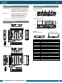
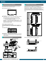
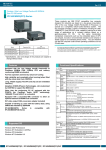
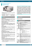
Ver.1.12
Fanless, Ultra Low Voltage Cerelon 400MHz
Box-PC 620 series
IPC-BX/M620(PCW)C Series
These products are IBM PC/AT compatible, box computer
designed for industrial use based on a low-power-consumption
CPU of the Ultra Low Voltage Intel(R) Celeron(R) Processor
400MHz, to operate as a completely nature-cooled (fanless)
system. The box computer provides a variety of interfaces
including the USB, 100BASE-TX, and RS-232C ports, capable of
serving for a wide range of applications as a compact platform
based on a general-purpose PC OS. As this series incorporates
handpicked components such as the embedded types of CPU
and chipset, it excels in environmental resistance and remains in
stable supply for an extended period of time. You can therefore
use the box computer under severe operating conditions such as
FA with ease.
The below : IPC-BX/M620(PCW)C
The above : IPC-BX/M620(PCW)CP
Other than these products, there is a model with 4 expansion slots / without Write
filter function. For more details on this, please contact your retailer.
Model
Expansion Slot
-
IPC-BX/M620(PCW)C
IPC-BX/M620(PCW)CP
*
2.5 inches hard disk drive (HDD) of our company has not guaranteed use by continuation
and continuation power for 24 hours. When it is used by continuation operation and
continuation power a life fails extremely. In the case of a 24-hours operation system, use of
our company silicon disk drive (SDD) is recommended.
OS
(storage device)
-
Shared PCI/ISA slot x 2
* Specifications, color and design of the products are subject to
change without notice.
Features
Equipped with the Ultra Low Voltage Intel(R) Celeron(R)
Processor 400MHz (FSB 100MHz) CPU and memory
conforming 256MB as standard
Fan-less operation achieved by natural air-cooling
High reliability and completely silent running (when fitted
with the silicon disk from CONTEC)
Long, reliable supply (The CPU and chip set are embedded
versions.)
Adoption of BIOS (Phoenix Technologies, Ltd.) customized
by CONTEC to support the BIOS level
Other than the conforming PC I/F, equipped with the
PCMCIA (for CardBus), Audio (AC97 conforming),
100BASE-TX and RAS I/F as a standard
Equipped with a secondary-IDE connector to allow an
optional external CD-ROM to be connected
Capable of starting up, even with the battery dead, using
CMOS data retained by EEPROM
Front part is the ingress protection for IP65 performance
Supported OS
Windows 2000 Professional
Windows NT Workstation 4.0(SP6a)
Windows XP Embedded
Windows NT Embedded 4.0
IPC-BX/M620(PCW)C, IPC-BX/M620(PCW)CP
Functional Specifications
<1/2>
Model
CPU
Chip set
Memory L2 Cache
Main
memory
BIOS
ROM
Video
Controller
Video
RAM
Video
BIOS
Display I/F
Audio
IPC-BX/M620(PCW)C
IPC-BX/M620(PCW)CP
Ultra Low Voltage Intel(R) Celeron(R) Processor, FSB100MHz
Intel(R) 815E
256KB
256 MB standard *1 / Max. 256MB (3.3V 144pin SO-DIMM PC100
Socket x 2)
128KB E0000H - FFFFFH (Phoenix)
Intel 815E (Built into the controller)
Main memory shared
48KB (C0000H - CBFFFF)
DVI-I 29pin *2
AC97 compliant
LINE IN: φ3.5 Stereo mini jack
Full-scale input level 1.3Vrms(Typ.)
LINE OUT: φ3.5 Stereo mini jack
Full-scale input level 1.0Vrms(Typ.)
MIC UN: φ3.5 monaural mini jack
Full-scale input level 1.3Vrms(Typ.)
FDD I/F
Equipped with a dedicated 26pin, half-pitch connector: 2 modes
(Optional FDD: PC-FDD25BH)
IDE
Primary
Ultra DMA/100
HDD
2.5 inch IDE HDD or silicon disk drive: 1 internal unit
I/F
(One more unit can be added. Either of the two must be a silicon disk
drive.)
Secondary Equipped with a dedicated 40pin, half-pitch connector
(for connection of an optional CD-ROM) (right surface)
Serial I/F
RS-232C(general-purpose): 2ch (SERIAL PORT1,2) 9pin, D-SUB
connector
RS-232C(touch panel): 1ch (SERIAL PORT3) [inside the DVI connector]
*3 *4
RS-422/485(general-purpose): 1ch (SERIAL PORT4) [inside the RAS
connector] *4
Parallel I/F *4
Bi-directional, Centronics-compliant, 25pin D-SUB connector
LAN
I/F
Ethernet 100BASE-TX/10BASE-T RJ-45 connector
Controller Intel ICH2 integrated
PC card slot
PCMCIA Type I, II x 2 or III x 1 (Startup from ATA card not allowed)
CardBus correspondence
USB I/F
2ch (USB 1.1)
Keyboard I/F
PS/2 type keyboard -compatible (6pin MINI DIN connector)
Mouse I/F
PS/2-type mouse-compatible (6pin MINI DIN connector)
General-purpose
3 opto-isolated inputs and outputs
I/O *4
(However, one output also serves as an external WDT output and one
input also serves as remote reset. They become available when
switched.)
RAS function *4
WDT: 1sec - 255sec (RESET or external output is allowed at time
expiration)
Remote reset: External input signal
1
Ver.1.12
<2/2>
Floppy disk unit
Model
IPC-BX/M620(PCW)C
Expansion board slot None
IPC-BX/M620(PCW)CP
PCI/ISA shared slot x 2 *5,
Installable board length
: 240mm (Max.)
Lithium backup battery life: 10 years or more
Automatically switched between 85 - 132 VAC and 170 - 265 VAC (47 - 63
Hz)
50VA (Max.)
90VA (Max.)
RTC/CMOS
Power Input supply
supply voltage
Current
consumption
Expansion
None
+5V: 2A(1A x 2 Slot),
board
-5V: Not supplied,
power-supply
+12V: 0.5A, -12V: 80mA
capacity
Physical dimensions
262(W) x 262(D) x 55(H)
262(W) x 262(D) x 115(H)
(mm)
Weight
Approx. 3.3kg
Approx. 4.2kg
*1 A 256 MB memory module is plugged in one socket.
*2 The interface can connect the PC to a CONTEC Panel Link input type display (using an
optional cable) or an ordinary analog RGB input display (using the bundled DVI-analog
RGB adapter).
*3 The interface is used for the CONTEC Panel Link or touch panel type display.
*4 Serial ports 3 and 4 can be used as general-purpose RS-232C ports by replacing the
bracket(Bundled). In that case, the touch panel, RAS functions (WDT time-out output
and remote reset input), RS-422/485, general-purpose inputs, and parallel interfaces are
disabled.
*5 The following signals cannot be used on ISA bus slots.
-5V, IOCHK, REFRESH, MASTER
The PCI bus slots comply with the 32-bit specification. Use of combined 32/64-bit
boards has not been verified.
Installation Environment Requirements
Parameter
Requirement description
Allowable
instantaneous
Less than 20ms
Power supply
specifications Power outage
One minute each for 3.0 kVAC (input-output), 2.0 kVAC
(input-FG), and 0.5 kVAC (output-FG)
Dielectric strength
50MΩ (500VDC)
0 - 50°C(SDD in use)
Operating
5 - 45°C(HDD in use)
temperature
5 - 45°C(FDD in use)
Storage temperature -10 - 60°C
Humidity *1
10 - 90%RH(No condensation)
Floating dust particles Not to be excessive
Corrosive gases
None
AC line/±2kV, Signal line/±1kV
Line noise
(IEC1000-4-4Level 3, EN61000-4-4Level 3)
Ambient
Contact discharge/±4kV
specifications Line-noise Static
resistance
(IEC1000-4-2Level 2, EN61000-4-2Level 2)
electricity
Atmospheric discharge/±8kV
resistance
(IEC1000-4-2Level 3, EN61000-4-2Level 3)
Vibration
10 - 57Hz/semi-amplitude 0.15mm 57 - 150Hz/2.0G 80
Sweep
resistance
min. each in x, y, and z directions
resistance
*2
(JIS C0040-compliant, IEC68-2-6-compliant)
10G, half-sine shock for 11 ms in x, y, and z directions
Impact resistance *2
(JIS C0041-compliant, IEC68-2-27-compliant)
Grounding
Class D grounding (previous class 3 grounding)
*1 When a floppy disk is not in use.
*2 When the HDD and FDD are not in use.
PC-FDD25BH
Terminal block for connecting the RAS connector
IPC-PSD-20
Memory for extension (144pin SO-DIMM)
PC-MSD128-144H
PC-MSD256-144V
128MB SD memory module
256MB SD memory module
Silicon disk drive for extension (IDE 2.5inch)
[PCI Board Type] For IPC-BX/M620(PCW)CP
PC-RSD1000-PCI
PC-RSD2000-PCI
PC-RSD4000-PCI
PC-RSD8000-PCI
1GB silicon disk drive
2GB silicon disk drive
4GB silicon disk drive
8GB silicon disk drive
Hard disk drive (IDE 2.5inch)
PC-HDD40G
40GB hard disk drive
Silicon disk drive (IDE 2.5inch)
PC-ESD500
PC-ESD1000
PC-ESD2000
PC-ESD4000
PC-ESD8000
PC-ESD500-A
PC-ESD1000-A
PC-ESD2000-A
PC-ESD4000-A
PC-ESD8000-A
512MB silicon disk drive
1GB silicon disk drive
2GB silicon disk drive
4GB silicon disk drive
8GB silicon disk drive
512MB silicon disk drive
1GB silicon disk drive
2GB silicon disk drive
4GB silicon disk drive
8GB silicon disk drive
<Analog RGB types>
FPD-H21XT-AC
(15 inch 1024 x 768 dots, Panel
mounted type)
FPD-L21ST-AC
(12.1 inch 800 x 600 dots, Panel
mounted type)
FPD-M21VT-AC
(10.4 inch 640 x 480 dots, Panel
mounted type)
<Panel Link types>
IPC-DT/H40X(PC)T
(15.0inch 1024 x 768 dots, Panel
mounted type)
IPC-DT/L40S(PC)T (12.1 inch 800 x 600 dots, Panel
mounted type)
IPC-DT/L440(PC)TA (12.1 inch 800 x 600 dots,
Desktop/wall-mounted)
IPC-DT/L440(PC)TB (12.1 inch 800 x 600 dots,
Desktop/wall-mounted, anti-glare type)
Panel link-DVI-D conversion cable
IPC-DVI/D-020
IPC-DVI/D-050
DVI-D type display cable (2m)
DVI-D type display cable (5m)
Display cable only for PanelLink
IPC-DVIPL-020
IPC-DVIPL-050
DVI-PanelLink conversion display cable
(2m)
DVI-PanelLink conversion display cable
(5m)
CD-ROM/ DVD-ROM drive
IPC-CDD-03*3
IPC-CDC-03
CD-ROM/ DVD-ROM drive
CD-ROM/ DVD-ROM drive cable
Driver
IPC-SLIB-01
Driver & Utility Soft Set
(CD-ROM version) *1*2
Ferrite Core
FRC2009A-6
Ferrite Core 20/09mm (6 pieces)
*3
If your BOX-PC is an OS preinstalled model, the driver is supplied with the OS or already
installed on the PC.
You can download the driver from the Download Library
(http://www.contec.com/download) on the CONTEC web site. If you need IPC-SLIB-01
(CD-ROM version), it is available as a separately priced option.
Please Purchase an optional cable for connection [IPC-CDC-03].
*
Check the CONTEC’s Web site for the latest information on these options.
*2
Packing List
Main Body …1
AC Power Cable …1
DVI-Analog RGB Adapter …1
SERIAL3-4 Bracket …1
Set Angle …2
AC Power Cable Lock …1
Slot Cover (Only CP type)…2
PCMCIA Card Lock …1
Cramp …1
+- Pan-Head Screw with SW,W(M3×6)…7
+- Pan-Head Screw with SW,W(M4×8)…4
IPC-SLIB-01*1 (Driver & Utility Soft Set)…1
Recovery Media …1
Royalty consent contract …1
Setup procedure document …1
Using caution sheet …1
Product guide …1
*1
*
IPC-BX/M620(PCW)C, IPC-BX/M620(PCW)CP
Terminal block for connecting the RAS
connector
TFT color liquid-crystal display
*1
List of Options
3.5inch floppy disk drive (comes with a
cable)
Products with Embedded OS don’t include IPC-SLIB-01.
Users manual are not include.
2
Ver.1.12
Component Life
Component Name
(1) Power supply ---Estimated life is about 10 years based on
continual operation at 40°C (horizontal
installation). However, (higher) operating
temperatures will result in shorter life.
(2) Battery
IPC-BX/M620(PCW)C
TOP COVER
HDD LED RAS
SERIAL1 SERIAL2 MOUSE
PRINTER
POWER SW
LINE IN
LINE OUT
---The internal calendar clock and CMOS
RAM are backed by a Lithium primary
battery. The backup time at a
temperature of 25°C with the power
disconnected is 10 years or more.
MIC
AC INLET
POWER LED
DVI
PCMCIA
Slot1,2
RESET
UTP
USB
(Ethernet)
FD
KEYBOARD
IPC-BX/M620(PCW)CP
*
Replacement of expendables is handled as a repair (there will be a charge).
TOP COVER HDD LED RAS PRINTER
Expansion Slot PCI/ISAx2
Physical Dimensions
SERIAL1
SERIAL2
IPC-BX/M620(PCW)C
MOUSE
POWER SW
LINE IN
LINE OUT
MIC
302
AC INLET
284
POWER LED
DVI
PCMCIA
Slot1,2
RESET
UTP
USB
(Ethernet)
FD
KEYBOARD
17
262
228
126
170
17
5
20
.
R5
55
R
2-
5
23.2
4-φ5
5
2.
[mm]
IPC-BX/M620(PCW)CP
302
284
228
126
Component
Function
LINE IN
Line in (φ3.5 PHONE JACK)
LINE OUT
Line out (φ3.5 PHONE JACK)
MIC
Microphone input (φ3.5 PHONE JACK)
KB
Keyboard connector (MINI-DIN, 6pin)
MOUSE
PS/2 mouse connector (MINI-DIN, 6pin)
SERIAL1
Serial port 1 connector (9pin, male D-SUB)
SERIAL2
Serial port 2 connector (9pin, male D-SUB)
FD
Floppy disk drive connector (26pin, half-pitch connector)
USB
USB port connector
UTP
Ethernet connector (RJ-45)
PCMCIA
PCMCIA card slot <C, CP models>
DVI
DVI connector (29pin, DVI-I)
PRINTER *1
Parallel port connector (25pin, female D-SUB)
RAS *1
RAS function and RS-485 connector (15pin, female D-SUB)
SERIAL3 *1
Serial port 3 connector (9pin, male D-SUB)
SERIAL4 *1
Serial port 4 connector (9pin, male D-SUB)
RESET
Hard reset push button
Expansion Slot
PCI/ISA x 2 <CP model >
POWER
Power ON indicator
HDD
Internal hard disk access lamp
POWER SW
Power switch
AC INLET
AC power supply input connector
SECONDARY IDE
Secondary IDE connector (dedicated 40pin half-pitch connector)
*
The two ports can be used as the PRINTER/RAS or SERIAL3 /4 ports using the bundled
dedicated bracket. (factory settings: PRINTER, RAS)
4-φ5
5
R
2-
5
2.
23.2
17
68
56
170
17
262
262
IPC-BX/M620(PCW)CP
Secondary IDE connector
68
56
262
Side view
IPC-BX/M620(PCW)C
115
20
.5
R5
[mm]
IPC-BX/M620(PCW)C, IPC-BX/M620(PCW)CP
3
Ver.1.12
Expansion Slots (CP Model)
Installation Requirements
The CP model has two PCI/ISA bus expansion slots able to
mount both PCI bus and ISA bus boards.
Board Dimensions Allowed
122mm(Max.)
240mm(Max.)
The BOX-PC can be installed in any orientation (1) - (3).
Avoid orientation (4) - (6) since it might not adequately
dissipate heat. Similarly, to maintain the ambient temperature
within the range specified in the specifications, ensure a
clearance between the unit and surrounding equipment of at
least 100mm for the top and rear and 50mm for the bottom and
sides.
(1)
Floor
Wall
CAUTION
A board that uses the back of the board edge connector
(the shaded area in the figure) may not be mounted.
The following signals cannot be used on ISA bus slots.
-5V, IOCHK, REFRESH, MASTER
The PCI bus conforms to the 32-bit specification. The
operation of dual 64-bit/32-bit boards such as the
ADAPTEC 39160SCSI board or Intel Pro1000/MT network
board has not been verified.
(3)
Wall
(2)
Connectors
Power Supply to Expansion Slots
(4)
The following table lists the voltage that can be supplied to a
board in an expansion slot and the total current capacity of all
slot:
Ceiling
(5)
(6)
Connectors
<IPC-BX/M620(PCW)CP>
2A
-5V
Not supplied
+12V
0.5A
-12V
80mA
Wall
Current capacity (Max.)
+5V
Wall
Voltage
CAUTION
Make sure that the total current consumption by the boards
installed in the expansion slots does not exceed the above
current capacity.
System Configuration
Distances between the BOX-PC and Its Vicinity
50mm or more (side)
50mm or more (side)
100mm or more (above)
50mm or more (back)
Connectors
IPC-BX/M620(PCW)C, IPC-BX/M620(PCW)CP
4