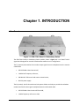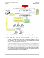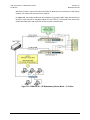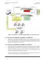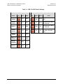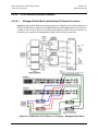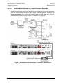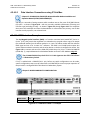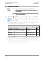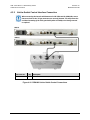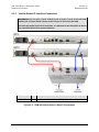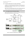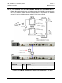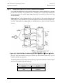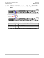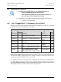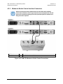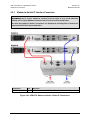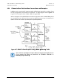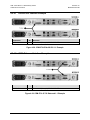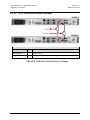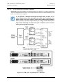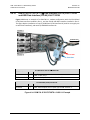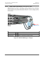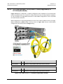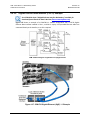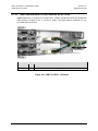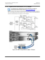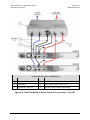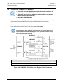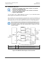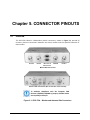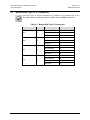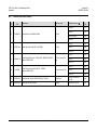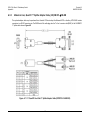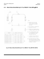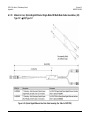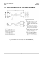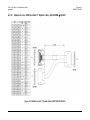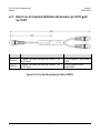
1
CRS-170A L-Band 1:1 Redundancy Switch Installation and Operation Manual Accessory Product for use only with Comtech EF Data CDM-625/A, CDM-840, CDM-750, CDM-760, CDM-570L, CDM-700, CDM-710, CDM-710G, CDM-600L (CLM-9600L), and SDM-300L3 Modems (Modem Firmware and Hardware Requirements Apply) IMPORTANT NOTE: The information contained in this document supersedes all previously published information regarding this product. Product specifications are subject to change without prior notice. Part Number MN/CRS170A.IOM Revision 10 CRS-170A L-Band 1:1 Redundancy Switch Installation and Operation Manual Accessory Product for use only with Comtech EF Data CDM-625/A, CDM-840, CDM-750, CDM-760, CDM-570L, CDM-700, CDM-710, CDM-710G, CDM-600L (CLM-9600L), and SDM-300L3 Modems (Modem Firmware and Hardware Requirements Apply) Part Number MN/CRS170A.IOM Revision 10 Copyright © 2013 Comtech EF Data. All rights reserved. Printed in the USA. Comtech EF Data, 2114 West 7th Street, Tempe, Arizona 85281 USA, 480.333.2200, FAX: 480.333.2161 BLANK PAGE TABLE OF CONTENTS TABLE OF CONTENTS ........................................................................................................................ III TABLES ........................................................................................................................................... VII FIGURES.......................................................................................................................................... VII PREFACE .......................................................................................................................................... XI About this Manual ............................................................................................................................xi Related Documents ...........................................................................................................................xi Conventions and References ............................................................................................................ xii Patents and Trademarks ......................................................................................................................... xii Warnings, Cautions and Notes ............................................................................................................... xii Examples of Multi-Hazard Notices ......................................................................................................... xii Recommended Standard Designations ................................................................................................. xiii Safety and Compliance .................................................................................................................... xiii Electrical Safety and Compliance........................................................................................................... xiii Operating Environment ......................................................................................................................... xiii Equipment Connection .......................................................................................................................... xiv European Union Radio Equipment and Telecommunications Terminal Equipment (R&TTE) Directive (1999/5/EC) and EN 301 489-1 .............................................................................................................. xiv European Union Electromagnetic Compatibility (EMC) Directive (2004/108/EC) ............................ xiv European Union Low Voltage Directive (LVD) (2006/95/EC) ............................................................. xv European Union RoHS Directive (2002/95/EC) .................................................................................. xv European Union Telecommunications Terminal Equipment Directive (91/263/EEC) ....................... xv CE Mark .............................................................................................................................................. xv Product Support............................................................................................................................... xv Comtech EF Data Headquarters ....................................................................................................... xvi Warranty Policy .............................................................................................................................. xvi Limitations of Warranty......................................................................................................................... xvi Exclusive Remedies ................................................................................................................................xvii CHAPTER 1. INTRODUCTION ................................................................................................. 1–1 1.1 Overview ...........................................................................................................................1–1 1.1.1 Modem Side Connectors ......................................................................................................... 1–3 iii CRS-170A L-Band 1:1 Redundancy Switch Table of Contents 1.1.2 Revision 10 MN/CRS170A.IOM Antenna Side Connectors ........................................................................................................ 1–4 1.2 Functional Description ....................................................................................................... 1–4 1.2.1 Operation with CDM-625/A, -840, -750, -760, -570L, -700, -710, -710G Modems ................. 1–5 1.2.1.1 1:1 IP Redundancy Data Switching – Functional Description ......................................... 1–7 1.2.1.1.1 CDM-570L (with Optional IP Module) – Managed Switch or Router Modes ........... 1–7 1.2.1.1.2 CDM-625/A, -750, -760, -700, -710, -710G Managed Switch Mode ........................ 1–9 1.2.1.1.3 CDM-625/A (with Optional IP Packet Processor) – Router Mode .......................... 1–12 1.2.2 Operation with CDM-600L (CLM-9600L) and SDM-300L3..................................................... 1–14 1.2.3 Operation with CDM-600L (CLM-9600L) and CRS-150 .......................................................... 1–14 1.2.4 Operation with SDM-300L3 and SMS-301............................................................................. 1–16 1.3 Summary of Specifications ............................................................................................... 1–17 CHAPTER 2. INSTALLATION ................................................................................................... 2–1 2.1 Unpacking and Inspection .................................................................................................. 2–1 2.2 Mounting...........................................................................................................................2–2 CHAPTER 3. 3.1 MODEM AND SWITCH CONFIGURATION ............................................................. 3–1 Overview ...........................................................................................................................3–1 3.2 Configuring CDM-625/As for 1:1 Redundancy ..................................................................... 3–3 3.2.1 User Remote Ethernet M&C Interface .................................................................................... 3–3 3.2.2 Carrier-in-Carrier® Redundancy Configuration ....................................................................... 3–4 3.3 CDM-840 Operation in 1:1 Redundancy .............................................................................. 3–5 3.4 CDM-750 or CDM-760 Operation in 1:1 Redundancy ........................................................... 3–7 3.5 Configuring CDM-570Ls for 1:1 Redundancy........................................................................ 3–9 3.5.1 IP Redundancy Configuration ................................................................................................ 3–10 3.5.2 Non-IP Redundancy Configuration ........................................................................................ 3–11 3.6 Configuring CDM-700s/CDM-710s/CDM-710Gs for 1:1 Redundancy .................................. 3–13 3.6.1 IP Redundancy Configuration ................................................................................................ 3–14 3.6.2 Non-IP Redundancy Configuration ........................................................................................ 3–14 3.7 CDM-600L (CLM-9600L) Operation in 1:1 Redundancy....................................................... 3–15 3.8 SDM-300L3 Operation in 1:1 Redundancy ......................................................................... 3–15 3.9 CRS-170A Switch DIP Settings ........................................................................................... 3–17 iv CRS-170A L-Band 1:1 Redundancy Switch Table of Contents CHAPTER 4. 4.1 Revision 10 MN/CRS170A.IOM CABLES AND CONNECTIONS ............................................................................... 4–1 Overview ...........................................................................................................................4–1 4.2 Cabling to the CDM-625/A.................................................................................................. 4–3 4.2.1.1 CRS-170A CDM-625/A Control and IF Interface Cabling Kit KT-0000160 .................. 4–3 4.2.2 Modem-to-Switch Control Interface Connection .................................................................... 4–4 4.2.3 Modem-to-Switch IF Interface Connection ............................................................................. 4–5 4.2.3.1 Modem-to-Switch L-Band (Rx/Tx) IF Interface Connection ............................................ 4–5 4.2.3.2 Modem-to-Switch L-Band Tx / 70/140 MHz Rx IF Interface Connection............................... 4–6 4.2.4 Modem-to-User Data Interface Connections and Examples ................................................... 4–7 4.2.4.1 EIA-422/232, V.35 Interface Example ............................................................................. 4–8 4.2.4.2 HSSI Interface Example ................................................................................................... 4–8 4.2.4.3 ASI Interface Example ..................................................................................................... 4–9 4.2.4.4 Quad E1 Interface Example........................................................................................... 4–10 4.2.4.5 G.703 Balanced Interface Example ............................................................................... 4–11 4.2.4.6 G.703 Unbalanced Interface Example .......................................................................... 4–11 4.2.4.7 Overhead Interface Example ........................................................................................ 4–12 4.2.4.8 Engineering Service Channel (ESC) Interface Example ................................................. 4–12 4.2.4.9 10/100 Ethernet Interface Examples ............................................................................ 4–13 4.2.4.9.1 Managed Switch Mode (with/without IP Packet Processor).................................. 4–13 4.2.4.9.2 Router Mode (Optional IP Packet Processor Required) ......................................... 4–14 4.2.4.9.3 Data Interface Connections using IP Sub-Mux ....................................................... 4–15 4.2.4.10 PMSI Interface Example............................................................................................ 4–15 4.3 Cabling to the CDM-840 ................................................................................................... 4–17 4.3.1 CRS-170A CDM-840 Control and IF Interface Cabling Kit KT-0000160 ...................................... 4–17 4.3.2 Unit-to-Switch Control Interface Connection........................................................................ 4–18 4.3.3 Unit-to-Switch IF Interface Connection ................................................................................. 4–19 4.3.4 Unit-to-User Data Interface Connections and Examples....................................................... 4–20 4.3.4.1 RJ-45 Gigabit Ethernet Data Interface Example ........................................................... 4–20 4.3.4.2 KT/12542 G.703 75Ω Data Interface Kit (for G.703 Unbalanced E1) ........................... 4–21 4.4 Cabling to the CDM-750 or CDM-760 ................................................................................ 4–23 4.4.1 Modem-to-Switch Control and IF Interface Connection ....................................................... 4–23 4.4.2 Modem-to-User Data Interface Connections and Examples ................................................. 4–25 4.4.2.1 RJ-45 Gigabit Ethernet Data Interface Example ........................................................... 4–25 4.4.2.2 Optical Gigabit Ethernet Interface Option Example ..................................................... 4–26 4.4.2.3 Serial Data Interface Kit and Connection Examples...................................................... 4–27 4.4.2.3.1 KT/12542 G.703 75Ω Data Interface Kit (for Single G.703 E3/T3 PIIC)................... 4–28 4.5 Cabling to the CDM-570L .................................................................................................. 4–29 4.5.1 CRS-170A CDM-570 1:1 Redundancy Kit KT/10860-1 ...................................................... 4–29 4.5.2 Modem-to-Switch Control Interface Connection .................................................................. 4–30 4.5.3 Modem-to-Switch IF Interface Connection ........................................................................... 4–31 4.5.4 Modem-to-User Data Interface Connections and Examples ................................................. 4–32 4.5.4.1 EIA-422/232 Interface Example .................................................................................... 4–33 4.5.4.2 G.703 Balanced Interface Example ............................................................................... 4–33 v CRS-170A L-Band 1:1 Redundancy Switch Table of Contents 4.5.4.3 4.5.4.4 Revision 10 MN/CRS170A.IOM G.703 Unbalanced Interface Example .......................................................................... 4–34 10/100 Ethernet Interface Example.............................................................................. 4–35 4.6 Cabling to the CDM-700 ................................................................................................... 4–37 4.6.1 Modem-to-Switch Control and IF Interface Connection ....................................................... 4–37 4.6.2 Modem-to-User Data Interface Kit and Connection Examples ............................................. 4–39 4.6.2.1 Dual G.703 E3/T3/STS-1 75Ω Data Interface (CDI-10) Kit KT/12582 and HSSI Data Interface (CDI-60) Kit KT/12586 .................................................................................... 4–40 4.6.2.2 155MB Copper Data Interface (CDI-50) Kit KT/12583 .................................................. 4–41 4.6.2.3 OC-3 Data Interface (CDI-50) Kits KT/12585 (Single-Mode) or KT/12584 (Multi-Mode) ..... ...................................................................................................................................... 4–42 4.6.2.4 Gigabit Ethernet Data Interface (CDI-70) Example ....................................................... 4–43 4.7 Cabling to the CDM-710 ................................................................................................... 4–45 4.7.1 Modem-to-Switch Control and IF Interface Connection ....................................................... 4–45 4.7.2 Modem-to-User Data Interface Kit and Connection Examples ............................................. 4–47 4.7.2.1 ASI 75Ω Data Interface (CDI-40) Kit KT/12579.............................................................. 4–48 4.7.2.2 HSSI Data Interface (CDI-60) Interface Kit KT/12586 .................................................... 4–49 4.7.2.3 Gigabit Ethernet Data Interface (CDI-70) Example ....................................................... 4–50 4.8 Cabling to the CDM-710G ................................................................................................. 4–51 4.8.1 Modem-to-Switch Control and IF Interface Connection ....................................................... 4–51 4.8.2 Modem-to-User Data Interface Kit and Connection Examples ............................................. 4–53 4.8.2.1 Single G.703 E3/T3/STS-1 75Ω Data Interface (CDI-10-1) Kit KT/12583 ........................... 4–54 4.8.2.2 HSSI Data Interface (CDI-60) Kit KT/12586 ................................................................... 4–55 4.8.2.3 Gigabit Ethernet Interface (CDI-70) Example ............................................................... 4–56 4.9 Cabling the CDM-600L (CLM-9600L) .................................................................................. 4–57 4.10 Cabling the SDM-300L3 .................................................................................................... 4–58 CHAPTER 5. CONNECTOR PINOUTS........................................................................................ 5–1 5.1 Overview ...........................................................................................................................5–1 5.2 Modem Side: Type ‘N’ IF Connectors .................................................................................. 5–2 5.3 J3 Control Connector – Modem ‘A’ (Top), DB-9F.................................................................. 5–3 5.4 J4 Control Connector – Modem ‘B’ (Bottom), DB-9F ............................................................ 5–4 5.5 Antenna Side: Type ‘N’ IF Connectors ................................................................................. 5–5 APPENDIX A. CABLE DRAWINGS............................................................................................. A-1 A.1 Introduction ...................................................................................................................... A-1 A.2 Control Interface Cables ..................................................................................................... A-2 vi CRS-170A L-Band 1:1 Redundancy Switch Table of Contents A.2.1 A.2.2 A.2.3 A.2.4 A.2.5 A.2.6 Revision 10 MN/CRS170A.IOM Universal Control Cable, DB-9M DB-9M......................................................................... A-3 Adapter Control Cable, RoHS, DB-9M DB-15F................................................................ A-4 Optional ‘Y’ Splitter Adapter Control Cable, (2X) DB-9M DB-15F .................................. A-5 Optional Control Cable, Non-muting, DB-9M DB-15F .................................................... A-6 Data / Control ‘Y’ Cable, Modem to CRS-170A and CRS-150, DB-25M DB-25M, DB-9MA-7 Control Cable, Modem to CRS-170A and SMS-301, DB-9M DB-15M ............................. A-8 A.3 IF / Data Interface Cables ................................................................................................. A-10 A.3.1 Modem to CRS-170A, L-Band Coaxial Cable, RoHS, Type ‘N’ 50Ω .................................... A-12 A.3.2 Modem to CRS-170A or User, 70/140 MHz Coaxial Cable, RoHS, Type ‘BNC’ 75 Ω .......... A-13 A.3.3 Modem to User, Splitter Cable, (2X) DB-25M DB-25F.................................................. A-14 A.3.4 Modem to User, CDM-625/A Data ‘Y’ Splitter Cable, (2X) DB-9M DB-9F .................... A-15 A.3.5 Modem to User, Quad E1 ‘Y’ Splitter Adapter Cable, (2X) DB-15F DB-9M .................. A-16 A.3.6 Modem to User, Quad E1 ‘Y’ Splitter Adapter Cable, (2X) RJ-48F DB-9M ................... A-17 A.3.7 Modem to User, Quad E1 ‘Y’ Splitter Adapter Cable Kit (KT-0000122) ............................ A-18 A.3.8 Modem to User, Overhead User Data ‘Y’ Splitter Cable, (2X) HD-44M HD-44F .......... A-19 A.3.9 Modem to Modem Shielded Multi-drop CnC® Plus, CDM-625/A 1:1 Cable, DB-9M DB-9M ........................................................................................................................................... A-20 A.3.10 Modem to User, Optical Gigabit Ethernet Single-Mode OR Multi-Mode Cable Assemblies, (2X) Type ‘LC’ (4X) Type ‘LC’ ......................................................................................... A-21 A.3.11 Modem to User, G.703 Balanced User Data ‘Y’ Splitter Cable, (2X) DB-15M DB-15M A-22 A.3.12 Modem to User, HSSI User Data ‘Y’ Splitter Cable, (2X) HD-50M HD-50F ................... A-23 A.3.13 Modem to User, OC-3 Single-Mode OR Multi-Mode Cable Assemblies, Type ‘SC/UPC’ (2X) Type ‘SC/UPC’ ............................................................................................................ A-24 TABLES Table 1-1. CRS-170A Application Summary .............................................................................................. 1–2 Table 3-1. CRS-170A DIP Switch Settings ................................................................................................ 3–18 Table 5-1. Modem Side Type ‘N’ Connectors........................................................................................... 5–2 Table 5-2. J3 - Modem ‘A’ Control Connector Pin Assignments ............................................................... 5–3 Table 5-3. J4 - Modem ‘B’ Control Connector Pin Assignments ............................................................... 5–4 Table 5-4. Antenna Side Type ‘N’ Connectors .......................................................................................... 5–5 FIGURES Figure 1-1. CRS-170A L-Band 1:1 Redundancy Switch .............................................................................. 1–1 Figure 1-2. CRS-170A – Modem Side Connectors ..................................................................................... 1–3 Figure 1-3. CRS-170A – Antenna Side Connectors and Ground Lug ......................................................... 1–4 Figure 1-4. CDM-570L 1:1 IP Redundancy Router Mode – ‘A’ Online ...................................................... 1–8 Figure 1-5. CDM-570L 1:1 IP Redundancy Router Mode – ‘B’ Online (Switchover) ................................. 1–9 Figure 1-6. CDM-625/A, -750, -760, -700, -710, -710G 1:1 IP Redundancy Managed Switch Mode .... ........................................................................................................................................................ 1–10 Figure 1-7. CDM-625/A, -750, -760, -700, -710, -710G 1:1 IP Redundancy Managed Switch Mode – Switchover ...................................................................................................................................... 1–11 vii CRS-170A L-Band 1:1 Redundancy Switch Table of Contents Revision 10 MN/CRS170A.IOM Figure 1-8. CDM-625/A 1:1 IP Redundancy Router Mode – ‘A’ Online .................................................. 1–13 Figure 1-9. CDM-625/A 1:1 IP Redundancy Router Mode – ‘B’ Online (Switchover) ............................. 1–14 Figure 2-1. KT/10254 Mounting Panel Kit (for horizontal or vertical mounting)...................................... 2–2 Figure 3-1. CDM-840 Web Server (HTTP) Interface ‘Utility’ Page............................................................. 3–5 Figure 3-2. CDM-570L Configuration Interfaces ....................................................................................... 3–9 Figure 3-3. CDM-570L CLI 1:1 Redundancy Configuration screen .......................................................... 3–11 Figure 3-4. CRS-170A Antenna Side – DIP Switches ................................................................................ 3–17 Figure 4-1. CDM-625/A Modem-to-Switch Control Connections ............................................................. 4–4 Figure 4-2. CDM-625/A Modem-to-Switch L-Band IF Connections .......................................................... 4–5 Figure 4-3. CDM-625/A Modem-to-Switch L-Band Tx / 70/140 MHz Rx IF Connections ......................... 4–6 Figure 4-4. CDM-625/A Block Diagram: User Modem Switch Traffic ......................................... 4–7 Figure 4-5. CDM-625/A EIA-422/232, V.35 1:1 Example .......................................................................... 4–8 Figure 4-6. CDM-625/A HSSI 1:1 Example ................................................................................................ 4–8 Figure 4-7. CDM-625/A ASI 1:1 Example .................................................................................................. 4–9 Figure 4-8. CDM-625/A Quad E1 1:1 Example ........................................................................................ 4–10 Figure 4-9. CDM-625/A G.703 Balanced 1:1 Example ............................................................................ 4–11 Figure 4-10. CDM-625/A G.703 Unbalanced 1:1 Example ...................................................................... 4–11 Figure 4-11. CDM-625/A Overhead 1:1 Example .................................................................................... 4–12 Figure 4-12. CDM-625/A ESC 1:1 Example .............................................................................................. 4–12 Figure 4-13. CDM-625/A 10/100 Ethernet 1:1 Example – Managed Switch Mode ................................ 4–13 Figure 4-14. CDM-625/A 10/100 Ethernet 1:1 Example – Router Mode................................................ 4–14 Figure 4-15. CDM-625/A PMSI 1:1 Example ........................................................................................... 4–15 Figure 4-16. CDM-840 Unit-to-Switch Control Connections................................................................... 4–18 Figure 4-17. CDM-840 Unit-to-Switch L-Band IF Connections ................................................................ 4–19 Figure 4-18. CDM-840 RJ-45 Gigabit Ethernet 1:1 Example ................................................................... 4–20 Figure 4-19. CDM-840 Unbalanced G.703 E3/T375Ω Interface Kit – KT/12542 ..................................... 4–21 Figure 4-20. CDM-750/CDM-760 Modem-to-Switch Control & IF Connections Kit KT-0000160 ........... 4–24 Figure 4-21. CDM-750/CDM-760 RJ-45 Gigabit Ethernet 1:1 Example .................................................. 4–25 Figure 4-22. CDM-750/CDM-760 Optical Gigabit Ethernet 1:1 Example................................................ 4–26 Figure 4-23. CDM-750/CDM-760 Block Diagram: User Modem Switch Traffic ........................ 4–27 Figure 4-24. CDM-750/CDM-760 G.703 E3/T3 PIIC Interface Kit KT/12542 ........................................... 4–28 Figure 4-25. CDM-570L Modem-to-Switch Control Connections ........................................................... 4–30 Figure 4-26. CDM-570L Modem-to-Switch L-Band IF Connections ........................................................ 4–31 Figure 4-27. CDM-570L Block Diagram: User Modem Switch Traffic ....................................... 4–32 Figure 4-28. CDM-570L EIA-422/232 1:1 Example.................................................................................. 4–33 Figure 4-29. CDM-570L G.703 Balanced 1:1 Example............................................................................. 4–33 Figure 4-30. CDM-570L G.703 Unbalanced 1:1 Example ........................................................................ 4–34 Figure 4-31. CDM-570L 10/100 Ethernet 1:1 Example ........................................................................... 4–35 Figure 4-32. CDM-700 Modem-to-Switch Control & IF Connections – KT/12551 .................................. 4–38 Figure 4-33. CDM-700 Block Diagram: User Modem Switch Traffic......................................... 4–39 Figure 4-34. CDM-700 G.703 E3/T3/STS-1 / HSSI 1:1 Example ................................................................ 4–40 Figure 4-35. CDM-700 155MB Copper 1:1 Example ............................................................................... 4–41 Figure 4-36. CDM-700 OC-3 1:1 Example (Single-Mode shown) ............................................................ 4–42 Figure 4-37. CDM-700 Gigabit Ethernet (GigE) 1:1 Example .................................................................. 4–43 Figure 4-38. CDM-710 Modem-to-Switch Control & IF Connections – KT/12551 .................................. 4–46 Figure 4-39. CDM-710 Block Diagram: User Modem Switch Traffic......................................... 4–47 Figure 4-40. CDM-710 ASI 1:1 Example .................................................................................................. 4–48 viii CRS-170A L-Band 1:1 Redundancy Switch Table of Contents Revision 10 MN/CRS170A.IOM Figure 4-41. CDM-710 HSSI 1:1 Example ................................................................................................ 4–49 Figure 4-42. CDM-710 Gigabit Ethernet (GigE) 1:1 Example .................................................................. 4–50 Figure 4-43. CDM-710G Modem-to-Switch Control & IF Connections – KT/12551 ............................... 4–52 Figure 4-44. CDM-710G Block Diagram: User Modem Switch Traffic ........................................ 4–53 Figure 4-45. CDM-710G Single G.703 E3/T3/STS-1 1:1 Example.............................................................. 4–54 Figure 4-46. CDM-710G HSSI 1:1 Example .............................................................................................. 4–55 Figure 4-47. CDM-710G Gigabit Ethernet (GigE) 1:1 Example ................................................................ 4–56 Figure 4-48. CDM-600L (CLM-9600L) Block Diagram: Cable Connections .............................................. 4–57 Figure 4-49. SDM-300L3 Block Diagram: Cable Connection ................................................................... 4–58 Figure 5-1. CRS-170A – Modem and Antenna Side Connectors ............................................................... 5–1 Figure A-1. Universal Control Cable (CEFD P/N CA/WR9378-4) .............................................................. A-3 Figure A-2. Adapter Control Cable (CEFD P/N CA/WR12135-1) ............................................................... A-4 Figure A-3. Optional ‘Y’ Splitter Adapter Control Cable, (CEFD P/N CA/WR13011-4) .............................. A-5 Figure A-4. Optional Control Cable (CEFD P/N CA-0000187) .................................................................... A-6 Figure A-5. Data / Control ‘Y’ Cable (CEFD P/N CA/WR10456-4).............................................................. A-7 Figure A-6. Control Cable (CEFD P/N CA/WR10163-1) ............................................................................. A-8 Figure A-7. Tx/Rx 50Ω Type ‘N’ Coaxial Cable (CEFD P/N CA/RF10453-4) .............................................. A-12 Figure A-8. Tx/Rx/User Data 75Ω Type ‘BNC’ Coaxial Cable (CEFD P/N CA/BNC75OHM) ...................... A-13 Figure A-9. 1:1 User Data Splitter Cable (CEFD P/N CA/RB10461-1) ...................................................... A-14 Figure A-10. 1:1 User Data ‘Y’ Splitter Cable (CEFD P/N CA-0000071) ................................................... A-15 Figure A-11. 1:1 Quad E1 User Data ‘Y’ Splitter Adapter Cable (CEFD P/N CA-0000163)....................... A-16 Figure A-12. Quad E1 User Data ‘Y’ Splitter Adapter Cable (CEFD P/N CA-0000164)............................. A-17 Figure A-13. Quad E1 User Data ‘Y’ Splitter Adapter Cable Kit (CEFD P/N KT-0000122) ........................ A-18 Figure A-14. Overhead User Data ‘Y’ Splitter Cable (CEFD P/N CA-0000070) ........................................ A-19 Figure A-15. Modem to Modem Shielded Multi-drop CnC® Plus, CDM-625/A 1:1 Cable (CEFD P/N CA-0000276) ................................................................................................................................... A-20 Figure A-16. Optical Gigabit Ethernet User Data Cable Assembly (See Table for CEFD P/N) ................. A-21 Figure A-17. G.703 Balanced User Data ‘Y’ Splitter Cable (CEFD P/N CA/WR10522-1) .......................... A-22 Figure A-18. HSSI User Data ‘Y’ Splitter Cable (CEFD P/N PP/SC3523) ................................................... A-23 Figure A-19. OC-3 User Data Cable Assembly (See Table for CEFD P/N) ................................................ A-24 ix CRS-170A L-Band 1:1 Redundancy Switch Table of Contents Revision 10 MN/CRS170A.IOM BLANK PAGE x PREFACE About this Manual This manual provides installation and operation information for the Comtech EF Data CRS-170A L-Band 1:1 Redundancy Switch. This is a technical document intended for the persons responsible for the operation and maintenance of the CRS-170A and its supported modems. Related Documents • Comtech EF Data CDM-625A Advanced Satellite Modem Installation and Operation Manual (CEFD P/N MN-CDM625A) • Comtech EF Data CDM-625 Advanced Satellite Modem Installation and Operation Manual (CEFD P/N MN-CDM625) • Comtech EF Data CDM-840 Remote Router Installation and Operation Manual (CEFD P/N MN-CDM840) • Comtech EF Data CDM-750 Advanced High-Speed Trunking Modem Installation and Operation Manual (CEFD P/N CDM-750) • Comtech EF Data CDM-760 Advanced High-Speed Trunking Modem Installation and Operation Manual (CEFD P/N CDM-760) • Comtech EF Data CDM-570/CDM-570L/CDMR-570L Satellite Modem Installation and Operation Manual (CEFD P/N MN/CDM570L.IOM) • Comtech EF Data CDM-700 Satellite Modem Installation and Operation Manual (CEFD P/N MN/CDM700.IOM) • Comtech EF Data CDM-710 Broadcast Satellite Modem Installation and Operation Manual (CEFD P/N CDM710.IOM) • Comtech EF Data CDM-710G Satellite Modem Installation and Operation Manual (CEFD P/N MN-CDM710G) xi CRS-170A L-Band 1:1 Redundancy Switch Preface Revision 10 MN/CRS170A.IOM • Comtech EF Data CDM-600L Satellite Modem Installation and Operation Manual (CEFD P/N MN/CDM600L.IOM) • Comtech EF Data CLM-9600L Open Network Satellite Modem Installation and Operation Manual (CEFD P/N MN/CLM9600L.IOM) • Comtech EF Data SDM-300L3 Satellite Modem Installation and Operation Manual (CEFD P/N MN/SDM300L3.IOM) Conventions and References Patents and Trademarks See all of Comtech EF Data's Patents and Patents Pending at http://patents.comtechefdata.com. Comtech EF Data acknowledges that all trademarks are the property of the trademark owners. Warnings, Cautions and Notes A WARNING informs you about a possible hazard that MAY CAUSE DEATH or SERIOUS INJURY. A CAUTION informs you about a possible hazard that MAY CAUSE INJURY or PROPERTY DAMAGE. A NOTE gives you important information about a task or the equipment. A REFERENCE directs you to additional information about a task or the equipment. Examples of Multi-Hazard Notices xii CRS-170A L-Band 1:1 Redundancy Switch Preface Revision 10 MN/CRS170A.IOM Recommended Standard Designations The new designation of the Electronic Industries Association (EIA) supersedes the Recommended Standard (RS) designations. References to the old designations may be shown when depicting actual text (e.g., RS-232) displayed on front panel menus, Web Server pages, serial remote interfaces, Telnet Command Line Interfaces (CLIs), or unit rear panels. All other references in the manual refer to EIA designations. The user should carefully review the following information. Safety and Compliance Electrical Safety and Compliance The unit complies with the EN 60950 Safety of Information Technology Equipment (Including Electrical Business Machines) safety standard. The equipment is rated for operation at ±12 volts DC. It has a maximum power consumption of 4.5 Watts, and draws a maximum of 250 mA at +12 volts DC and 120 mA at -12 volts DC. The power supply current is, in all circumstances, supplied by either a single Comtech EF Data modem, or a pair of these modems. IF THE UNIT IS OPERATED IN A VEHICLE OR MOVABLE INSTALLATION, MAKE SURE THE UNIT IS STABLE. OTHERWISE, EN 60950 SAFETY IS NOT GUARANTEED. Operating Environment DO NOT OPERATE THE UNIT IN ANY OF THESE EXTREME OPERATING CONDITIONS: • AMBIENT TEMPERATURES LESS THAN 0° C (32° F) OR MORE THAN 50° C (122° F). • PRECIPITATION, CONDENSATION, OR HUMID ATMOSPHERES OF MORE THAN 95% RELATIVE HUMIDITY. • UNPRESSURIZED ALTITUDES OF MORE THAN 2000 METRES (6561.7 FEET). • EXCESSIVE DUST. • FLAMMABLE GASES. • CORROSIVE OR EXPLOSIVE ATMOSPHERES. xiii CRS-170A L-Band 1:1 Redundancy Switch Preface Revision 10 MN/CRS170A.IOM Equipment Connection THE CRS-170A IS DESIGNED FOR OPERATION ONLY WITH THE COMTECH EF DATA PRODUCTS LISTED IN THIS MANUAL UNDER ‘RELATED DOCUMENTS’. THESE PRODUCTS SUPPLY DC OPERATING CURRENT (ELECTRONICALLY FUSED AND PROTECTED) AND CONTROL SIGNALS FOR THE CORRECT FUNCTIONING OF THIS SWITCH. CONNECTION TO OTHER MANUFACTURERS’ EQUIPMENT COULD RESULT IN DAMAGE TO THE SWITCH. THE CRS-170A IS NOT COMPATIBLE WITH OTHER COMTECH EF DATA MODEMS OR PRODUCTS NOT LISTED IN THIS MANUAL. European Union Radio Equipment and Telecommunications Terminal Equipment (R&TTE) Directive (1999/5/EC) and EN 301 489-1 Independent testing verifies that the unit complies with the European Union R&TTE Directive, its reference to EN 301 489-1 (Electromagnetic compatibility and Radio spectrum Matters [ERM]; ElectroMagnetic Compatibility [EMC] standard for radio equipment and services, Part 1: Common technical requirements), and the Declarations of Conformity for the applicable directives, standards, and practices that follow: European Union Electromagnetic Compatibility (EMC) Directive (2004/108/EC) • Emissions: EN 55022 Class B – Limits and Methods of Measurement of Radio Interference Characteristics of Information Technology Equipment. • Immunity: EN 55024 – Information Technology Equipment: Immunity Characteristics, Limits, and Methods of Measurement. • EN 61000-3-2 – Harmonic Currents Emission • EN 61000-3-3 – Voltage Fluctuations and Flicker. • Federal Communications Commission Federal Code of Regulation FCC Part 15, Subpart B. TO ENSURE THAT THE UNIT COMPLIES WITH THESE STANDARDS, OBEY THESE INSTRUCTIONS: • Use coaxial cable that is of good quality (e.g., RG58/U (50Ω) or RG59/U (75Ω)) for connections to the IF Tx and Rx (transmit and receive) BNC female connectors. • Use Type 'D' connectors that have back-shells with continuous metallic shielding. Type ‘D’ cabling must have a continuous outer shield (either foil or braid, or both). The shield must be bonded to the back-shell. xiv CRS-170A L-Band 1:1 Redundancy Switch Preface • Revision 10 MN/CRS170A.IOM Operate asll products with their covers on at all times. European Union Low Voltage Directive (LVD) (2006/95/EC) Symbol Description <HAR> Type of power cord required for use in the European Community. CAUTION: Double-pole/Neutral Fusing ACHTUNG: Zweipolige bzw. Neutralleiter-Sicherung ! International Symbols Symbol Definition Symbol Definition Alternating Current Protective Earth Fuse Chassis Ground For additional symbols, refer to Warnings, Cautions and Notes listed earlier in this Preface. European Union RoHS Directive (2002/95/EC) This unit satisfies (with exemptions) the requirements specified in the European Union Directive on the Restriction of Hazardous Substances in Electrical and Electronic Equipment (EU RoHS, Directive 2002/95/EC). European Union Telecommunications Terminal Equipment Directive (91/263/EEC) In accordance with the European Union Telecommunications Terminal Equipment Directive 91/263/EEC, do not directly connect the unit to the Public Telecommunications Network. CE Mark Comtech EF Data declares that the unit meets the necessary requirements for the CE Mark. Product Support For all product support, please call: +1.240.243.1880 +1.866.472.3963 (toll free USA) xv CRS-170A L-Band 1:1 Redundancy Switch Preface Revision 10 MN/CRS170A.IOM Comtech EF Data Headquarters http://www.comtechefdata.com Comtech EF Data Corp. 2114 West 7th Street Tempe, Arizona USA 85281 +1.480.333.2200 Warranty Policy Comtech EF Data products are warranted against defects in material and workmanship for a specific period from the date of shipment, and this period varies by product. In most cases, the warranty period is two years. During the warranty period, Comtech EF Data will, at its option, repair or replace products that prove to be defective. Repairs are warranted for the remainder of the original warranty or a 90 day extended warranty, whichever is longer. Contact Comtech EF Data for the warranty period specific to the product purchased. For equipment under warranty, the owner is responsible for freight to Comtech EF Data and all related customs, taxes, tariffs, insurance, etc. Comtech EF Data is responsible for the freight charges only for return of the equipment from the factory to the owner. Comtech EF Data will return the equipment by the same method (i.e., Air, Express, Surface) as the equipment was sent to Comtech EF Data. All equipment returned for warranty repair must have a valid RMA number issued prior to return and be marked clearly on the return packaging. Comtech EF Data strongly recommends all equipment be returned in its original packaging. Comtech EF Data Corporation’s obligations under this warranty are limited to repair or replacement of failed parts, and the return shipment to the buyer of the repaired or replaced parts. Limitations of Warranty The warranty does not apply to any part of a product that has been installed, altered, repaired, or misused in any way that, in the opinion of Comtech EF Data Corporation, would affect the reliability or detracts from the performance of any part of the product, or is damaged as the result of use in a way or with equipment that had not been previously approved by Comtech EF Data Corporation. xvi CRS-170A L-Band 1:1 Redundancy Switch Preface Revision 10 MN/CRS170A.IOM The warranty does not apply to any product or parts thereof where the serial number or the serial number of any of its parts has been altered, defaced, or removed. The warranty does not cover damage or loss incurred in transportation of the product. The warranty does not cover replacement or repair necessitated by loss or damage from any cause beyond the control of Comtech EF Data Corporation, such as lightning or other natural and weather related events or wartime environments. The warranty does not cover any labor involved in the removal and or reinstallation of warranted equipment or parts on site, or any labor required to diagnose the necessity for repair or replacement. The warranty excludes any responsibility by Comtech EF Data Corporation for incidental or consequential damages arising from the use of the equipment or products, or for any inability to use them either separate from or in combination with any other equipment or products. A fixed charge established for each product will be imposed for all equipment returned for warranty repair where Comtech EF Data Corporation cannot identify the cause of the reported failure. Exclusive Remedies Comtech EF Data Corporation’s warranty, as stated is in lieu of all other warranties, expressed, implied, or statutory, including those of merchantability and fitness for a particular purpose. The buyer shall pass on to any purchaser, lessee, or other user of Comtech EF Data Corporation’s products, the aforementioned warranty, and shall indemnify and hold harmless Comtech EF Data Corporation from any claims or liability of such purchaser, lessee, or user based upon allegations that the buyer, its agents, or employees have made additional warranties or representations as to product preference or use. The remedies provided herein are the buyer’s sole and exclusive remedies. Comtech EF Data shall not be liable for any direct, indirect, special, incidental, or consequential damages, whether based on contract, tort, or any other legal theory. xvii CRS-170A L-Band 1:1 Redundancy Switch Preface Revision 10 MN/CRS170A.IOM Notes: xviii Chapter 1. INTRODUCTION 1.1 Overview Figure 1-1. CRS-170A L-Band 1:1 Redundancy Switch The CRS-170A L-Band 1:1 Redundancy Switch module, shown in Figure 1-1, is an L-Band Tx-Rx IF signal switch designed for use with L-Band satellite modems in a 1:1 configuration. The Tx (transmit) side switches four modem output signals that are multiplexed onto the transmit coaxial cable: • 950-2250 MHz L-band transmit RF; • 10 MHz BUC frequency reference; • 600 KHz BUC FSK control and status communication; • BUC DC power supply. The Rx (receive) side of the switch uses both power dividers and relays to provide the redundant modem interface for three signals multiplexed onto the LNB coaxial cable: • 950-2250 MHz L-band receive RF from LNB; • 10 MHz frequency reference to LNB; 1–1 CRS-170A L-Band 1:1 Redundancy Switch Introduction • Revision 10 MN/CRS170A.IOM DC power supply to LNB. The CRS-170A monitors the faults of both modems and determines which modem should be online. The data switch is built into each terrestrial data interface inside both modems (excluding CDM-600L [CLM-9600L] and SLM-300L3). The CRS-170A is designed to support 1:1 redundancy for Comtech EF Data CDM-625/A, CDM-840, CDM-750, CDM-760, CDM-570L, CDM-700, CDM-710, CDM-710G, CDM-600L (CLM-9600L), and SDM-300L3 modems. Table 1-1 summarizes the CRS-170A 1:1 IF Switch applications, including requirements for supporting data switching hardware and software. Table 1-1. CRS-170A Application Summary Modem 1:1 Data Switch (See Note 1) Other Information (See Notes 2,3) CDM-625/A Built into the CDM-625/A Firmware Ver. 1.1.1 or higher CDM-840 Built into the CDM-840 Firmware Ver. 1.2.4 or higher CDM-750 Built into the CDM-750 Firmware Ver. 1.1.1 or higher CDM-760 Built into the CDM-760 Firmware Ver. 1.1.1 or higher CDM-570L Built into the CDM-570L Firmware Ver. 1.6.7 or higher CDM-570L IP Module User-provided hub or Layer 2 switch Firmware Ver. 1.5.4.2 or higher CDM-700 Built into the CDM-700 CDM-710 Built into the CDM-710 CDM-710G Built into the CDM-710G Firmware Ver. 5.1.1 or higher CDM-600L (CLM-9600L) CRS-150 Firmware Ver. 1.1.4 or higher; Hardware Rev. 3 or higher SDM-300L3 SMS-301 Special version of SMS-301 Firmware Ver. 1.1.6 or higher; Chassis Rev. A or higher Firmware Ver. 2.4.1 or higher; Chassis Rev. A or higher Notes: 1. For detailed information about the CRS-150 and SMS-301 switches, refer to their respective Installation and Operation Manuals. 2. Order modems with Type ‘N’ connectors. 3. Firmware updates are free and may be downloaded from the Comtech EF Data web page. If a modem does not meet the hardware requirements, contact CEFD – hardware revision upgrades must be performed at CEFD The off-line modem holds its Rx terrestrial data in TRI-STATE® as commanded by the CRS-170A Switch. Because of this, it is very important to power down the off-line modem before disconnecting the modem from the Switch. The CDM-600L (CLM-9600L) and SDM-300L3 modems do not have built-in switching capability for the terrestrial data side of the link. For the CDM-600L (CLM-9600L), 1:1 redundancy requires both a CRS-150 switch to act as controller and terrestrial data switch and a CRS-170A to perform the LBand switching. The CRS-170A is required because the CRS-150 RF switching is limited to the 1–2 CRS-170A L-Band 1:1 Redundancy Switch Introduction Revision 10 MN/CRS170A.IOM 70/140 MHz band, and will not handle the high current BUC power supply multiplexed onto the transmit coaxial cable. Similarly, the SDM-300L3 requires an SMS-301 switch together with the CRS-170A. In both cases, the CRS-170A is controlled by the supporting data switch, and places the “A” or “B” modem RF online to match the data switch state. The CDM-600L (CLM-9600L) modems supply redundant power to the CRS-170A through the CRS-150. The SMS-301 itself has redundant power supplies, and feeds power to the CRS-170A through the control cable. Online/standby modem configuration matching is provided by the CRS-150 controller communication with the CDM-600L (CLM-9600L) modem. The SMS-301 does not automatically configure the standby modem. THE CRS-150 IS AN ACCESSORY PRODUCT DESIGNED SPECIFICALLY FOR THE COMTECH EF DATA CDM-600 AND CDM-600L (CLM-9600L) MODEMS, AND MUST NOT BE USED WITH ANY OTHER EQUIPMENT. 1.1.1 Modem Side Connectors The modem side connectors, shown in Figure 1-2 and outlined in the accompanying table, provide all necessary external connections between the CRS-170A L-Band 1:1 Redundancy Switch module and the specified Comtech EF Data modems. J6 | TX B J5 | TX A Name Ref Des RX A J3 | Control A J4| Control B J2 | RX B J1 | RX A Connector Type Function J1 Type ‘N’ RF Input to Modem A RX B J2 Type ‘N’ RF Input to Modem B Control A J3 DB-9F (9-pin Type ‘D’ female) Control Interface with Modem A Control B J4 DB-9F (9-pin Type ‘D’ female) Control Interface with Modem B TX A J5 Type ‘N’ RF Output from Modem A TX B J6 Type ‘N’ RF Output from Modem B Figure 1-2. CRS-170A – Modem Side Connectors 1–3 CRS-170A L-Band 1:1 Redundancy Switch Introduction Revision 10 MN/CRS170A.IOM 1.1.2 Antenna Side Connectors Two 50Ω female Type ‘N’ connectors on the antenna side of the CRS-170A L-Band 1:1 Redundancy Switch module provide the coaxial cable connections to the outdoor transmit and receive equipment (BUC and LNB). Refer to Figure 1-3 and its accompanying table for details (this image depicts the Rev. A and later versions of the CRS-170A). Type ‘N’ Connector Name Ref Des RX TX J7 J8 Description Direction RF Input In LNB 10 MHz Ref Out LNB Power Out RF Output Out BUC 10 MHz Ref Out BUC FSK In/Out Comm. Out Figure 1-3. CRS-170A – Antenna Side Connectors and Ground Lug 1.2 Functional Description The CRS-170A L-Band 1:1 Redundancy Switch module performs the Tx and Rx coaxial switching required for redundant modem operation with an outdoor BUC and LNB. It switches all of the BUC and LNB interface signals that are multiplexed onto the Tx and Rx coaxial cables: • Tx and Rx L-Band signals; • 10 MHz reference to BUC and LNB; • DC Power to BUC and LNB; • FSK signaling to the BUC. 1–4 CRS-170A L-Band 1:1 Redundancy Switch Introduction Revision 10 MN/CRS170A.IOM 1.2.1 Operation w ith CDM-625/A, -840, -750, -760, -570L, -700, -710, -710G Modems The CRS-170A is configured with two modems to form a complete 1:1 redundant modem system. Within the CRS-170A, a redundancy controller continually monitors the status of faults for both modems to determine which modem should be Online and Offline. The control cables between the modems and the CRS-170A include four signal groups: • First, serial full-duplex communication lines are routed from one modem to the other modem via the CRS-170A. Using these lines, this Online modem can interrogate the Offline modem at regular intervals to determine its configuration. If a difference in configuration is detected, the Online modem will reconfigure the Offline modem so that the configurations are always synchronized. This process is entirely automatic – if the Offline modem is replaced, it does not have to be manually reprogrammed to match the Online modem. • Second, the Unit, Tx and Rx faults signals from both modems are routed to the CRS-170A. This allows the redundancy controller to always know the health status of both modems. • Third, the online/offline signals are routed from the CRS-170A to each modem. Based on the modem faults, the CRS-170A will determine which modem should be Online and Offline. In the event that both modems indicate faults through some malfunction, the CRS-170A switch will select, by default, Modem A. • Fourth, +12V is routed from each modem to the CRS-170A for operational power. This power from both modems is diode OR’d so that the switch remains active if power is lost from one of the modems. Mode Switches – The Mode DIP switches, located on the antenna side of the CRS-170A, allow the switch to operate in two different modes: Normal (Intelligent Controller) Mode and SDM-300L/CDM-600L (Dumb Controller) Mode. • Use Normal (Intelligent Controller) Mode for CDM-625/A, CDM840, CDM-750, CDM-760, CDM-570L, CDM-700, CDM-710 and CDM-710G modems. • Use SDM-300L/CDM-600L (Dumb Controller) Mode for SDM-300L and CDM-600L (CLM-9600L) modems. IF Switching – The CRS-170A provides L-Band redundancy, but when switching occurs, it accommodates more than just the L-Band signals: • On the Tx side, it switches the Tx L-Band signal, the 10 MHz reference to the BUC, DC power to the BUC and, on CDM-570L modems, FSK signaling to the BUC. 1–5 CRS-170A L-Band 1:1 Redundancy Switch Introduction • Revision 10 MN/CRS170A.IOM On the Rx side, it switches the 10 MHz reference to the LNB, and DC power to the LNB. The Rx L-Band signal from the LNB is split in a power divider to continuously drive both the Online and Offline demodulator. The Offline demodulator can then maintain lock so that it is ready to quickly assume Online status for receive traffic when a switchover is required. Data Switching is accomplished inside each modem, in the data interface itself. A ‘Y’ cable connects both the Online modem and the Offline modem to the terrestrial data source. Transmit data drives both modems in parallel so that the standby modulator is always ready to come Online. Termination impedance for the modem line receivers is active in the Online modem. On the Rx side of the interface, TRI-STATE® control of the Offline modem line drivers keeps the Offline modem from interfering with the Rx data traffic. Send timing output from the Offline modem is also TRI-STATE®1. You must enable Manual Switching via the Online modem, through its front panel, or by remote control. You must control Automatic Switching Selection via the Online modem. Then, from the CRS-170A, you must determine the conditions that cause an automatic switchover using two DIP switches – Unit+Tx and Unit+Rx – located on the antenna side of the CRS-170A and labeled Switch Conditions. This selection provides a great deal of flexibility in the operation of the switch: you can select between Modem Unit faults only; Modem Unit faults or Receive Traffic faults; Modem Unit faults or Transmit Traffic faults; or all three. Also located on the antenna side of the CRS-170A are two green LEDs that indicate which modem is Online. With the ‘bridging’ architecture of the CRS-170A (whereby identical terrestrial data traffic signals are routed to both Online and Offline modems), the redundancy controller can avoid unnecessary switchovers. By examining the fault status of both modems, it can infer if the fault is external to the system. For example, the CRS-170A has been configured to switch following Unit faults or Transmit Traffic faults, and the modems have been configured for external clock operation. Now, suppose that the external equipment (network, multiplex, router, etc.) fails – both the Offline and Online modems will now show a Transmit Traffic fault (No Clock Detected from Terrestrial Port). The CRS-170A Controller State Machine will see that both faults have occurred at the same time (in fact, within a 0.5 second window), and infers that the fault is external. Therefore, no unnecessary switchover is initiated. 1 TRI-STATE is a registered trademark of National Semiconductor. 1–6 CRS-170A L-Band 1:1 Redundancy Switch Introduction Revision 10 MN/CRS170A.IOM 1.2.1.1 1:1 IP Redundancy Data Switching – Functional Description 1.2.1.1.1 CDM-570L (with Optional IP Module) – Managed Switch or Router Modes • Do not use the M&C Ethernet port (bottom RJ-45 connector) when the optional IP Module is installed. • All configuration changes can only be made to the Online Modem and will require you to “Save Parameters to permanent storage” to ensure the configuration change is also applied to the Backup Modem. Managed Switch (Ethernet Bridge) Mode – For the CDM-570L in Managed Switch Mode (also known as “Ethernet Bridge Mode”) you MUST use an external Ethernet hub to insure that traffic will continue after a switchover. If an Ethernet switch is used, there could be a several minute outage while the Ethernet Switch “re-learns” the correct output Ethernet port. Using a “dumb” Ethernet hub allows LAN-to-WAN traffic to continue even after a switchover occurs since both modems will be receiving the LAN traffic. In Managed Switch Mode, both modems should be assigned a unique Management IP address on the same subnet in order to share the parameter file. Router Mode – For the CDM-570L in Router Mode, you should use an external Ethernet switch. Router Mode does not require a “dumb” hub as with Managed Switch Mode, and for performance reasons an Ethernet switch is highly recommended. In Router Mode, both modems must be assigned a unique Management IP address on the same subnet (172.18.10.21/24 and 172.18.10.22/24 as shown in Figure 1-4 and Figure 1-5). This is used to share the param file. A Traffic IP address on the subnet must also be assigned (172.18.10.20/24) in the online modem. Whichever modem is online will assume the Traffic IP. When there is a switchover to the backup modem, this modem will now assume the Traffic IP. As shown in Figure 1-5, the backup modem will also broadcast a “gratuitous ARP” that will tell all local devices to now associate a new MAC address for the Traffic IP 172.18.10.20. Each device will update their ARP tables and traffic will resume virtually instantaneously. 1–7 CRS-170A L-Band 1:1 Redundancy Switch Introduction Revision 10 MN/CRS170A.IOM Figure 1-4. CDM-570L 1:1 IP Redundancy Router Mode – ‘A’ Online 1–8 CRS-170A L-Band 1:1 Redundancy Switch Introduction Revision 10 MN/CRS170A.IOM Figure 1-5. CDM-570L 1:1 IP Redundancy Router Mode – ‘B’ Online (Switchover) 1.2.1.1.2 CDM-625/A, -750, -760, -700, -710, -710G Managed Switch Mode A standard, user-provided Ethernet Layer 2 Switch is needed when a CDM-625/A, CDM-750, CDM-760, CDM-700, CDM-710, or CDM-710G modem is configured for Managed Switch Mode (also known as “Ethernet Bridge Mode”) terrestrial traffic. A Layer 2 Switch is designed to limit the traffic that egresses each port by only sending Ethernet packets out the port that the destination network device is located. The switch maintains a table, known as the dynamic Content-Addressable Memory (CAM) table that maps MAC addresses to switch ports. When a packet arrives, in which an entry for that specific destination MAC is unknown to the switch, it sends the packet out all ports and waits for response packets in an attempt to identify which port that particular MAC resides. Once the device responds, the switch is able to map the MAC to the port in the CAM table. 1–9 CRS-170A L-Band 1:1 Redundancy Switch Introduction Revision 10 MN/CRS170A.IOM Any new packets arriving destined for that MAC address will be forwarded only out the port identified in the CAM table. Most switch CAM tables do have a flush or timeout value, but is normally set to a very high number to limit the amount of times the switch has to broadcast a packet out all ports. It is also important to note that CAM entries for a specific port are cleared when a port link goes down. Figure 1-6. CDM-625/A, -750, -760, -700, -710, -710G 1:1 IP Redundancy Managed Switch Mode Figure 1-6 shows a 1:1 IP Redundancy setup in Managed Switch Mode, with the Ethernet data interface of both CEFD modems connected to a Layer 2 Switch. Both modems are operational – Modem ‘A’ is Online and connected to Port 4 of the Layer 2 Switch. Modem ‘B’ is Offline and connected to Port 3 of the Layer 2 Switch, but the Ethernet link is not active because only the Online modem will have an active Ethernet data interface. Also, Local PC ‘A’ is connected to Port 1 of the Layer 2 Switch. When Ethernet traffic is sent from Local PC ‘A’ across the satellite link to remote PC ‘B’, the Layer 2 Switch will “learn” the MAC addresses of both PCs and will have these dynamic entries in its CAM Table: Port 1 MAC 00-00-00-00-00-11 (Local PC ‘A’) Port 3 No entries, port down Port 4 MAC 00-00-00-00-00-22 (Remote PC ‘B’) 1–10 CRS-170A L-Band 1:1 Redundancy Switch Introduction Revision 10 MN/CRS170A.IOM Figure 1-7. C DM-625/A, -750, -760, -700, -710, -710G 1: 1 IP R edundancy Managed S witc h Mode – S witc hover As shown in Figure 1-7, in the event of a fault occurring on the Online Modem ‘A’, the following will occur: • Modem ‘A’ goes Offline and disables its Ethernet data interface. • Simultaneously, Modem ‘B’ goes Online and enables its Ethernet data interface. • Layer 2 Switch ‘A’ senses that Port 4 is no longer active and clears the CAM table entries for that port. • When the next Ethernet packet from Local PC ‘A’ destined for Remote PC ‘B’ arrives at Switch ‘A’, there is no CAM entry for the PC ‘B’ MAC, so it will be broadcast to all active ports. • When the next Ethernet packet from Remote PC ‘B’ arrives at Switch ‘A’, Switch ‘A’ dynamically adds the PC ‘B’ MAC to the CAM table for Port 3. 1–11 CRS-170A L-Band 1:1 Redundancy Switch Introduction Revision 10 MN/CRS170A.IOM Note the following: 1. The Managed Switch Mode method of redundancy is intended to be equivalent to pulling the Ethernet cable from one port and putting it into a different port on the same switch. 2. For the CDM-625/A modem: You may configure one of the CDM-625/A’s four available 10/100 Ethernet ports for M&C Ethernet. As configured in Dedicated Management Port Mode, when the modem is offline the M&C-designated port remains functional and available for operation, while the three remaining ports are unavailable. Otherwise, if none of the 10/100 Ethernet ports are reserved for M&C operation, all four ports become unavailable when the modem is offline. This configuration must be enabled on both modems. Refer to the CDM-625 or CDM-625A Advanced Satellite Modem Installation and Operation Manuals for instructions to configure one of the four 10/100 Ethernet ports for each modem for remote Ethernet M&C. Dedicated Management Port Mode is not configurable for use when the optional IP Packet Processor is installed and enabled. With the IP Packet Processor enabled, as a means to avoid Ethernet Networking Loops, only one of the CDM-625/A’s four 10/100 Ethernet Ports is used for each modem at any given time. 3. For the CDM-750, -760, -700, -710, and -710G modems: When the modem is offline, although all GigE port(s) are unavailable, the M&C Ethernet port remains functional and available for operation. 4. Installation must use a true switching device, not a hub device. 1.2.1.1.3 CDM-625/A (with Optional IP Packet Processor) – Router Mode All configuration changes can only be made to the Online Modem and will require you to “Save Parameters to permanent storage” to ensure the configuration change is also applied to the Backup Modem. For the CDM-625/A with the optional IP Packet Processor installed and enabled and the configuration set for Router Mode, you must provide an external Ethernet switch. In Router Mode, both modems must be assigned a unique Management IP address on the same subnet (172.18.10.21/24 and 172.18.10.22/24 as shown in Figure 1-8 and Figure 1-9). This is used to share the param file. A Traffic IP address on the subnet must also be assigned (172.18.10.20/24) in the online modem. The Traffic IP Address must be different from either Management IP Address. 1–12 CRS-170A L-Band 1:1 Redundancy Switch Introduction Revision 10 MN/CRS170A.IOM Whichever modem is online will assume the Traffic IP. When there is a switchover to the backup modem, this modem will now assume the Traffic IP. Per Figure 1-9, the backup modem will also broadcast a “gratuitous ARP” which will tell all local devices to now associate a new MAC address for the Traffic IP 172.18.10.20. Each device will update their ARP tables and traffic will resume virtually instantaneously. Figure 1-8. CDM-625/A 1:1 IP Redundancy Router Mode – ‘A’ Online 1–13 CRS-170A L-Band 1:1 Redundancy Switch Introduction Revision 10 MN/CRS170A.IOM Figure 1-9. CDM-625/A 1:1 IP Redundancy Router Mode – ‘B’ Online (Switchover) 1.2.2 Operation with CDM-600L (CLM-9600L) and SDM-300L3 Operation with two CDM-600L (CLM-9600L) modems requires an additional CRS-150 1:1 switch for terrestrial data switching and 1:1 control, while operation with two SDM-300L3 modems requires an additional SMS-301 1:1 switch to handle terrestrial data and control. Thus, there are three functional configurations for the CRS-170A. 1.2.3 Operation with CDM-600L (CLM-9600L) and CRS-150 The CRS-150 connects to two modems (an online unit and a standby unit), monitors the fault status of these two units, and controls the routing of data to and from the two units. IF signals, 10MHz reference signals, DC power for the BUC and LNB, and FSK signaling to the BUC are switched in the CRS-170A under control of the CRS-150. In the case of an equipment failure, automatic switching takes place to protect the traffic circuit. At the heart of the CRS-150 is a Controller State Machine that is responsible for fault monitoring and control of switching functions – it is implemented in a CPLD. 1–14 CRS-170A L-Band 1:1 Redundancy Switch Introduction Revision 10 MN/CRS170A.IOM The CRS-150 redundancy switch derives its operating power from the two modems (online and standby units) via extra power-carrying wires in the data cable from each modem. Similarly, the CRS-170A derives its +12V power from both modems through 'Y' cable connection to the same cables. The required online and offline control signals are also included in these cables. A diode sharing arrangement with a current sharing circuit ensures that power is taken equally from the two modems in normal operation. In the event that one of the two units is removed, however, the remaining modem can supply all current requirements. The modems supply +12 volts DC (at a combined total of 400 mA max) and -12 volts DC (at a combined total of 120 mA max). Maximum power consumption occurs in a serial LVDS mode at maximum data rate (20 Mbps). Power consumption in EIA-232 modes is approximately 40% of the maximum values. The modem employs electronic fuses that prevent excessive current from being drawn by the CRS-150 should an anomalous condition occur. Transmit Clock and Data signals entering the CRS-150 via the Data Interface are buffered and fed to both modems simultaneously; this parallel feed ensures that the standby unit sees the same traffic conditions as the online unit. Rx Data and Clock signals coming from the online modem are routed through signal relays to the Data Interface. In the event that a switchover occurs, these relays switch so the standby unit then supplies the Data and Clock signals. As only one modem in the pair (the online unit) is permitted to transmit its IF carrier signal at any one instant, the standby unit is forced to disable its Tx carrier by asserting the Tx Carrier Off signal at the Data Interface. Additionally, the CRS-170A provides further isolation and security by using an RF relay within the CRS-170A. The Rx IF signal is fed to both modems simultaneously through the power divider in the CRS-170A. This divider introduces a loss of approximately 3.5 dB but, given the wide dynamic range of the demodulator in the CDM-600L (CLM-9600L), this is not considered to be a problem. The advantage of this scheme is that the demodulators in both online and standby units are locked, and therefore if a switchover does occur, there will be no delay while waiting for the demodulator to acquire lock. Fault status information is fed from each of the two modems via the Data Interface connector. Based on the fault status, the Controller State Machine in the CRS-150 decides whether the ‘A’ or ‘B’ unit is to be the online unit. It asserts a control signal to the standby unit, which mutes its Tx IF carrier and simultaneously indicates to the microcontroller within the standby unit that the unit is no longer ‘online’. Consequently, the ‘online’ LED on the front panel of the standby modem is extinguished and the standby status is also reported over the remote control bus so an external M&C system can determine the state of the redundancy system. At the same time, a green LED will illuminate on the front of the CRS-150 to indicate whether the ‘A’ or ‘B’ unit is online, and a green LED on the antenna side of the CRS-170A will indicate the same status. DIP switches on the CRS-170A’s front panel are set to establish modem-specific operation. With the CDM-600L (CLM-9600L), place the Mode switch in the SDM-300L/CDM-600L (CLM-9600L) position and push the Switch Condition switches to the OFF position. See Section 3.7 Switch DIP Settings for detailed information. 1–15 CRS-170A L-Band 1:1 Redundancy Switch Introduction Revision 10 MN/CRS170A.IOM 1.2.4 Operation with SDM-300L3 and SMS-301 The SMS-301 is modified from the standard version that operates with 70/140 MHz IF SDM-300A modems. The BNC IF connectors are removed since the connectors and internal switching are not suitable for L-Band operation. Signals on the Status/Faults connector (J14) are modified to provide +12VDC power output and A/B switch control outputs to the CRS-170A. The SMS-301 has its own redundant power supplies, so the CRS-170A receives redundant power. Operation here is similar to operation with two CDM-600L (CLM-9600L) modems and a CRS-150 switch. The SMS-301 operates as the principal switch and controller, with the CRS-170A providing the required switching for L-Band signals, references, and power supplies that the SMS-301 cannot handle. The SMS-301 connects to two modems (an online unit and a standby unit), monitors the fault status of these two units, and controls the routing of data to and from the two units. IF signals, 10MHz reference signals, DC power for the BUC and LNB, and FSK signaling to the BUC are switched in the CRS-170A under control of the SMS-301. In the case of an equipment failure, automatic switching takes place to protect the traffic circuit. Consult the Comtech EF Data SMS-301 Redundancy Switch Installation and Operation Manual for detailed information on operation of the SMS-301. All operation as a 70/140 MHz modem switch applies except that the RF switching is done in the CRS-170A. DIP switches on the CRS-170A’s front panel are set to establish modem-specific operation. With the SDM-300L, place the Mode switch in the SDM-300L/CDM-600L (CLM-9600L) position and push the Switch Condition switches to the OFF position. See Section 3.7 Switch DIP Settings for detailed information. 1–16 CRS-170A L-Band 1:1 Redundancy Switch Introduction 1.3 Revision 10 MN/CRS170A.IOM Summary of Specifications Equipment Type L-Band 1:1 Redundancy Switch Manufacturer Comtech EF Data, Tempe, Arizona Supported Comtech EF Data Modems • • • • • • • • • • • Operating Modes • Fully Automatic under control of supporting 1:1 switch. • Manual under control of supporting 1:1 switch. Architecture • Full br idging ar chitecture w hen s upported by C RS-150, or SMS-301 data switching and control, with configuration synchronization. • Tx r edundancy s upports al l B UC i nterface s ignals ( RF, 10 M Hz reference, FSK communications, and power supply) • Rx I F s ignal f ed t o bot h O nline and S tandby uni ts. R x s witching supports all LNB interface signals (RF, 10 M Hz reference, and p ower supply.) Switch Conditions IF Switching / Splitting CDM-625/A with/without optional IP Packet Processor CDM-840 Remote Router CDM-750 CDM-760 CDM-570L CDM-570L with optional IP Module CDM-700 CDM-710 CDM-710G CDM-600L (CLM-9600L) with CRS-150 1:1 Data Switch SDM-300L3 with SMS-301 1:1 Data Switch Tx/Rx switching follows state of supporting data switching via control input from data switch. • Tx I F: S witched by RF r elay ( 1.5 dB m ax l oss, 40 dB m in O N/OFF isolation) • Rx IF: Passive power splitting (7 dB max loss) BUC Power Switching Switched by power relay (60VDC max, 4A max) BUC 10 MHz Reference Switching Switched by relay (1 dB max loss, 70dB min ON/OFF isolation) BUC FSK Comm Switching Switched by relay (70dB min ON/OFF isolation) LNB Power Switching Switched by power relay (28 VDC max) LNB 10 MHz Reference Switching Switched by relay (1 dB max loss) Tx-Rx Isolation 90dB min, 950-2250 MHz IF Impedance Optimized for 50Ω (> 10 dB return loss on external IF ports) IF Connectors 50Ω Type N Female IF Frequency Range 950-2250 MHz 1–17 CRS-170A L-Band 1:1 Redundancy Switch Introduction Revision 10 MN/CRS170A.IOM Weight 1.1lbs (0.5kg) Dimensions [excluding connectors] 1.7 H x 5.7 W x 4.1 D inches (43 H x 143 W x 104 D mm) 19-inch rack mounting kit available. Power requirements Approvals • • + 12 volts DC @ 130 mA (max) Power supplied by modems or from the CRS-150 Data Switch (when used in tandem with the CDM-600L [CLM-9600L] modem), o r from the SMS-301 Data Switch (when used in tandem with the SDM-300L modem). ‘CE’ as follows: • EMC • Safety 1–18 Chapter 2. INSTALLATION 2.1 Unpacking and Inspection The CRS-170A L-Band 1:1 Redundancy Switch module and its Installation and Operation Manual were packaged and shipped in a reusable cardboard carton containing protective foam spacing. This equipment contains parts and assemblies sensitive to damage by Electrostatic Discharge (ESD). Use ESD precautionary procedures when handling the equipment. Once opened, inspect the shipment: Step Task 1 Keep all shipping materials for storage or reshipment. 2 Check the packing list to ensure the shipment is complete. 3 Inspect the equipment for any possible damage incurred during shipment. Contact the carrier and Comtech EF Data immediately to submit a damage report if damage is evident. 4 Review this manual and the pertinent modem’s Installation and Operation Manual carefully to become familiar with 1:1 redundancy operation. 5 Proceed to Sect. 2.2 Mounting. 2–1 CRS-170A L-Band 1:1 Redundancy Switch Installation 2.2 Revision 10 MN/CRS170A.IOM Mounting Figure 2-1. KT/10254 Mounting Panel Kit (for horizontal or vertical mounting) The CRS-170A is designed to be freestanding, or mounted in the rear of the rack containing the modems using the available Comtech EF Data Mounting Panel Kit KT/10254. As shown in Figure 2-1, this kit allows the module to be mounted horizontally or vertically in the rack. In applications with the CDM-600L (CLM-9600L) and the CRS-150, the CRS-170A is best mounted horizontally above or below the CRS-150. Otherwise, because of the module’s small size and weight, you may choose to let the module hang freely, supported by the interfacing cables. 2–2 Chapter 3. MODEM AND SWITCH CONFIGURATION 3.1 Overview In order to avoid damage to the modems and CRS-170A switch, it is important to follow this sequence of configuration: • First, configure the modems for 1:1 redundant operation as outlined in this chapter in Sect. 3.2 through Sect. 3.7. • Second, once the modems have been properly configured for 1:1 redundant operations, set the DIP switches on the CRS-170A to the correct modem selection, as outlined in this chapter in Sect. 3.8 CRS-170A Switch DIP Settings. • Third, once the modem and switches have been properly configured, connect the cables between the powered OFF modems and switch as outlined in Chapter 4. CABLES AND CONNECTIONS. 3–1 CRS-170A L-Band 1:1 Redundancy Switch Modem and Switch Configuration Revision 10 MN/CRS170A.IOM BLANK PAGE 3–2 CRS-170A L-Band 1:1 Redundancy Switch Modem and Switch Configuration 3.2 Revision 10 MN/CRS170A.IOM Configuring CDM-625/As for 1:1 Redundancy • • CDM-625A Advanced Satellite Modem Installation and Operation Manual (CEFD P/N MN-CDM625A) CDM-625 Advanced Satellite Modem Installation and Operation Manual (CEFD P/N MN-CDM625) The CDM-625/A Advanced Satellite Modem automatically detects if it is connected to a 1:1 redundancy system – the steps required to configure both modems are therefore minimal, with some exceptions: • If the CDM-625/A has the optional IP Packet Processor installed and enabled, 1:1 Redundancy is controlled from the CDM-625/A Web Server Interface Redundancy page. When both the traffic and backup modems are equipped with the optional IP Packet Processor and are connected to the CRS-180 L-Band 1:1 Redundancy Switch), there is no need to use the drop-down menu here, as Packet Processor Redundancy is enabled automatically. If it is desired to operate either modem outside of the redundant setup as a standalone unit, use the drop-down menu to select Packet Processor Redundancy for that specific modem as Disabled. • 3.2.1 If terrestrial data is not Ethernet and CnC will not be used, then no modem 1:1 redundancy configuration is needed. Otherwise, if either apply, refer to the sections that follow. User Remote Ethernet M&C Interface You may configure one of the CDM-625/A’s four available 10/100 Ethernet ports for M&C Ethernet. As configured in Dedicated Management Port Mode, when the modem is offline the M&C-designated port remains functional and available for operation, while the three remaining ports are unavailable. Otherwise, if none of the 10/100 Ethernet ports are reserved for M&C operation, all four ports become unavailable when the modem is offline. This configuration must be enabled on both modems. Refer to the CDM-625 Advanced Satellite Modem Installation and Operation Manual for instructions to configure one of the four 10/100 Ethernet ports for each modem for remote Ethernet M&C. 3–3 CRS-170A L-Band 1:1 Redundancy Switch Modem and Switch Configuration Revision 10 MN/CRS170A.IOM Dedicated Management Port Mode is not configurable for use when the optional IP Packet Processor is installed and enabled. With the IP Packet Processor enabled, as a means to avoid Ethernet Networking Loops, only one of the CDM-625’s four 10/100 Ethernet Ports is used for each modem at any given time. 3.2.2 Carrier-in-Carrier® Redundancy Configuration If Carrier-in-Carrier® (CnC) is utilized, the CnC control setting must be set to Redundancy mode using the CDM-625/A front panel menus. Configuration of the CnC control setting for CDM-625/A 1:1 Redundancy is as follows: Step 1 Procedure From the top-level SELECT: menu, navigate each menu level using the◄► arrow keys and the ENTER key until the PMSI control mode screen appears as follows: SELECT: Configuration CnC PMSI-control CnC PMSI mode: Redundancy (Idle, Redundancy, Talk, Listen) () From the CnC PMSI mode screen, use the ▲ ▼ arrow keys to select Redundancy, and then press ENTER. 2 The two modems will now need to be connected together via use of a 1:1 PMSI cable (note that this cable bypasses the CRS-170A). Chapter 4. CABLES AND CONNECTIONS The Pre-Mapped Symbol Interface (PMSI) is a function associated with DoubleTalk® Carrierin-Carrier® that permits the modulator in a selected unit to provide a direct copy of its output (the outbound i nterferer) t o t he s econd modem. T he o ther m odem m ay t hen choose t o t ake t he PMSI signal and use it for its own CnC reference. In this 1:1 redundancy, the PMSI is an EIA485 multi-drop bus system where one device transmits and the other device on the multi-drop bus is configured to receive. 3–4 CRS-170A L-Band 1:1 Redundancy Switch Modem and Switch Configuration 3.3 Revision 10 MN/CRS170A.IOM CDM-840 Operation in 1:1 Redundancy CDM-840 Remote Router Installation and Operation Manual (CEFD P/N MN-CDM840) The CDM-840 Remote Router automatically detects if it is connected to a 1:1 redundancy system. With both units automatically configured for 1:1 operation, the online unit keeps the offline unit updated as online unit configuration changes occur. You can also manually force backup of the online unit. Using the Redundancy section of the CDM-840 Web Server (HTTP) Interface ‘Utility | Utility’ page (Figure 3-1), if the unit is part of a 1:1 redundant pair and this unit is currently online, click [Force Redundancy Switch] to force the current unit to switch to standby mode. Figure 3-1. CDM-840 Web Server (HTTP) Interface ‘Utility’ Page 3–5 CRS-170A L-Band 1:1 Redundancy Switch Modem and Switch Configuration Revision 10 MN/CRS170A.IOM Notes: 3–6 CRS-170A L-Band 1:1 Redundancy Switch Modem and Switch Configuration 3.4 Revision 10 MN/CRS170A.IOM CDM-750 or CDM-760 Operation in 1:1 Redundancy • • CDM-750 Advanced High-Speed Trunking Modem Installation and Operation Manual (CEFD P/N MN-CDM750) CDM-760 Advanced High-Speed Trunking Modem Installation and Operation Manual (CEFD P/N MN-CDM760) The CDM-750 and CDM-760 Advanced High-Speed Trunking Modems automatically detect if they are connected to a 1:1 redundancy system. Typical for either product, with both modems automatically configured for 1:1 operation, the online modem keeps the offline modem updated as online modem configuration changes occur. You can also manually ‘force’ backup of the online modem. Use the modem front panel to select the Utility 1:1 screen: Press ENTER key to force Unit into Standby (1:1 only) If the unit is part of a 1:1 redundant pair and this unit is currently online, press ENTER to force the current unit to switch to standby mode. 3–7 CRS-170A L-Band 1:1 Redundancy Switch Modem and Switch Configuration Revision 10 MN/CRS170A.IOM Notes: 3–8 CRS-170A L-Band 1:1 Redundancy Switch Modem and Switch Configuration 3.5 Revision 10 MN/CRS170A.IOM Configuring CDM-570Ls for 1:1 Redundancy CDM-570/CDM-570L/CDMR-570L Satellite Modem Installation and Operation Manual (CEFD P/N MN/CDM570L.IOM) For correct operation of the CRS-170A, the CDM-570L Satellite Modems must have the following installed: • Base Modem Firmware Version 1.6.7 (or higher) • IP Module Firmware Version 1.5.4.2 (or higher) If the modems do not meet this requirement, contact Comtech EF Data. Firmware updates are free and may be downloaded from the CEFD web page. Hardware revision upgrades must be performed at CEFD. CDM-570L Front Panel Serial Console Command Line Interface (CLI) Figure 3-2. CDM-570L Configuration Interfaces Because the modem automatically detects if it is connected to a 1:1 redundancy system, the steps required to configure both modems are minimal. Use each modem’s front panel to fully configure, monitor, and control the modem operation. The front panel keypad and display are used to display all available options. Nested menus display all prompts needed to carry out a required action. Refer to the pertinent modem’s user manual for detailed configuration information. Alternately, configuration, monitoring and control of redundant systems is possible via remote means over an EIA-485 multi-drop bus using the Serial console Command Line Interface, where data is transmitted in asynchronous serial form using ASCII characters (see Figure 3-2). Refer back to the modem manual for detailed information on either methodology. 3–9 CRS-170A L-Band 1:1 Redundancy Switch Modem and Switch Configuration 3.5.1 Revision 10 MN/CRS170A.IOM IP Redundancy Configuration Setup of a CDM-570L 1:1 IP Redundancy System, using the CLI, is as follows: Step Procedure 1 The t wo modems will need a n E thernet c onnection t o eac h ot her t hrough a Lay er 2 switch (preferred) or hub. 2 Before connecting the modems to the CRS-170A, you will need t o first configure the following modem IP module settings: • Redundancy Configuration 1:1 Redundancy set to DISABLED. • Administration Working Mode: Both modems need t o be set to the same Working Mode. • Administration Features: Both m odems n eed t o h ave t he s ame I P O ption Feature set. 3 On b oth m odems, e nter a unique I P A ddress t hat i s on the s ame s ubnet ( Interface Configuration Ethernet Interface IP Address). V erify t hat you can p ing f rom one modem to the other (Operations and Maintenance Diagnostics Ping). 4 On both modems, set Redundancy Configuration 1:1 Redundancy to ENABLED. Save Parameters to permanent storage and power down both modems. 5 Connect the modems to the CRS-170A. CDM-570/CDM-570L/CDMR-570L Satellite Modem Installation and Operation Manual (CEFD P/N MN/CDM570L.IOM): Section H.5 Cabling with the CDM-570L and Section H.6 Cabling with the CDM-570 IF. 6 7 While monitoring the Serial console CLI on both modems, observe the following after powering on b oth m odems a t t he same t ime ( also o bserve the C RS-170A O nline L EDs t o see which modem is the Online modem). Online modem CLI displays: 1:1 Redundancy (Auto Detected) Redundancy: PARAM File Connection Established. Redundancy: Sending PARAM File... Offline modem CLI displays: 1:1 Redundancy (Auto Detected) Redundancy: Received PARAM File... Writing 5447 bytes to PARAM file on Flash On the Online modem, select the Redundancy Configuration menu (Figure 3-3). Observe that the correct IP Address/Mask is displayed for the Local and Redundant Unit. You will then need to set the Traffic IP Address/Mask (this also needs to be in the same subnet as the Management IP addresses). 3–10 CRS-170A L-Band 1:1 Redundancy Switch Modem and Switch Configuration Revision 10 MN/CRS170A.IOM Figure 3-3. CDM-570L CLI 1:1 Redundancy Configuration screen All configuration changes can only be made to the Online Modem and will require you to “Save Parameters to permanent storage” to ensure the configuration change is also applied to the Backup Modem. 3.5.2 Non-IP Redundancy Configuration Setup of the CDM-570L modems for 1:1 Redundancy, when the terrestrial data type is nonEthernet (i.e. RS422, G.703), is as follows: Step 1 Procedure On both modems, Enable 1:1 Redundancy: Redundancy Configuration 1:1 Redundancy set to ENABLE. 2 Connect all cables – including the control cable, IF cable and data ‘Y’cables – to the modems and the CRS-170A. Chapter 4. CABLES AND CONNECTIONS 3–11 CRS-170A L-Band 1:1 Redundancy Switch Modem and Switch Configuration Revision 10 MN/CRS170A.IOM Notes: 3–12 CRS-170A L-Band 1:1 Redundancy Switch Modem and Switch Configuration 3.6 Revision 10 MN/CRS170A.IOM Configuring CDM-700s/CDM-710s/CDM-710Gs for 1:1 Redundancy • CDM-700 Satellite Modem Installation and Operation Manual (CEFD P/N MN/CDM700.IOM) • CDM-710 Broadcast Satellite Modem Installation and Operation Manual (CEFD P/N CDM710.IOM) • CDM-710G Satellite Modem Installation and Operation Manual (CEFD P/N MN-CDM710G) For correct operation of the CRS-170A, the CDM-700, CDM-710, or CDM-710G modems must have the following installed: • For the CDM-700: ► Firmware Version 1.1.6 (or higher) ► Hardware Revision A (chassis with round-buttoned keypad) • For the CDM-710: ► Firmware Version 2.4.1 (or higher) ► Hardware Revision A (chassis with round-buttoned keypad) • For the CDM-710G: ► Firmware Version 5.1.1 (or higher) If the modems do not meet this requirement, contact Comtech EF Data. Firmware updates are free and may be downloaded from the CEFD web page. Hardware revision upgrades must be performed at CEFD. Note that Hardware upgrades are possible only for the Rev. A chassis and later versions of the CDM-700/710 – 1:1 redundancy operation is not available with hardware prior to Rev. A. Use each modem’s front panel to fully configure, monitor, and control the modem operation. The front panel keypad and display are used to display all available options. Nested menus display all prompts needed to carry out a required action. Refer to the pertinent modem’s user manual for detailed configuration information. 3–13 CRS-170A L-Band 1:1 Redundancy Switch Modem and Switch Configuration 3.6.1 Revision 10 MN/CRS170A.IOM IP Redundancy Configuration Setup of the CDM-700/CDM-710/CDM-710G modems for 1:1 IP Redundancy (i.e., when the terrestrial data type is GigE) is as follows: Step 1 Procedure Before c onnecting t he m odems t o t he C RS-170A, y ou w ill ne ed t o f irst configure t he following IP module settings on the modems. From the modem front panel: CONFIG AUX (Redundancy Mode) ENA/DIS set to Disable. 2 On both modems, set the redundancy to the Enable state: CONFIG AUX (Redundancy Mode) ENA/DIS set to Enable. Press ENTER to save parameters to flash memory 3 Connect all cables – including the control cable, IF cable and data cables – to the modems and t he C RS-170A. A dditionally, both modems w ill need an E thernet c onnection t o eac h other through a Layer 2 switch. Chapter 4. CABLES AND CONNECTIONS 4 Verify that one modem is ONLINE by the front panel LEDs; also verify that the ONLINE LEDs for the CRS-170A indicate the same online state as the modems. All configuration changes can only be made to the Online Modem and will require you to “Save Parameters to permanent storage” to ensure the configuration change is also applied to the Backup Modem. 3.6.2 Non-IP Redundancy Configuration Setup of the CDM-700/CDM-710/CDM-710G modems for 1:1 Redundancy when the terrestrial data type is non-Ethernet (i.e. HSSI, G.703) is as follows: Step 1 Procedure On both modems, set the redundancy to the Enable state: CONFIG AUX (Redundancy Mode) ENA/DIS set to Enable. 2 Connect all cables – including the control cable, IF cable and data ‘Y’cables – to the modems and the CRS-170A. Chapter 4. CABLES AND CONNECTIONS 3–14 CRS-170A L-Band 1:1 Redundancy Switch Modem and Switch Configuration 3.7 Revision 10 MN/CRS170A.IOM CDM-600L (CLM-9600L) Operation in 1:1 Redundancy CLM-9600L Open Network Satellite Modem Installation and Operation Manual (CEFD P/N MN/CLM9600L.IOM) The CDM-600L (CLM-9600L) Open Network Satellite Modems need no unique special 1:1 configuration settings. However, for correct operation of the CRS-170A, the CDM-600Ls must have the following installed: • Firmware Version 1.1.4 (or higher) Hardware Revision 3 If the modems do not meet this requirement, contact Comtech EF Data. Firmware updates are free and may be downloaded from the CEFD web page. Hardware revision upgrades must be performed at CEFD. • 3.8 SDM-300L3 Operation in 1:1 Redundancy SDM-300L3 Satellite Modem Installation and Operation Manual (CEFD P/N MN/CLM9600L.IOM) The SDM-300L3 Satellite Modems need no unique special 1:1 configuration settings. However, for correct operation of the CRS-170A, the SDM-300L3 must have the following installed: • Firmware Version 1.1.4 (or higher) Hardware Revision 3 If the modems do not meet this requirement, contact Comtech EF Data. Firmware updates are free and may be downloaded from the CEFD web page. Hardware revision upgrades must be performed at CEFD. • 3–15 CRS-170A L-Band 1:1 Redundancy Switch Modem and Switch Configuration Revision 10 MN/CRS170A.IOM Notes: 3–16 CRS-170A L-Band 1:1 Redundancy Switch Modem and Switch Configuration 3.9 Revision 10 MN/CRS170A.IOM CRS-170A Switch DIP Settings The ‘Switch Conditions’ DIP switches are set depending upon the type of Tx or Rx traffic conditions resultant of switchover. Some modems have additional settings or alarm masks that affect conditions – refer to the individual modem manual for detailed explanations. Figure 3-4 shows the DIP switches for setting the ‘Mode’ and ‘Switch Conditions’ on the Antenna Side of the CRS-170A L-Band 1:1 Redundancy Switch (towards the BUC and LNB). The difference of the ‘Mode’ DIP switch silk screening between the original and current (i.e., Rev. A and later) versions of the CRS-170A is illustrated here. On the next page, Table 3-1 illustrates the settings for the ‘Mode’ DIP switch set on a permodem basis, and the ‘Switch Conditions’ DIP switch settings that determine switchover functionality for a given redundancy configuration. Figure 3-4. CRS-170A Antenna Side – DIP Switches 3–17 CRS-170A L-Band 1:1 Redundancy Switch Modem and Switch Configuration Revision 10 MN/CRS170A.IOM Table 3-1. CRS-170A DIP Switch Settings ‘Mode’ DIP Settings ‘Switch Conditions’ DIP Settings Left Switch Right Switch Left Switch Right Switch CDM-625/A CDM-840 Up Down Down (Off) Down Switchover upon a Unit fault CDM-750 (L-Band) Up Down Up Down Switchover upon a Unit or Tx Traffic fault CDM-570L Up Down Down Up Switchover upon a Unit or Rx Traffic fault CDM-700 (L-Band) Up Down Up Up Switchover upon a Unit or Tx Traffic or Rx Traffic fault CDM-710 (L-Band) Up Down CDM-710G (L-Band) Up Down CDM-600L (CLM-9600L) Down Up SDM-300L3 Down Down Modem DIP DIP 3–18 Result Chapter 4. CABLES AND CONNECTIONS 4.1 Overview When assembling a Comtech EF Data 1:1 Redundancy System, in addition to purchasing the desired modem pair (one Redundant modem, one Traffic modem), you must also purchase a redundancy kit tailored to that modem choice. This kit provides – in addition to the CRS-170A L-Band 1:1 Redundancy Switch module – all cables and components required for interconnection of the redundant configuration to various interfaces (i.e., control, IF, and data), excluding Ethernet, which requires user-provided cables and Layer 2 switching. The modem-specific sections in this chapter identify the redundancy kit required for that particular configuration. The individual redundancy kit item(s) required to assemble specific interface examples are further identified. • It is physically impossible to connect all available data interface solutions within a single 1:1 redundancy system at a given time. For example, when using the CDM-625/A in a 1:1 system, you are unable to establish an ASI interface together with a G.703 Unbalanced interface, or an EIA-422/232 interface together with an HSSI interface. Therefore, the quantities of cables and accessories furnished with each redundancy kit have been predetermined with this operational limitation taken into consideration. • The type of 1:1 Y-Splitter cable required for modem-to-user interconnection depends on your data interface. It is essential to ensure that the control and IF connections, both Rx and Tx, are made correctly. 4–1 CRS-170A L-Band 1:1 Redundancy Switch Cables and Connections Revision 10 MN/CRS170A.IOM BLANK PAGE 4–2 CRS-170A L-Band 1:1 Redundancy Switch Cables and Connections 4.2 Revision 10 MN/CRS170A.IOM Cabling to the CDM-625/A 1. For information on the CDM-625/A’s 1:1 auto-enable functionality, see: • Chapter 3. MODEM AND SWITCH CONFIGURATION • CDM-625/A Advanced Satellite Modem Installation and Operation Manual (CEFD P/N MN-CDM625/A) 2. For information on the cables and cable assemblies specified in this section, see: • Appendix A. CABLE DRAWINGS 4.2.1.1 CRS-170A CDM-625/A Control and IF Interface Cabling Kit KT-0000160 Terrestrial data interface components/kits must be ordered separately. See Sect. 4.2.4 for CDM-625/A terrestrial data interface configuration and connection examples and details. Comtech EF Data’s KT-0000160 1:1 Redundancy Control/IF Interface Cabling Kit is required for control and L-Band switch-to-modem cabling connections: KT-0000160 1:1 Redundancy Control / IF Interface Cabling Kit (CRS-170A CDM-625/A) CEFD Part No. Qty Description Used For Ch. 4 Fig 4-1 thru 4-3 PL/10129-1 1 CRS-170A Switch – Top Assembly 1:1 Redundancy CA/WR9378-4 2 Control Cable – Universal, DB-9M DB-9M, 4’ Modem Switch Control 4-1 CA/RF10453-4 4 RoHS-Compliant Cable – IF (Tx/Rx), 50Ω Type ‘N’, 4’ Modem Switch IF Interface 4-2 4-3 See Sect. 4.2.2 in this chapter for details of the CDM-625/A Modem-to-Switch Control Interface connection, and Sect. 4.2.3 for details of the CDM-625/A Modem-to-Switch IF Interface connections. Here, Figure 4-1 through Figure 4-3 show how to connect a pair of CDM-625/A modems together with the CRS-170A L-Band 1:1 Redundancy Switch module; the table that accompanies each figure lists the cables provided in KT-0000160 for this initial setup. 4–3 CRS-170A L-Band 1:1 Redundancy Switch Cables and Connections 4.2.2 Revision 10 MN/CRS170A.IOM Modem-to-Switch Control Interface Connection When connecting the Control cable between the CRS-170A and the modems, ensure that screw locks on the ‘D’ type connectors are securely fastened. This will prevent the accidental unmating of the cable, particularly when a standby unit is being removed or replaced. CEFD Part No. Qty CA/WR9378-4 2 Description Control Cable – Universal, DB-9M, 4’ Figure 4-1. CDM-625/A Modem-to-Switch Control Connections 4–4 CRS-170A L-Band 1:1 Redundancy Switch Cables and Connections 4.2.3 Revision 10 MN/CRS170A.IOM Modem-to-Switch IF Interface Connection EXAMPLE: The Tx IF from ‘ Modem A’ connects to the Tx IF port ‘J5 Tx A’ on the CRS-170A; similarly, the Tx IF from ‘Modem B’ connects to the Tx IF port ‘J6 Tx B’ on the CRS-170A. The same logic applies for the Rx IF connections. It is important to note that failure to observe this requirement will result in system malfunction. 4.2.3.1 Modem-to-Switch L-Band (Rx/Tx) IF Interface Connection CEFD Part No. Qty CA/RF10453-4 4 Description RoHS-Compliant Cable – IF (Tx/Rx), 50Ω Type ‘N’, 4’ Figure 4-2. CDM-625/A Modem-to-Switch L-Band IF Connections 4–5 CRS-170A L-Band 1:1 Redundancy Switch Cables and Connections 4.2.3.2 Revision 10 MN/CRS170A.IOM Modem-to-Switch L-Band Tx / 70/140 MHz Rx IF Interface Connection If the Tx IF is L-Band and the Rx IF is 70/140MHz, additional items may be purchased for this option, as shown here in Figure 4-3. Item CEFD Part No. Qty Description 1 CA/RF10453-4 2 RoHS-Compliant Cable – IF (Tx/Rx), 50Ω Type ‘N’, 4’ 2 CA/BNC75OHM 2 Cable – IF Type ‘BNC’, 1’ 3 RF/SA32KC-IN/OUT 1 Combiner – 2-way w/bracket, 0.25-300 MHz, 75Ω BNC Figure 4-3. CDM-625/A Modem-to-Switch L-Band Tx / 70/140 MHz Rx IF Connections 4–6 CRS-170A L-Band 1:1 Redundancy Switch Cables and Connections 4.2.4 Revision 10 MN/CRS170A.IOM Modem-to-User Data Interface Connections and Examples Appendix A. CABLE DRAWINGS The data cables and components identified in each of the examples that follow in this section must be purchased separately, as required. In addition to the control and IF switch-to-modem cabling shown previously, a number of data interface configurations are available for the CDM-625 and CDM-625A Advanced Satellite Modems. The block diagram shown in Figure 4-4 is typical for the examples shown in Sects. 4.2.4.1 through 4.2.4.9. With the exception of the 10/100 Ethernet Interface configuration shown in Figure 4-13, where customer-supplied Ethernet cables and Layer 2 switches are used, one cable/component set per 1:1 modem pair is required for each user interface (see examples for specified quantities). Figure 4-4. CDM-625/A Block Diagram: User Modem Switch Traffic 4–7 CRS-170A L-Band 1:1 Redundancy Switch Cables and Connections 4.2.4.1 Revision 10 MN/CRS170A.IOM EIA-422/232, V.35 Interface Example CEFD Part No. Qty CA/RB10461-1 1 Description Cable – 1:1 ‘Y’ Splitter, (2X) DB-25M DB-25F Figure 4-5. CDM-625/A EIA-422/232, V.35 1:1 Example 4.2.4.2 HSSI Interface Example CEFD Part No. Qty Description CA/RB10461-1 1 Cable – 1:1 ‘Y’ Splitter, (2X) DB-25M DB-25F PL-0000307 1 CIC-60 – Interconnect Converter, DB-25M HD-50F (SCSI-II) Figure 4-6. CDM-625/A HSSI 1:1 Example 4–8 CRS-170A L-Band 1:1 Redundancy Switch Cables and Connections 4.2.4.3 Revision 10 MN/CRS170A.IOM ASI Interface Example KT/12579 ASI 75Ω Interface Kit Description CEFD Part No. Qty CA/BNC75OHM 4 Cable – IF BNC, 75Ω, 1’ RF/SA32KC-IN/OUT 2 Combiner – 2-way w/Bracket, 0.25-300 MHz, 75Ω BNC Figure 4-7. CDM-625/A ASI 1:1 Example 4–9 CRS-170A L-Band 1:1 Redundancy Switch Cables and Connections 4.2.4.4 Revision 10 MN/CRS170A.IOM Quad E1 Interface Example The G.703 Balanced and Auxiliary G.703 DB-9F single connectors are used for Quad E1 operation. Note the following: 1. As shown Figure 4-8, the CA-0000071 ‘Y’ Cable provides for two ports of E1 (i.e., Ports 1/2 or- Ports 3/4). 2. If you desire three or four separate ports of E1 (i.e., Port 1 and Port 2 -or- Port 3 and Port 4), then optional adapter cables may be purchased from Comtech EF Data to adapt the G.703 Balanced and Auxiliary G.703 DB-9F single connector pairs to outgoing Quad E1 connector pairs as follows: Cable (CEFD Part No.) Converts (1) 9-pin Type ‘D’ (DB-9F) paired connection (e.g., Modem A AND Modem B G.703 Balanced connector pair –or– Modem A AND Modem B Auxiliary G.703 connector pair) to: See App. A Fig. CA-0000163 (2) 15-pin Type ‘D’ (DB-15F) connectors A-9 CA-0000164 (2) RJ-48 female connectors A-10 KT-0000122 (4) BNC 75Ω female connectors – (2) Tx, (2) Rx A-11 All three cabling options plug into the single ‘To User’ connector side of each CA-0000071 ‘Y’ Splitter cable used. CEFD Part No. CA-0000071 Qty 2 Note 1 Description Cable – 1:1 ‘Y’ Splitter, (2X) DB-9M DB-9F, 8” Figure 4-8. CDM-625/A Quad E1 1:1 Example 4–10 CRS-170A L-Band 1:1 Redundancy Switch Cables and Connections 4.2.4.5 Revision 10 MN/CRS170A.IOM G.703 Balanced Interface Example CEFD Part No. CA-0000071 Qty 1 Description Cable – 1:1 ‘Y’ Splitter, (2X) DB-9M DB-9F, 8” Figure 4-9. CDM-625/A G.703 Balanced 1:1 Example 4.2.4.6 G.703 Unbalanced Interface Example KT/10553-1 G.703 Unbalanced Interface Kit CEFD Part No. Qty Description CA/BNC75OHM 4 Cable – IF BNC, 1’ CN/BNC-TEE-JPJ 2 T-Adapter, 50Ω BNC Figure 4-10. CDM-625/A G.703 Unbalanced 1:1 Example 4–11 CRS-170A L-Band 1:1 Redundancy Switch Cables and Connections 4.2.4.7 Revision 10 MN/CRS170A.IOM Overhead Interface Example CEFD Part No. CA-0000070 Qty 1 Description Cable – 1:1 ‘Y’ Splitter, (2X) HD-44M HD-44F, 8” Figure 4-11. CDM-625/A Overhead 1:1 Example 4.2.4.8 Engineering Service Channel (ESC) Interface Example CEFD Part No. CA-0000071 Qty 1 Description Cable – 1:1 ‘Y’ Splitter, (2X) DB-9M DB-9F, 8” Figure 4-12. CDM-625/A ESC 1:1 Example 4–12 CRS-170A L-Band 1:1 Redundancy Switch Cables and Connections 4.2.4.9 Revision 10 MN/CRS170A.IOM 10/100 Ethernet Interface Examples 4.2.4.9.1 Managed Switch Mode (with/without IP Packet Processor) Figure 4-13 shows a block diagram and cabling example of a CDM-625/A 1:1 modem configuration using the 10/100 Ethernet Interface in Managed Switch (Ethernet Bridge) Mode. Direct connection is made via one to four RJ-45 ports using user-provided Ethernet cables and Layer 2 switches, so no cables or kit is required. The cabling example depicts all four Ethernet ports used. Figure 4-13. CDM-625/A 10/100 Ethernet 1:1 Example – Managed Switch Mode 4–13 CRS-170A L-Band 1:1 Redundancy Switch Cables and Connections 4.2.4.9.2 Revision 10 MN/CRS170A.IOM Router Mode (Optional IP Packet Processor Required) Figure 4-14 shows a block diagram and cabling example of a CDM-625/A 1:1 modem configuration using the 10/100 Ethernet Interface in Router Mode, with the optional IP Packet Processor installed and enabled. Direct connection is made via only one of four RJ-45 ports using userprovided Ethernet cables and a Layer 2 switch, so no cables or kit is required. Figure 4-14. CDM-625/A 10/100 Ethernet 1:1 Example – Router Mode 4–14 CRS-170A L-Band 1:1 Redundancy Switch Cables and Connections 4.2.4.9.3 Revision 10 MN/CRS170A.IOM Data Interface Connections using IP Sub-Mux Chapter 15. IP SUB-MUX in CDM-625/A Advanced Satellite Modem Installation and Operation Manual (CEFD P/N MN-CDM625/A) Sub-Mux is a secondary framing structure which combines one to four ports of 10/100 Ethernet (IP) traffic – as shown in Figure 4-13 – with any currently available combination of framing and interface type (excluding IP itself) – as shown in Figure 4-5 through Figure 4-12. The composite data rate to the modulator and from the demodulator is referenced to the primary, non-IP data interface rate by a specific, user-selected ratio. 4.2.4.10 PMSI Interface Example The Pre-Mapped Symbol Interface (PMSI) is a function associated with DoubleTalk® Carrier-inCarrier® (CnC®) that permits the modulator in a selected unit to provide a direct copy of its output (the outbound interferer) to the offline modem in a 1:1 pair. The offline modem will then take the PMSI signal and use it for its own CnC® reference. The PMSI is an EIA-485 point-to-point bus system where one device transmits, and the other device on the bus is configured to receive. See Figure 4-15 to connect and secure the CDM-625/A Multi-drop CnC® Plus 1:1 Cable CA-0000276 (2X DB-9M, 1’), required between the Redundant Modem and each Traffic Modem using CnC. The CA-0000276 Multi-Drop CnC PLUS 1:1 Cable bypasses the CRS-170A L-Band 1:1 Redundancy Switch. If CnC® is enabled with a CDM-625/A 1:1 pair, before any switch configurations can be made, specific configuration steps must be taken with each CDM-625/A to ensure proper operation of the pair within a configured CRS-170A L-Band 1:1 Redundancy System. Chapter 3. MODEM AND SWITCH CONFIGURATION CEFD Part No. CA-0000276 Qty 1 Description CDM-625/A Data Cable – Shielded, Multi-drop CnC® Plus, 1:1, (2X) DB-9M, 1’ Figure 4-15. CDM-625/A PMSI 1:1 Example 4–15 CRS-170A L-Band 1:1 Redundancy Switch Cables and Connections Revision 10 MN/CRS170A.IOM Notes: 4–16 CRS-170A L-Band 1:1 Redundancy Switch Cables and Connections 4.3 Revision 10 MN/CRS170A.IOM Cabling to the CDM-840 1. For information on the CDM-840’s 1:1 auto-enable functionality, see: • Chapter 3. MODEM AND SWITCH CONFIGURATION • CDM-840 Remote Router Installation and Operation Manual (CEFD P/N MN-CDM840) 2. For information on the cables and cable assemblies specified in this section, see: • Appendix A. CABLE DRAWINGS 4.3.1 C R S -170A C DM-840 C ontrol and IF Interface C abling K it K T-0000160 Terrestrial data interface components/kits must be ordered separately. See Sect. 4.3.4 for CDM-840 terrestrial data interface configuration and connection examples and details. Comtech EF Data’s KT-0000160 1:1 Redundancy Control/IF Interface Cabling Kit is required for control and L-Band switch-to-unit cabling connections: KT-0000160 1:1 Redundancy Control / IF Interface Cabling Kit (CRS-170A CDM-840) CEFD Part No. Qty Description Used For Ch. 4 Fig PL/10129-1 1 CRS-170A Switch – Top Assembly 1:1 Redundancy 4-16 4-17 CA/WR9378-4 2 Control Cable – Universal, DB-9M DB-9M, 4’ CDM-840 Switch Control 4-16 CA/RF10453-4 4 RoHS-Compliant Cable – IF (Tx/Rx), 50Ω Type ‘N’, 4’ CDM-840 Switch IF Interface 4-17 See Sect. 4.3.2 and Figure 4-16 in this chapter for details of the CDM-840 Unit-to-Switch Control Interface connection, and Sect. 4.3.3 and Figure 4-17 for details of the CDM-840 Unit-to-Switch IF Interface connections. Information for connecting a pair of CDM-840s together with the CRS-170A L-Band 1:1 Redundancy Switch module is provided here; the table that accompanies each figure lists the cables provided in KT-0000160 for this initial setup. 4–17 CRS-170A L-Band 1:1 Redundancy Switch Cables and Connections 4.3.2 Revision 10 MN/CRS170A.IOM Unit-to-Switch Control Interface Connection When connecting the Control cable between the CRS-170A and the CDM-840s, ensure that screw locks on the ‘D’ type connectors are securely fastened. This will prevent the accidental unmating of the cable, particularly when a standby unit is being removed or replaced. CEFD Part No. Qty CA/WR9378-4 2 Description Control Cable – Universal, DB-9M, 4’ Figure 4-16. CDM-840 Unit-to-Switch Control Connections 4–18 CRS-170A L-Band 1:1 Redundancy Switch Cables and Connections 4.3.3 Revision 10 MN/CRS170A.IOM Unit-to-Switch IF Interface Connection EXAMPLE: The Tx IF from ‘ Unit A’ connects to the Tx IF port ‘J5 Tx A’ on the CRS-170A; similarly, the Tx IF from ‘Unit B’ connects to the Tx IF port ‘J6 Tx B’ on the CRS-170A. The same logic applies for the Rx IF connections. It is important to note that failure to observe this requirement will result in system malfunction. CEFD Part No. Qty CA/RF10453-4 4 Description RoHS-Compliant Cable – IF (Tx/Rx), 50Ω Type ‘N’, 4’ Figure 4-17. CDM-840 Unit-to-Switch L-Band IF Connections 4–19 CRS-170A L-Band 1:1 Redundancy Switch Cables and Connections 4.3.4 Revision 10 MN/CRS170A.IOM Unit-to-User Data Interface Connections and Examples In addition to the control and IF switch-to-unit cabling shown in the previous section, the CDM-840 features a 10/100/1000 Gigabit Ethernet data interface and a G.703 Unbalanced E1 data interface that is used with the CDM-840’s optional E1 Interface / RAN Optimization Hardware / FAST Feature upgrade. With the exception of the 10/100/1000 Gigabit Ethernet Interface configuration shown in Sect. 4.3.4.1, where user-provided Ethernet cables and hub are used, one cable/component set per 1:1 unit pair is required for each user interface (see examples for specified quantities). 4.3.4.1 RJ-45 Gigabit Ethernet Data Interface Example Figure 4-18 shows the block diagram and a cabling example for a CDM-840 1:1 configuration using the RJ-45 10/100/1000 Gigabit Ethernet port. Direct connection is made with user-provided Ethernet cables and a Layer 2 switche, so no cables or kit is required. Figure 4-18. CDM-840 RJ-45 Gigabit Ethernet 1:1 Example 4–20 CRS-170A L-Band 1:1 Redundancy Switch Cables and Connections 4.3.4.2 Revision 10 MN/CRS170A.IOM KT/12542 G.703 75Ω Data Interface Kit (for G.703 Unbalanced E1) Figure 4-19 shows the block diagram and a cabling example for a CDM-840 1:1 configuration using the G.703 Unbalanced E1 Data Interface Kit KT/12542 that is required with the CDM-840’s optional E1 Interface / RAN Optimization Hardware / FAST Feature upgrade. KT/12542 G.703 75Ω Interface Cabling Kit (for G.703 Unbalanced E1 traffic) CEFD Part No. Qty Description CA/BNC75OHM 4 Cable – IF, BNC 75Ω, 1’ RF/SA32KC-IN/OUT 2 Combiner – 2-Way w/Bracket, 0.25-300 MHz, BNC 75Ω Figure 4-19. CDM-840 Unbalanced G.703 E3/T375Ω Interface Kit – KT/12542 4–21 CRS-170A L-Band 1:1 Redundancy Switch Cables and Connections Revision 10 MN/CRS170A.IOM Notes: 4–22 CRS-170A L-Band 1:1 Redundancy Switch Cables and Connections 4.4 Revision 10 MN/CRS170A.IOM Cabling to the CDM-750 or CDM-760 1. For information on the CDM-750 or CDM-760’s 1:1 auto-enable functionality, see: • Chapter 3. MODEM AND SWITCH CONFIGURATION • CDM-750 Advanced High-Speed Trunking Modem Installation and Operation Manual (CEFD P/N MN-CDM750) • CDM-760 Advanced High-Speed Trunking Modem Installation and Operation Manual (CEFD P/N MN-CDM760) 2. For information on the cables and cable assemblies specified in this section, see: • Appendix A. CABLE DRAWINGS 4.4.1 Modem-to-Switch Control and IF Interface Connection Terrestrial data interface components/kits must be ordered separately. See Sect. 4.3.2 for CDM-750/CDM-760 terrestrial data interface configuration and connection examples and details. Figure 4-20 shows the control and IF connections for the modem to the CRS-170A Switch. All control and IF components are provided for the modem in the KT-0000160 CRS-170A L-Band 1:1 Redundancy Kit. 4–23 CRS-170A L-Band 1:1 Redundancy Switch Cables and Connections Revision 10 MN/CRS170A.IOM KT-0000160 1:1 Redundancy Control/IF Interface Cabling Kit (CRS-170A CDM-750/CDM-760) Item CEFD Part No. Qty Description 1 PL/10129-1 1 CRS-170A Switch – Top Assembly 2 CA/WR9378-4 2 Control Cable – Universal, DB-9M DB-9M, 4’ 3 CA/RF10453-4 RoHS-Compliant Cable – IF (Tx/Rx), 50Ω Type ‘N’, 4’ 4 Figure 4-20. CDM-750/CDM-760 Modem-to-Switch Control & IF Connections Kit KT-0000160 4–24 CRS-170A L-Band 1:1 Redundancy Switch Cables and Connections 4.4.2 Revision 10 MN/CRS170A.IOM Modem-to-User Data Interface Connections and Examples In addition to the control and IF switch-to-modem cabling shown in the previous section, a number of data interface configuration kits are available for use with the CDM-750/CDM-760. 4.4.2.1 RJ-45 Gigabit Ethernet Data Interface Example When no optional data interfaces are installed via the available J7 Optical port or Plug-In Interface Card (PIIC) slots, by default the CDM-750/CDM-760 provides a 10/100 Ethernet data interface via two copper RJ-45 Gigbabit Ethernet (also referred to as GigE or GbE) Interface ports. Figure 4-21 shows a block diagram and cabling example of a CDM-750/CDM-760 1:1 modem configuration using these RJ-45 ports (this example depicts use of both ports). Direct connection is made with user-provided Ethernet cables and Layer 2 switches, so no cables or kit is required. Figure 4-21. CDM-750/CDM-760 RJ-45 Gigabit Ethernet 1:1 Example 4–25 CRS-170A L-Band 1:1 Redundancy Switch Cables and Connections 4.4.2.2 Revision 10 MN/CRS170A.IOM Optical Gigabit Ethernet Interface Option Example Figure 4-22 depicts a CDM-750/CDM-760 1:1 modem configuration using the FAST-activated J7 Optical SFP port and optional Optical Gigabit Ethernet Interface module (CEFD P/N IC-0000058). Depending on the mode – Single Mode or Multi Mode – installation involves use of either one CA-0000560 Optical Single-Mode Y-Cable set, or one CA-0000559 Multi-Mode Y-Cable set. Mode configuration is easily distinguished by the color of the cables; for Single-Mode configurations, yellow cabling is used by the CA-0000560 ‘Y’ Cable, whereas a Multi-Mode configuration using the CA-0000559 ‘Y’ Cable features orange cabling. Type L C sockets, part o f optional I C-0000058 SFP Module, typical for Single-Mode or Multi-Mode Optical Gigabit Ethernet: CEFD Part No. CA-0000560 Qty 1 Description ‘Y’ Cable Assy – RoHS-Compliant, Single-Mode Optical, LC Connectors -OR- CEFD Part No. CA-0000559 Qty 1 Description Y’ Cable Assy – RoHS-Compliant, Multi-Mode ‘Optical, LC Connectors Figure 4-22. CDM-750/CDM-760 Optical Gigabit Ethernet 1:1 Example 4–26 CRS-170A L-Band 1:1 Redundancy Switch Cables and Connections 4.4.2.3 Revision 10 MN/CRS170A.IOM Serial Data Interface Kit and Connection Examples For all CDM-750/CDM-760 serial data interface configurations, separate cabling kits are needed. For each user interface, one interface kit per 1:1 modem pair is required (see examples for specified quantities). For example, Sect. 4.3.2.3.1 identifies the interface kit used for the G.703 PIIC data interface. Figure 4-23 shows a block diagram typical for the kits shown in this section. Note that this cabling diagram is not applicable to the standard Gigabit Ethernet Data Interface configuration – as shown in Sect. 4.3.2.1 and Figure 4-22, user-provided Ethernet cables and Layer 2 Switches are used. Figure 4-23. CDM-750/CDM-760 Block Diagram: User Modem Switch Traffic Note that, while data interface cards may be installed into both Interface Option slots, only one interface is operable at a given time. The following table outlines the data interface operating combinations allowable in Interface Option slots 1 and 2 of the CDM-750/CDM-760 chassis: Allowable CDM-750/CDM-760 Interface Operating Combinations PIIC Slot 1 PIIC Slot 2 G.703 E3/T3 None None G.703 E3/T3 4–27 CRS-170A L-Band 1:1 Redundancy Switch Cables and Connections 4.4.2.3.1 Revision 10 MN/CRS170A.IOM KT/12542 G.703 75Ω Data Interface Kit (for Single G.703 E3/T3 PIIC) KT/12542 G.703 75Ω Interface Cabling Kit (for Single G.703 E3/T3 PIIC) CEFD Part No. Qty Description CA/BNC75OHM 4 Cable – IF, BNC 75Ω, 1’ RF/SA32KC-IN/OUT 2 Combiner – 2-Way w/Bracket, 0.25-300 MHz, BNC 75Ω Figure 4-24. CDM-750/CDM-760 G.703 E3/T3 PIIC Interface Kit KT/12542 4–28 CRS-170A L-Band 1:1 Redundancy Switch Cables and Connections 4.5 Revision 10 MN/CRS170A.IOM Cabling to the CDM-570L 1. For information on the CDM-570L’s 1:1 auto-enable functionality, see: • Chapter 3. MODEM AND SWITCH CONFIGURATION • CDM-570/CDM-570L/CDMR-570L Satellite Modem Installation and Operation Manual (CEFD P/N MN/CDM570L.IOM) 1. For information on the cables and cable assemblies specified in this section, see: • Appendix A. CABLE DRAWINGS 4.5.1 CRS-170A CDM-570 1:1 Redundancy Kit KT/10860-1 Reference to how the items provided in Redundancy Kit KT/10860-1 are used with all possible CDM-570L data interface configurations is as follows: KT/10860-1 1:1 Redundancy Kit – Interface Cabling Reference (CRS-170A CDM-570L) CEFD Part No. Qty/Kit (REF) Description Used For Ch. 4 Fig PL/10129-1 1 CRS-170A Switch – Top Assembly 1:1 Redundancy 4-20 4-21 CA/WR9378-4 2 Control Cable – Universal, DB-9M DB-9M, 4’ Modem Switch Control 4-20 CA/RF10453-4 4 RoHS-Compliant Cable – IF (Tx/Rx), 50Ω Type ‘N’, 4’ Modem Switch IF Interface 4-21 CA/RB10461-1 1 Cable – 1:1 Y-Splitter, (2X) DB-25M DB-25F EIA-422/232 Interface 4-23 CA/WR10522-1 1 Cable – 1:1 Y-Splitter, (2X) DB-15M DB-15F G.703 Balanced 4-24 KT/10553-1 1 G.703 Unbalanced Interface Kit containing: (Qty 4) CA/BNC75OHM Cable – IF BNC, 1’ (Qty 2) CN/BNC-Tee-JPJ T-Adapter, 50Ω BNC G.703 Unbalanced 4-25 Figure 4-25 and Figure 4-26 show how to connect a pair of CDM-570L modems together with the CRS-170A L-Band 1:1 Redundancy Switch module; the table for each figure lists the cable assemblies provided in KT/10860-1 for this initial setup. It is essential to ensure that the control and IF connections, both Rx and Tx, are made correctly. See Sect. 4.4.2 in this chapter for details of the CDM-570L Modem-to-Switch Control Interface connection; Sect. 4.4.3 for details of the CDM-570L Modem-to-Switch IF Interface connection; and Sect. 4.4.4 for details of the CDM-570L data interface configurations. 4–29 CRS-170A L-Band 1:1 Redundancy Switch Cables and Connections 4.5.2 Revision 10 MN/CRS170A.IOM Modem-to-Switch Control Interface Connection When connecting the Control cable between the CRS-170A and the modems, ensure that screw locks on the ‘D’ type connectors are securely fastened. This will prevent the accidental unmating of the cable, particularly when a standby unit is being removed or replaced. CEFD Part No. CA/WR9378-4 Qty 2 Description Control Cable – Universal, DB-9M, 4’ Figure 4-25. CDM-570L Modem-to-Switch Control Connections 4–30 CRS-170A L-Band 1:1 Redundancy Switch Cables and Connections 4.5.3 Revision 10 MN/CRS170A.IOM Modem-to-Switch IF Interface Connection EXAMPLE: The Tx IF from ‘ Modem A’ connects to the Tx IF port ‘J5 Tx A’ on the CRS-170A; similarly, the Tx IF from ‘Modem B’ connects to the Tx IF port ‘J6 Tx B’ on the CRS-170A. The same logic applies for the Rx IF connections. It is important to note that failure to observe this requirement will result in system malfunction. CEFD Part No. Qty CA/RF10453-4 4 Description RoHS-Compliant Cable – IF (Tx/Rx), 50Ω Type ‘N’, 4’ Figure 4-26. CDM-570L Modem-to-Switch L-Band IF Connections 4–31 CRS-170A L-Band 1:1 Redundancy Switch Cables and Connections 4.5.4 Revision 10 MN/CRS170A.IOM Modem-to-User Data Interface Connections and Examples In addition to the control and IF switch-to-modem cabling shown previously, a number of data interface configurations are available for the CDM-570L. The block diagram shown in Figure 4-27 is typical for the examples shown in Sects. 4.4.4.1 through 4.4.4.3. With the exception of the 10/100 Ethernet Interface configuration shown in Sect. 4.4.4.4, where user-provided Ethernet cables and hub are used, one cable/component set per 1:1 modem pair is required for each user interface (see examples for specified quantities). Figure 4-27. CDM-570L Block Diagram: User Modem Switch Traffic Unless otherwise specified, the interface cables and components identified in each of the examples that follow are provided in the KT/10860-1 CDM-570L 1:1 Redundancy Kit (see Sect. 4.4.1). 4–32 CRS-170A L-Band 1:1 Redundancy Switch Cables and Connections 4.5.4.1 Revision 10 MN/CRS170A.IOM EIA-422/232 Interface Example CEFD Part No. Qty CA/RB10461-1 1 Description Cable – 1:1 ‘Y’ Splitter, (2X) DB-25M DB-25F Figure 4-28. CDM-570L EIA-422/232 1:1 Example 4.5.4.2 G.703 Balanced Interface Example CEFD Part No. Qty CA/WR10522-1 1 Description Cable – 1:1 ‘Y’ Splitter, (2X) DB-15M DB-15F Figure 4-29. CDM-570L G.703 Balanced 1:1 Example 4–33 CRS-170A L-Band 1:1 Redundancy Switch Cables and Connections 4.5.4.3 Revision 10 MN/CRS170A.IOM G.703 Unbalanced Interface Example G.703 Unbalanced 1:1 Interface Kit KT/10553-1 CEFD Part No. Qty Description CA/BNC75OHM 4 Cable – IF BNC, 1’ CN/BNC-TEE-JPJ 2 T-Adapter, 50Ω BNC Figure 4-30. CDM-570L G.703 Unbalanced 1:1 Example 4–34 CRS-170A L-Band 1:1 Redundancy Switch Cables and Connections 4.5.4.4 Revision 10 MN/CRS170A.IOM 10/100 Ethernet Interface Example Figure 4-31 shows a block diagram and cabling example of a CDM-570L 1:1 modem configuration using the 10/100 Ethernet Interface. User-provided Ethernet cables are connected directly to the ports, so no cables or kit is required. For the CDM-570L in Managed Switch (Ethernet Bridge) Mode, you MUST use an external Ethernet hub to insure that traffic will continue after a switchover. If an Ethernet switch is used, there could be a several minute outage while the Ethernet Switch “re-learns” the correct output Ethernet port. Using a “dumb” Ethernet hub allows LAN to WAN traffic to continue even after a switchover occurs since both modems will be receiving the LAN traffic. Figure 4-31. CDM-570L 10/100 Ethernet 1:1 Example 4–35 CRS-170A L-Band 1:1 Redundancy Switch Cables and Connections Revision 10 MN/CRS170A.IOM Notes: 4–36 CRS-170A L-Band 1:1 Redundancy Switch Cables and Connections 4.6 Revision 10 MN/CRS170A.IOM Cabling to the CDM-700 1. For information on configuring the CRS-170A L-Band 1:1 Redundancy Switch and CDM-700 Satellite Modems for 1:1 operation, see: • Chapter 3. MODEM AND SWITCH CONFIGURATION • CDM-700 Satellite Modem Installation and Operation Manual (CEFD P/N MN/CDM700.IOM) 2. For information on the cables and cable assemblies specified in this section, see: • Appendix A. CABLE DRAWINGS 4.6.1 Modem-to-Switch Control and IF Interface Connection Appendix A. CABLE DRAWINGS Figure 4-32 shows the control and IF connections for the CDM-700 to the CRS-170A. All control and IF components are provided in the KT/12551 CRS-170A L-Band 1:1 Redundancy Kit (terrestrial data interface components/kits must be ordered separately). Note the following: 1. To provide user access to modem “Fault Summary Relay,” Control ‘Y’ Cable CA/WR13011-4, sold separately, is available for use in place of the CA/WR12135-1 cable. 2. Control Cable CA/WR12135-1 will mute the Offline modem’s Tx IF. If this is not desired, then an alternate cable, Control Cable CA-0000187, sold separately, is available for use in place of the CA/WR12135-1 cable. 4–37 CRS-170A L-Band 1:1 Redundancy Switch Cables and Connections Revision 10 MN/CRS170A.IOM KT/12551 CRS-170A L-Band 1:1 Redundancy Kit Item CEFD Part No. Qty Description 1 PL/10129-1 1 CRS-170A Switch – Top Assembly 2 CA/RF10453-4 4 Cable – RoHS-Compliant, L-Band Type ‘N’, 4’ 3 CA/WR12135-1 (Notes 1, 2) 2 Cable Assy – RoHS-Compliant, Control Adapter Figure 4-32. CDM-700 Modem-to-Switch Control & IF Connections – KT/12551 4–38 CRS-170A L-Band 1:1 Redundancy Switch Cables and Connections 4.6.2 Revision 10 MN/CRS170A.IOM Modem-to-User Data Interface Kit and Connection Examples In addition to the control and IF switch-to-modem cabling shown in the previous section, a number of data interface configurations are available for use with the CDM-700. The kits featured in this section can be supplied with the CRS-170A for use with the CDM-700. Figure 4-33. CDM-700 Block Diagram: User Modem Switch Traffic Figure 4-33 shows a block diagram typical for the kits shown in Sects. 4.5.2.1 through 4.5.2.3. Separate interface cabling kits are needed for these CDM-700 data interfaces. For example, Sect. 4.5.2.1 identifies the interface kits used for the CDI-10 Dual G.703 E3/T3/STS-1 and the CDI-60 HSSI Data Interfaces. With the exception of the CDI-70 Gigabit Ethernet Data Interface configuration shown in Sect. 4.5.2.4, where user-provided Ethernet cables and Layer 2 Switch are used, one interface kit per 1:1 modem pair is required for each user interface (see examples for specified quantities). The data interface combinations allowable in Interface Slots 1 and 2 of the CDM-700 chassis are as follows: Interface Slot 1 Allowable CDM-700 Combinations Interface Slot 2 None Dual G.703 (CDI-10) OC3 Optical (CDI-50-1) Single Mode OC3 Copper (CDI-50-1) HSSI (CDI-60) GigE (CDI-70) None Dual G.703 (CDI-10) HSSI (CDI-60) GigE (CDI-70) None None None HSSI (CDI-60 GigE (CDI-70) None GigE (CDI-70) Dual G.703 (CDI-10) HSSI (CDI-60) GigE (CDI-70) 4–39 CRS-170A L-Band 1:1 Redundancy Switch Cables and Connections 4.6.2.1 Revision 10 MN/CRS170A.IOM Dual G.703 E3/T3/STS-1 75Ω Data Interface (CDI-10) Kit KT/12582 and HSSI Data Interface (CDI-60) Kit KT/12586 Figure 4-34 shows an example of a CDM-700 1:1 modem configuration with the CDI-10 Dual G.703 Data Interface installed in Slot 1, and the CDI-60 HSSI Data Interface installed in Slot 2. The figure depicts installation of one KT/12582 Dual G.703 Interface Kit (each kit can supply one or two CDI-10 interfaces), and one KT/12586 HSSI Interface Kit. To/From User To User From User KT/12582 G.703 (CDI-10) 75Ω Interface Kit CEFD Part No. Qty Description CA/BNC75OHM 8 Cable – IF BNC, 75Ω, 1’ RF/SA32KC-IN/OUT 4 Combiner – 2-way w/Bracket, 0.25-300 MHz, 75Ω BNC KT/12586 HSSI (CDI-60) Interface Kit CEFD Part No. PP/SC3523 Qty 1 Description Cable - RoHS-Compliant, HSSI ‘Y’ Splitter, (2X) HD-50M HD-50F, 3” Figure 4-34. CDM-700 G.703 E3/T3/STS-1 / HSSI 1:1 Example 4–40 CRS-170A L-Band 1:1 Redundancy Switch Cables and Connections 4.6.2.2 Revision 10 MN/CRS170A.IOM 155MB Copper Data Interface (CDI-50) Kit KT/12583 Figure 4-35 shows an example of a CDM-700 1:1 modem configuration with a CDI-50 Data Interface installed in Slot 1 for use with 155MB Copper data, and Slot 2 empty. The figure depicts installation of one KT/12583 155MB Copper Interface Kit – each kit can supply one or two CDI-50 interfaces. To User From User KT/12583 155MB Copper (CDI-50) Interface Kit CEFD Part No. Qty Description CA/BNC75OHM 4 Cable – IF BNC, 75Ω, 1’ RF/SA32KC-IN/OUT 2 Combiner – 2-way w/Bracket, 0.25-300 MHz, 75Ω BNC Figure 4-35. CDM-700 155MB Copper 1:1 Example 4–41 CRS-170A L-Band 1:1 Redundancy Switch Cables and Connections 4.6.2.3 Revision 10 MN/CRS170A.IOM OC-3 Data Interface (CDI-50) Kits KT/12585 (Single-Mode) or KT/12584 (Multi-Mode) Figure 4-36 depicts a CDM-700 1:1 modem configuration with installation of one CDI-50 Data Interface installed in Slot 1 for use with OC-3 data, and Slot 2 empty. The figure depicts installation of one KT/12585 OC-3 Single-Mode Interface Kit. Multi-Mode configurations use the KT/12584 OC-3 Multi-Mode Interface kit. Mode configuration is easily distinguished by the color of the cables included in the kit; for SingleMode configurations, yellow cabling is used as shown in Figure 4-36, whereas a Multi-Mode configuration (not shown) features orange cabling. KT/12585 OC-3 Single-Mode (CDI-50) Interface Kit CEFD Part No. PP/CPS2A12501 Qty 2 Description Cable Assy – RoHS-Compliant, Optical Coupler, SC/UPC Connectors OR KT/12584 OC-3 Multi-Mode (CDI-50) Interface Kit CEFD Part No. Qty PP/CPM6A1250 2 Description Cable Assy – RoHS-Compliant, Optical Coupler, SC/UPC Connectors Figure 4-36. CDM-700 OC-3 1:1 Example (Single-Mode shown) 4–42 CRS-170A L-Band 1:1 Redundancy Switch Cables and Connections 4.6.2.4 Revision 10 MN/CRS170A.IOM Gigabit Ethernet Data Interface (CDI-70) Example See CEFD White Paper “Bridged Ethernet Interface Redundancy” available for download from Comtech EF Data’s Web site (www.comtechefdata.com). Figure 4-37 shows an example of a CDM-700 1:1 modem configuration with a CDI-70 Gigabit Ethernet Data Interface installed in Slot 1, and Slot 2 empty. User-provided Ethernet cables are connected directly to the interface, so no kit is required. CDM-700 Block Diagram: Gigabit Ethernet (GigE) Interface Figure 4-37. CDM-700 Gigabit Ethernet (GigE) 1:1 Example 4–43 CRS-170A L-Band 1:1 Redundancy Switch Cables and Connections Revision 10 MN/CRS170A.IOM Notes: 4–44 CRS-170A L-Band 1:1 Redundancy Switch Cables and Connections 4.7 Revision 10 MN/CRS170A.IOM Cabling to the CDM-710 1. For information on configuring the CRS-170A L-Band 1:1 Redundancy Switch with the CDM-710 Broadcast Satellite Modems for 1:1 operation, see: • Chapter 3. MODEM AND SWITCH CONFIGURATION • CDM-710 Broadcast Satellite Modem Installation and Operation Manual (CEFD P/N MN/CDM710.IOM) 2. For information on the cables and cable assemblies specified in this section, see: • Appendix A. CABLE DRAWINGS 4.7.1 Modem-to-Switch Control and IF Interface Connection Appendix A. CABLE DRAWINGS Figure 4-38 shows the control and IF connections for the CDM-710 to the CRS-170A. All IF and control components are provided in the KT/12551 CRS-170A L-Band 1:1 Redundancy Kit (terrestrial data interface components/kits must be ordered separately). Note the following: 1. To provide user access to modem “Fault Summary Relay,” Control ‘Y’ Cable CA/WR13011-4, sold separately, is available for use in place of the CA/WR12135-1 cable. 2. Control Cable CA/WR12135-1 will mute the Offline modem’s Tx IF. If this is not desired, then an alternate cable, Control Cable CA-0000187, sold separately, is available for use in place of the CA/WR12135-1 cable. 4–45 CRS-170A L-Band 1:1 Redundancy Switch Cables and Connections Revision 10 MN/CRS170A.IOM KT/12551 CRS-170A L-Band 1:1 Redundancy Kit Item CEFD Part No. Qty Description 1 PL/10129-1 1 CRS-170A Switch – Top Assembly 2 CA/RF10453-4 4 Cable – RoHS-Compliant, L-Band Type ‘N’, 4’ 3 CA/WR12135-1 (Notes 1, 2) 2 Cable Assy – RoHS-Compliant, Control Adapter Figure 4-38. CDM-710 Modem-to-Switch Control & IF Connections – KT/12551 4–46 CRS-170A L-Band 1:1 Redundancy Switch Cables and Connections 4.7.2 Revision 10 MN/CRS170A.IOM Modem-to-User Data Interface Kit and Connection Examples In addition to the control and IF switch-to-modem cabling shown in the previous section, a number of data interface configuration kits are available for use with the CDM-710. Figure 4-39. CDM-710 Block Diagram: User Modem Switch Traffic Figure 4-39 shows a block diagram typical for the kits shown in Sects. 4.6.2.1 and 4.6.2.2. Separate cabling kits are needed for these CDM-710 data interfaces. For example, Sect. 4.6.2.1 identifies the interface kit used for the CDI-40 ASI Data Interface. With the exception of the CDI-70 Gigabit Ethernet Data Interface configuration shown in Sect. 4.6.2.3, where user-provided Ethernet cables and Layer 2 Switch are used, one interface kit per 1:1 modem pair is required for each user interface (see examples for specified quantities). The data interface combinations allowable in Interface Slots 1 and 2 of the CDM-710 chassis are as follows: Allowable CDM-710 Combinations Interface Slot 1 Interface Slot 2 ASI (CDI-40) None HSSI (CDI-60) None None GbE (CDI-70) 4–47 CRS-170A L-Band 1:1 Redundancy Switch Cables and Connections 4.7.2.1 Revision 10 MN/CRS170A.IOM ASI 75Ω Data Interface (CDI-40) Kit KT/12579 Figure 4-40 shows an example of a CDM-710 1:1 modem configuration with the CDI-40 ASI Data Interface installed in Slot 1, and Slot 2 empty. The figure depicts installation of one KT/12579 ASI Interface Kit. Be sure to connect to the lower BNC connectors labeled “1:1” on the CDI-40 ASI Data Interface. The Rx port on each interface has been tuned to be 3 dB higher amplitude to compensate for the presence of the RF/SA32KC-IN/OUT 2-way combiner. KT/12579 ASI (CDI-40) 75Ω Interface Kit CEFD Part No. Qty Description CA/BNC75OHM 4 Cable – IF BNC, 75Ω, 1’ RF/SA32KC-IN/OUT 2 Combiner – 2-way w/Bracket, 0.25-300 MHz, 75Ω BNC Figure 4-40. CDM-710 ASI 1:1 Example 4–48 CRS-170A L-Band 1:1 Redundancy Switch Cables and Connections 4.7.2.2 Revision 10 MN/CRS170A.IOM HSSI Data Interface (CDI-60) Interface Kit KT/12586 Figure 4-41 shows an example of a CDM-710 1:1 modem configuration with the CDI-60 HSSI Data Interface installed in Slot 1, and Slot 2 empty. The figure depicts installation of one KT/12586 HSSI Interface Kit. To/From User KT/12586 HSSI (CDI-60) Interface Kit CEFD Part No. PP/SC3523 Qty 1 Description Cable - RoHS-Compliant, HSSI ‘Y’ Splitter, (2X) HD-50M HD-50F, 3” Figure 4-41. CDM-710 HSSI 1:1 Example 4–49 CRS-170A L-Band 1:1 Redundancy Switch Cables and Connections 4.7.2.3 Revision 10 MN/CRS170A.IOM Gigabit Ethernet Data Interface (CDI-70) Example See CEFD White Paper “Bridged Ethernet Interface Redundancy” available for download from Comtech EF Data’s Web site (www.comtechefdata.com). Figure 4-42 shows a block diagram and cabling example of a CDM-710 1:1 modem configuration with a CDI-70 Gigabit Ethernet Data Interface in Slot 2, and Slot 1 empty. User-provided Ethernet cables are connected directly to the interface, so no kit is required. Figure 4-42. CDM-710 Gigabit Ethernet (GigE) 1:1 Example 4–50 CRS-170A L-Band 1:1 Redundancy Switch Cables and Connections 4.8 Revision 10 MN/CRS170A.IOM Cabling to the CDM-710G 1. For information on configuring the CRS-170A L-Band 1:1 Redundancy Switchwith the CDM-710 Broadcast Satellite Modems for 1:1 operation, see: • Chapter 3. MODEM AND SWITCH CONFIGURATION • CDM-710G High-Speed Satellite Modem Installation and Operation Manual (CEFD P/N MN-CDM710G.IOM) 2. For information on the cables and cable assemblies specified in this section, see: • Appendix A. CABLE DRAWINGS 4.8.1 Modem-to-Switch Control and IF Interface Connection Figure 4-43 shows the control and IF connections for the CDM-710G to the CRS-170A. As with the CDM-710, all control and IF components are provided for the CDM-710G in the KT/12551 CRS-170A L-Band 1:1 Redundancy Kit (terrestrial data interface components/kits must be ordered separately). Note the following: 1. To provide user access to modem “Fault Summary Relay,” Control ‘Y’ Cable CA/WR13011-4, sold separately, is available for use in place of the CA/WR12135-1 cable. 2. Control Cable CA/WR12135-1 will mute the Offline modem’s Tx IF. If this is not desired, then an alternate cable, Control Cable CA-0000187, sold separately, is available for use in place of the CA/WR12135-1 cable. 4–51 CRS-170A L-Band 1:1 Redundancy Switch Cables and Connections Revision 10 MN/CRS170A.IOM KT/12551 CRS-170A L-Band 1:1 Redundancy Kit Item CEFD Part No. Qty Description 1 PL/10129-1 1 CRS-170A Switch – Top Assembly 2 CA/RF10453-4 4 Cable – RoHS-Compliant, L-Band Type ‘N’, 4’ 3 CA/WR12135-1 (Notes 1,2) 2 Cable Assy – RoHS-Compliant, Control Adapter Figure 4-43. CDM-710G Modem-to-Switch Control & IF Connections – KT/12551 4–52 CRS-170A L-Band 1:1 Redundancy Switch Cables and Connections 4.8.2 Revision 10 MN/CRS170A.IOM Modem-to-User Data Interface Kit and Connection Examples In addition to the basic switch-to-modem cabling shown in the previous section, there are a number of data interface configuration kits available for use with the CDM-710G. Figure 4-44. CDM-710G Block Diagram: User Modem Switch Traffic Figure 4-44 shows a block diagram typical for the kits shown in Sects. 4.7.2.1 and Sect. 4.7.2.2. Separate cabling kits are needed for these CDM-710G data interfaces. For example, Sect. 4.7.2.1 identifies the interface kit used for the CDI-10-1 Single G.703 Data Interface. With the exception of the CDI-70 Gigabit Ethernet Data Interface configuration shown in Sect. 4.7.2.3, where user-provided Ethernet cables and Layer 2 Switch are used, one interface kit per 1:1 modem pair is required for each interface (see examples for specified quantities). The data interface combinations allowable in Interface Slots 1 and 2 of the CDM-710G chassis are as follows: Allowable CDM-710G Combinations Interface Slot 1 Interface Slot 2 Single G.703 (CDI-10-1) None HSSI (CDI-60) None None GigE (CDI-70) 4–53 CRS-170A L-Band 1:1 Redundancy Switch Cables and Connections 4.8.2.1 Revision 10 MN/CRS170A.IOM Single G.703 E3/T3/STS-1 75Ω Data Interface (CDI-10-1) Kit KT/12583 Figure 4-45 shows an example of a CDM-710G 1:1 modem configuration with the CDI-10-1 Single G.703 Data Interface installed in Slot 1, and Slot 2 empty. The figure depicts installation of one KT/12583 Single G.703 Interface Kit. MODEM A To User MODEM B From User KT/12583 Single G.703 (CDI-10-1) 75Ω Interface Kit CEFD Part No. Qty Description CA/BNC75OHM 4 Cable – IF BNC, 75Ω, 1’ RF/SA32KC-IN/OUT 2 Combiner – 2-way w/Bracket, 0.25-300 MHz, 75Ω BNC Figure 4-45. CDM-710G Single G.703 E3/T3/STS-1 1:1 Example 4–54 CRS-170A L-Band 1:1 Redundancy Switch Cables and Connections 4.8.2.2 Revision 10 MN/CRS170A.IOM HSSI Data Interface (CDI-60) Kit KT/12586 Figure 4-46 shows an example of a CDM-710G 1:1 modem configuration with the CDI-60 HSSI Data Interface installed in Slot 1, and Slot 2 empty. The figure depicts installation of one KT/12586 HSSI Interface Kit. To/From User KT/12586 HSSI (CDI-60) Interface Kit CEFD Part No. PP/SC3523 Qty 1 Description Cable - RoHS-Compliant, HSSI ‘Y’ Splitter, (2X) HD-50M HD-50F, 3” Figure 4-46. CDM-710G HSSI 1:1 Example 4–55 CRS-170A L-Band 1:1 Redundancy Switch Cables and Connections 4.8.2.3 Revision 10 MN/CRS170A.IOM Gigabit Ethernet Interface (CDI-70) Example See CEFD White Paper “Bridged Ethernet Interface Redundancy” available for download from Comtech EF Data’s Web site (www.comtechefdata.com). Figure 4-47 shows a block diagram and cabling example of a CDM-710G 1:1 modem configuration with the CDI-70 Gigabit Ethernet Data Interface installed in Slot 2, and Slot 1 empty. User-provided Ethernet cables are connected directly to the interface, so no kit is required. Layer 2 Ethernet Switch Provided by User To Ethernet User Data Equipment Interface Figure 4-47. CDM-710G Gigabit Ethernet (GigE) 1:1 Example 4–56 CRS-170A L-Band 1:1 Redundancy Switch Cables and Connections 4.9 Revision 10 MN/CRS170A.IOM Cabling the CDM-600L (CLM-9600L) • • • Comtech EF Data CLM-9600L Open Network Satellite Modem Installation and Operation Manual (CEFD P/N MN/CLM9600L.IOM) Comtech EF Data CRS-150 1:1 Redundancy Switch Installation and Operation Manual (CEFD P/N MN/CRS150.IOM) Appendix A. CABLE DRAWINGS The block diagram shown in Figure 4-48 depicts connection of a pair of CDM-600L (CLM-9600L) Open Network Satellite Modems together with the CRS-150 and CRS-170A switches. Cable assemblies that may be supplied with the CRS-170A when used with the CDM-600L (CLM-9600L) and CRS-150 are listed in the table included in Figure 4-48. When connecting the Control cable between the CRS-170A and the modems, ensure that screw locks on the ‘D’ type connectors are securely fastened. This will prevent the accidental unmating of the cable, particularly when a standby unit is being removed or replaced. CEFD Part No. Qty Description CA/WR10456-4 2 Cable – 1:1 Y-Splitter, Data/Control, DB-25M DB-25M, 4’ / DB-9M, 1’ CA/RF10453-4 4 RoHS-Compliant Cable – IF (Tx/Rx), 50Ω Type ‘N’, 4’ Figure 4-48. CDM-600L (CLM-9600L) Block Diagram: Cable Connections 4–57 CRS-170A L-Band 1:1 Redundancy Switch Cables and Connections Revision 10 MN/CRS170A.IOM 4.10 Cabling the SDM-300L3 • • • Comtech EF Data SDM-300L3 Satellite Modem Installation and Operation Manual (CEFD P/N MN/SDM300L3.IOM) Comtech EF Data SMS-301 Redundancy Switch Installation and Operation Manual (CEFD P/N MN/SMS301.IOM) Appendix A. CABLE DRAWINGS The block diagram shown in Figure 4-49 depicts connection of a pair of SDM-300L3 Satellite Modems together with the SMS-301 and CRS-170A switches. Cable assemblies that may be supplied with the CRS-170A when used with the SDM-300L3 and SMS-301 are listed in the table inlcuded in Figure 4-49. The other cables between the SMS-301 and the SDM-300L3 are the same cables supplied with the SMS-301 in an SDM-300A application. When connecting the Control cable between the CRS-170A and the SMS-301, ensure that screw locks on the ‘D’ type connectors are securely fastened. This will prevent the accidental unmating of the cable, particularly when a standby unit is being removed or replaced. CEFD Part No. Qty Description CA/WR10163-1 1 Cable – Control, SMS-301 CRS-170A, DB-15M DB-9M, 4’ CA/RF10453-4 4 RoHS-Compliant Cable – IF (Tx/Rx), 50 Ω Type ‘N’, 4’ Figure 4-49. SDM-300L3 Block Diagram: Cable Connection 4–58 Chapter 5. CONNECTOR PINOUTS 5.1 Overview The CRS-170A L-Band 1:1 Redundancy Switch connectors, shown in Figure 5-1, provide all necessary external connections between the switch module and the specified Comtech EF Data modem. J6 TX B J5 TX A J3 Control A J4 Control B J2 RX B J1 RX A Modem Side Connectors Antenna Side Connectors (Rev. A and later version shown) To maintain compliance with the European EMC Directive (EN55022, EN50082-1) properly shielded cables are required for data I/O. Figure 5-1. CRS-170A – Modem and Antenna Side Connectors 5–1 CRS-170A L-Band 1:1 Redundancy Switch Connector Pinouts 5.2 Revision 10 MN/CRS170A.IOM Modem Side: Type ‘N’ IF Connectors Four 50Ω Type ‘N’ female connectors are provided on the modem side of the CRS-170A L-Band 1:1 Redundancy Switch module. Refer to Table 5-1 for details. Table 5-1. Modem Side Type ‘N’ Connectors Type ‘N’ Connector RX A RX B TX A TX B Ref Des J1 J2 J5 J6 Description Direction RX-IF signal Out LNB 10 MHz Ref In LNB Power In RX-IF signal Out LNB 10 MHz Ref In LNB Power In TX-IF signal In BUC 10 MHz Ref In BUC FSK Comm. In/Out BUC Power In TX-IF signal In BUC 10 MHz Ref In BUC FSK Comm. In/Out BUC Power In 5–2 CRS-170A L-Band 1:1 Redundancy Switch Connector Pinouts 5.3 Revision 10 MN/CRS170A.IOM J3 Control Connector – Modem ‘A’ (Top), DB-9F The Modem ‘A’ Control connector is a 9-pin Type ‘D’ female interface located on the modem side of the CRS-170A L-Band 1:1 Redundancy Switch module. Refer to Table 5-2 for pin assignments. Table 5-2. J3 - Modem ‘A’ Control Connector Pin Assignments Pin # Signal Function Signal Name Direction 1 Signal Ground Ground - 2 Modem B Tx Comm AUX_SER_TX_B Out 3 Modem B Clk Out CLK_OUT_B Out 4 Modem A Online ONLINE_A Out 5 Signal Ground Ground - 6 Modem A Tx Comm AUX_SER_TX_A In 7 Modem A Clk In CLK_IN_A In 8 Modem A Serial Faults SERIAL_FAULT_A In 9 +12 VDC +12VDC In Note the following: • Pins 2, 3, and 4 carry signals looped through the switch module from Modem B to Modem A, while pins 6, 7, and 8 loop the same signals from Modem A through to Modem B. • The 12VDC input, which is diode OR’ed with the corresponding 12VDC input from Modem B, powers the switch module. 5–3 CRS-170A L-Band 1:1 Redundancy Switch Connector Pinouts 5.4 Revision 10 MN/CRS170A.IOM J4 Control Connector – Modem ‘B’ (Bottom), DB-9F The Modem ‘B’ Control connector is a 9-pin Type ‘D’ female interface located on the modem side of the CRS-170A L-Band 1:1 Redundancy Switch module. Refer to Table 5-3 for pin assignments. Table 5-3. J4 - Modem ‘B’ Control Connector Pin Assignments Pin # Signal Function Signal Name Direction 1 Signal Ground Ground - 2 Modem A Tx Comm AUX_SER_TX_A Out 3 Modem A Clk Out CLK_OUT_A Out 4 Modem B Online ONLINE_B Out 5 Signal Ground Ground - 6 Modem B Tx Comm AUX_SER_TX_B In 7 Modem B Clk In CLK_IN_B In 8 Modem B Serial Faults SERIAL_FAULT_B In 9 +12 VDC +12VDC In Note the following: • Pins 2, 3, and 4 carry signals looped through the switch module from Modem A to Modem B, while pins 6, 7, and 8 loop the same signals from Modem B through to Modem A. • The 12VDC input, which is diode OR’ed with the corresponding 12VDC input from Modem A, powers the switch module. 5–4 CRS-170A L-Band 1:1 Redundancy Switch Connector Pinouts 5.5 Revision 10 MN/CRS170A.IOM Antenna Side: Type ‘N’ IF Connectors The 50Ω female Type ‘N’ connectors on the antenna side of the CRS-170A L-Band 1:1 Redundancy Switch module provide the coaxial cable connections to the outdoor receive and transmit equipment (BUC and LNB). Table 5-4. Antenna Side Type ‘N’ Connectors Type ‘N’ Connector RX TX Ref Des J7 J8 Description Direction RF Input In LNB 10 MHz Ref Out LNB Power Out RF Output Out BUC 10 MHz Ref Out BUC FSK In/Out Comm. Out 5–5 CRS-170A L-Band 1:1 Redundancy Switch Connector Pinouts Revision 10 MN/CRS170A.IOM Notes: 5–6 Appendix A. CABLE DRAWINGS A.1 Introduction This appendix contains drawings of cables used with the CRS-170A L-Band 1:1 Redundancy Switch. These cables are broken into two categories: Control Interface Cables and IF / Data Interface Cables. Each section provides illustrations of the cables’ technical specifications; additionally, the tables cross-reference each cable to the applicable modem-specific cabling figures provided in Chapter 4. CABLES AND CONNECTIONS. A-1 CRS-170A L-Band 1:1 Redundancy Switch Appendix A A.2 App. A FIG A-1 A-2 A-3 A-4 Revision 10 MN/CRS170A.IOM Control Interface Cables CABLE CEFD P/N CA/WR9378-4 CA/WR12135-1 CA/WR13011-4 CA-0000187 DESCRIPTION USED FOR (TYPE) Universal Cable, Control DB-9M DB-9M, 4’ 1:1 Control Adapter Cable, Control, RoHS, DB-15F DB-9M, 6’ 1:1 Control Optional Adapter Cable, Control ‘Y’ Splitter, DB-15F DB-9M (4’), DB-9M (6”) (Alternate to CA/WR12135-1) Optional Cable, Control, Non-muting, DB-15F DB-9M, 6’ (Alternate to CA/WR12135-1) 1:1 Control, Summary Fault Relay 1:1 Control (Non-mute Tx IF) USED WITH CRS-170A REF Ch. 4 FIG CDM-625/A 4-1 CDM-840 4-16 CDM-750/CDM-760 4-20 CDM-570L 4-25 CDM-700 4-32 CDM-710 4-38 CDM-710G 4-43 CDM-700 4-32 CDM-710 4-38 CDM-710G 4-43 CDM-700 4-32 CDM-710 4-38 CDM-710G 4-43 A-5 CA/WR10456-4 Control/Data Cable, Y-Splitter, DB-25M DB-25M (4’), DB-9M (1’) 1:1 Data/Control CDM-600L (CDM-9600L) CRS-150 4-48 A-6 CA/WR10163-1 Control Cable, DB-15M DB-9M, 4’ 1:1 Control SDM-300L3 SMS-301 4-49 A-2 CRS-170A L-Band 1:1 Redundancy Switch Appendix A A.2.1 Revision 10 MN/CRS170A.IOM Universal Control Cable, DB-9M DB-9M Figure A-1. Universal Control Cable (CEFD P/N CA/WR9378-4) A-3 CRS-170A L-Band 1:1 Redundancy Switch Appendix A A.2.2 Revision 10 MN/CRS170A.IOM Adapter Control Cable, RoHS, DB-9M DB-15F Figure A-2. Adapter Control Cable (CEFD P/N CA/WR12135-1) A-4 CRS-170A L-Band 1:1 Redundancy Switch Appendix A A.2.3 Revision 10 MN/CRS170A.IOM Optional ‘Y’ Splitter Adapter Control Cable, (2X) DB-9M DB-15F The optional CA/WR13011-4 ‘Y’ Splitter Adapter Control Cable, sold separately, is used in replacement of the CA/WA12135-1 cable. This cable permits user access to the Summary Fault Relay. Figure A-3. Optional ‘Y’ Splitter Adapter Control Cable, (CEFD P/N CA/WR13011-4) A-5 CRS-170A L-Band 1:1 Redundancy Switch Appendix A A.2.4 Revision 10 MN/CRS170A.IOM Optional Control Cable, Non-muting, DB-9M DB-15F The optional CA-0000187 Control Cable, sold separately, is used in replacement of the CA/WA12135-1 cable. This cable keeps the offline modem’s Tx IF-enabled. Figure A-4. Optional Control Cable (CEFD P/N CA-0000187) A-6 CRS-170A L-Band 1:1 Redundancy Switch Appendix A A.2.5 Revision 10 MN/CRS170A.IOM Data / Control ‘Y’ Cable, Modem to CRS-170A and CRS-150, DB-25M DB-25M, DB-9M Figure A-5. Data / Control ‘Y’ Cable (CEFD P/N CA/WR10456-4) A-7 CRS-170A L-Band 1:1 Redundancy Switch Appendix A A.2.6 Revision 10 MN/CRS170A.IOM Control Cable, Modem to CRS-170A and SMS-301, DB-9M DB-15M Figure A-6. Control Cable (CEFD P/N CA/WR10163-1) A-8 CRS-170A L-Band 1:1 Redundancy Switch Appendix A Revision 10 MN/CRS170A.IOM This page is intentionally blank. A-9 CRS-170A L-Band 1:1 Redundancy Switch Appendix A A.3 App. A FIG A-7 A-8 A-9 Revision 10 MN/CRS170A.IOM IF / Data Interface Cables CABLE CEFD P/N DESCRIPTION CA/RF10453-4 CA/BNC75OHM CA/RB10461-1 USED FOR (TYPE) RoHS Coax Cable, Type ‘N’ 50Ω, 4’ 1:1 Y-Splitter Cable, DB-25F (1”) (2X) DB-25M (4”) A-10 REF Ch. 4 FIG CDM-625/A 4-2 CDM-625/A 4-3 CDM-840 4-17 CDM-750/CDM-760 4-20 CDM-570L 4-26 CDM-700 4-32 CDM-710 4-38 CDM-710G 4-43 CDM-600L (CLM-9600L) 4-48 SDM-300L3 4-49 Modem Switch IF Interface CDM-625/A 4-3 ASI Data Interface CDM-625/A 4-7 G.703 Unbalanced Data Interface CDM-625/A 4-10 G.703 E1 Unbalanced Data Interface CDM-840 4-19 Single G.703 E3/T3 PIIC Data Interface CDM-750/CDM-760 4-24 G.703 Unbalanced Data Interface CDM-570L 4-30 Dual G.703 E3/T3/STS-1 Data Interface CDM-700 4-34 155MB Copper Data Interface CDM-700 4-35 ASI Data Interface CDM-710 4-40 Single G.703 E3/T3/STS-1 Data Interface CDM-710G 4-45 EIA-422/232, V.35 Data Interfaces CDM-625/A 4-5 HSSI Data Interface CDM-625/A 4-6 EIA-422/232 Data Interface CDM-570L 4-28 Modem Switch IF Interface RoHS Coax Cable, Type ‘BNC’ 75Ω, 1’ USED WITH CRS-170A CRS-170A L-Band 1:1 Redundancy Switch Appendix A App. A FIG A-10 Revision 10 MN/CRS170A.IOM CABLE CEFD P/N DESCRIPTION CA-0000071 1:1 ‘Y’ Splitter Cable, (2X) DB-9M DB-9F, 8” REF Ch. 4 FIG USED FOR (TYPE) USED WITH CRS-170A Quad E1 Data Interface CDM-625/A 4-8 G.703 Balanced Data Interface CDM-625/A 4-9 ESC Data Interface CDM-625/A 4-12 A-11 CA-0000163 Cable Assy – Optional 1:1 ‘Y’ Splitter, (2X) DB-15F DB-9M, 6” Quad E1 Data Interface CDM-625/A 4-8 A-12 CA-0000164 Cable Assy – Optional 1:1 ‘Y’ Splitter, (2X) RJ-48F DB-9M, 6” Quad E1 Data Interface CDM-625/A 4-8 A-13 KT-0000122 Cable Assy – Optional 1:1 ‘Y’ Splitter, (4X) BNC DB-9M, 6” Quad E1 Data Interface CDM-625/A 4-8 A-14 CA-0000070 1:1 ‘Y’ Splitter Cable, (2X) HD-44M HD-44F, 8” Overhead Data Interface CDM-625/A 4-11 A-15 CA-0000276 Shielded Multi-drop CnC® Plus Cable, 1:1, DB-9M DB-9M, 1’ PMSI/CnC® Data Interface CDM-625/A 4-15 CA-0000560 RoHS Cable Assy –Optical Coupler, 2m (6.56’), Type ‘LC’ Connectors Optical Gigabit Ethernet Single-Mode Data Interface CDM-750/CDM-760 4-22 CA-0000559 RoHS Cable Assy –Optical Coupler, 2m (6.56’), Type ‘LC’ Connectors Optical Gigabit Ethernet Multi-Mode Data Interface CDM-750/CDM-760 4-22 CA/WR10522-1 1:1 ‘Y’ Splitter Cable, (2X) DB-15M DB-15F, 5” G.703 Balanced Data Interface CDM-570L 4-29 CDM-700 4-34 CDM-710 4-41 CDM-710G 4-46 A-16 A-17 A-18 A-19 PP/SC3523 RoHS Cable Assy – HSSI ‘Y’ Splitter, (2X) HD-50M HD-50F, 3” HSSI Data Interface PP/CPS2A12501 RoHS Cable Assy –Optical Coupler, 7’ Type ‘SC/UPC’ Connectors OC-3 Single-Mode Data Interface PP/CPM6A1250 RoHS Cable Assy – Optical Coupler, 7’ Type ‘SC/UPC’ Connectors OC-3 Multi-Mode Data Interface A-11 CDM-700 4-36 4-36 CRS-170A L-Band 1:1 Redundancy Switch Appendix A A.3.1 Revision 10 MN/CRS170A.IOM Modem to CRS-170A, L-Band Coaxial Cable, RoHS, Type ‘N’ 50Ω Figure A-7. Tx/Rx 50Ω Type ‘N’ Coaxial Cable (CEFD P/N CA/RF10453-4) A-12 CRS-170A L-Band 1:1 Redundancy Switch Appendix A A.3.2 Revision 10 MN/CRS170A.IOM Modem to CRS-170A or User, 70/140 MHz Coaxial Cable, RoHS, Type ‘BNC’ 75Ω Figure A-8. Tx/Rx/User Data 75Ω Type ‘BNC’ Coaxial Cable (CEFD P/N CA/BNC75OHM) A-13 CRS-170A L-Band 1:1 Redundancy Switch Appendix A A.3.3 Revision 10 MN/CRS170A.IOM Modem to User, Splitter Cable, (2X) DB-25M DB-25F Figure A-9. 1:1 User Data Splitter Cable (CEFD P/N CA/RB10461-1) A-14 CRS-170A L-Band 1:1 Redundancy Switch Appendix A A.3.4 Revision 10 MN/CRS170A.IOM Modem to User, CDM-625/A Data ‘Y’ Splitter Cable, (2X) DB-9M DB-9F Figure A-10. 1:1 User Data ‘Y’ Splitter Cable (CEFD P/N CA-0000071) A-15 CRS-170A L-Band 1:1 Redundancy Switch Appendix A A.3.5 Revision 10 MN/CRS170A.IOM Modem to User, Quad E1 ‘Y’ Splitter Adapter Cable, (2X) DB-15F DB-9M This optional adapter cable may be purchased from Comtech EF Data to adapt the Balanced G.703 or Auxiliary G.703 DB-9F modem connections to a DB-15F connector pair. The DB-9M end of this cable plugs into the ‘To User’ connector side (DB-9F) of the CA-0000071 ‘Y’ Splitter cable shown in Figure A-8. Figure A-11. 1:1 Quad E1 User Data ‘Y’ Splitter Adapter Cable (CEFD P/N CA-0000163) A-16 CRS-170A L-Band 1:1 Redundancy Switch Appendix A A.3.6 Revision 10 MN/CRS170A.IOM Modem to User, Quad E1 ‘Y’ Splitter Adapter Cable, (2X) RJ-48F DB-9M This optional adapter cable may be purchased from Comtech EF Data to adapt the Balanced G.703 or Auxiliary G.703 DB-9F modem connections to a RJ-48F connector pair. The DB-9M end of this cable plugs into the ‘To User’ connector side (DB-9F) of the CA-0000071 ‘Y’ Splitter cable shown in Figure A-8. Figure A-12. Quad E1 User Data ‘Y’ Splitter Adapter Cable (CEFD P/N CA-0000164) A-17 CRS-170A L-Band 1:1 Redundancy Switch Appendix A A.3.7 Revision 10 MN/CRS170A.IOM Modem to User, Quad E1 ‘Y’ Splitter Adapter Cable Kit (KT-0000122) QTY 1 2 KT-0000122 Quad E1 Balanced/Unbalanced Adapter Kit DESCRIPTION ‘Y’ Cable Assy: DB-9M 2X RJ-48 Male Bolun Adapter, 2X RJ-48 Female 2X BNC 75Ω Female CEFD P/N CA-0000347 502-0532-001 P1 J1 5 9 4 8 7 2 6 1 3 1 2 4 5 3 J2 P1 PINOUTS Twisted Pair X X 1 2 4 5 3 X X – CA-0000347 Connector Pinouts J1/ J2 TYPICAL WIRE CHART Signal Function PIN WIRE COLOR Port 1 or 3 Tx In + Port 1 or 3 Tx In Port 1 or 3 Rx In + Port 1 or 3 Rx In Port 2 or 4 Tx In + Port 2 of 4 Tx In Port 2 or 4 Rx In + Port 2 or 4 Rx In GND 1 2 3 4 5 6 7 8 WHITE / ORANGE STRIPE ORANGE WHITE / GREEN STRIPE BLUE WHITE / BLUE STRIPE GREEN WHITE / BROWN STRIPE BROWN Figure A-13. Quad E1 User Data ‘Y’ Splitter Adapter Cable Kit (CEFD P/N KT-0000122) A-18 CRS-170A L-Band 1:1 Redundancy Switch Appendix A A.3.8 Revision 10 MN/CRS170A.IOM Modem to User, Overhead User Data ‘Y’ Splitter Cable, (2X) HD-44M HD-44F Figure A-14. Overhead User Data ‘Y’ Splitter Cable (CEFD P/N CA-0000070) A-19 CRS-170A L-Band 1:1 Redundancy Switch Appendix A A.3.9 Revision 10 MN/CRS170A.IOM Modem to Modem Shielded Multi-drop CnC® Plus, CDM-625/A 1:1 Cable, DB-9M DB-9M Figure A-15. Modem to Modem Shielded Multi-drop CnC® Plus, CDM-625/A 1:1 Cable (CEFD P/N CA-0000276) A-20 CRS-170A L-Band 1:1 Redundancy Switch Appendix A A.3.10 Revision 10 MN/CRS170A.IOM Modem to User, Optical Gigabit Ethernet Single-Mode OR Multi-Mode Cable Assemblies, (2X) Type ‘LC’ (4X) Type ‘LC’ Figure A-16. Optical Gigabit Ethernet User Data Cable Assembly (See Table for CEFD P/N) A-21 CRS-170A L-Band 1:1 Redundancy Switch Appendix A A.3.11 Revision 10 MN/CRS170A.IOM Modem to User, G.703 Balanced User Data ‘Y’ Splitter Cable, (2X) DB-15M DB-15M Figure A-17. G.703 Balanced User Data ‘Y’ Splitter Cable (CEFD P/N CA/WR10522-1) A-22 CRS-170A L-Band 1:1 Redundancy Switch Appendix A A.3.12 Revision 10 MN/CRS170A.IOM Modem to User, HSSI User Data ‘Y’ Splitter Cable, (2X) HD-50M HD-50F Figure A-18. HSSI User Data ‘Y’ Splitter Cable (CEFD P/N PP/SC3523) A-23 CRS-170A L-Band 1:1 Redundancy Switch Appendix A A.3.13 Revision 10 MN/CRS170A.IOM Modem to User, OC-3 Single-Mode OR Multi-Mode Cable Assemblies, Type ‘SC/UPC’ (2X) Type ‘SC/UPC’ CEFD P/N PP/CPS2A12501 PP/CPM6A1250 Description Comments ‘Y’ Cable Assy – RoHS-Compliant, Optical Coupler (Single- or Multi-Mode), 7’, Type ‘SC/UPC’ Connectors ‘Y’ Cable Assy – RoHS-Compliant, Optical Coupler (Single- or Multi-Mode), 7’, Type ‘SC/UPC’ Connectors For CDM-700 Single-Mode OC-3 Interface; Cables are YELLOW For CDM-700 Multi-Mode OC-3 Interface; Cables are ORANGE Figure A-19. OC-3 User Data Cable Assembly (See Table for CEFD P/N) A-24 2114 WEST 7TH STREET TEMPE ARIZONA 85281 USA 480 • 333 • 2200 PHONE 480 • 333 • 2161 FAX