1
CRS-300
1:10 Redundancy Switch
Installation and Operation Manual
IMPORTANT NOTE: The information contained in this document supersedes all previously
published information regarding this product. Product specifications are subject to change
without prior notice.
Part Number MN/CRS300.IOM
Revision 19
CRS-300
1:10 Redundancy Switch
Installation and Operation Manual
Part Number MN/CRS300.IOM
Revision 19
Copyright © Comtech EF Data, 2014. All rights reserved. Printed in the USA.
Comtech EF Data, 2114 West 7th Street, Tempe, Arizona 85281 USA, 480.333.2200, FAX: 480.333.2161
BLANK PAGE
TABLE OF CONTENTS
TABLE OF CONTENTS ........................................................................................................................ III
TABLES ............................................................................................................................................ XI
FIGURES.......................................................................................................................................... XII
PREFACE ....................................................................................................................................... XVII
About this Manual ......................................................................................................................... xvii
Related Documents ...............................................................................................................................xvii
Conventions and References ......................................................................................................... xviii
Patents and Trademarks ....................................................................................................................... xviii
Warnings, Cautions and Notes ............................................................................................................. xviii
Examples of Multi-Hazard Notices ....................................................................................................... xviii
Recommended Standard Designations ..................................................................................................xix
Safety and Compliance .................................................................................................................... xix
Electrical Safety and Compliance............................................................................................................xix
Electrical Installation ..............................................................................................................................xix
Operating Environment ..........................................................................................................................xix
European Union Radio Equipment and Telecommunications Terminal Equipment (R&TTE) Directive
(1999/5/EC) and EN 301 489-1 ............................................................................................................... xx
European Union Electromagnetic Compatibility (EMC) Directive (2004/108/EC) ............................. xx
European Union Low Voltage Directive (LVD) (2006/95/EC) .............................................................xxi
European Union RoHS Directive (2002/95/EC) ..................................................................................xxi
European Union Telecommunications Terminal Equipment Directive (91/263/EEC) .......................xxi
CE Mark ..............................................................................................................................................xxi
Product Support.............................................................................................................................. xxi
Comtech EF Data Headquarters ...................................................................................................... xxii
Warranty Policy ............................................................................................................................. xxii
Limitations of Warranty......................................................................................................................... xxii
Exclusive Remedies ............................................................................................................................... xxiii
CHAPTER 1.
INTRODUCTION ................................................................................................. 1–1
1.1
Overview ...........................................................................................................................1–1
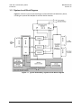
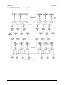
1.1.1 System-Level Block Diagram.................................................................................................... 1–4
iii
CRS-300 1:10 Redundancy Switch
Table of Contents
1.1.2
1.2
MN/CRS300.IOM
Revision 19
CRS-280/280L Functional Schematic ....................................................................................... 1–5
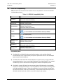
CRS-300 Compatibility ........................................................................................................ 1–6
1.3
Description of CRS-300 Features ......................................................................................... 1–7
1.3.1 Front Panel .............................................................................................................................. 1–7
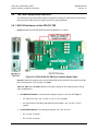
1.3.2 Rear Panel ................................................................................................................................ 1–8
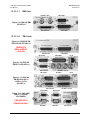
1.3.3 Plug-in Module (Card) Assemblies........................................................................................... 1–9
1.3.3.1
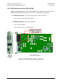
CRS-300 System Controller Card Assembly .................................................................... 1–9
1.3.3.2
Power Supply Card Assemblies ....................................................................................... 1–9
1.3.3.3
Modem Interface Cards ................................................................................................ 1–10
1.3.3.3.1 CDM-625/A, CDM-570/A, CDM-570L/AL, CDM-600/L Interface Cards ................... 1–10
1.3.3.3.1.1 RMI Card ........................................................................................................... 1–11
1.3.3.3.1.2 TMI Cards .......................................................................................................... 1–11
1.3.3.3.2 SLM-5650/5650A, CDM-Qx/QxL, CDM-710G/710GL, CDM-710, CDM-700 Interface
Cards
................................................................................................................................. 1–12
1.3.3.3.2.1 RMI Cards.......................................................................................................... 1–13
1.3.3.3.2.2 TMI Cards .......................................................................................................... 1–14
1.4
Optional CRS-350 ESC Switch ............................................................................................ 1–15
1.5
Summary of Specifications ............................................................................................... 1–17
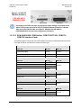
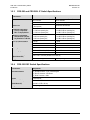
1.5.1 CRS-300 1:10 Redundancy Switch Specifications .................................................................. 1–17
1.5.2 Modem vs. Terrestrial User Data Interface Specifications .................................................... 1–18
1.5.3 CRS-280 and CRS-280L IF Switch Specifications .................................................................... 1–19
1.5.4 CRS-350 ESC Switch Specifications ........................................................................................ 1–19
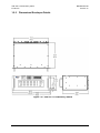
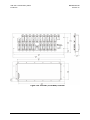
1.5.5 Dimensional Envelope Details ............................................................................................... 1–20
CHAPTER 2.
INSTALLATION ................................................................................................... 2–1
2.1
Unpack and Inspect the Shipment ...................................................................................... 2–1
2.2
Install the Unit Into a Rack Enclosure .................................................................................. 2–2
CHAPTER 3.
SWITCH CONNECTORS AND PINOUTS ................................................................. 3–1
3.1
Cabling Connection Types .................................................................................................. 3–1
3.1.1 Coaxial Cable Connections....................................................................................................... 3–1
3.1.1.1
Type ‘BNC’ ....................................................................................................................... 3–2
3.1.1.2
Type ‘TNC’ ....................................................................................................................... 3–2
3.1.1.3
Type ‘N’ ........................................................................................................................... 3–2
3.1.1.4
Type ‘F’ ............................................................................................................................ 3–2
3.1.1.5
Type ‘SMA’ (Subminiature Version ‘A’)........................................................................... 3–3
3.1.2 D-Subminiature Cable Connections......................................................................................... 3–3
3.1.3 RJ-45, RJ-48 Cable Connections ............................................................................................... 3–3
3.2
CRS-300 User Data Connectors ........................................................................................... 3–4
3.2.1 CRS-230 Controller Connectors ............................................................................................... 3–4
iv
CRS-300 1:10 Redundancy Switch
Table of Contents
MN/CRS300.IOM
Revision 19
3.2.1.1
IF Switch Control Connector, DB-25M ............................................................................ 3–4
3.2.1.2
485 Pass-Through Connector, DB-9F .............................................................................. 3–4
3.2.1.3
Remote Control Connector, DB-9M................................................................................ 3–5
3.2.1.4
System Alarms Connector, DB-25F ................................................................................. 3–6
3.2.2 TMI User Data Connectors ...................................................................................................... 3–7
3.2.2.1
EIA-232/422/V.35 Connector, DB-25F (CRS-316) ........................................................... 3–7
3.2.2.2
EIA-232/422/V.35/LVDS Connector, DB-25F (CRS-320/340) .......................................... 3–8
3.2.2.3
ASI Connectors, BNC (CRS-325) ...................................................................................... 3–9
3.2.2.4
8 kHz IDR Connector, RJ-45F (CRS-330) .......................................................................... 3–9
3.2.2.5
Balanced G.703 Connector, DB-15F (CRS-325/330/340) .............................................. 3–10
3.2.2.6
Unbalanced G.703 Connectors, BNC (CRS-325/330/340) ............................................ 3–11
3.2.2.7
Unbalanced G.703 4-Port Connectors, BNC (CRS-345)................................................. 3–11
3.2.2.8
HSSI Connector, HD-50F (CRS-336/370) ....................................................................... 3–12
3.2.2.9
10/100/1000 Gigabit Ethernet Connector, RJ-45F (CRS-316/336) ............................... 3–13
3.2.2.10 Quad E1 Connectors, RJ-48F (CRS-365) ........................................................................ 3–14
3.2.2.11 Quad E1 Connectors, DB-9F (CRS-365D)....................................................................... 3–15
3.3
CRS-300 Chassis Ground and Power Connections .............................................................. 3–16
3.3.2.2
48V Direct Current (DC) Power Interface ..................................................................... 3–19
CHAPTER 4.
4.1
CABLES AND CONNECTIONS ............................................................................... 4–1
Overview ...........................................................................................................................4–1
4.2
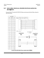
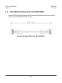
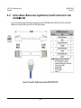
Switch-to-Switch Connections ............................................................................................ 4–4
4.2.1 CRS-300 to CRS-280/280L Connection .................................................................................... 4–4
4.2.2 CRS-300 to CRS-350 Connection.............................................................................................. 4–4
4.2.3 CRS-300 to CRS-350 and CRS-280/280L Connection ............................................................... 4–4
4.3
IF Cable Connections ........................................................................................................ 4–12
4.3.1 IF Cable Connections – Single Transponder (without CRS-280/280L) ................................... 4–12
4.3.2 IF Cable Connections – Multiple Transponder (Using IF Switch)........................................... 4–14
4.4
CDM-625/A Modem Connections ..................................................................................... 4–18
4.4.1 RMI/TMI Limitations and Considerations.............................................................................. 4–18
4.4.2 Carrier-in-Carrier® (CnC) Data Connections ........................................................................... 4–19
4.4.3 Control and Data Connections – CRS-300 to Modem ........................................................... 4–21
4.4.3.1
Control Cabling Requirement (Regardless of Driving Traffic Data Type)...................... 4–21
4.4.3.2
G.703 Balanced / Unbalanced Data Connections ......................................................... 4–22
4.4.3.3
G.703 Quad E1 Data Connections ................................................................................. 4–23
4.4.3.4
ASI Data Connections .................................................................................................... 4–24
4.4.3.5
EIA-422 Data Connections ............................................................................................ 4–25
4.4.3.6
HSSI Data Connections .................................................................................................. 4–26
4.4.3.7
LVDS Data Connections................................................................................................. 4–26
4.4.3.8
Ethernet Data Connections ........................................................................................... 4–26
4.4.3.8.1 Ethernet Data Connection – Wired-thru Method (No Sub-Mux) ............................ 4–27
4.4.3.8.2 Ethernet Data Connection – Wired-around Method (Sub-Mux) ............................. 4–28
4.4.4 Data Connections – CRS-300 to User..................................................................................... 4–33
v
CRS-300 1:10 Redundancy Switch
Table of Contents
MN/CRS300.IOM
Revision 19
4.4.5 Data Connections – CRS-350 Engineering Service Channel (ESC) Switch .............................. 4–33
4.4.5.1
ESC Data Connections – Modems to CRS-350 .............................................................. 4–33
4.4.5.2
ESC Data Connections – CRS-350 to User ..................................................................... 4–33
4.4.6 Operation of the CDM-625/A in CDM-600/L Emulation Mode ............................................. 4–33
4.4.6.1
Preparing the CDM-625/A for Operation in CDM-600/L Emulation Mode .................. 4–34
4.4.6.2
Control and Data Connections – CRS-300 to Modems in CDM-600/L Emulation Mode ......
...................................................................................................................................... 4–34
4.5
CDM-570/A, CDM-570L/AL Modem Connections .............................................................. 4–38
4.5.1 Control and Data Connections – CRS-300 to Modems .......................................................... 4–38
4.5.2 User Data Connections – CRS-300 to User ............................................................................ 4–38
4.6
SLM-5650/5650A Modem Connections ............................................................................. 4–42
4.6.1 RMI/TMI Limitations and Considerations.............................................................................. 4–42
4.6.2 Control Cable Connections – CRS-300 to Modems ............................................................... 4–42
4.6.3 Traffic Data Connections – CRS-300 to Modems................................................................... 4–43
4.6.3.1
Ethernet Traffic Data Connections................................................................................ 4–44
4.6.3.1.1 Ethernet Bridge Mode via the Optional GbE Interface ............................................ 4–44
4.6.3.1.2 Ethernet Bridge Mode via the Optional NP Interface .............................................. 4–44
4.6.4 User Data Connections – CRS-300 to User ............................................................................ 4–44
4.6.5 ESC Data Connections – Modems to CRS-350 ....................................................................... 4–44
4.6.6 User ESC Data Connections – CRS-350 to User ..................................................................... 4–45
4.7
CDM-Qx/QxL Modem Connections ................................................................................... 4–52
4.7.1 RMI/TMI Limitations and Considerations.............................................................................. 4–52
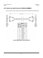
4.7.2 EIA-485 Connections – CRS-300 to Modems ......................................................................... 4–52
4.7.3 Control Y-Cable Connections – CRS-300 to Modems ............................................................ 4–54
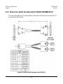
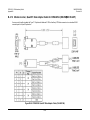
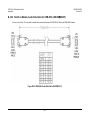
4.7.4 Traffic Data Connections – CRS-300 to Modems................................................................... 4–54
4.7.5 User Data Connections – CRS-300 to User ............................................................................ 4–55
4.8
CDM-710G/710GL Modem Connections............................................................................ 4–62
4.8.1 RMI/TMI Limitations and Considerations.............................................................................. 4–62
4.8.2 Interface Combinations ......................................................................................................... 4–62
4.8.3 Control Cable Connections – CRS-300 to Modems ............................................................... 4–63
4.8.4 Serial Traffic Data Connections – CRS-300 to Modems......................................................... 4–63
4.8.5 Ethernet Traffic Data Connections – CRS-300 to Modems ................................................... 4–63
4.8.6 User Data Connections – CRS-300 to User ............................................................................ 4–64
4.9
CDM-710 Modem Connections ......................................................................................... 4–68
4.9.1 RMI/TMI Limitations and Considerations.............................................................................. 4–68
4.9.2 Interface Combinations ......................................................................................................... 4–68
4.9.3 Control Cable Connections – CRS-300 to Modems ............................................................... 4–69
4.9.4 Serial Traffic Data Connections – CRS-300 to Modems......................................................... 4–69
4.9.5 Ethernet Traffic Data Connections – CRS-300 to Modems ................................................... 4–69
4.9.6 User Data Connections – CRS-300 to User ............................................................................ 4–70
4.10 CDM-700 Modem Connections ......................................................................................... 4–74
4.10.1
RMI/TMI Limitations and Considerations ......................................................................... 4–74
vi
CRS-300 1:10 Redundancy Switch
Table of Contents
MN/CRS300.IOM
Revision 19
4.10.2
Interface Combinations ..................................................................................................... 4–74
4.10.3
Control Cable Connections – CRS-300 to Modems ........................................................... 4–75
4.10.4
Serial Traffic Data Connections – CRS-300 to Modems .................................................... 4–75
4.10.5
Ethernet Traffic Data Connections – CRS-300 to Modems ............................................... 4–76
4.10.5.1 Wired-thru Connections ............................................................................................... 4–76
4.10.5.2 Wired-around Connections........................................................................................... 4–76
4.10.6
User Data Connections – CRS-300 to User ........................................................................ 4–77
4.11 CDM-600/L Modem Connections ...................................................................................... 4–86
4.11.1
Control and Data Connections – CRS-300 to Modems ..................................................... 4–86
4.11.2
User Data Connections – CRS-300 to User ........................................................................ 4–88
4.11.3
ESC Data Connections – Modems to CRS-350................................................................... 4–88
4.11.4
User ESC Data Connections – CRS-350 to User ................................................................. 4–88
CHAPTER 5.
MODEM, RMI/TMI, AND SWITCH CONFIGURATION ............................................ 5–1
5.2
Configure Your Modems .................................................................................................... 5–2
5.2.1 Connect Your Modem Power .................................................................................................. 5–2
5.2.2 Modem Firmware and Hardware Requirements .................................................................... 5–2
5.2.2.1
Update Your Modem Firmware ...................................................................................... 5–3
5.2.3 Configure Your Modem Operation .......................................................................................... 5–3
5.2.4 Configure Your Modems for 1:N Redundancy ........................................................................ 5–3
5.2.4.1
Configure Switch-to-CDM-625/A 1:N Redundancy ........................................................ 5–3
5.2.4.1.1 Configure CDM-625/A 1:N Redundancy for Carrier-in-Carrier® ................................ 5–4
5.2.4.2
Configure Switch-to-CDM-570/A, CDM-570L/AL, CDM-600/L 1:N Redundancy ............ 5–5
5.2.4.3
Configure Switch-to-SLM-5650/5650A 1:N Redundancy ............................................... 5–5
5.2.4.4
Configure Switch-to-CDM-Qx/QxL 1:N Redundancy ...................................................... 5–7
5.2.4.5
Configure Switch-to-CDM-710G/710GL, CDM-710, CDM-700 1:N Redundancy .......... 5–10
5.3
RMI Card Configuration Reference ................................................................................... 5–11
5.4
TMI Card Configuration Reference .................................................................................... 5–12
5.4.1 EIA-530 Interfaces via the CRS-316 TMI ................................................................................ 5–12
5.4.2 EIA-232/-422, V.35 Interfaces via the CRS-320 and CRS-340 TMIs ....................................... 5–15
5.4.3 HSSI Interfaces via the CRS-336 TMI ..................................................................................... 5–17
5.4.4 HSSI Interface via the CRS-370 TMI ....................................................................................... 5–19
5.5
Configure the CRS-300 Switch........................................................................................... 5–20
5.5.1 Connect the Switch Power .................................................................................................... 5–20
5.5.2 About the Switch Fuses ......................................................................................................... 5–20
5.6
Update the CRS-300 Switch Firmware ............................................................................... 5–21
5.6.1.1
About Firmware Files, Naming, Versions, and Archive Formats .................................. 5–21
5.6.1.2
Switch Firmware Update Procedure ............................................................................. 5–22
5.6.1.2.1 Getting Started: Prepare for the Firmware Download ............................................ 5–22
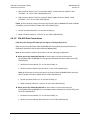
5.6.1.2.2 Download and Extract the Firmware Update .......................................................... 5–23
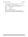
5.6.1.2.3 Execute the CCCFLASH Upload Utility Application .................................................. 5–25
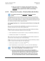
5.6.2 Configure the CRS-300 Switch Operation.............................................................................. 5–25
vii
CRS-300 1:10 Redundancy Switch
Table of Contents
MN/CRS300.IOM
Revision 19
5.6.2.1
Activate the Traffic Modems ........................................................................................ 5–25
5.6.2.2
Verify Each Active Modem Connection ........................................................................ 5–26
5.6.2.3
Set the Switch Operation Mode ................................................................................... 5–27
5.6.2.4
Set the Holdoff Period .................................................................................................. 5–27
5.6.2.5
Set the Backup Holdoff Period ...................................................................................... 5–28
5.6.2.5.1 Set the Restore Holdoff Period ................................................................................ 5–28
5.6.2.6
Set the Alarm Masks ..................................................................................................... 5–29
CHAPTER 6.
FRONT PANEL OPERATION ................................................................................. 6–1
6.1
Overview ...........................................................................................................................6–1
6.1.1 Front Panel LED Indicators ...................................................................................................... 6–2
6.1.1.1
Switch Status LED Indicators ........................................................................................... 6–2
6.1.1.2
Modem Status LED Indicators......................................................................................... 6–3
6.1.2 Front Panel Keypad.................................................................................................................. 6–4
6.1.3 Front Panel Vacuum Fluorescent Display (VFD) ...................................................................... 6–5
6.1.3.1
Opening Screen ............................................................................................................... 6–5
6.1.3.2
Menu Structure ............................................................................................................... 6–6
6.2
Front Panel Operation........................................................................................................ 6–7
6.2.1 SELECT: (Top-Level) Menu ....................................................................................................... 6–7
6.2.2 SELECT: CONFIG (Configuration) ............................................................................................. 6–7
6.2.2.1
CONFIG: MANUAL ........................................................................................................... 6–8
6.2.2.2
CONFIG: AUTO (AUTO-OFF or AUTO-ON) ....................................................................... 6–8
6.2.2.3
CONFIG: OPTIONS ........................................................................................................... 6–9
6.2.2.3.1 CONFIG: OPTIONS PRIORITY ................................................................................. 6–9
6.2.2.3.2 CONFIG: OPTIONS HOLDOFFS ............................................................................... 6–9
6.2.2.3.3 CONFIG: OPTIONS ALARM-MASK ........................................................................ 6–10
6.2.2.4
CONFIG: REMOTE.......................................................................................................... 6–11
6.2.2.4.1 CONFIG: REMOTE LOCAL..................................................................................... 6–11
6.2.2.4.2 CONFIG: REMOTE REMOTE ................................................................................. 6–11
6.2.2.5
CONFIG: ACTIVE (Activate Modems) ............................................................................ 6–12
6.2.3 SELECT: INFO (Information) ................................................................................................... 6–14
6.2.3.1
INFO: S/N ...................................................................................................................... 6–14
6.2.3.2
INFO: ID ......................................................................................................................... 6–14
6.2.3.3
INFO: SETUP .................................................................................................................. 6–14
6.2.3.4
INFO: IF-SWITCH ........................................................................................................... 6–14
6.2.3.5
INFO: REMCONT (Remote Control Info) ....................................................................... 6–15
6.2.3.6
INFO: MASK (Alarm Mask Info) ..................................................................................... 6–15
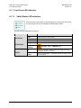
6.2.4 SELECT: MONITOR ................................................................................................................. 6–15
6.2.4.1
MONITOR: STATUS........................................................................................................ 6–15
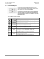
6.2.4.2
MONITOR: SW-ALARM.................................................................................................. 6–16
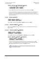
6.2.4.3
MONITOR: STORED-EVENTS ......................................................................................... 6–19
6.2.4.3.1 MONITOR: STORED-EVENTS VIEW ...................................................................... 6–19
6.2.4.3.2 MONITOR: STORED-EVENTS CLEAR-ALL.............................................................. 6–19
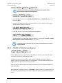
6.2.4.4
MONITOR: COMMS (Communications State) ............................................................... 6–19
6.2.4.5
MONITOR: IO ................................................................................................................ 6–20
6.2.5 SELECT: STORE/LD (Store or Load Configuration) ................................................................. 6–20
viii
CRS-300 1:10 Redundancy Switch
Table of Contents
MN/CRS300.IOM
Revision 19
6.2.5.1
STORE/LD: STORE.......................................................................................................... 6–20
6.2.5.2
STORE/LD: LOAD ........................................................................................................... 6–21
6.2.6 SELECT: UTILITY...................................................................................................................... 6–21
6.2.6.1
UTILITY: SET- RTC (Set Real-Time Clock) ....................................................................... 6–21
6.2.6.2
UTILITY: DISPLAY (Display Brightness) .......................................................................... 6–21
6.2.6.3
UTILITY: SWITCH-ID ....................................................................................................... 6–22
6.2.6.4
UTILITY: TEST................................................................................................................. 6–22
6.2.6.5
UTILITY: RELAY .............................................................................................................. 6–22
CHAPTER 7.
SERIAL-BASED REMOTE PRODUCT MANAGEMENT .............................................. 7–1
7.1
Overview ...........................................................................................................................7–1
7.2
EIA-485 ..............................................................................................................................7–1
7.3
EIA-232 ..............................................................................................................................7–2
7.4
Rules for Remote Serial Communications with the CRS-300................................................. 7–2
7.5
Basic Protocol ....................................................................................................................7–3
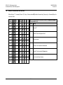
7.5.1 Packet Structure ...................................................................................................................... 7–4
7.5.1.1
Start of Packet................................................................................................................. 7–4
7.5.1.2
Target Address ................................................................................................................ 7–5
7.5.1.3
Address Delimiter ........................................................................................................... 7–6
7.5.1.4
Instruction Code.............................................................................................................. 7–6
7.5.1.5
Instruction Code Qualifier............................................................................................... 7–6
7.5.1.6
Optional Message Arguments ........................................................................................ 7–7
7.5.1.7
End Of Packet .................................................................................................................. 7–7
7.6
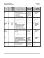
Remote Commands and Queries ........................................................................................ 7–8
APPENDIX A.
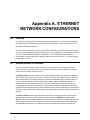
ETHERNET NETWORK CONFIGURATIONS ........................................................... A–1
A.1
Overview .......................................................................................................................... A–1
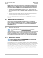
A.2
Ethernet Routers vs. Switches ........................................................................................... A–1
A.3
Ethernet Configuration Examples ...................................................................................... A–2
A.3.1 Ethernet Network Overview ....................................................................................................A–2
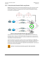
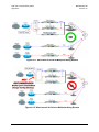
A.3.2 Ethernet Redundancy with CRS-300........................................................................................A–3
A.3.2.1 Wired-thru Connection ...................................................................................................A–3
A.3.2.2 Wired-around Connection ..............................................................................................A–3
A.3.4 Hub-to-Hub with Standard Traffic using Routers ....................................................................A–4
A.3.5 Hub-to-Hub with Standard Traffic using Switches ..................................................................A–6
A.3.6 Hub-to-Remotes with Standard Traffic using Routers or Switches .........................................A–8
A.3.7 Hub-to-Remotes, Split-path Traffic using Routers (Point-to-Multipoint)..............................A–10
A.3.8 Hub-to-Remotes, Split-path Traffic using Switches (Point-to-Multipoint) ............................A–12
ix
CRS-300 1:10 Redundancy Switch
Table of Contents
APPENDIX B.
B.1
MN/CRS300.IOM
Revision 19
CABLE DRAWINGS .............................................................................................. B-1
Overview ........................................................................................................................... B-1
B.2
User / Utility Cables ........................................................................................................... B-1
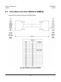
B.2.1 Switch-to-User, EIA-530-to-EIA-422/-449 Data Conversion Cable (DB-25MDB-37F)...........B-2
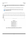
B.2.2 Switch-to-User, EIA-530-to-V.35 Data Conversion Cable (DB-25MWinchester 34F) ...........B-3
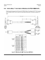
B.2.3 Switch-to-User, Monitor and Control (M&C) Cable (DB-9FDB-9F).......................................B-4
B.3
Control Cables ................................................................................................................... B-5
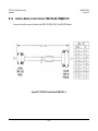
B.3.1 Switch-to-Modem, Control Cable for CDM-625/A (HD-15MDB-9M) ...................................B-6
B.3.2 Switch-to-Modem, Control Cable for SLM-5650/5650A (HD-15MHD-15M) ........................B-7
B.3.3 Switch-to-Modem, Optional ‘Y’ Control Cable for SLM-5650/5650A (HD-15MHD-15M,
DB-9F) ..................................................................................................................................................B-8
B.3.4 Switch-to-Modem, Standard EIA-485 Multi-Drop Shielded Cable for CDM-Qx/QxL (15X DB-9F)
..................................................................................................................................................B-9
B.3.5 EIA-485 Cable Termination for CDM-Qx/QxL Multi-Drop Cables (DB-9M) ........................... B-10
B.3.6 Switch-to-Modem, EIA-485 Null Modem Cable for CDM-Qx/QxL (DB-9MDB-9M) ........... B-11
B.3.7 Modem-to-Modem, Optional EIA-485 Multi-Drop Ribbon Cable for CDM-Qx/QxL (15X DB-9F) .
............................................................................................................................................... B-12
B.3.8 Switch-to-Modem, ‘Y’ Control Cable for CDM-Qx/QxL with CnC (HD-15M2X DB-15F)... B-13
B.3.9 Switch-to-Modem, Control Cable for CDM-7XX (HD-15MDB-15F) ................................... B-14
B.4
Control / IF / Data Cables & Accessories ........................................................................... B-15
B.4.1 Switch-to-Modem / Switch-to-User, EIA-232/422, EIA-530 Control and Data Cable
(DB-25MDB-25F) ............................................................................................................................. B-18
B.4.2 Switch-to-Modem / Modem-to-User, IF Cable (BNC 50Ω Male)........................................... B-19
B.4.3 Switch-to-Modem, ASI / Balanced G.703 / IF Cable (BNC 75Ω Male)................................... B-20
B.4.4 Modem-to-Modem, Multi-Drop CnC® Plus Shielded Data Cable for CDM-625/A (11X DB-9M) ...
............................................................................................................................................... B-21
B.4.5 Modem-to-User, Ethernet Data Cable for CDM-625/A (RJ-45MHD-50M) ........................ B-22
B.4.6 Switch-to-Modem, Balanced G.703 Data Cable for CDM-625/A (DB-15FDB-15M) .......... B-23
B.4.7 Switch-to-Modem / Modem-to-User, Gigabit Ethernet, Quad E1 RJ-48 Connector Cable
(RJ-48MRJ-48M).............................................................................................................................. B-24
B.4.8 Switch-to-Modem, HSSI Data Cable (HD-50MHD-50M) .................................................... B-25
B.4.9 Switch-to-Modem, Quad E1 Data ‘Y’ Cable for CDM-625/A (DB-15F2X DB-9M) .............. B-26
B.4.10
Modem-to-User, Quad E1 Data Cable for CDM-625/A (DB-9MDB-9F) ......................... B-27
B.4.11
Modem-to-User, Quad E1 Data Adapter Cable for CDM-625/A (DB-9M2X DB-15F) .... B-28
B.4.12
Modem-to-User, Quad E1 Data Adapter Cable for CDM-625/A (DB-9M2X RJ-48F) ..... B-29
B.4.13
Modem-to-Switch (CDM-625/A to CRS-350), Overhead Data Cable (DB-44M,
DB-9MDB-9F, DB-25M, DB-15F) ..................................................................................................... B-30
B.4.14
Switch-to-User / Switch-to-Modem, Balanced G.703 Data Cable (DB-15MDB-15F) .... B-31
B.4.15
Switch-to-Modem / Switch-to-User, Balanced G.703 Data Cable for CDM-570/A,
CDM-570L/AL (DB-15MDB-15F) ..................................................................................................... B-32
B.4.16
Modem-to-User, Optional T1/E1 Adapter for CDM-570/A, CDM-570L/AL, CDM-600/L
(DB-15MRJ-48F) .............................................................................................................................. B-33
B.4.17
Switch-to-Modem, Quad E1 Data Cable for CDM-Qx/QxL (DB-15F4X RJ-45M)............ B-34
B.4.18
Switch-to-Modem, G.703 Data Cable for CDM-700 (DB-9F8X BNC 75Ω Male) ............ B-35
x
CRS-300 1:10 Redundancy Switch
Table of Contents
B.4.19
B.4.20
APPENDIX C.
MN/CRS300.IOM
Revision 19
Switch-to-Modem, G.703 Data Cable for CDM-700 (DB-15F8X BNC 75Ω Male) .......... B-36
Switch-to-Modem, Audio Data Cable for CDM-600/L (DB-9MDB-9F) .......................... B-37
ADDRESSING SCHEME INFORMATION ................................................................C–1
C.1
Addressing Overview .........................................................................................................C–1
C.1.1 Switch Addresses ..................................................................................................................... C–2
C.1.2 Modem and Transceiver Addresses ........................................................................................ C–2
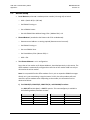
C.2
Modem Setup .................................................................................................................. C–11
C.3
Transceiver Setup ............................................................................................................ C–12
C.4
M&C Applications ............................................................................................................ C–13
TABLES
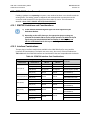
Table 1-1. CRS-300 Compatibility Table .................................................................................................... 1–6
Table 3-1. 485 Pass-Through User Data Connector .................................................................................. 3–4
Table 3-2. Remote Control Connector ...................................................................................................... 3–5
Table 3-3. System Alarms Connector ........................................................................................................ 3–6
Table 3-4. EIA-232/422/V.35 Connector ................................................................................................... 3–7
Table 3-5. EIA-232/422/V.35/LVDS Connector ......................................................................................... 3–8
Table 3-6. ASI Connectors ......................................................................................................................... 3–9
Table 3-7. 8 kHz – IDR ESC Connector....................................................................................................... 3–9
Table 3-8. Balanced G.703 Connector .................................................................................................... 3–10
Table 3-9. Unbalanced G.703 Connectors .............................................................................................. 3–11
Table 3-10. Unbalanced G.703 Connectors ............................................................................................ 3–11
Table 3-11. HSSI Connector..................................................................................................................... 3–12
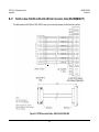
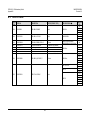
Table 3-12. 10/100/1000 Gigabit Ethernet Connector Pinouts .............................................................. 3–13
Table 3-13. Quad E1 Connector Pinouts (Typical Ports 1 through 4) ..................................................... 3–14
Table 3-14. Quad E1 Connector Pair Pinouts .......................................................................................... 3–15
Table 4-1. CDM-625/A Cable Usage (RMI/TMI) ...................................................................................... 4–21
Table 4-2. CDM-710G/710GL Interface Card Combinations ................................................................... 4–62
Table 4-3. CDM-710 Interface Card Combinations ................................................................................. 4–68
Table 4-4. CDM-700 Interface Card Combinations ................................................................................. 4–74
Table 5-1. RMI “JMP1” Jumper Settings (As Shipped) ............................................................................ 5–11
Table 5-2. CRS-316 “JP1” Jumper Settings .............................................................................................. 5–13
Table 5-3. CRS-316 “JP2” Jumper Settings .............................................................................................. 5–14
Table 5-4. CRS-316 “JP3” through “JP6” Jumper Settings ...................................................................... 5–14
Table 5-5. CRS-320/CRS-340 Jumper Settings ........................................................................................ 5–16
Table 5-6. CRS-336 Jumper “JP1” Settings .............................................................................................. 5–18
Table 5-7. CRS-336 Jumper “JP2” Settings .............................................................................................. 5–18
Table 5-8. CRS-370 Jumper “J2” Settings ................................................................................................ 5–19
xi
CRS-300 1:10 Redundancy Switch
Table of Contents
MN/CRS300.IOM
Revision 19
FIGURES
Figure 1-1. Typical Redundancy System-Level Block Diagram .................................................................. 1–4
Figure 1-2. CRS-280/280L IF Switch Functional Schematic ....................................................................... 1–5
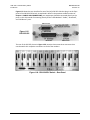
Figure 1-3. CRS-300 Front Panel Features ................................................................................................ 1–7
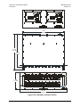
Figure 1-4. CRS-300 Rear Panel – Configuration Example ........................................................................ 1–8
Figure 1-5. CRS-230 System Controller (AS/0377) .................................................................................... 1–9
Figure 1-6. CRS-240 AC Power Supply (AS/0376) ..................................................................................... 1–9
Figure 1-7. CRS-250 DC Power Supply (PL/10458-1) ................................................................................ 1–9
Figure 1-8. CRS-310 RMI (PL/9579-1) ..................................................................................................... 1–11
Figure 1-9. CRS-320 TMI EIA-232/-422 (PL/9581-1) ............................................................................... 1–11
Figure 1-10. CRS-330 TMI G.703 (PL/9033-1) ......................................................................................... 1–11
Figure 1-11. CRS-340 TMI EIA-232/-422 or LVDS or G.703 ..................................................................... 1–11
Figure 1-12. CRS-365D TMI E1 (1-4 ports) (PL/12985-2) ........................................................................ 1–11
Figure 1-13. CRS-370 TMI HSSI (PL/9034-1)............................................................................................ 1–12
Figure 1-14. CRS-305 RMI (PL/11494-1) ................................................................................................. 1–13
Figure 1-15. CRS-306 RMI (PL/11494-2) ................................................................................................. 1–13
Figure 1-16. CRS-307 RMI (PL/11494-3) ................................................................................................. 1–13
Figure 1-17. CRS-315 TMI........................................................................................................................ 1–14
Figure 1-18. CRS-316 TMI RS422 or GigE (PL/12498-1) .......................................................................... 1–14
Figure 1-19. CRS-325 TMI G.703 or ASI (PL/11492-1) ............................................................................. 1–14
Figure 1-20. CRS-315 TMI........................................................................................................................ 1–14
Figure 1-21. CRS-336 TMI HSSI or GigE (PL/12499-1) ............................................................................. 1–14
Figure 1-22. CRS-345 TMI G.703 (4 ports) (PL/11495-1) ........................................................................ 1–15
Figure 1-23. CRS-365 TMI E1 (1-4 ports) (PL/12985-1) ........................................................................... 1–15
Figure 1-24. CRS-350 ESC Switch – Front Panel ...................................................................................... 1–15
Figure 1-25. CRS-355 UDI ........................................................................................................................ 1–16
Figure 1-26. CRS-350 ESC Switch – Rear Panel ....................................................................................... 1–16
Figure 1-27. CRS-300 1:1 Redundancy Switch ........................................................................................ 1–20
Figure 1-28. CRS-280 (70/140 MHz) IF Switch ........................................................................................ 1–21
Figure 1-29. CRS-280L (L-Band) IF Switch ............................................................................................... 1–22
Figure 1-30. CRS-350 ESC Switch ............................................................................................................ 1–23
Figure 2-1. Unpacking and Inspecting the Shipment ................................................................................ 2–1
Figure 2-2. Typical Rack Mounting Configuration..................................................................................... 2–4
Figure 3-1. Coaxial Connector Examples................................................................................................... 3–1
Figure 3-2. D-Subminiature Connector Examples ..................................................................................... 3–3
Figure 3-3. CRS-300 Chassis Ground Interfaces ...................................................................................... 3–16
Figure 3-4. CRS-300 Chassis Power Supply Interfaces ............................................................................ 3–17
Figure 3-5. Chassis AC Power Interface (CRS-240 Power Supply Module) ............................................. 3–17
Figure 3-6. Apply AC Power .................................................................................................................... 3–18
Figure 3-7. Replace the AC Fuses ............................................................................................................ 3–18
Figure 3-8. Chassis DC Power Interface (CRS-250 DC Power Supply Module)........................................ 3–19
Figure 3-9. Apply DC Power .................................................................................................................... 3–19
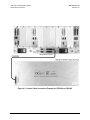
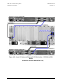
Figure 4-1. Control Cable Connection Example for CRS-300 to CRS-280.................................................. 4–5
Figure 4-2. Control Cable Connection Example for CRS-300 to CRS-280L ................................................ 4–6
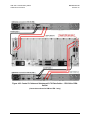
Figure 4-3. Control Cable Connection Example for CRS-300 to CRS-350.................................................. 4–7
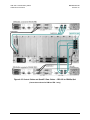
Figure 4-4. Control Cable Connection Example for CRS-300 to CRS-350 to CRS-280 ............................... 4–8
xii
CRS-300 1:10 Redundancy Switch
Table of Contents
MN/CRS300.IOM
Revision 19
Figure 4-5. Control Cable Connection Example for CRS-300 to CRS-350 to CRS-280L ............................. 4–9
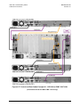
Figure 4-6. IF Cabling Example – Single Transponder Configuration ...................................................... 4–13
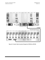
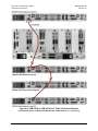
Figure 4-7. IF Cabling Example – Multiple Transponder Configuration .................................................. 4–15
Figure 4-8. CDM-625/A to CDM-625/A CnC® Cable Connection Example .............................................. 4–20
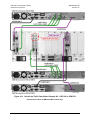
Figure 4-9. CRS-300 to CDM-625/A Cable Connection Example – G.703-driven Configuration............. 4–29
Figure 4-10. CRS-300 to CDM-625/A Cable Connection Example – G.703-driven Configuration........... 4–30
Figure 4-11. CRS-300 to CDM-625/A Cable Connection Example – Quad E1-driven Configuration ...... 4–31
Figure 4-12. CRS-300 to CDM-625/A Cable Connection Example – Sub-Mux TMIs 3 & 9 ...................... 4–32
Figure 4-13. Cabling Example for CDM-625/A to CRS-350 ..................................................................... 4–35
Figure 4-14. Data Cables – CRS-300 to CDM-625/A (CDM-600/L Emulation Mode) .............................. 4–36
Figure 4-15. Data Cable Connection Example – CRS-300 to CDM-570/A or CDM-570L/AL ................... 4–39
Figure 4-16. Control and Data Cables Example #1 – CRS-300 to SLM-5650/5650A ............................... 4–46
Figure 4-17. Control and Data Cables Example #2 – CRS-300 to SLM-5650/5650A ............................... 4–47
Figure 4-18. Control and Data Cables Example #3 – CRS-300 to SLM-5650/5650A ............................... 4–48
Figure 4-19. Cabling Example for SLM-5650/5650A to CRS-350 ............................................................ 4–49
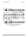
Figure 4-20. EIA-485 Multi-drop Cabling Example – CRS-300 to CDM-Qx/QxL ...................................... 4–53
Figure 4-21. ‘Y’ Control Cables and EIA-530/-232 Data Cables – CRS-300 to CDM-Qx/QxL ................... 4–56
Figure 4-22. ‘Y’ Control Cables and Balanced G.703 Data Cables – CRS-300 to CDM-Qx/QxL ............... 4–57
Figure 4-23. ‘Y’ Control Cables and Unbalanced G.703 Data Cables – CRS-300 to CDM-Qx/QxL .......... 4–58
Figure 4-24. Control Cables and HSSI Data Cables – CRS-300 to CDM-Qx/QxL ...................................... 4–59
Figure 4-25. Control Cables and Quad E1 Data Cables – CRS-300 to CDM-Qx/QxL ............................... 4–60
Figure 4-26. Control and Data Cables Example #1 – CRS-300 to CDM-710G/710GL.............................. 4–64
Figure 4-27. Control and Data Cables Example #2 – CRS-300 to CDM-710G/710GL.............................. 4–65
Figure 4-28. Control and Data Cables Example #1 – CRS-300 to CDM-710 ............................................ 4–70
Figure 4-29. Control and Data Cables Example #2 – CRS-300 to CDM-710 ............................................ 4–71
Figure 4-30. Control and Traffic Data Cables Example #1 – CRS-300 to CDM-700 ................................. 4–78
Figure 4-31. Control and Traffic Data Cables Example #2 – CRS-300 to CDM-700 ................................ 4–79
Figure 4-32. CDM-700 IP Connections – Wired-thru Example #1........................................................... 4–80
Figure 4-33. CDM-700 IP Connections – Wired-thru Example #2........................................................... 4–81
Figure 4-34. CDM-700 IP Connections – Wired-around Example #1 ...................................................... 4–82
Figure 4-35. CDM-700 IP Connections – Wired-around Example #2 ...................................................... 4–83
Figure 4-36. Data Cable Connection Example – CRS-300 to CDM-600/L ................................................ 4–87
Figure 4-37. Cabling Example for CDM-600/L to CRS-350 ...................................................................... 4–89
Figure 5-1. CDM-Qx/QxL Serial Communication Configuration Example ................................................. 5–7
Figure 5-2. CDM-Qx/QxL / CRS-300 EIA-485 Scheme ............................................................................... 5–9
Figure 5-3. CEFD P/N PC/11494x RMI PCB (CRS-307 shown) ................................................................. 5–11
Figure 5-4. CRS-316 EIA-530 TMI Card (Jumpers Shown Open) ............................................................. 5–12
Figure 5-5. CRS-316 “JP1” through “JP6” Jumper Detail (As Shipped) ................................................... 5–13
Figure 5-6. CRS-320 EIA-232/EIA-422 TMI Card (Jumpers Shown Open) ............................................... 5–15
Figure 5-7. CRS-340 EIA-232/-422/G.703 TMI Card (Jumpers Shown Open) ......................................... 5–15
Figure 5-8. CRS-336 HSSI or Ethernet TMI Card...................................................................................... 5–17
Figure 5-9. CRS-336 “JP1” and “JP2” Jumper Detail (As Shipped) .......................................................... 5–18
Figure 5-10. CRS-370 HSSI to LVDS TMI Card (Jumper Shown Open) ..................................................... 5–19
Figure 6-1. CRS-300 Front Panel Features ................................................................................................ 6–1
Figure 6-2. CRS-300 Menu Tree ................................................................................................................ 6–6
Figure A-1. Networking Loop With Switches ............................................................................................ A–2
Figure A-2. Hub-to-Hub With Standard Traffic Using Routers .................................................................. A–4
Figure A-3. Wired-thru for Hub-to-Hub With Standard Traffic Using Routers ......................................... A–5
xiii
CRS-300 1:10 Redundancy Switch
Table of Contents
MN/CRS300.IOM
Revision 19
Figure A-4. Wired-around For Hub-to-Hub With Standard Traffic Using Routers .................................... A–5
Figure A-5. Networking Loop Example...................................................................................................... A–6
Figure A-6. Networking Loop Example (Simplified) .................................................................................. A–6
Figure A-7. Hub-to-Remotes With Standard Traffic Using Routers or Switches....................................... A–8
Figure A-8. Wired-thru for Hub-to-Remotes With Standard Traffic Using Routers or Switches .............. A–9
Figure A-9. Wired-around for Hub-to-Remotes With Standard Traffic Using Routers or Switches ......... A–9
Figure A-10. Point-to-Multipoint Using Routers ..................................................................................... A–10
Figure A-11. Wired-thru for Point-to-Multipoint Using Routers ............................................................ A–11
Figure A-12. Wired-around for Point-to-Multipoint Using Routers........................................................ A–11
Figure A-13. Point-to-Multipoint Using Switches ................................................................................... A–12
Figure A-14. Wired-thru, Hub-to-Remotes, Split-path Traffic Using Switches (Point-to-Multipoint) .... A–13
Figure A-15. Wired-around, Hub-to-Remotes, Split-path Traffic Using Switches (Point-to-Multipoint)........
........................................................................................................................................................ A–13
Figure B-1. DCE Conversion Cable – EIA-530 to EIA-422/-449...................................................................B-2
Figure B-2. DCE Conversion Cable – EIA-530-to-V.35 ................................................................................B-3
Figure B-3. Switch and Modem M&C Cable...............................................................................................B-4
Figure B-4. CDM-625/A Control Cable (CA-0000069) ................................................................................B-6
Figure B-5. SLM-5650/5650A Control Cable (CA/WR12136-1) ..................................................................B-7
Figure B-6. SLM-5650/5650A ‘Y’ Control Cable (CA/WR12842-6) .............................................................B-8
Figure B-7. CDM-Qx/QxL Standard EIA-485 Multi-Drop Shielded Cable (CA/WR11417-1) .......................B-9
Figure B-8. CDM-Qx/QxL EIA-485 Cable Termination (CA/WR11418-1) .................................................B-10
Figure B-9. CDM-Qx/QxL EIA-485 Null Modem Cable (CA/WR11419-1) .................................................B-11
Figure B-10. CDM-Qx/QxL Optional EIA-485 Multi-Drop Ribbon Cable (CA/RB11423-1) .......................B-12
Figure B-11. CDM-Qx/QxL with CnC ‘Y’ Control Cable (CA/WR12069-1) .............................................B-13
Figure B-12. CDM-7XX Control Cable (CA/WR12361-1) ..........................................................................B-14
Figure B-13. EIA-232/422, EIA-530 Control and Data Cable (CA/WR0066) .............................................B-18
Figure B-14. IF Cable, BNC 50Ω for CRS-280 (70/140 MHz) IF Switch (PL/0946-2) .................................B-19
Figure B-15. ASI / Balanced G.703 / IF Cable, BNC 75Ω (PL/0813-8) .......................................................B-20
Figure B-16. Multi-Drop CnC® Plus Shielded Data Cable for CDM-625/A (CA-0000275) ........................B-21
Figure B-17. Ethernet Data Cable for CDM-625/A (CA-0000121) ............................................................B-22
Figure B-18. CDM-625/A Bal G.703 Data Cable (CA-0000072) ................................................................B-23
Figure B-19. Quad E1 / GigE Connector Cable (PP/CAT5FF7FTGY) ..........................................................B-24
Figure B-20. HSSI Data Cable (CA/WR9189-6) .........................................................................................B-25
Figure B-21. CDM-625/A Quad E1 Data ‘Y’ Cable (CA-0000073) .............................................................B-26
Figure B-22. CDM-625/A Quad E1 Data Cable (CA-0000136) ..................................................................B-27
Figure B-23. CDM-625/A Quad E1 Data Adapter Cable (CA-0000163) ....................................................B-28
Figure B-24. CDM-625/A Quad E1 Data Adapter Cable (CA-0000164) ....................................................B-29
Figure B-25. CDM-625/A to CRS-350 Multi-purpose Cable (CA-0000074) ..............................................B-30
Figure B-26. Balanced G.703 Data Cable (CA/WR9038-6) .......................................................................B-31
Figure B-27. CDM-570/A, CDM-570L/AL Balanced G.703 Data Cable (CA/WR11999-6) .........................B-32
Figure B-28. Optional T1/E1 Adapter (CN-0000268) ...............................................................................B-33
Figure B-29. CDM-Qx/QxL Quad E1 Data Cable (CA/WR13018-1)...........................................................B-34
Figure B-30. CDM-700 G.703 Data Cable (CA/RF12278-1) ......................................................................B-35
Figure B-31. CDM-700 G.703 Data Cable (CA/RF12279-1) ......................................................................B-36
Figure B-32. CDM-600/L Audio Data Cable (CA/WR9932-1) ...................................................................B-37
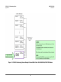
Figure C-1. CRS-300 Addressing Scheme Example: External EIA-232 with CDM-625/A, -570/A, -570L/AL,
-600/L Modems ................................................................................................................................ C–3
xiv
CRS-300 1:10 Redundancy Switch
Table of Contents
MN/CRS300.IOM
Revision 19
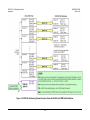
Figure C-2. CRS-300 Addressing Scheme Example: External EIA-485 with CDM-625/A, -570/A, -570L/AL,
-600/L Modems ................................................................................................................................ C–4
Figure C-3. CRS-300 Addressing Scheme Example: External EIA-232 with SLM-5650/5650A, CDM-7XX
Modems ........................................................................................................................................... C–5
Figure C-4. CRS-300 Addressing Scheme Example: External EIA-485 with SLM-5650/5650A, CDM-7XX
Modems ........................................................................................................................................... C–6
Figure C-5. CRS-300 Addressing Scheme Example: External EIA-232 with CDM-Qx/QxL Modems ......... C–7
Figure C-6. CRS-300 Addressing Scheme Example: External EIA-485 with CDM-Qx/QxL Modems ......... C–8
Figure C-7. CRS-300 Addressing Scheme Example: External EIA-485 with CDM-Qx/QxL Modems, EDMAC
Hub-to-Hub....................................................................................................................................... C–9
xv
CRS-300 1:10 Redundancy Switch
Table of Contents
MN/CRS300.IOM
Revision 19
BLANK PAGE
xvi
PREFACE
About this Manual
This manual provides installation and operation information for the Comtech EF Data CRS-300
1:10 Redundancy Switch. This document is intended for anyone who installs or operates the
CRS-300.
Related Documents
•
Comtech EF Data CDM-625A Advanced Satellite Modem Installation and Operation Manual
(CEFD P/N MN-CDM625A)
•
Comtech EF Data CDM-625 Advanced Satellite Modem Installation and Operation Manual
(CEFD P/N MN-CDM625)
•
Comtech EF Data CDM-570A/CDM-570AL/CDMR-570AL Satellite Modem Installation and
Operation Manual (CEFD P/N MN-CDM570A)
•
Comtech EF Data CDM-570/CDM-570L/CDMR-570L Satellite Modem Installation and
Operation Manual (CEFD P/N MN/CDM570L.IOM)
•
Comtech EF Data SLM-5650A Satellite Modem Installation and Operation Manual (CEFD P/N
MN-SLM5650A)
•
Comtech EF Data SLM-5650 Satellite Modem Installation and Operation Manual (CEFD P/N
MN/SLM5650.IOM)
•
Comtech EF Data CDM-Qx/QxL Multi-Channel Satellite Modem Installation and Operation
Manual (CEFD P/N MN/CDMQX.IOM)
•
Comtech EF Data CDM-710G/710GL High-Speed Satellite Modem Installation and Operation
Manual (CEFD P/N MN-CDM710G)
•
Comtech EF Data CDM-710 Broadcast Satellite Modem Installation and Operation Manual
(CEFD P/N MN/CDM710.IOM)
xvii
CRS-300 1:10 Redundancy Switch
Preface
MN/CRS300.IOM
Revision 19
•
Comtech EF Data CDM-700 High-Speed Satellite Modem Installation and Operation Manual
(CEFD P/N MN/CDM700.IOM)
•
Comtech EF Data CDM-600/600L Open Network Satellite Modem Installation and Operation
Manual (CEFD P/N MN/CDM600L.IOM)
•
Comtech EF Data CRS-280L 1:N Redundancy Switch Installation and Operation Manual (CEFD
P/N MN/CRS280L.IOM)
Conventions and References
Patents and Trademarks
See all of Comtech EF Data's Patents and Patents Pending at http://patents.comtechefdata.com.
Comtech EF Data acknowledges that all trademarks are the property of the trademark owners.
Warnings, Cautions and Notes
A WARNING INFORMS YOU ABOUT A POSSIBLE HAZARD THAT MAY CAUSE DEATH
OR SERIOUS INJURY.
A CAUTION informs you about a possible hazard that MAY CAUSE INJURY or
PROPERTY DAMAGE.
A NOTE gives you important information about a task or the equipment.
A REFERENCE directs you to additional information about a task or the equipment.
Examples of Multi-Hazard Notices
xviii
CRS-300 1:10 Redundancy Switch
Preface
MN/CRS300.IOM
Revision 19
Recommended Standard Designations
The Electronic Industries Association (EIA) designations supersede the Recommended Standard
(RS) designations. References to the old designations may be shown when depicting actual text
(e.g., RS-232) displayed on Web Server pages, serial remote interfaces, Telnet Command Line
Interfaces (CLIs), or unit rear panels. All other references in the manual refer to EIA
designations.
CAUTION – You should carefully review the following information.
Safety and Compliance
Electrical Safety and Compliance
The unit complies with the EN 60950 Safety of Information Technology Equipment (Including
Electrical Business Machines) safety standard.
CAUTION – IF THE UNIT IS OPERATED IN A VEHICLE OR MOVABLE INSTALLATION,
MAKE SURE THE UNIT IS STABLE. OTHERWISE, EN 60950 SAFETY IS NOT GUARANTEED.
Electrical Installation
CAUTION – CONNECT THE UNIT TO A POWER SYSTEM THAT HAS SEPARATE GROUND,
LINE AND NEUTRAL CONDUCTORS. DO NOT CONNECT THE UNIT WITHOUT A DIRECT
CONNECTION TO GROUND.
Operating Environment
CAUTION – DO NOT OPERATE THE UNIT IN ANY OF THESE EXTREME OPERATING
CONDITIONS
•
AMBIENT TEMPERATURES LESS THAN 0° C (32° F) OR MORE THAN 50° C (122° F).
•
PRECIPITATION, CONDENSATION, OR HUMID ATMOSPHERES OF MORE THAN 95%
RELATIVE HUMIDITY.
•
UNPRESSURIZED ALTITUDES OF MORE THAN 2000 METRES (6561.7 FEET).
•
EXCESSIVE DUST.
•
FLAMMABLE GASES.
•
CORROSIVE OR EXPLOSIVE ATMOSPHERES.
xix
CRS-300 1:10 Redundancy Switch
Preface
MN/CRS300.IOM
Revision 19
European Union Radio Equipment and Telecommunications Terminal
Equipment (R&TTE) Directive (1999/5/EC) and EN 301 489-1
Independent testing verifies that the unit complies with the European Union R&TTE Directive, its
reference to EN 301 489-1 (Electromagnetic compatibility and Radio spectrum Matters [ERM];
ElectroMagnetic Compatibility [EMC] standard for radio equipment and services, Part 1:
Common technical requirements), and the Declarations of Conformity for the applicable
directives, standards, and practices that follow:
European Union Electromagnetic Compatibility (EMC) Directive
(2004/108/EC)
•
Emissions: EN 55022 Class A – Limits and Methods of Measurement of Radio Interference
Characteristics of Information Technology Equipment.
•
Immunity: EN 55024 – Information Technology Equipment: Immunity Characteristics, Limits,
and Methods of Measurement.
•
EN 61000-3-2 – Harmonic Currents Emission
•
EN 61000-3-3 – Voltage Fluctuations and Flicker.
•
Federal Communications Commission Federal Code of Regulation FCC Part 15, Subpart B.
CAUTION – TO ENSURE THAT THE UNIT COMPLIES WITH THESE STANDARDS, OBEY
THESE INSTRUCTIONS:
•
Use coaxial cable that is of good quality for connections to the L-Band Type ‘N’ Rx (receive)
female connector.
•
Use Type 'D' connectors that have back-shells with continuous metallic shielding.
Type ‘D’ cabling must have a continuous outer shield (either foil or braid, or both). The
shield must be bonded to the back-shell.
•
Operate the unit with its cover on at all times.
xx
CRS-300 1:10 Redundancy Switch
Preface
MN/CRS300.IOM
Revision 19
European Union Low Voltage Directive (LVD) (2006/95/EC)
Symbol
Description
<HAR>
Type of power cord required for use in the European Community.
CAUTION: Double-pole/Neutral Fusing
ACHTUNG: Zweipolige bzw. Neutralleiter-Sicherung
!
International Symbols
Symbol
Definition
Symbol
Definition
Alternating Current
Protective Earth
Fuse
Chassis Ground
For additional symbols, see the Warnings, Cautions and Notes listed earlier in this
Preface.
European Union RoHS Directive (2002/95/EC)
This unit satisfies (with exemptions) the requirements specified in the European Union Directive
on the Restriction of Hazardous Substances in Electrical and Electronic Equipment (EU RoHS,
Directive 2002/95/EC).
European Union Telecommunications Terminal Equipment Directive
(91/263/EEC)
In accordance with the European Union Telecommunications Terminal Equipment Directive
91/263/EEC, the unit should not be directly connected to the Public Telecommunications
Network.
CE Mark
Comtech EF Data declares that the unit meets the necessary requirements for the CE Mark.
Product Support
For all product support, please call:
+1.240.243.1880
+1.866.472.3963 (toll free USA)
xxi
CRS-300 1:10 Redundancy Switch
Preface
MN/CRS300.IOM
Revision 19
Comtech EF Data Headquarters
http://www.comtechefdata.com
Comtech EF Data Corp.
2114 West 7th Street
Tempe, Arizona USA 85281
+1.480.333.2200
Warranty Policy
Comtech EF Data products are warranted against defects in material and workmanship
for a specific period from the date of shipment, and this period varies by product. In
most cases, the warranty period is two years. During the warranty period, Comtech EF
Data will, at its option, repair or replace products that prove to be defective. Repairs are
warranted for the remainder of the original warranty or a 90 day extended warranty,
whichever is longer. Contact Comtech EF Data for the warranty period specific to the
product purchased.
For equipment under warranty, the owner is responsible for freight to Comtech EF Data
and all related customs, taxes, tariffs, insurance, etc. Comtech EF Data is responsible for
the freight charges only for return of the equipment from the factory to the owner.
Comtech EF Data will return the equipment by the same method (i.e., Air, Express,
Surface) as the equipment was sent to Comtech EF Data.
All equipment returned for warranty repair must have a valid RMA number issued prior
to return and be marked clearly on the return packaging. Comtech EF Data strongly
recommends all equipment be returned in its original packaging.
Comtech EF Data Corporation’s obligations under this warranty are limited to repair or
replacement of failed parts, and the return shipment to the buyer of the repaired or
replaced parts.
Limitations of Warranty
The warranty does not apply to any part of a product that has been installed, altered,
repaired, or misused in any way that, in the opinion of Comtech EF Data Corporation,
would affect the reliability or detracts from the performance of any part of the product,
or is damaged as the result of use in a way or with equipment that had not been
previously approved by Comtech EF Data Corporation.
xxii
CRS-300 1:10 Redundancy Switch
Preface
MN/CRS300.IOM
Revision 19
The warranty does not apply to any product or parts thereof where the serial number or
the serial number of any of its parts has been altered, defaced, or removed.
The warranty does not cover damage or loss incurred in transportation of the product.
The warranty does not cover replacement or repair necessitated by loss or damage from
any cause beyond the control of Comtech EF Data Corporation, such as lightning or
other natural and weather related events or wartime environments.
The warranty does not cover any labor involved in the removal and or reinstallation of
warranted equipment or parts on site, or any labor required to diagnose the necessity
for repair or replacement.
The warranty excludes any responsibility by Comtech EF Data Corporation for incidental
or consequential damages arising from the use of the equipment or products, or for any
inability to use them either separate from or in combination with any other equipment
or products.
A fixed charge established for each product will be imposed for all equipment returned
for warranty repair where Comtech EF Data Corporation cannot identify the cause of the
reported failure.
Exclusive Remedies
Comtech EF Data Corporation’s warranty, as stated is in lieu of all other warranties,
expressed, implied, or statutory, including those of merchantability and fitness for a
particular purpose. The buyer shall pass on to any purchaser, lessee, or other user of
Comtech EF Data Corporation’s products, the aforementioned warranty, and shall
indemnify and hold harmless Comtech EF Data Corporation from any claims or liability
of such purchaser, lessee, or user based upon allegations that the buyer, its agents, or
employees have made additional warranties or representations as to product
preference or use.
The remedies provided herein are the buyer’s sole and exclusive remedies. Comtech EF
Data shall not be liable for any direct, indirect, special, incidental, or consequential
damages, whether based on contract, tort, or any other legal theory.
xxiii
CRS-300 1:10 Redundancy Switch
Preface
MN/CRS300.IOM
Revision 19
Notes:
xxiv
Chapter 1. INTRODUCTION
1.1
Overview
This chapter provides the description and specifications for the CRS-300 1:10 Redundancy
Switch and its optional IF and ESC Switch components:
CRS-300 1:10 Redundancy Switch
[OPTIONAL]
CRS-280 IF Switch (70/140MHz)
[OPTIONAL]
CRS-280L IF Switch (L-Band)
[OPTIONAL]
CRS-350 Engineering Service
Channel (ESC) Switch
The CRS-300 1:10 Redundancy Switch (referred to throughout this manual as the Switch)
provides fully automatic protection of traffic circuits in the case of equipment failure. You can
configure the CRS-300 to back up (replace) a Traffic modem when a Unit Fault and/or a Tx/Rx
Traffic Fault occurs.
1–1
CRS-300 1:10 Redundancy Switch
Introduction
MN/CRS300.IOM
Revision 19
The CRS-300 is intended for hub applications. It is compatible for use with the Comtech EF Data
modems specified in Table 1-1. While the Switch is capable of controlling any of these modems,
note that it is important that only one type of modem may be connected to the Switch within a
given redundancy system; this is because the Redundant Modem must operate identically to the
configured Traffic Modem.
A key feature of the CRS-300 architecture is its ability to allow the Redundant Modem to ‘bridge’
a Traffic Modem. The Switch automatically configures the Redundant Modem to match the
bridged modem’s configuration. The Switch also copies the bridged modem’s terrestrial transmit
clock/data and routes it to the Redundant Modem.
When used with the CRS-280/280L, the CRS-300 additionally routes the bridged modem’s Rx IF.
Because this live traffic is used at all times to verify performance, no external test equipment is
needed to determine the health of the Redundant Modem.
Construction features – The CRS-300 is modular in construction – all replaceable modules
install into slots in the back panel. This includes the controller, Redundant Modem Interface
(RMI), Traffic Modem Interfaces (TMIs), and Power Supply Units (PSUs).
Because power consumption is below 30 watts for a fully populated Switch, the CRS-300
requires no fan cooling.
Key Reliability Features – The CRS-300 incorporates the following key reliability features:
•
Dual, independent, AC or DC power supplies.
•
Traffic Modems with differing data types can all be supported by the Redundant Modem –
the exception to this is the CDM-Qx/QxL and, with some limitations, the CDM-625/A.
•
Primary traffic paths are maintained, error-free, when power is removed.
•
TMIs can be completely removed from the CRS-300, with cables still attached, and traffic is
not interrupted or affected.
•
RMI and/or TMIs can be replaced without disturbing other traffic circuits.
Interfaces – The CRS-300 supports all of the modems’ available interface types. This includes
EIA-530/-422, V.35, Sync EIA-232, ASI, Balanced or Unbalanced G.703, LVDS, Single-port
Ethernet Bridge Mode, and HSSI.
Ease of Connection – The modular design of the Switch simplifies cabling connections between
the Switch and the Redundant and Traffic Modems, thereby reducing the number of potential
failure points within the rack enclosure installation:
•
When you use the CDM-625/A, CDM-570/A, CDM-570L/AL, or CDM-600/L modems – The
multi-protocol interface requires only a single cable for each modem. This cable carries all
data signals, alarm information, and the serial remote control interface.
1–2
CRS-300 1:10 Redundancy Switch
Introduction
MN/CRS300.IOM
Revision 19
If you use the G.703 interfaces, you will need only one additional cable for each modem.
•
When you use the CDM-Qx/QxL modems – You will need to connect an additional EIA-485
multi-drop cable from the Switch to all modems. This cable enables remote control interface
capability.
•
For EIA-232/EIA-485 M&C User connections – A direct user-to-modem serial EIA-232/-485
communication connection is not permissible when connected to the Switch. You must
instead connect to the DB-9 "Remote" connector on the CRS-230 System Controller that is
installed on the Switch.
Appendix C. ADDRESSING SCHEME INFORMATION
TMI Monitoring – Terrestrial user clock and data signals to and from a Traffic Modem are routed
through a TMI via a set of relays. This is arranged so that the de-energized (unpowered) state
connects the data signals directly through to the Traffic Modem. If the power supplies to the
system are lost, or if a traffic-carrying TMI is removed, no interruption of the traffic occurs. It
should also be noted that, in normal circumstances where the Redundant Modem is not in
service, no data is carried through the CRS-300 backplane – all data is routed via the TMI.
CRS-280/280L Option – Figure 1-2 in Sect. 1.1.2 shows an operational schematic for the
optional CRS-280/280L interface:
•
The CRS-280 (70/140 MHz) Switch is necessary when one or more modems within the
redundancy system connect to more than one up/down converter. This occurs when the
modems connect to more than one transponder on the same antenna polarization, or when
modem redundancy needs to span two or more polarizations or antennas.
•
The CRS-280L (L-Band) Switch is necessary when one or more modems within the
redundancy system connect to the other polarization of the antenna or to multiple
antennas.
The system may forego using the CRS-280/280L and, in its place, passively combine or split the
modulator outputs and demodulator inputs when the entire group of modems is connected to
the same up/down converter. In these applications, the CRS-300 mutes the faulted modem’s Tx
carrier and enables the standby unit’s carrier.
Comtech EF Data CRS-280L 1:N Redundancy Switch Installation and Operation
Manual (CEFD P/N MN/CRS280L.IOM)
CRS-350 Option – Figure 1-24 through Figure 1-26 in Sect. 1.4 show details of the CRS-350
ESC Switch. You may add this unit if you require protection of the IDR overhead signals
(backward alarms, audio ESC, data ESC, etc.).
1–3
CRS-300 1:10 Redundancy Switch
Introduction
MN/CRS300.IOM
Revision 19
1.1.1 System-Level Block Diagram
Figure 1-1 shows the system-level block diagram of the CRS-300 1:10 Redundancy Switch,
including the optional CRS-280/280L IF and CRS-350 ESC Switches.
Figure 1-1. Typical Redundancy System-Level Block Diagram
1–4
CRS-300 1:10 Redundancy Switch
Introduction
MN/CRS300.IOM
Revision 19
1.1.2 CRS-280/280L Functional Schematic
Figure 1-2 provides an operational schematic for the CRS-280/280L IF Switch.
Figure 1-2. CRS-280/280L IF Switch Functional Schematic
1–5
CRS-300 1:10 Redundancy Switch
Introduction
1.2
MN/CRS300.IOM
Revision 19
CRS-300 Compatibility
Table 1-1 shows the Comtech EF Data modems that are compatible for use with the CRS-300
1:10 Redundancy Switch.
Table 1-1. CRS-300 Compatibility Table
Modem
Optional Switches
CDM-625/A Note 1
CRS-280L IF Switch (L-Band)
CRS-350 ESC Switch (IDR Overhead)
CDM-570/A Note 2
CRS-280 IF Switch (70/140 MHz)
CDM-570L/AL Note 2
CRS-280L IF Switch (L-Band)
SLM-5650/5650A
CRS-280 IF Switch (70/140 MHz)
CRS-280L IF Switch (L-Band)
CRS-350 ESC Switch (IDR Overhead)
CRS-280 IF Switch (70/140 MHz)
CDM-Qx
Up to one modulator and one demodulator allowed per CDM-Qx.
CRS-280L IF Switch (L-Band)
CDM-QxL
Up to one modulator and one demodulator allowed per CDM-QxL.
CDM-710G/710GL
CDM-710
CDM-700
CRS-280 IF Switch (70/140 MHz)
CRS-280L IF Switch (L-Band)
CDM-600 Note 2
CRS-280 IF Switch (70/140 MHz)
CRS-350 ESC Switch (IDR Overhead)
CDM-600L Note 2
CRS-280L IF Switch (L-Band)
CRS-350 ESC Switch (IDR Overhead)
Compatibility Notes:
1) The CDM-625 and CDM-625A Advanced Satellite Modems, with available CDM-600
Emulator Mode, serve as operationally transparent replacement units for the CDM-600/L
Open Network Satellite Modems.
2) The CDM-570A and CDM-570AL Satellite Modems can operate either in legacy CDM-570
Compatibility Mode or in the normal CDM-570A Mode. If the CDM-570A/AL is in a network
of CDM-570/Ls, then it will need to be configured for CDM 570 Compatibility mode.
3) The CiM-25, Comtech EF Data’s low-cost Internet Protocol (IP) Monitor & Control (M&C)
interface for existing CEFD modems, is not compatible for use on modems operating within
a CRS-300 redundancy system. Taking this prohibition of use under further consideration,
the CiM-25 should not, under any circumstances, be connected to the Remote port on the
CRS-300’s CRS-230 Controller card for control of the Switch and modems.
1–6
CRS-300 1:10 Redundancy Switch
Introduction
1.3
MN/CRS300.IOM
Revision 19
Description of CRS-300 Features
1.3.1
Front Panel
Figure 1-3 shows the CRS-300 Front Panel features, and the manual chapter sections where you
may reference additional information about that feature.
The CRS-300 is constructed as a 4RU-high, rack-mounting chassis that can be freestanding, if
desired.
Feature
Description
Function
1
Unit States LED Indicators
These LEDs show a summary status of the Switch.
6.1.2.1
2
Modem Status LED Indicators
These LEDs show a summary status of the Traffic and
Redundant modems.
6.1.2.2
Keypad
Use the keypad to enter data. The keypad has six
individual key switches mounted behind a sealed
membrane overlay. The keys have a positive ‘click’ action
that gives tactile feedback.
6.1.1
4
Vacuum Fluorescent Display
(VFD)
The VFD shows data, menus, prompts and messages.
The VFD is an active display with adjustable brightness. It
shows two lines of 24 characters each. Nested menus
show all available options and prompts that guide you in
carrying out required actions.
6.1.3
5
Rack Handles
In a rack enclosure, these handles help you install and
remove the unit.
3
Chapter Sect.
Figure 1-3. CRS-300 Front Panel Features
1–7
2.2
CRS-300 1:10 Redundancy Switch
Introduction
1.3.2
MN/CRS300.IOM
Revision 19
Rear Panel
•
•
Chapter 3. SWITCH CONNECTORS AND PINOUTS
Chapter 5. MODEM, RMI/TMI, AND SWITCH CONFIGURATION
Figure 1-4 shows the back panel of the CRS-300 with an example array of installedTMI cards.
Because the RMI can have the capability for several TMIs, depending on user
requirements the CRS-300 may be able to use several different TMI cards
simultaneously.
Figure 1-4. CRS-300 Rear Panel – Configuration Example
1–8
CRS-300 1:10 Redundancy Switch
Introduction
1.3.3
MN/CRS300.IOM
Revision 19
Plug-in Module (Card) Assemblies
Chapter 3. SWITCH CONNECTORS AND PINOUTS
1.3.3.1
CRS-300 System Controller Card Assembly
DB-9 Female
DB-25 Male
Figure 1-5. CRS-230
System Controller
(AS/0377)
DB-9 Male
1.3.3.2
Power Supply Card Assemblies
Figure 1-6. CRS-240
AC Power Supply
(AS/0376)
Figure 1-7. CRS-250
DC Power Supply
(PL/10458-1)
1–9
DB-25 Female
CRS-300 1:10 Redundancy Switch
Introduction
1.3.3.3
MN/CRS300.IOM
Revision 19
Modem Interface Cards
1.3.3.3.1 CDM-625/A, CDM-570/A, CDM-570L/AL, CDM-600/L Interface
Cards
The following tables indicate which TMI (Traffic Modem Interface) cards and which RMI
(Redundant Modem Interface) cards should be used with each modem and data type:
CDM-625/A Modem
TMI Type
Data Type
RMI Type
EIA-422, V.35
CRS-316 Notes 5, 6
10/100 Ethernet Note 4
ASI Notes 5, 6
CRS-325 Notes 5, 6
G.703 Bal (DDI, IDO, DDO, IDI) Note 2
Note
2
G.703 Unbal
G.703 Bal (DDI, IDO, DDO, IDI) Note 2
CRS-330
G.703 Unbal (DDI, IDO, DDO, IDI) Note 2
CRS-310
HSSI
CRS-336 Notes 5, 6
10/100 Ethernet Note 4
EIA-422, V.35, LVDS
CRS-340 Note 3
G.703 Bal (DDI, IDO, DDO, IDI) Note 2
Notes
1,
2
G.703 Unbal
Quad E1
CDS-365D Notes 5, 6
CDM-570/A, CDM-570L/AL Modems
Data Type
TMI Type
RMI Type
G.703 T1/E1 Bal/Unbal
CRS-330 or CRS-340
CRS-310
EIA-422, V.35, EIA-232
CRS-340
CDM-600/L Modems, CDM-625/A Modem (in CDM-600 Emulator Mode)
Data Type
TMI Type
RMI Type
G.703 Bal (DDI, IDO, DDO, IDI) Notes 1, 2
CRS-330
G.703 Unbal (DDI, IDO, DDO, IDI) Notes 1, 2
EIA-422/V.35, EIA-232, LVDS
CRS-310
CRS-340 Note 3
G.703 Bal (DDI, IDO, DDO, IDI) Notes 1, 2
G.703 Unbal Notes 1, 2
Converts LVDS (Modem) to/from HSSI (User)
CRS-370
Notes:
1) For CDM-600/L modem to switch data (Bal and Unbal) use a DB-15 to DB-15 data cable.
2) For CDM-625/A modem to switch data (Bal and Unbal) use a DB-9 to DB-15 data cable.
3) As of September 2008, the CRS-320 TMI is obsolete. Use the CRS-340 TMI in its place.
4) For CDM-625/A where the terrestrial data type is Ethernet, you can use only one of any
four Ethernet ports on the CDM-625/A rear panel in Ethernet Bridge Mode.
5) From Redundant Modem to RMI, use a DB-25 to DB-25 Control cable.
6) From Traffic Modem to TMI, use a DB-9 to HD-15 Control cable.
1–10
CRS-300 1:10 Redundancy Switch
Introduction
1.3.3.3.1.1
MN/CRS300.IOM
Revision 19
RMI Card
(2X) BNC - Male
DB-15 Male
Figure 1-8. CRS-310 RMI
(PL/9579-1)
HD-50 Female
1.3.3.3.1.2
DB-25 Male
TMI Cards
Figure 1-9. CRS-320 TMI
EIA-232/-422 (PL/9581-1)
OBSOLETE
REPLACED BY
CRS-340
DB-25 Female
DB-15 Male
DB-25 Male
DB-25 Male
RJ-45
(4X) BNC – Female
B-25 Male
RJ-45
Figure 1-10. CRS-330
TMI G.703 (PL/9033-1)
DB-15 Female
DB-15 Male
Figure 1-11. CRS-340
TMI EIA-232/-422 or
LVDS or G.703
(PL/9387-1)
DB-15 Female
DB-9 Female
DB-9 Female
(4X) BNC – Female
Figure 1-12. CRS-365D
TMI E1 (1-4 ports)
(PL/12985-2)
FOR USE WITH
CDM-625/A ONLY
DB-9 Male
1–11
DB-9 Male
HD-15 Female
CRS-300 1:10 Redundancy Switch
Introduction
MN/CRS300.IOM
Revision 19
Figure 1-13. CRS-370
TMI HSSI (PL/9034-1)
FOR USE WITH
CDM-600/L ONLY
HD-50 Female
DB-25 Male
Depending on the traffic data type, the appropriate jumper settings are provided on the
TMI to ensure proper operation for RTS/CTS, DTR/DSR (CRS-320 (obsolete) or CRS-340
TMIs) and CA/TA (CRS-370 TMI). See Chapter 5. MODEM, TMI AND SWITCH
CONFIGURATION for this important configuration information.
1.3.3.3.2 SLM-5650/5650A, CDM-Qx/QxL, CDM-710G/710GL, CDM-710,
CDM-700 Interface Cards
The following tables indicate the TMI (Traffic Modem Interface) and RMI (Redundant Interface)
cards that should be used with each modem and data type:
SLM-5650/5650A Modems
Data Type
TMI Type
MIL-STD-188-114, EIA-530/-422 or Single-port
CRS-316 Note 1
Ethernet Bridge Mode
G.703 Bal/UnBal
CRS-325
HSSI or Single-port Ethernet Bridge Mode
CRS-336 Notes 2, 4
CDM-Qx/QxL Modems
Data Type
TMI Type
EIA-530/-422/V.35, EIA-232
CRS-316 Note 1
G.703 T1/E1 Bal D&I , Unbal
CRS-325
HSSI
CRS-336 Note 2
Quad E1
CRS-365
CDM-710G/710GL Modems
Data Type
TMI Type
G.703 Unbal
CRS-325
HSSI or GigE
CRS-336 Note 4
CDM-710 Modem
Data Type
TMI Type
ASI
CRS-325
HSSI or GigE
CRS-336 Note 4
Data Type
OC3 Copper
HSSI or GigE
G.703 (E3/T3/STS-1) UnBal 1 to 4 Ports
CDM-700 Modem
TMI Type
CRS-325
CRS-336 Notes 2, 4
CRS-345
1–12
RMI Type Note 3
CRS-306 (GigE only)
CRS-307
CRS-306
CRS-306/307
RMI Type
CRS-305
RMI Type
CRS-306
RMI Type
CRS-306
RMI Type Note 3
CRS-306
CRS-300 1:10 Redundancy Switch
Introduction
MN/CRS300.IOM
Revision 19
Notes (as of April 2007):
1) Use CRS-316 instead of CRS-315. To maintain older TMIs in the field, Switch
firmware must also support the CRS-315.
2) Use CRS-336 instead of CRS-335. To maintain older TMIs in the field, Switch
firmware must also support the CRS-335.
3) Use CRS-306 instead of CRS-305. To maintain older RMIs in the field, Switch
firmware must also support the CRS-335.
4) For modems where the terrestrial data type is Ethernet, you can use only one
Ethernet port in Single-port Ethernet Bridge Mode, on the modem rear panel (when
using the optional Ethernet interface).
1.3.3.3.2.1
RMI Cards
DB-25 Male
(2X) BNC Male
DB-15 Male
Figure 1-14. CRS-305 RMI
(PL/11494-1)
HD-50 Female
10/100/1000
(2X) BNC Male
HD-15 Female
DB-15 Male
Figure 1-15. CRS-306 RMI
(PL/11494-2)
HD-50 Female
DB-25 Male
HD-15 Female
DB-15 Male
Figure 1-16. CRS-307 RMI
(PL/11494-3)
HD-50 Female
1–13
RJ-45
HD-15 Female
CRS-300 1:10 Redundancy Switch
Introduction
1.3.3.3.2.2
MN/CRS300.IOM
Revision 19
TMI Cards
DB-25 Female
Figure 1-17. CRS-315 TMI
(PL/11493-1)
OBSOLETE
DB-25 Male
DB-25 Female
HD-15 Female
RJ-45
Figure 1-18. CRS-316 TMI
RS422 or GigE
(PL/12498-1)
ALSO USED WITH
CDM-625/A
DB-25 Male
(2X) BNC Male
RJ-45
DB-15 Female
HD-15 Female
Figure 1-19. CRS-325 TMI
G.703 or ASI (PL/11492-1)
ALSO USED WITH
CDM-625/A
(2X) BNC Male
DB-15 Male
HD-15 Female
Figure 1-20. CRS-315 TMI
(PL/11493-1)
OBSOLETE
(2X) HD-50 Female
HD-15 Female
Figure 1-21. CRS-336 TMI
HSSI or GigE (PL/12499-1)
ALSO USED WITH
CDM-625/A
(2X) HD-50 Female
1–14
(2X) RJ-45
HD-15 Female
CRS-300 1:10 Redundancy Switch
Introduction
MN/CRS300.IOM
Revision 19
(8X) BNC Male
HD-15 Female
Figure 1-22. CRS-345 TMI
G.703 (4 ports)
(PL/11495-1)
FOR USE WITH
CDM-700 ONLY
DB-9 Makle
(4X) RJ-45
Figure 1-23. CRS-365 TMI
E1 (1-4 ports) (PL/12985-1)
FOR USE WITH
CDM-Qx/QxL ONLY
(4X) RJ-45
1.4
HD-15 Female
Optional CRS-350 ESC Switch
Figure 1-24. CRS-350 ESC Switch – Front Panel
The CRS-350 Engineering Service Channel (ESC) Switch is intended for use with the CDM-600/L,
CDM-625/A, and SLM-5650/5650A modems. The CRS-350 is constructed as a 3RU-high, rackmounting chassis designed for mounting to the back of a 19-inch rack. See Figure 2-2 in Chapter
2. INSTALLATION for an installation example.
Figure 1-24 shows the user interface side of the CRS-350 ESC Switch. Here, you have access to
the Audio, Overhead, and IRD connector interfaces featured on the CRS-355 User Data Interface
(UDI) (Figure 1-25).
1–15
CRS-300 1:10 Redundancy Switch
Introduction
MN/CRS300.IOM
Revision 19
Figure 1-25 shows the user interface for one of the (10) CRS-355 UDIs that plug in at the front
panel of the CRS-350 ESC Switch. As explained in detail in the pertinent modem sections of
Chapter 4. CABLES AND CONNECTIONS, your equipment should be connected directly to the
ports on this UDI instead of connecting directly to the Traffic Modem’s “Audio”, “Overhead”,
and “IDR Alarms” ports.
DB-15 Female
Figure 1-25.
CRS-355 UDI
DB-25 Male
DB-9 Female
The rear of the CRS-350, shown in Figure 1-26, contains these same three connectors that
correlate with their respective connectors on each of the modems.
Figure 1-26. CRS-350 ESC Switch – Rear Panel
1–16
CRS-300 1:10 Redundancy Switch
Introduction
1.5
MN/CRS300.IOM
Revision 19
Summary of Specifications
1.5.1
CRS-300 1:10 Redundancy Switch Specifications
Characteristic
Requirement
Switch Type
1:N Redundancy Switch system ( N=10 max), Bridging architecture
C161 control processor
Compatible Modems
Operating Modes
•
•
•
•
•
•
•
•
•
•
•
CDM-625A
CDM-625
CDM-570A/AL
CDM-570/570L
SLM-5650A
SLM-5650
CDM-Qx/QxL
CDM-710G/710GL
CDM-710
CDM-700
CDM-600/L
•
•
•
•
Fully automatic or manual
Force Traffic Modem to Redundant Modem
Remove selected Traffic Modem from control
Programmable holdoff-to-backup and holdoff-to-restore (from 1 to 99
seconds)
Switching Conditions
Switch to Redundant Modem following a Unit fault, Tx or Rx traffic faults
Switching Time
9 seconds max. (Delay interval set to minimum, 1 sec)
IF Switching
Temperature
• CRS-300 without CRS-280/280L IF Switch: IF ON / OFF control through the
Switch controller.
• CRS-300 with CRS-280/280L: all modems outputs ON all the time.
• 0 to +50°C (32 to 122°F) Operating
• 50 to 100°C (122 to 212°F) Storage
Humidity
95% at +40°C (104°F), Non-condensing
CE Mark
EMC and Safety
AC Prime Power
Two independent inputs: 100 to 250 VAC, 50/60 Hz, at 25 watts VA max
DC Prime Power
48 (38 to 60) VDC 25 watts max
Redundant Modem
Signal Source
Any one of the 10 traffic paths (bridge mode) (both Rx IF and Tx data)
Front Panel
• Vacuum Fluorescent Display (VFD): 2 lines @ 24 characters/line.
• 6-button Keypad: ENT (Enter), CLR (Clear), (4X) navigation
• LED system status display showing, for all modems:
o Unit fault, Rx traffic fault
o Tx traffic alarm Online / Offline status
o Bridge status
Audible Alarm
Programmable to activate following various changes of state
Common faults
Dry relay contacts
Dimensional Envelope
19W x 11.75D x 6.75H inch (48.26W x 29.85D x 17.15H cm) (4RU)
Weight
~ 20 lbs (~ 9.07 kg)
1–17
CRS-300 1:10 Redundancy Switch
Introduction
1.5.2
MN/CRS300.IOM
Revision 19
Modem vs. Terrestrial User Data Interface Specifications
Modem
TMI
CRS-316
CRS-325
CDM-625A
CDM-625
CRS-330
CRS-336
CRS-340
CDM-570L/AL
CDM-570/A
CRS-365D
CRS-330
CRS-340
CRS-316
SLM-5650A
SLM-5650
CRS-325
CRS-336
CRS-316
CDM-Qx/QxL
CDM-710G/710GL
CDM-710
CRS-325
CRS-336
CRS-365
CRS-325
CRS-336
CRS-325
CRS-336
CRS-325
CDM-700
CRS-336
CRS-345
CRS-330
CDM-600/L
CRS-340
CRS-370
User Data Type
User Data Connector(s)
EIA-422, V.35
Single-port Ethernet Bridge Mode
ASI
G.703 Bal (DDI,IDO, DDO, IDI)
G.703 Unbal (DDI, IDO)
G.703 Bal (DDI,IDO, DDO, IDI)
G.703 Unbal (DDI, IDO, DDO, IDI)
HSSI
Single-port Ethernet Bridge Mode
EIA-422, V.35, LVDS
G.703 Bal (DDI,IDO, DDO, IDI)
G.703 Unbal (DDI, IDO)
Quad E1 (1 to 4 Ports of E1)
G.703 (Balanced/Unbalanced)
EIA-422, V.35, EIA-232
G.703 (Balanced/Unbalanced)
MIL-STD-188-114, EIA-530
GigE
G.703 Bal (DDI,IDO, DDO, IDI)
G.703 Unbal (DDI, IDO)
HSSI
Single-port Ethernet Bridge Mode
EIA-530, V.35, EIA-232
G.703 Bal (DDI,IDO, DDO, IDI)
G.703 Unbal (DDI, IDO)
HSSI
Quad E1 (1 to 4 Ports of E1)
G.703 Unbal
HSSI
GigE (one port only)
ASI
HSSI
GigE (one port only)
OC3 Copper
HSSI
GigE (one port only)
Multi-Port Unbal G.703 (1-4 ports)
G.703 Bal (DDI,IDO, DDO, IDI)
G.703 Unbal (DDI, IDO, DDO, IDI)
EIA-422, V.35,EIA-232, LVDS
G.703 Bal (DDI,IDO, DDO, IDI)
G.703 Unbal (DDI, IDO)
HSSI (User)
(1) DB-25F
(1) RJ45
(2) BNCs
(1) DB-15F
(2) BNCs
(1) DB-15F
(4) BNCs
(1) HD-50F
(1) RJ45
(1) DB-25F
(1) DB-15F
(2) BNCs
(2) DB-9F
(1) DB-15F/ (2) BNC
(1) DB-25F
(1) DB-15F/ (2) BNC
(1) DB-25F
(1) RJ45
(1) DB-15F
(2) BNCs
(1) HD-50F
(1) RJ45
(1) DB-25F
(1) DB-15F
(2) BNCs
(1) HD-50F
(4) RJ45s
(2) BNCs
(1) HD-50F
(1) RJ45
(2) BNCs
(1) HD-50F
(1) RJ45
(2) BNCs
(1) HD-50F
(1) RJ45
(8) BNCs
(1) DB-15F
(4) BNCs
(1) DB-25F
(1) DB-15F
(2) BNCs
(1)HD-50F
1–18
CRS-300 1:10 Redundancy Switch
Introduction
1.5.3
MN/CRS300.IOM
Revision 19
CRS-280 and CRS-280L IF Switch Specifications
Requirement
Characteristic
CRS-280 (70/140MHz)
CRS-280L (L-Band)
Tx/Rx Operating Freq
50 to 180 MHz
950 to 1950 MHz
Tx / Rx Connectors
BNC female
N-Type female (50Ω)
Return Loss
18 dB return loss into 75Ω
(50Ω optional)
15 dB return loss into 50Ω
Transmit IF Loss/Flatness
• Tx In To Tx Uplink Out
• BU In To Any Uplink Out
< 1.5 dB over operating freq
< 1.5 dB over operating freq
< 0.8 dB/0.5 dB over operating freq
< 2.5 dB/1.0 dB over operating freq
Receive IF Loss/Flatness
• Rx Downlink In To Rx Out
• Any Downlink In To BU Out
< 5 dB over operating freq
< 5 dB over operating freq
< 4.0 dB/0.5 dB over operating freq
< 5.5 dB/1.0 dB over operating freq
Tx to Tx Channel Isolation
> 50 dB
> 70 dB
Rx to Rx Channel Isolation
> 50 dB
> 70 dB
Tx to Rx Channel Isolation
> 60 dB
> 90 dB
Powering of IF Switch
From the CRS-300 chassis
100 to 240 VAC 50/60 Hz (25W)
Power Supply
90-264 VAC, 50/60 Hz (25 W)
90-264 VAC
Fuse
Dimensional Envelope
(Rack Mount 4RU)
19W x 2.5D x 7H inches (48.26W x 6.35 x 18H cm)
Weight
< 10 lbs (< 4.54 kg)
1.5.4
< 25 lbs (11.3 kg)
CRS-350 ESC Switch Specifications
Characteristic
Requirement
User Data Interfaces
(1) DB-25M Connector – ESC, overhead signals
(1) DB-15F Connector – IDR Alarms
(1) DB-9F Connector – Audio
Power
From CRS-300
Dimensional Envelope
(Rack Mount 4U)
19W x 4.0D x 7H inches
(48.26W x 27.5D x 18H cm)
Weight
5 lbs (2.2 kg)
1–19
CRS-300 1:10 Redundancy Switch
Introduction
1.5.5
MN/CRS300.IOM
Revision 19
Dimensional Envelopes Details
Figure 1-27. CRS-300 1:1 Redundancy Switch
1–20
CRS-300 1:10 Redundancy Switch
Introduction
MN/CRS300.IOM
Revision 19
Figure 1-28. CRS-280 (70/140 MHz) IF Switch
1–21
CRS-300 1:10 Redundancy Switch
Introduction
MN/CRS300.IOM
Revision 19
17.00
(43.18)
13.92
(35.36)
13.18
(33.48)
6.96
(17.68)
19.00
(48.26)
Figure 1-29. CRS-280L (L-Band) IF Switch
1–22
CRS-300 1:10 Redundancy Switch
Introduction
MN/CRS300.IOM
Revision 19
Figure 1-30. CRS-350 ESC Switch
1–23
CRS-300 1:10 Redundancy Switch
Introduction
MN/CRS300.IOM
Revision 19
Notes:
1–24
Chapter 2. INSTALLATION
2.1
Unpack and Inspect the Shipment
Figure 2-1. Unpacking and Inspecting the Shipment
The CRS-300 1:10 Redundancy Switch, its optional Installation and Operation Manual (otherwise
available online at http://www.comtechefdata.com), and its power cords were packaged and
shipped in a reusable cardboard carton containing protective foam spacing.
CAUTION – THIS EQUIPMENT CONTAINS PARTS AND ASSEMBLIES SENSITIVE TO
DAMAGE BY ELECTROSTATIC DISCHARGE (ESD). USE ESD PRECAUTIONARY
PROCEDURES WHEN HANDLING THE EQUIPMENT.
2–1
CRS-300 1:10 Redundancy Switch
Installation
MN/CRS300.IOM
Revision 19
Once opened, inspect the shipment:
Step
2.2
Task
1
Keep all shipping materials.
2
Check the packing list to make sure the shipment is complete.
3
Inspect the equipment for damage. If damage exists, immediately contact the carrier
and Comtech EF Data to submit a damage report.
4
Read the manual.
Install the Unit Into a Rack Enclosure
Mount the unit in its assigned position in the rack enclosure. Use, as required:
•
A standard rack-mounted shelf, if needed;
•
User-supplied fasteners to secure the products to the rack enclosure threaded front
mounting rails.
Figure 2-2 provides a “cut-away” side view of a typical rack configuration for modems combined
with the CRS-300, optional CRS-280, and optional CRS-350:
•
The CRS-300 is constructed as a 4RU-high, rack-mounting chassis. Handles on the Switch
front panel facilitate placement and removal of the Switch into a rack.
•
Mount all Switches and modems in the rack as necessary. Use the mounting holes on the
product front panels to secure the primary equipment to the rack front mounting rails with
your user-supplied fasteners.
•
You can mount the CRS-280 IF Switch at the back or on top of the rack. If you use the
CRS-280L, refer also to the associated CRS-280L 1:N Redundancy Switch Installation and
Operation Manual (MN/CRS280L.IOM) for further rack mounting information.
•
The CRS-350 mounts at the back of the rack. The CRS-350 mounting brackets allow you to
hinge the unit down. This facilitates access to the interface connectors at the rear of the
CRS-350, and makes cable connections easy between the CRS-350, CRS-300, and modems.
CAUTION – When installing the equipment into a rack enclosure:
•
PROPER GROUNDING PROTECTION IS REQUIRED. The equipment must be
connected to the protective earth connection at all times. It is therefore
imperative that the unit is properly grounded, using the ground stud provided on
the unit rear panels, during installation, configuration, and operation.
2–2
CRS-300 1:10 Redundancy Switch
Installation
•
MN/CRS300.IOM
Revision 19
PROPER AIR VENTILATION IS REQUIRED.
o
Air temperature inside the rack enclosure should NEVER exceed 50°C (122°F).
o
Since the Switch itself is relatively passive, no additional clearance is needed
between it and the nearest modem.
o
The CRS-300 CANNOT have rack slides mounted to the sides of the chassis –
air flow must not be impeded. Comtech EF Data recommends that an
alternate method of support is provided within the rack, such as standard rack
shelves, as needed.
o
Make sure there is adequate clearance inside the enclosure, especially at the
sides, for air ventilation. In a rack system where there is high heat discharge,
provide forced-air cooling with top- or bottom-mounted fans or blowers.
For information about custom rack enclosures, contact Comtech EF Data Product
Support.
2–3
CRS-300 1:10 Redundancy Switch
Installation
MN/CRS300.IOM
Revision 19
Feature
Description
1
Custom Rack Enclosure (side view)
2
Standard Rack Shelving
3
Rack Enclosure Threaded
Mounting Rail (typical)
4
Product Front Panel (typical)
5
User-supplied Screws
6
CRS-300 1:10 Redundancy Switch
7
Redundant Modem
8
1 to 10 Traffic Modems
9
CRS-280/L IF Switch (optional)
10
CRS-350 ESC Switch (optional)
Figure 2-2. Typical Rack Mounting Configuration
2–4
Chapter 3. SWITCH CONNECTORS
AND PINOUTS
3.1
Cabling Connection Types
The cable and connector types described in this section are commonly used in many Comtech EF
Data products. Each cable type is typically dedicated to a specific mode of operation.
The plug-in interface cards (including the CRS-230 System Controller card and a variety of Traffic
Modem Interface (TMI) and Redundant Modem Interface (RMI) cards) that are available for use
with the CRS-300 may not use all of these connector types.
The European EMC Directive (EN55022, EN50082-1) requires that you use properly
shielded cables for DATA I/O. These cables must be double-shielded from end-to-end,
ensuring a continuous ground shield.
3.1.1
Coaxial Cable Connections
Figure 3-1 show the coaxial cables (plugs) and their mating connectors (jacks/sockets) that
Comtech EF Data uses with their products: ‘BNC’, ‘TNC’, ‘N’, ‘F’, and ‘SMA’.
Coupling Type
Connector Type
Plug (Male)
Bayonet
(Type ‘BNC’ shown)
Threaded
(Type ‘N’ shown)
Figure 3-1. Coaxial Connector Examples
3–1
Jack (Female)
CRS-300 1:10 Redundancy Switch
Switch Connectors and Pinouts
MN/CRS300.IOM
Revision 19
These connectors are available in two coupling styles: Bayonet or Threaded:
•
Bayonet Coupling Style – The jack has a pair of guideposts that accommodate the plug’s
lockdown slots. This lockdown design provides secure assembly without over-tightening
the connection.
•
Threaded Coupling Style – The jack features external threads. The plug shell features
internal threads, and has either a knurled outer surface to permit hand-tightening of the
connection, or hex flats to accommodate torqued installation.
Connection Instructions:
•
Bayonet Coupling Connections: Use the plug slots to guide, then slide the plug onto the jack
posts. Then, turn the plug clockwise until the jack posts are fully seated within the plug slot.
•
Threaded Coupling Connections: Engage the plug onto the jack threads, and then turn the
plug clockwise until it is fully threaded onto the jack. Do not over-tighten the connection.
3.1.1.1
Type ‘BNC’
BNC connectors feature a Bayonet Coupling design.
3.1.1.2
Type ‘TNC’
TNC connectors feature a Threaded Coupling design similar to
Type ‘N’, Type ‘F,’ and Type ‘SMA’ connectors.
3.1.1.3
Type ‘N’
Type ‘N’ connectors feature a Threaded Coupling design similar
to Type ‘TNC’, Type ‘F’, and Type ‘SMA’ connectors.
3.1.1.4
Type ‘F’
Type ‘F’ connectors feature a Threaded Coupling design similar to
Type ‘TNC’, Type ‘N’, and Type ‘SMA’ connectors.
3–2
CRS-300 1:10 Redundancy Switch
Switch Connectors and Pinouts
3.1.1.5
MN/CRS300.IOM
Revision 19
Type ‘SMA’ (Subminiature Version ‘A’)
Type ‘SMA’ connectors feature a Threaded Coupling design similar to
Type ‘TNC’, Type ‘N’, and Type ‘F’ connectors.
3.1.2
D-Subminiature Cable Connections
Type ‘D’ Connection Type
Example
Chassis Receptacles:
(TOP) Female
(BOTTOM) Male
Type ‘D’ Cable With Jack Screws
(Female Shown)
Figure 3-2. D-Subminiature Connector Examples
D-Subminiature connectors are also called Type ‘D’ or ‘D-Sub’ connectors. The connector pair
features multiple rows of pins (male side) coupled to mating sockets (female side). The cable
plug and chassis receptacle each feature a D-shaped profile that interlock to ensure proper pin
orientation and connector seating.
Either chassis receptacle gender features two jack nuts for secure assembly of the cable plug to
the chassis receptacle.
Whether its gender is male or female, the cable plug features two jack screws for secure
connection to the jack nuts provided on the mating chassis receptacle. The jack screws may be
hand tightened or tightened with a standard flat-blade screwdriver.
Connection Instructions: Orient the plug to the receptacle in the proper position. Press firmly
into place. Use the jack screws to secure the plug to the receptacle jack nuts. Do not overtighten.
3.1.3
RJ-45, RJ-48 Cable Connections
The plug for an RJ-45 or RJ-48 cable features a flexible tab. The RJ-45
or RJ-48 jack features a mating slot. This design configuration assures
proper installation and pin orientation.
Connection Instructions: Press down the tab on the cable plug, and then insert the plug into the
RJ-4x jack. The connection is complete when the tab ‘clicks’ into position inside the jack.
3–3
CRS-300 1:10 Redundancy Switch
Switch Connectors and Pinouts
3.2
MN/CRS300.IOM
Revision 19
CRS-300 User Data Connectors
Sect. 1.4.3 Plug-in Module (Card) Assemblies
This section illustrates cabling connectors on the basis of available data or traffic interface type.
3.2.1
CRS-230 Controller Connectors
CRS-230 System Controller
Feature
3.2.1.1
Connector Description
Chapter
Sect
1
IF Switch Control
3.2.1.1
2
485 Pass-Through
3.2.1.2
3
Remote Control
3.2.1.3
4
System Alarms
3.2.1.4
IF Switch Control Connector, DB-25M
Use the DB-25M IF Switch Control connector on the CRS-23 0 for
direct connection to the corresponding cabling connector on the
CRS-280 or CRS-350 switches, when used. This connector supplies
power to these switches, provides the logic interface to drive the
active modem, and decides whether the system is in bridged or backup mode. The CRS-280/350
performs the same bridging and backing up functions of the Tx and Rx IF signals identically to how
the CRS-300 processes the terrestrial data signals.
3.2.1.2
485 Pass-Through Connector, DB-9F
Use the DB-9F 485 Pass-Through connector on the CRS-230 only with
CDM-Qx/QxL modems. It is provided for 2-Wire EIA-485 serial remote
monitor and control of the modems.
Table 3-1. 485 Pass-Through User Data Connector
Pin
Signal Function
5
9
4
8
3
7
2
6
1
Direction
Ground
EIA-485 Transmit Data A
Reserved - do not connect to this pin
EIA-485 Transmit Data B
EIA-232 Receive Data
EIA-485 Receive Data A (see note)
EIA-232 Transmit Data
EIA-485 Receive Data B (see note)
Ground
3–4
--Out
--Out
In
In
Out
In
---
CRS-300 1:10 Redundancy Switch
Switch Connectors and Pinouts
3.2.1.3
MN/CRS300.IOM
Revision 19
Remote Control Connector, DB-9M
The DB-9M Remote Control connector on the CRS-230 provides 2-Wire
EIA-232 and EIA-485 serial remote monitor and control access to the Switch.
Table 3-2. Remote Control Connector
Pin
1
Signal Function
Direction
Ground
---
EIA-485 Receive Data B (see note)
6
2
EIA-232 Transmit Data
EIA-485 Receive Data A (see note)
7
3
8
4
9
5
In
Out
EIA-232 Receive Data
In
In
EIA-485 Transmit Data B
Out
Reserved - do not connect to this pin
---
EIA-485 Transmit Data A
Out
Ground
---
3–5
CRS-300 1:10 Redundancy Switch
Switch Connectors and Pinouts
3.2.1.4
MN/CRS300.IOM
Revision 19
System Alarms Connector, DB-25F
See Table 3-3 for the pinouts for the DB-25F “System Alarms”
connector on the CRS-230.
Table 3-3. System Alarms Connector
Signal Function by Mode of Operation
Pin
13
25
12
“Show Fault” when Switch loses power (Default)
Modem Summary DFM Fault – Normally Open
Modem Summary DFM Fault – Normally Closed
Modem Summary Rx Traffic Fault – Normally Open
“Show No-Fault” when Switch loses power
Modem Summary DFM Fault – Normally Closed
Modem Summary DFM Fault – Normally Open
Modem Summary Rx Traffic Fault – Normally Closed
Modem Summary Rx Traffic Fault – Normally Closed
11 Modem Summary Tx Traffic Fault – Normally Open
23
Modem Summary Tx Traffic Fault – Normally Closed
Modem Summary Rx Traffic Fault – Normally Open
Modem Summary Tx Traffic Fault – Normally Closed
Modem Summary Tx Traffic Fault – Normally Open
24
22
10 Modem Summary Unit Fault – Normally Open
Modem Summary Unit Fault –Normally Closed
9 Switch Unit Fault – Normally Open
21
Switch Unit Fault – Normally Closed
Form ‘C’ Fault Relay – Common
8
Common for pins 9-13 and 21-24
20
Audio Indicator (Ground = Auto On / Float = Audio Off)
7 Ground
No Connection
19
18
17
16
15
14
Modem Summary Unit Fault – Normally Closed
Modem Summary Unit Fault –Normally Open
Switch Unit Fault – Normally Closed
Switch Unit Fault – Normally Open
6 Traffic Modem #1 Online Status – Normally Open (Note 2)
Traffic Modem #2 Online Status – Normally Open (Note 2)
5 Traffic Modem #3 Online Status – Normally Open (Note 2)
Traffic Modem #4 Online Status – Normally Open (Note 2)
4 Traffic Modem #5 Online Status – Normally Open (Note 2)
Traffic Modem #6 Online Status – Normally Open (Note 2)
3 Traffic Modem #7 Online Status – Normally Open (Note 2)
Traffic Modem #8 Online Status – Normally Open (Note 2)
2 Traffic Modem #9 Online Status – Normally Open (Note 2)
Traffic Modem #10 Online Status – Normally Open (Note 2)
Traffic Modem Online Status – Common
Common for pins 2-6 and 14-18
Notes:
1) “Normally open” refers to the NON-FAILED state.
2) Traffic Modem Online Status (Open = Online, Closed = Backup)
1
3–6
Unchanged
CRS-300 1:10 Redundancy Switch
Switch Connectors and Pinouts
3.2.2
MN/CRS300.IOM
Revision 19
TMI User Data Connectors
3.2.2.1
EIA-232/422/V.35 Connector, DB-25F (CRS-316)
See Table 3-4 for the pinouts of the DB-25F EIA-232/422/V.35 User Data Interface connector – “J2”
on the CRS-316 TMI.
Table 3-4. EIA-232/422/V.35 Connector
Pin
13
25
Generic Signal Function
Note 2
Note 2
Direction
12
Internal Transmit Clock ‘B’
Transmit Clock ‘A’
Transmit Clock ‘B’
Modem to DTE
DTE to Modem
DTE to Modem
Note 2
Receiver Ready ‘B’
DCE Ready ‘B’
Receive Clock ‘B’
Modem to DTE
Modem to DTE
Modem to DTE
24
11
23
10
22
9
21
8
20
7
19
6
18
5
17
4
16
3
15
2
14
Note 2
Receiver Ready ‘A’
Note 2
---
DCE Ready ‘A’
Note 2
Note 2
Modem to DTE
Receive Clock ‘A’
Request to Send ‘A’ /
Ready for Receiving ‘A’
Modem to DTE
Receive Data ‘B’
Receive Data ‘A’
Internal Transmit Clock ‘A’
Transmit Data ‘A’
Transmit Data ‘B’
Shield
EIA-422/530
EIA-232
V.35
114
113
113
ST B
TT A
TT B
--DA
---
SCT B
SCTE A
SCTE B
RR
DM_B
RT B
---
B
DM_B
SCR B
RR A
CF
RLSD Note 1
SG
RS B
AB
SG
RS B
109
115
Modem to DTE
Signal Ground
Request to Send ‘B’ /
Ready for Receiving ‘B’
Circuit No.
109
102
DTE to Modem
DM_A
DM_A
115
RT A
RS A
DD
SCR A
RS A
Modem to DTE
Modem to DTE
Modem to DTE
104
104
114
RD B
RD A
ST A
--BB
---
RD B
RD A
SCT A
DTE to Modem
DTE to Modem
---
103
103
101
SD A
SD B
Shield
BA
--AA
SD A
SD B
FG
DTE to Modem
1
Notes:
1) “Receiver Ready” is an EIA-232-level control signal on a V.35 interface.
2) Do NOT connect signals to these pins – they are reserved for use by the redundancy system.
3) 'B' signal lines are not used for EIA-232 applications.
4) For X.21 operation, use the EIA-422 pins, but ignore Receive Clock if the modem is DTE, and ignore Transmit clocks if the modem is DCE.
3–7
CRS-300 1:10 Redundancy Switch
Switch Connectors and Pinouts
3.2.2.2
MN/CRS300.IOM
Revision 19
EIA-232/422/V.35/LVDS Connector, DB-25F (CRS-320/340)
Table 3-5 indicates the pinout for the DB-25F EIA-232/422/V.35/LVDS User Data Interface
connector – “J1” on the CRS-320 TMI (obsolete), and “J2” on the CRS-340 TMI.
Table 3-5. EIA-232/422/V.35/LVDS Connector
Pin
Generic Signal Function
Circuit No.
EIA-232
EIA-422/530
V.35
Modem to DTE
114
---
ST B
SCT B
Transmit Clock ‘A’
11 Transmit Clock ‘B’
External Carrier Off
23
(EIA-232 ‘1' or TTL ‘low’)
10 Receiver Ready ‘B’
22
Note 2
DTE to Modem
DTE to Modem
113
113
DA
---
TT A
TT B
SCTE A
SCTE B
DTE to Modem
---
---
---
---
Modem to DTE
109
---
RR
B
9 Receive Clock ‘B’
Note 2
8 Receiver Ready ‘A’
Modem to DTE
115
---
RT B
SCR B
Modem to DTE
109
CF
RR A
RLSD *
---
102
AB
SG
SG
6 Note 2
Note 2
5 Note 2
Receive Clock ‘A’
Modem to DTE
115
DD
RT A
SCR A
4 Note 2
Receive Data ‘B’
3 Receive Data ‘A’
Modem to DTE
Modem to DTE
104
104
--BB
RD B
RD A
RD B
RD A
Internal Transmit Clock ‘A’
2 Transmit Data ‘A’
Transmit Data ‘B’
Modem to DTE
DTE to Modem
DTE to Modem
114
103
103
DB
BA
---
ST A
SD A
SD B
SCT A
SD A
SD B
13 Note 2
25
Note 2
12 Internal Transmit Clock ‘B’
24
21
20
19
18
17
16
15
14
Note 2
7 Signal Ground
Note 2
Direction
1 Shield
--101
AA
Shield
FG
Notes:
1) “Receiver Ready” is an EIA-232-level control signal on a V.35 interface.
2) Do NOT connect signals to these pins – they are reserved for use by the redundancy system.
3) 'B' signal lines are not used for EIA-232 applications.
4) For X.21 operation, use the EIA-422 pins, but ignore Receive Clock if the modem is DTE, and ignore Transmit clocks if the modem is DCE.
3–8
CRS-300 1:10 Redundancy Switch
Switch Connectors and Pinouts
3.2.2.3
MN/CRS300.IOM
Revision 19
ASI Connectors, BNC (CRS-325)
These BNC female connectors provide the Actuator Sensor Interface (ASI) User Data Interface on
the CRS-325 TMI.
Table 3-6. ASI Connectors
BNC Connector
Tx
Rx
3.2.2.4
TMI CRS-325 Ref Des
J2
J4
Signal Function
Tx, ASI
Rx, ASI
Direction
In
Out
8 kHz IDR Connector, RJ-45F (CRS-330)
See Table 3-7 for the RJ -45F connector pinouts. This port provides the EIA-422 clock and data for
the 8 kHz IDR Engineering Service Channel (ESC) connector “J6” on the CRS-330 TMI.
Table 3-7. 8 kHz – IDR ESC Connector
Pin
Signal Function
Name
1
Tx Data+
SD+
In
2
Tx Data-
SD-
In
3
Rx Data+
RD+
Out
4
Tx Clock+
ST+
Out
5
Tx Clock-
ST-
Out
6
Rx Data-
RD-
Out
7
Rx Clock+
RT+
Out
8
Rx Clock-
RT-
Out
3–9
Direction
CRS-300 1:10 Redundancy Switch
Switch Connectors and Pinouts
3.2.2.5
MN/CRS300.IOM
Revision 19
Balanced G.703 Connector, DB-15F (CRS-325/330/340)
See Table 3-8 for the pinout for the DB-15F Balanced G.703 User Data Interface connectors – “J6”
on the CRS-325 TMI; “J1” on the CRS-330 TMI; and “J2” on the CRS-340 TMI.
Table 3-8. Balanced G.703 Connector
Pin
Signal Function
Name
Direction
6 Insert Data Input (+)
IDI+
In
Insert Data Input (-)
IDI–
In
5 Drop Data Output (+)
DDO+
Out
Drop Data Output (-)
DDO–
Out
8 Not Used
15
Not Used
7 Not Used
14
Not Used
13
12
4 Ground
11*
10
GND
Rx, Insert Data Output (+)
IDO+
Out
3* Rx, Insert Data Output (-)
IDO–
Out
Not Used
2 Ground
9*
GND
Tx, Drop Data Input (+)
DDI+
In
1* Tx, Drop Data Input (-)
DDI–
In
* Use for all non-Drop and Insert and T2/E2 balanced applications.
3–10
CRS-300 1:10 Redundancy Switch
Switch Connectors and Pinouts
3.2.2.6
MN/CRS300.IOM
Revision 19
Unbalanced G.703 Connectors, BNC (CRS-325/330/340)
These BNC female connectors provide the Unbalanced G.703 User Data Interface on the
CRS-325, CRS-330, and CRS-340 TMIs.
Table 3-9. Unbalanced G.703 Connectors
BNC
Connector
Rx
Tx
IDI
DDO
3.2.2.7
TMI CRS-325
Ref Des
J4
J2
—
—
TMI CRS-330
Ref Des
J2
J5
J3
J4
TMI CRS-340 Ref
Des
J3
J4
—
—
Signal Function
Direction
Rx (DDO), G.703
Tx (IDI), G.703
Insert Data Input
Drop Data Output
Out
In
In
Out
Unbalanced G.703 4-Port Connectors, BNC (CRS-345)
These BNC female connectors provide the Unbalanced G.703 User Data Interface on the
CRS-345 TMI.
Table 3-10. Unbalanced G.703 Connectors
BNC
Connector
Rx
Tx
Slot 1
Port 2
Port 1 Ref
Des
Ref Des
J3
J5
J4
J6
Port 1
Ref Des
J7
J8
3–11
Slot 2
Port 2
Ref Des
J9
J10
Signal
Function
Direction
G.703 Rx
G.703 Tx
Out
In
CRS-300 1:10 Redundancy Switch
Switch Connectors and Pinouts
3.2.2.8
MN/CRS300.IOM
Revision 19
HSSI Connector, HD-50F (CRS-336/370)
See Table 3-11 for the pinouts for the HD-50F SCSI-II (HSSI) User Data Interface connectors –
“J2” on the CRS-336 TMI, and “J1” on the CRS-370 TMI.
Table 3-11. HSSI Connector
Pin (+, -)
1, 26
Signal Function
Signal Ground
HSSI Signal
SG
RS613 Circuit
102
Circuit Direction
2, 27
3, 28
4, 29
5, 30
Receive Timing
DCE Available
Receive Data
N/A
RT
CA
RD
N/A
115
107
104
N/A
from DCE
from DCE
from DCE
N/A
6, 31
7, 32
8, 33
Send Timing
Signal Ground
DTE Available
ST
SG
TA
114
102
108/2
from DCE
9, 34
10, 35
11, 36
Terminal Timing
N/A
Send Data
TT
N/A
SD
113
N/A
103
to DCE
N/A
to DCE
12, 37
13, 38
14,15,17,
18, 39-43
16
19, 44
N/A
Signal Ground
N/A
SG
N/A
102
N/A
Reserved (to DCE)
to DCE
not used
Tx_Carrier_Off_L Notes 1, 3
Signal Ground
CO
SG
undefined
102
from DTE
20
21-24,
46-49
Carrier Detect (lock) Notes 1, 2
CD
undefined
from DCE
undefined
not used
25, 50
Signal Ground
Reserved (to DTE)
SG
102
Notes:
1) Noted signal function names are non-HSSI defined signals. On Cisco™ routers, there is no connection to
those pins.
2) TTL - output.
3) TTL or EIA-232 (active low) input.
3–12
CRS-300 1:10 Redundancy Switch
Switch Connectors and Pinouts
3.2.2.9
MN/CRS300.IOM
Revision 19
10/100/1000 Gigabit Ethernet Connector, RJ-45F (CRS-316/336)
See Table 3-12 for the RJ-45F connector pinouts for the 10/100/1000 Gigabit Ethernet User Data
Interface (used for Ethernet Bridge Mode) connector – “J4” on the CRS-316 and CRS-336 TMIs.
Table 3-12. 10/100/1000 Gigabit Ethernet Connector Pinouts
Pin Pair
Pin
5
4
1
2
3
6
7
8
1
2
3
4
3–13
CRS-300 1:10 Redundancy Switch
Switch Connectors and Pinouts
MN/CRS300.IOM
Revision 19
3.2.2.10 Quad E1 Connectors, RJ-48F (CRS-365)
See Table 3-13 for the RJ-48F connector pinouts for the Quad E1 User Data Interface – Ports 1
through 4 on the CRS-365 TMI.
Table 3-13. Quad E1 Connector Pinouts (Typical Ports 1 through 4)
Pin
1
2
3
4
5
6
7
8
Signal Function
(where Port # = Port 1, 2, 3 or 4)
Port # Tx(+)
Port # Tx–
Ground
Port # Rx(+)
Port # Rx–
Ground
NC
NC
3–14
Direction
In
In
-Out
Out
----
CRS-300 1:10 Redundancy Switch
Switch Connectors and Pinouts
MN/CRS300.IOM
Revision 19
3.2.2.11 Quad E1 Connectors, DB-9F (CRS-365D)
See Table 3-14 for the DB-9F connector pinouts for the Quad E1 User Data Interface connectors
– “J2” and “J3” on the CRS-365D TMI.
Table 3-14. Quad E1 Connector Pair Pinouts
Signal Function Ref Des
Pin
Direction
J2 | Ports 1 & 2
J3 | Ports 3 & 4
5
Port 1 Tx(+)
Port 3 Tx(+)
Port 1 Tx(-)
Port 3 Tx(-)
In
4
Port 1 Rx(+)
Port 3 Rx(+)
Out
Port 1 Rx(-)
Port 3 Rx(-)
Out
Ground
Ground
---
Port 2 Tx(+)
Port 4 Tx(+)
In
Port 2 Tx(-)
Port 4 Tx(-)
In
Port 2 Rx(+)
Port 4 Rx(+)
Out
Port 2 Rx(-)
Port 4 Rx(-)
Out
9
8
3
7
2
6
1
3–15
In
CRS-300 1:10 Redundancy Switch
Switch Connectors and Pinouts
3.3
MN/CRS300.IOM
Revision 19
CRS-300 Chassis Ground and Power Connections
3.3.1 Chassis Ground Interfaces
CAUTION – PROPER GROUNDING PROTECTION IS REQUIRED. THE INSTALLATION
INSTRUCTIONS REQUIRE THAT YOU MUST ENSURE THE INTEGRITY OF THE
PROTECTIVE EARTH AND THAT YOU MUST MAINTAIN THE EQUIPMENT’S
CONNECTION TO THE PROTECTIVE EARTH AT ALL TIMES.
THE CRS-300 IS DESIGNED FOR CONNECTION TO A POWER SYSTEM THAT HAS
SEPARATE GROUND, LINE, AND NEUTRAL CONDUCTORS. THE EQUIPMENT IS NOT
DESIGNED FOR CONNECTION TO A POWER SYSTEM THAT HAS NO DIRECT
CONNECTION TO GROUND. IT IS THEREFORE IMPERATIVE DURING INSTALLATION,
CONFIGURATION, AND OPERATION THAT YOU PROPERLY GROUND THE UNIT USING
THE GROUND STUD PROVIDED ON THE REAR PANEL OF THE UNIT.
(TOP) CRS-240 (AC) Power Supply Module
(BOTTOM) CRS-250 DC Power Supply Module
Figure 3-3. CRS-300 Chassis Ground Interfaces
Use the #10-32 stud, located adjacent to the power interface on the CRS-230 or CRS-250 Power
Supply Module (Figure 3-1), for connecting a common chassis ground among equipment.
The AC power interface provides the safety ground.
3–16
CRS-300 1:10 Redundancy Switch
Switch Connectors and Pinouts
MN/CRS300.IOM
Revision 19
3.3.2 Chassis Power Interfaces
(TOP) CRS-240 (AC) Power Supply Module
(BOTTOM) CRS-250 DC Power Supply Module
Figure 3-4. CRS-300 Chassis Power Supply Interfaces
3.3.2.1
Alternating Current (AC) Power Interface
Feature
1
2
3
Input Power
Input Voltage
Connection Type
Fuse Protection
Description
On / Off Switch
Press-fit Fuse Holder
IEC-60320 Type C14 Three-prong Connector
AC Power Specifications
25W, 250 mA maximum
90-264 volts AC (50/60 Hz)
IEC-60320 Type C13/C14
Line and neutral fusing
(2X) 5mm x 20mm Slow-blow type fuses:
• 1.0A fuses for 115 volt AC operation
• 0.5A fuses for 230 volt AC operation
Figure 3-5. Chassis AC Power Interface (CRS-240 Power Supply Module)
3–17
CRS-300 1:10 Redundancy Switch
Switch Connectors and Pinouts
3.3.2.1.1
MN/CRS300.IOM
Revision 19
AC Operation – Power Application
Figure 3-6. Apply AC Power
Apply AC power to the CRS-300 (Figure 3-6, typical for each module). Do these steps:
•
First, plug the provided AC power cord female end into the unit.
•
Then, plug the AC power cord male end into the user-supplied power source.
•
Finally, switch the module ON.
3.3.2.1.2
AC Operation – Fuse Replacement
For AC operation, the Switch uses two common 5mm x 20mm Slow-blow fuses – one each for
line and neutral connections. The fuses are contained within a fuse holder that is press-fit into
the body of the IEC power module (Figure 3-7).
Figure 3-7. Replace the AC Fuses
Do these steps to replace the module fuse(s) (Figure 3-7, typical for each module):
WARNING! DISCONNECT THE POWER SUPPLY BEFORE PROCEEDING!
•
First, unseat the fuse holder from the IEC power module:
o
Use the slot to pry the holder outward from the IEC power module.
3–18
CRS-300 1:10 Redundancy Switch
Switch Connectors and Pinouts
o
•
MN/CRS300.IOM
Revision 19
Pull the holder straight out, and then swing the holder away from the module.
Then, remove and replace the fuses as needed.
CAUTION – FOR CONTINUED OPERATOR SAFETY, ALWAYS REPLACE THE FUSES
WITH THE CORRECT TYPE AND RATING.
•
Finally, reseat the fuse holder in the IEC power module.
3.3.2.2
48V Direct Current (DC) Power Interface
Feature
1
2
Description
Power Cord Connector
Press Fit Fuse Holder (NOT USED)
DC Power Specifications
Input Power
50 watts, 2 Amps maximum
Input Voltage
48 volts DC (±20%) nominal (38-60 volts)
Connector Type
Mating Connector
Corcom PS series
Corcom GA210 or Molex 03-12-1026
While this interface features a fuse holder that is press-fit into the body of the IEC
power module, the CRS-300 chassis features an internal electronic resettable fuse.
Fuse Protection
Figure 3-8. Chassis DC Power Interface (CRS-250 DC Power Supply Module)
3.3.2.2.1
48V DC Operation –Power Application
Figure 3-9. Apply DC Power
To apply DC power to the CRS-300 (typical for each module):
•
First, plug the user-supplied, male keyed DC power lead connector into the mating female
connector until the lock tab engages. Number 18 AWG minimum wires are recommended.
•
Then, connect the user-supplied DC power leads to the power source.
3–19
CRS-300 1:10 Redundancy Switch
Switch Connectors and Pinouts
MN/CRS300.IOM
Revision 19
Notes:
3–20
Chapter 4.
CABLES AND CONNECTIONS
4.1
Overview
In order to avoid damage to both the Switch and the modems, it is important that you do
these steps, in sequence:
•
First, mount the Switch and all modems as instructed in Chapter 2. INSTALLATION.
•
Next, connect your control, IF, and traffic data cabling between the powered OFF
modems and the Switch as instructed in this chapter. Leave the Switch and all
modems powered off until all connections are ready.
•
Then, configure your modems for 1:N redundant operation as instructed in Sect. 5.2
Modem Configuration.
•
Then, if needed, configure your Switch RMI/TMI cards as instructed in Sect. 5.3 RMI
Card Configuration Reference and Sect. 5.4 TMI Card Configuration Reference .
•
Finally, once you have properly configured the modems and Switch RMI/TMI cards
for 1:N redundant operation, you should then set the Switch for proper operation
using the CRS-300 Front Panel, as instructed in Sect. 5.5. Switch Configuration in this
chapter.
All cables required for the connection of control, IF, and traffic data between the CRS-300 1:10
Redundancy Switch and the modems, or within the system, are available from Comtech EF Data.
You may contact Comtech EF Data Product Support to purchase any cables that are specified
throughout this chapter.
If you use user-fabricated cables, the cables between each modem and Switch RMI or TMI plugin module (interface card) should be of shielded, twisted-pair construction, with the grounded
shield bonded to the back shell. You must wire all data cables correctly using the pinout and
connection information that is provided in Chapter 3. SWITCH CONNECTORS AND PINOUTS or
Appendix B. CABLE DRAWINGS.
4–1
CRS-300 1:10 Redundancy Switch
Cables and Connections
MN/CRS300.IOM
Revision 19
When you connect your cabling, in most cases the modem accepts the male end of the cable,
while connectors on the Switch RMI or TMI plug-in card accept the female end of the cable in
the section of the module labeled “Modem Interface.”
See the subsections in Sect. 1.4 Description of CRS-300 Features for detailed
information on these interfaces.
The figures throughout this chapter provide cabling configuration examples for Switch
RMI or TMI interfaces – i.e., the interconnection of a Redundant Modem to a Switch
RMI module, or the interconnection between a Switch TMI module and a Traffic
Modem.
See these chapter sections for step-by-step instructions to connect a variety of Switch
and modem configurations:
•
Sect. 4.2 Switch-to-Switch Connections
•
Sect. 4.3 IF Cable Connections
•
Sect. 4.4 CDM-625/A Modem Connections
•
Sect. 4.5 CDM-570/A, CDM-570L/AL Modem Connections
•
Sect. 4.6 SLM-5650/5650A Modem Connections
•
Sect. 4.7 CDM-Qx/QxL Modem Connections
•
Sect. 4.8 CDM-710G/710GL Modem Connections
•
Sect. 4.9 CDM-710 Modem Connections
•
Sect. 4.10 CDM-700 Modem Connections
•
Sect. 4.11 CDM-600/L Modem Connections
4–2
CRS-300 1:10 Redundancy Switch
Cables and Connections
MN/CRS300.IOM
Revision 19
4.2 Switch-to-Switch Connections
• CRS-300 to CRS-280/280L Connection
• CRS-300 to CRS-350 Connection
• CRS-300 to CRS-350 to CRS-280/280L Connection
4–3
CRS-300 1:10 Redundancy Switch
Cables and Connections
4.2
MN/CRS300.IOM
Revision 19
Switch-to-Switch Connections
If your redundancy system requires the Comtech EF Data CRS-280 (70/140 MHz) IF, CRS-280L
(L-Band) IF, and/or CRS-350 Engineering Service Channel (ESC) Switch (for use only with the
CDM-600/L, CDM-625/A, or SLM-5650/5650A modems), you need to use Control/Data Cable
CA/WR0066 to connect the Switches. Comtech EF Data provides this cable with each Each
CRS-280/280L and CRS-350 Switch.
The sections that follow explain the switch-to-switch cable connections that you must make
between the CRS-300, CRS-350, and the CRS-280/280L.
4.2.1
CRS-300 to CRS-280/280L Connection
See Figure 4-1 or Figure 4-2 and do these steps to connect and secure the CA/WR0066 cable
between the CRS-300 and the CRS-280/280L:
•
DB-25M connector labeled “IF Switch Control” on the CRS-300’s CRS-230 System Controller,
to
•
DB-25F connector on the rear panel of the CRS-280/280L.
4.2.2
CRS-300 to CRS-350 Connection
See Figure 4-3 and do these steps to connect and secure the CA/WR0066 cable between the
CRS-300 and the CRS-350:
•
DB-25M connector labeled “IF Switch Control” on the CRS-300’s CRS-230 System Controller,
to
•
DB-25F connector on the rear panel of the CRS-350.
4.2.3
CRS-300 to CRS-350 and CRS-280/280L Connection
See Figure 4-4 or Figure 4-5 and do these steps to first connect and secure the CA/WR0066
cable between the CRS-300 and CRS-350:
•
DB-25M connector labeled “IF Switch Control” on the CRS-300’s CRS-230 System Controller,
to
•
DB-25F connector on the rear panel of the CRS-350.
Next, do these steps to connect and secure the second 25-pin CA/WR0066 cable between the
CRS-350 and CRS-280/280L:
•
DB-25M connector on the CRS-350, to
•
DB-25F connector on the rear panel of the CRS-280/280L.
4–4
CRS-300 1:10 Redundancy Switch
Cables and Connections
MN/CRS300.IOM
Revision 19
Figure 4-1. Control Cable Connection Example for CRS-300 to CRS-280
4–5
CRS-300 1:10 Redundancy Switch
Cables and Connections
MN/CRS300.IOM
Revision 19
Figure 4-2. Control Cable Connection Example for CRS-300 to CRS-280L
4–6
CRS-300 1:10 Redundancy Switch
Cables and Connections
MN/CRS300.IOM
Revision 19
Figure 4-3. Control Cable Connection Example for CRS-300 to CRS-350
4–7
CRS-300 1:10 Redundancy Switch
Cables and Connections
MN/CRS300.IOM
Revision 19
Figure 4-4. Control Cable Connection Example for CRS-300 to CRS-350 to CRS-280
4–8
CRS-300 1:10 Redundancy Switch
Cables and Connections
MN/CRS300.IOM
Revision 19
Figure 4-5. Control Cable Connection Example for CRS-300 to CRS-350 to CRS-280L
4–9
CRS-300 1:10 Redundancy Switch
Cables and Connections
MN/CRS300.IOM
Revision 19
Notes:
4–10
CRS-300 1:10 Redundancy Switch
Cables and Connections
4.3
MN/CRS300.IOM
Revision 19
IF Cable Connections
• Single Transponder IF Connections
• Multiple Transponder IF Connections (Using IF Switch)
4–11
CRS-300 1:10 Redundancy Switch
Cables and Connections
4.3
MN/CRS300.IOM
Revision 19
IF Cable Connections
There are two different possible IF configurations:
1) Single Transponder – All modems are connected to the same user-provided
Up/Downconverter.
2) Multiple Transponders – The modems may be grouped and connected in various
combinations to multiple Up/Downconverters.
You must use the CRS-280 (70/140 MHz) IF Switch for multiple transponder operation.
When you use the CRS-280L (L-Band) IF Switch, additional detailed installation
information is provided in the CRS-280L 1:N Redundancy Switch Installation and
Operation Manual (CEFD P/N MN/CRS280L.IOM)
Proceed with the transponder configuration method applicable to your system.
4.3.1
IF Cable Connections – Single Transponder (without CRS-280/280L)
To prevent problems resulting from impedance mismatch, you must make sure
that the impedance for the modem’s cables and combiner are the same.
Referring to Figure 4-6 (L-Band operation shown):
For single transponder IF configurations, connect the user-provided IF cables:
► For Transmit (Tx) IF Connections, do these steps:
•
Connect the appropriate user-provided IF cables from each modem’s “Tx IF” connector
(BNC for 70/140 MHz, Type ‘N’ for L-Band) to a single user-provided power combiner.
•
Connect the output of the power combiner to the user Upconverter.
► For Receive (Rx) IF Connections, do these steps:
•
Connect the appropriate user-provided cables from each modem’s “Rx IF” connector (BNC
for 70/140 MHz, Type ‘N’ for L-Band) to the output ports of a single user-provided splitter.
•
Connect the input of the splitter to the output of the user Downconverter.
When a modem is taken offline, its Tx IF is automatically muted (shut down) by the Switch.
4–12
CRS-300 1:10 Redundancy Switch
Cables and Connections
MN/CRS300.IOM
Revision 19
Figure 4-6. IF Cabling Example – Single Transponder Configuration
(Without CRS-280/280L – Connections shown for 1:N <1> RM with TMs 3 and 8 only)
4–13
CRS-300 1:10 Redundancy Switch
Cables and Connections
4.3.2
MN/CRS300.IOM
Revision 19
IF Cable Connections – Multiple Transponder (Using IF Switch)
The CRS-280 IF (70/140 MHz) Switch provides complete isolation of the IF signals. The
Redundant Modem’s IF signals are routed to the Traffic Modem’s IF path when the Switch RMI is
online. The Switch automatically senses the presence of the CRS-280. The Switch, upon
switching, leaves the offline modem with its IF on, and the CRS-280’s relays isolate any
undesired signals.
Figure 4-7 provides a generic example of multiple transponder IF connections – in this instance,
a 1:1 configuration using a CRS-280 IF Switch with CDM-600 modems. Using PL/0946-2 (50Ω) or
PL/0813-8 (75Ω) BNC to BNC IF cables, observe the following for all modem/switch
configurations:
From the Redundant Modem:
•
Connect the “Rx IF” BNC connector on the Redundant Modem to the BNC connector on the
CRS-280 switch labeled ‘TO REDUNDANT MODEM Rx’.
•
Connect the “Tx IF” BNC connector on the redundant modem to the BNC connector on the
CRS-280 switch labeled ‘Tx FROM REDUNDANT MODEM’.
From the Tx Traffic Modems:
•
Connect the “Rx IF” BNC connector on each Traffic Modem to a BNC connector on the CRS280 switch labeled ‘Rx # (where Rx # designates Rx 1 through Rx 10) TO TRAFFIC MODEM’.
•
Connect the “Tx IF” BNC connector on each Traffic Modem to a BNC connector on the CRS280 switch labeled ‘Tx # (where Tx #designateis Tx 1 through Tx 10) FROM TRAFFIC
MODEM’.
When you use the CDM-Qx modem with the CRS-280 IF (70/140 MHz) Switch or the
CDM-QxL modem with the CRS-280L (L-Band) Switch, use no more than one Mod /
Demod per CDM-Qx/QxL chassis.
When you use the CRS-280L (L-Band) IF Switch, see the CRS-280L 1:N Redundancy
Switch Installation and Operation Manual (CEFD P/N MN/CRS280L.IOM) for
additional detailed installation information.
4–14
CRS-300 1:10 Redundancy Switch
Cables and Connections
MN/CRS300.IOM
Revision 19
Figure 4-7. IF Cabling Example – Multiple Transponder Configuration
(CRS-280 and CDM-600s shown, connections for RMI and TMI 1 only)
4–15
CRS-300 1:10 Redundancy Switch
Cables and Connections
MN/CRS300.IOM
Revision 19
Notes:
4–16
CRS-300 1:10 Redundancy Switch
Cables and Connections
4.4
MN/CRS300.IOM
Revision 19
CDM-625/A Modem Connections
• RMI/TMI Limitations and Considerations
• Carrier-in-Carrier® (CnC) Data Connections
• Control and Data Connections – CRS-300 to Modems
• Data Connections – CRS-300 to User
• Data Connections – CRS-350 Engineering Service Channel
(ESC) Switch
• ESC Data Connections – CRS-350 to Modems
o ESC Data Connections – CRS-350 to User
o Using the CDM-625/A Modem in CDM-600 Emulator
Mode
• Preparing the CDM-625/A for Operation in CDM-600/L
Emulation Mode
o Control and Data Connections – CRS-300 to Modems in
CDM-600/L Emulation Mode
4–17
CRS-300 1:10 Redundancy Switch
Cables and Connections
4.4
MN/CRS300.IOM
Revision 19
CDM-625/A Modem Connections
If adding a modem to an operating 1:N system, care needs to be taken not to interfere with the
existing traffic. The cabling and power-up sequence must be correct to avoid contention in the
system from the modem Tx carrier. This sequence is described in Sect. 6.2.2.5 CONFIG: ACTIVE
(Activate Modems).
4.4.1
RMI/TMI Limitations and Considerations
With some exceptions, Traffic modems with differing data types can all be supported by the
Redundant Modem.
See Table 4-1 for the Switch RMI, TMIs, and cables that you will need to set up a proper
redundant system configuration. As shown, and regardless of driving traffic data type, the
CRS-300 1:10 Redundancy Switch uses the CRS-310 Redundant Modem Interface (RMI) for all
driving traffic configurations.
When you use the CDM-625/A in a CRS-300 1:10 Redundancy System, you may mix TMIs within
the same Switch, with some limitations: For example, while you may use the “P2” (DB-15M)
connector on the CRS-310 RMI for Balanced / Unbalanced G.703 or Quad E1 traffic, you may use
only one of these two traffic data types within the Switch TMIs. Accordingly, for a Switch that
uses any combination of the CRS-325, CRS-330, or CRS-340 TMIs for Balanced / Unbalanced
G.703 traffic, you may not install the CRS-365D TMI (for Quad E1 traffic) in the same system.
See Figure 4-9 through Figure 4-11 for graphic examples of this operational dependency; each
figure shows the Switch TMI types that you may use with the Traffic Modems.
1) The Switch TMIs feature jumpers that are pre-set to ensure proper operation
for the following traffic data:
• For EIA-422 with RTS/CTS, DTR/DSR signals using the CRS-316, CRS-320
(obsolete), or CRS-340
• For HSSI with CA/TA signals using the CRS-336
See Chapter 5. MODEM, TMI, AND SWITCH CONFIGURATION in this manual for
this important configuration information.
2) When you use the CDM-625/A in Dedicated Management Port mode, the
modem disables all four of the offline modem’s Ethernet ports unless you
configure one of the four ports as the ‘Dedicated Management Port.’
For more information, see Sect. 5.4.13.3 CONFIG: IP Setup in the CDM-625
or CDM-625A Advanced Satellite Modem Installation and Operation Manuals
(CEFD P/Ns MN-CDM625 or MN-CDM625A).
4–18
CRS-300 1:10 Redundancy Switch
Cables and Connections
MN/CRS300.IOM
Revision 19
Carrier-in-Carrier® (CnC) Data Connections
4.4.2
The CA-0000275 cable bypasses the CRS-300 1:10 Redundancy Switch.
If you use Carrier-in-Carrier® (CnC) with any Traffic CDM-625/A, see Figure 4-8 and do these
steps to connect and secure the PMSI Multi-drop CnC Plus Cable CA-0000275 (<11X> DB-9M,
8.25’) between the Redundant CDM-625/A and any CnC-enabled Traffic CDM-625/A(s):
•
DB-9F connector labeled “PMSI” on the Redundant CDM-625/A, to
•
DB-9F connectors labeled “PMSI” on all CnC-enabled Traffic CDM-625/A(s).
4–19
CRS-300 1:10 Redundancy Switch
Cables and Connections
MN/CRS300.IOM
Revision 19
Figure 4-8. CDM-625/A to CDM-625/A CnC® Cable Connection Example
(Connections shown for Redundant Modem and Traffic Modems 1, 2, and 3 only)
4–20
CRS-300 1:10 Redundancy Switch
Cables and Connections
4.4.3
MN/CRS300.IOM
Revision 19
Control and Data Connections – CRS-300 to Modem
Table 4-1 shows the TMI and applicable data and control cables that you will need for each of
the various data types.
Table 4-1. CDM-625/A Cable Usage (RMI/TMI)
CDM-625/A Cable Usage
(see Appendix B. CABLE DRAWINGS for cable details)
Driving Traffic Data Type
CRS-310 RMI / Cable(s)
EIA-422 (Sect. 4.4.3.5)
Control/Data: CA/WR0066
HSSI (Sect. 4.4.3.6)
Control/Data: CA/WR0066
CRS-336
LVDS (Sect. 4.4.3.7)
Wired-thru
(No Sub-Mux)
(Sect. 4.4.3.8.1)
Ethernet
(Sect. 4.4.3.8)
Wired-around
(Sub-Mux)
(Sect. 4.4.3.8.2)
Control/Data: CA/WR0066
CRS-340
Control: CA/WR0066
Data: CA-0000072
Control: CA/WR0066
Data: CA-0000072
Control: CA-0000069
Data: PL/0813-8 (2X)
Control: CA-0000069
Data: CA-0000136 (2X)
Control: CA-0000069
Data: PL/0813-8 (2X)
Control: CA-0000069
Data: CA/WR0066
Control: CA/WR0066
Data:
Control: CA-0000069
Data: CA/WR9189-6 with CIC-60
Adapter Module
Control/Data: CA/WR0066
Control: CA/WR0066
Data: CA-0000121
CRS-316 or
CRS-336
Control: CA-0000069
Data: PP/CAT5FF7FTGY
Control: CA/WR0066
Data (by User): CAT5 to
10/100/1000 Switch
N/A
N/A
Bal/Unbal
G.703
(Sect. 4.4.3.2)
Balanced
Unbalanced
G.703 – Quad E1
(Sect. 4.4.3.3)
ASI (Sect. 4.4.3.4)
Control: CA/WR0066
Data: CA-0000072
Control: CA/WR0066
Data: CA-0000072
Control: CA/WR0066
Data: PL/0813-8 (2X)
Control: CA/WR0066
Data: CA-0000073
Control: CA/WR0066
Data: PL/0813-8 (2X)
TMI / Cable(s)
CRS-330/340
CRS-325
CRS-365D
CRS-325
CRS-316
CRS-340
4.4.3.1 Control Cabling Requirement (Regardless of Driving Traffic Data
Type)
For RMI connections: The Control/Data Cable CA/WR0066 (DB-25F to DB-25M, 6’) provides the
serial communication path between the Redundant CDM-625/A and the Switch (via the CRS-310
RMI) for all driving traffic data types. You must always use this cable.
For all driving traffic data types, see Figure 4-9 through Figure 4-11 and do these steps to
connect and secure the CA/WR0066 cable between the Redundant CDM-625/A and the Switch
CRS-310 RMI:
•
DB-25F connector labeled “Data Interface” on Redundant CDM-625/A, to
•
DB-25M connector labeled “P1” on the Switch CRS-310 RMI.
For TMI connections: Depending on the driving data traffic type, in addition to its use as a
control cable between the Redundant CDM-625/A and the CRS-310 RMI, you may use the
4–21
CRS-300 1:10 Redundancy Switch
Cables and Connections
MN/CRS300.IOM
Revision 19
CA/WR0066 cable as: a control cable between the Traffic CDM-625/A(s) and the CRS-330 or
CRS-340 TMI; as a data cable with the CRS-316 TMI; and as a combination control/data cable for
use with the CRS-340 TMI.
For specific details regarding the CA/WR0066 cable’s use as a TMI control and/or data cable, see
the data connection cabling instructions that follow for each driving traffic data type.
Additionally, when you use the CRS-316, CRS-325, or CRS-336 TMI, you must use the
CA-0000069 (HD-15M to DB-9M, 6’) Control Cable between the installed TMI(s) and Traffic
CDM-625/A(s).
See Table 4-1 in Sect. 4.4.3, and read the data connection cabling instructions that follow, for
use of this cable with the pertinent driving traffic data type.
4.4.3.2 G.703 Balanced / Unbalanced Data Connections
If G.703 (Balanced/Unbalanced) is the driving traffic data type, your means of interconnection
depends on which Switch TMI is in use. Figure 4-9 depicts use of the CRS-330 and CRS-340 TMIs
for G.703, while Figure 4-10 depicts use of the CRS-325 TMI for G.703.
G.703 traffic TMIs are not compatible with the CRS-365D Quad E1 traffic TMI when
you use both TMIs within the same Switch.
Make all connections according to the information that follows:
► If you use the CRS-330 or CRS-340 TMIs (as shown in Figure 4-9), do these steps:
First, connect the Control/Data Cable CA/WR0066 (for control purposes) between the
Redundant CDM-625/A and the Switch RMI (see Sect. 4.4.3.1).
Next, do these steps to connect and secure the Control/Data Cable CA/WR0066 (for control
purposes) between the Switch TMI(s) and Traffic CDM-625/A(s):
•
DB-25M connector labeled “P1” on the Switch TMI(s), to
•
DB-25F connector labeled “Data Interface” on the Traffic CDM-625/A(s).
Finally, do these steps to connect and secure the Data Cable CA-0000072 (DB-15F to DB-9M,
6’). Use these cables for Balanced or Unbalanced G.703 data between the Switch RMI or
TMI(s) and the Redundant and Traffic CDM-625/A(s):
•
DB-15M connector labeled “P2” on the Switch RMI or TMI(s), to
•
DB-9F connector labeled “Balanced G.703” on the Redundant and Traffic CDM-625/A(s).
► If you use the CRS-325 TMI (as shown in Figure 4-10), do these steps:
Specific cabling requirements apply for operation with the CDM-625/A.
4–22
CRS-300 1:10 Redundancy Switch
Cables and Connections
MN/CRS300.IOM
Revision 19
First, do these steps to connect the Control/Data Cable CA/WR0066 (for control purposes)
between the Redundant CDM-625/A and the Switch RMI (see Sect. 4.4.3.1).
Next, do these steps to connect and secure the Data Cable CA-0000072 (DB-15F to DB-9M,
6’), between the Redundant CDM-625/A and Switch RMI:
•
DB-9F connector labeled “Balanced G.703” on the Redundant CDM-625/A, to
•
DB-15M connector labeled “P2” on the Switch RMI.
Then, do these steps to connect and secure the Control Cable CA-0000069 (HD-15M to DB9M, 6’) between the Switch TMI(s) and Traffic CDM-625/A(s):
•
HD-15F connector labeled “J1” on the Switch TMI(s), to
•
DB-9F connector labeled “1:1 Control” on the Traffic CDM-625/A(s).
Finally, for Balanced G.703 data only, do these steps to connect and secure the Data Cable
CA-0000072 (DB-15F to DB-9M, 6’) between the Switch TMI(s) and Traffic CDM-625/A(s):
•
DB-15M connector labeled “P2” on the Switch TMI(s), to
•
DB-9F connector labeled “Balanced G.703” on the Traffic CDM-625/A(s).
–or–
For Unbalanced G.703 data only, do these steps to connect and secure the pair of PL/08138 cables (75Ω BNC to BNC, 8’):
•
BNC connector labeled “J3 Tx”on the Switch TMI(s) to BNC connector labeled “Unbal
G.703/ASI – IN” on the Traffic CDM-625/As, and
•
BNC connector labeled “J5 Rx”on the Switch TMI(s) to BNC connector labeled “Unbal
G.703/ASI – OUT” on the Traffic CDM-625/A(s).
4.4.3.3 G.703 Quad E1 Data Connections
If Quad E1 is the driving traffic data type (see Figure 4-11 and Figure 4-12), do these steps:
First, connect the Control/Data Cable CA/WR0066 (for control purposes) between the Switch
RMI and the Redundant CDM-625/A (see Sect. 4.4.3.1).
Next, do these steps to connect and secure the Data ‘Y’ Cable CA-0000073 (DB-15F to <2X>
DB-9M, 6’) between the Switch RMI and the Redundant CDM-625/A:
•
DB-15M connector labeled “P2” on the Switch RMI, to
4–23
CRS-300 1:10 Redundancy Switch
Cables and Connections
•
MN/CRS300.IOM
Revision 19
DB-9F connector labeled “Balanced G.703” on the Redundant CDM-625/A (using “P3”
connector on cable),
–and–
•
DB-9F connector labeled “Aux G.703” on the Redundant CDM-625/A (using “P2” connector
on cable).
Then, do these steps to connect and secure the Control Cable CA-0000069 (HD-15M to DB-9M,
6’) between the Switch CRS-365D TMI(s) and Traffic CDM-625/A(s):
•
HD-15F connector labeled “J1” on the Switch TMI(s), to
•
DB-9F connector labeled “1:1 Control” on the Traffic CDM-625/A(s).
Finally, do these steps to connect and secure a pair of Data Cables CA-0000136 (DB-9F to
DB-9M, 6’):
•
DB-9M connector labeled “P1” on the Switch TMI(s), to
•
DB-9F connector labeled “Aux G.703” on the Traffic CDM-625/A(s),
–and–
•
DB-9M connector labeled “P2” on the Switch TMI(s), to
•
DB-9F connector labeled “Balanced G.703” on the Traffic CDM-625/A(s).
4.4.3.4 ASI Data Connections
If ASI is the driving traffic data type (see Figure 4-9 through Figure 4-11), do these steps:
First, connect the Control/Data Cable CA/WR0066 (for control purposes) between the Switch
RMI and the Redundant CDM-625/A (see Sect. 4.4.3.1).
Next, do these steps to connect and secure a pair of PL/0813-8 cables (75Ω BNC to BNC, 8’), for
data purposes, between the Switch RMIs and the Redundant CDM-625/A:
•
BNC connector labeled “J3 Tx” on the Switch RMI to BNC connector labeled “Unbal
G.703/ASI – IN” on the Redundant CDM-625/A, and
•
BNC connector labeled “J2 Rx” on the Switch RMI to BNC connector labeled “Unbal
G.703/ASI – OUT” on the Redundant CDM-625/A.
Then, do these steps to connect and secure a pair of PL/0813-8 cables (75Ω BNC to BNC, 8’)
between the CRS-325 TMI(s) and the Traffic CDM-625/A(s):
4–24
CRS-300 1:10 Redundancy Switch
Cables and Connections
MN/CRS300.IOM
Revision 19
•
BNC connector labeled “J3 Tx” on the Switch TMI(s), to BNC connector labeled “Unbal
G.703/ASI – IN” on the Traffic CDM-625/A(s), and
•
BNC connector labeled “J5 Rx”on the Switch TMI(s) to BNC connector labeled “Unbal
G.703/ASI – OUT” on the Traffic CDM-625/A(s).
Finally, do these steps to connect and secure the Control Cable CA-0000069 (HD-15M to DB-9M,
6’) between the Switch CRS-325 TMI(s) and Traffic CDM-625/A(s):
•
HD-15F connector labeled “J1” on the Switch TMI(s), to
•
DB-9F connector labeled “1:1 Control” on the Traffic CDM-625/A(s).
4.4.3.5
EIA-422 Data Connections
If EIA-422 is the driving traffic data type (see Figure 4-9 through Figure 4-11):
First, connect the Control/Data Cable CA/WR0066 (for control/data purposes) between the
Redundant CDM-625/A and the Switch RMI (see Sect. 4.4.3.1).
Next, do these steps to make all connections as per the operating configurations:
► When you use the Switch CRS-316 TMI: Do these steps to connect and secure the
Control/Data Cable CA/WR0066 (for data purposes) between the Switch TMI(s) and Traffic
CDM-625/A(s):
•
DB-25M connector labeled “P1” on the Switch TMI(s), to
•
DB-25F connector labeled “Data Interface” on the Traffic CDM-625/A(s).
Then, do these steps to connect and secure the Control Cable CA-0000069 (HD-15M to DB9M, 6’) between the Switch TMI(s) and the Traffic CDM-625/A(s):
•
HD-15F connector labeled “J1” on the Switch TMI(s), to
•
DB-9F connector labeled “1:1 Control” on the Traffic CDM-625/A(s).
► When you use the Switch CRS-340 TMI: Do these steps to connect and secure the
Control/Data Cable CA/WR0066 (for control/data purposes) between the Switch TMI(s) and
the Traffic CDM-625/A(s):
•
DB-25M connector labeled “P1” on the Switch TMI(s), to
•
DB-25F connectors labeled “Data Interface” on the Traffic CDM-625/A(s).
4–25
CRS-300 1:10 Redundancy Switch
Cables and Connections
MN/CRS300.IOM
Revision 19
4.4.3.6 HSSI Data Connections
If HSSI is the driving traffic data type (see Figure 4-9 and Figure 4-10):
First, connect the Control/Data Cable CA/WR0066 (for control/data purposes) between the
Redundant CDM-625/A and the Switch RMI (see Sect. 4.4.3.1).
Next, do these steps to connect and secure the Control Cable CA-0000069 (HD-15M to DB-9M,
6’) between the Switch TMI(s) and the Traffic CDM-625/A(s):
•
HD-15F connector labeled “J1” on the Switch TMI(s), to
•
DB-9F connector labeled “1:1 Control” on the Traffic CDM-625/A(s).
Then, do these steps to connect and secure the Control Cable CA/WR9189-6 (HD-50M HD50M, 6’) (for data purposes) between the Switch TMI(s) and Traffic CDM-625/A(s):
•
50-pin Type ‘HD’ HSSI (SCSI-II) female connector labeled “HSSI” on the Switch TMI(s), to
•
50-pin Type ‘HD’ HSSI (SCSI-II) female connector on the CIC-60 Adapter Module, to
•
DB-25F connector labeled “Data Interface” on the Traffic CDM-625/A(s).
4.4.3.7 LVDS Data Connections
If LVDS is the driving traffic data type (see Figure 4-9, Figure 4-11, and Figure 4-12):
First, connect the Control/Data Cable CA/WR0066 (for control/data purposes) between the
Redundant CDM-625/A and the Switch RMI (see Sect. 4.4.3.1).
Then, do these steps to connect and secure the Control/Data Cable CA/WR0066 (for data
purposes) between the Switch TMI(s) and Traffic CDM-625/A(s):
•
DB-25M connector labeled “P1” on the Switch TMI(s), to
•
DB-25F connector labeled “Data Interface” on the Traffic CDM-625/A(s).
4.4.3.8 Ethernet Data Connections
1) When you use the CDM-625/A in Dedicated Management Ethernet Port mode,
this disables all four of the offline modem’s Ethernet ports unless you configure
one of the four ports as the ‘Dedicated Management Port.’ For more
information, see Sect. 5.4.13.3 CONFIG: IP Setup in the CDM-625 or
CDM-625A Advanced Satellite Modem Installation and Operation Manuals.
2) When you use Ethernet (with no Sub-Mux) as the dedicated data interface for
the redundancy system, you must use the wired-thru method, explained in
Sect. 4.4.3.8.1, to make all cabling connections.
4–26
CRS-300 1:10 Redundancy Switch
Cables and Connections
MN/CRS300.IOM
Revision 19
3) When you use Ethernet in combination with other data interfaces in the
redundancy system – i.e., an IP Sub-Mux configuration – you must use the
wired-around method, explained in Sect 4.4.3.8.2, to make all cabling
connections.
4.4.3.8.1
Ethernet Data Connection – Wired-thru Method (No Sub-Mux)
This redundancy approach is the recommended and preferred connection
method.
The wired-thru Ethernet connection method is the easiest and simplest choice for Ethernet
redundancy. This connection method – the same one that you use on the standard serial data
interface – provides a single connection (i.e., using one of four available RJ-45 ports) for the User
Data Interface, and provides simple Form-C relays that route the Ethernet connection from your
user connection to either the Traffic or Redundant Modem.
See Figure 4-9 through Figure 4-11 – If the wired-thru method of Ethernet is the driving traffic
data type Note 1 :
First, connect the Control/Data Cable CA/WR0066 (for control/data purposes) between the
Redundant CDM-625/A and the Switch RMI (see Sect. 4.4.3.1).
Next, do these steps to connect and secure the Ethernet Data Cable CA-0000121 (HD-50M to
RJ-45M, 6’) between the Redundant CDM-625/A and the Switch RMI:
•
RJ-45F “10/100 Ethernet” connector labeled "1" (Port1) on the Redundant CDM-625/A, to
•
HD-50M connector labeled “J1” on the Switch RMI.
Then, connect and secure the Control Cable CA-0000069 (HD-15M to DB-9M, 6’) between the
Switch CRS-316 or CRS-336 TMI(s) and the Traffic CDM-625/A(s).
Finally, do these steps to connect and secure the CAT5 Data Cable PP/CAT5FF7FTGY (RJ-45M to
RJ-45M, 7’) between the Switch TMI(s) and Traffic CDM-625/A(s):
•
RJ-45F connector labeled "J5" on the Switch TMI(s)Notes 2,3, to
•
RJ-45F "10/100 Ethernet" connector labeled "1" (Port 1) on the Traffic CDM-625/A(s).
1) Where the traffic data type is Ethernet, you can only use one of four Ethernet
ports, in Ethernet Bridge Mode, on the CDM-625/A rear panel.
2) You may use the Switch CRS-316 for single-port Ethernet Bridge Mode or
EIA-530, but not both at the same time. The CRS-316 does not handle Sub-Mux
operation (where the CDM-625/A may use both Ethernet Bridge Mode and
EIA-530 simultaneously). Sub-Mux operation is explained in the next section,
Sect. 4.4.3.8.2 Ethernet Data Connection – Wired-around Method (Sub-Mux).
4–27
CRS-300 1:10 Redundancy Switch
Cables and Connections
MN/CRS300.IOM
Revision 19
3) You may use the CRS-336 for single-port Ethernet Bridge Mode or HSSI, but not
both at the same time. The CRS-336 does not handle Sub-Mux operation (where
the CDM-625/A may use Ethernet Bridge Mode and EIA-530 simultaneously).
Sub-Mux operation is explained in the next section, Sect. 4.4.3.8.2 Ethernet Data
Connection – Wired-around Method (Sub-Mux).
4.4.3.8.2
Ethernet Data Connection – Wired-around Method (Sub-Mux)
While this redundancy approach is not recommended, you may use it once you
study the LAN and WAN sides of the IP networks.
Sub-Mux is a secondary framing structure which combines one to four ports of 10/100 Ethernet
(IP) traffic with any currently available combination of framing and interface type (i.e. HSSI, EIA422, ASI or G.703, but excluding IP itself). You must select a specific ratio in order to reference
the composite data rate (to the modulator and from the demodulator) to the primary, non-IP
data interface rate.
•
Chapter 15. IP SUB-MUX in the CDM-625 Advanced Satellite Modem Installation
and Operation Manual (CEFD P/N MN-CDM625)
•
Appendix N. IP SUB-MUX in the CDM-625A Advanced Satellite Modem
Installation and Operation Manual (CEFD P/N MN-CDM625A).
You must use the wired-around Ethernet connection with the CDM-625/A modem and Switch
when you use CDM-625/A Sub-Mux mode. When you configure Ethernet Bridge Mode for the
wired-around method, this gives full redundancy capability to both selected data types in SubMux mode. However, you must take care to ensure there are no Ethernet network loops or
connection problems – you should use this method only if the CDM-625/A will be using the SubMux. In general, you may use the wired-around approach in a hub-to-remotes configuration.
Figure 4-12 depicts the cabling example for a 1:N Redundant system with Traffic modems 3 and
9 configured for IP Sub-Mux. Do these steps when you use IP Sub-Mux with any other traffic
data type:
First, connect and secure the Control/Data Cable CA/WR0066 (for control/data purposes)
between the Redundant CDM-625/A and the Switch RMI (see Sect. 4.4.3.1).
Next, connect and secure the desired serial traffic data cables as described in Sects. 4.4.3.2
through 4.4.3.5.
Then, for each CDM-625/A using Sub-Mux, connect a user-provided CAT5 Ethernet data cable
from any one of the four 10/100 Ethernet Bridge Mode ports on the CDM-625/A to one port of a
user-provided 10/100/1000 Layer 2 Ethernet Switch.
4–28
CRS-300 1:10 Redundancy Switch
Cables and Connections
MN/CRS300.IOM
Revision 19
Figure 4-9. CRS-300 to CDM-625/A Cable Connection Example – G.703-driven
Configuration
(Connections shown for RMI and TMIs 1, 3, 5, 7, and 9 only)
4–29
CRS-300 1:10 Redundancy Switch
Cables and Connections
MN/CRS300.IOM
Revision 19
Figure 4-10. CRS-300 to CDM-625/A Cable Connection Example – G.703-driven
Configuration
(Connections shown for RMI and TMIs 1, 3, 5, 7, and 9 only)
4–30
CRS-300 1:10 Redundancy Switch
Cables and Connections
MN/CRS300.IOM
Revision 19
Figure 4-11. CRS-300 to CDM-625/A Cable Connection Example – Quad E1-driven
Configuration
(Connections shown for RMI and TMIs 1, 3, 5, 7, and 9 only)
4–31
CRS-300 1:10 Redundancy Switch
Cables and Connections
MN/CRS300.IOM
Revision 19
Figure 4-12. CRS-300 to CDM-625/A Cable Connection Example – Sub-Mux TMIs 3 & 9
(Connections shown for RMI and TMIs 1, 3, 5, 7, and 9 only)
4–32
CRS-300 1:10 Redundancy Switch
Cables and Connections
4.4.4
MN/CRS300.IOM
Revision 19
Data Connections – CRS-300 to User
You must connect your traffic data from the external router, multiplexing equipment, or test
data generator to the connectors on the Switch TMI labeled “User Data Interface”. This interface
replaces the direct connection to the Traffic CDM-625/A’s “Data Interface” connectors.
For Quad E1 operation, the optional CA-0000163 and CA-0000164 Adapter Cables may be
purchased from Comtech EF Data to adapt the Balanced G.703 or Auxiliary G.703 9-pin Type ‘D’
female connectors to either a standard 15-pin Type ‘D’ or a RJ-48 female connection pair. See
Figure B-30 or Figure B-31 in Appendix B. CABLE DRAWINGS.
1) Because the Redundant Modem’s function is to replace a faulted Traffic Modem,
the Switch RMI does not have a User Data Interface.
2) Ensure that you correctly configure the modem operation for Balanced or
Unbalanced G.703 data traffic.
4.4.5
Data Connections – CRS-350 Engineering Service Channel (ESC)
Switch
4.4.5.1 ESC Data Connections – CRS-350 to Modems
See Figure 4-13 do these steps to connect and secure the Multi-purpose Cable CA-0000074 (2
places) between the rear panels of the CRS-350 and the CDM-625/A(s):
•
DB-25F Jxx “Overhead,” D-9M Paxx “Audio,” and DB-15M Pbxx “IDR Alarms” connectors on
the CRS-350 rear panel (where xx specifies the number 1 through 10 Traffic Modem, and 11
is reserved for the Redundant Modem), to
•
HD-44F “IDR Data/Alarms/Audio” and DB-9M “ESC” connectors on the Redundant and
Traffic CDM-625/As.
4.4.5.2 ESC Data Connections – CRS-350 to User
You must connect your equipment to the correct corresponding plug-in UDI (User Data
Interface) module on the front panel of the CRS-350. This replaces the direct connection to the
Traffic CDM-625/A’s “IDR”, “Audio” and “Overhead” ports.
4.4.6
Operation of the CDM-625/A in CDM-600/L Emulation Mode
With the exception of EIA-232 type traffic data handling, the CDM-600 Emulation Mode enables
the CDM-625/A to serve as an operationally transparent replacement unit for CDM-600/L Open
Network Satellite Modems.
4–33
CRS-300 1:10 Redundancy Switch
Cables and Connections
MN/CRS300.IOM
Revision 19
4.4.6.1 Preparing the CDM-625/A for Operation in CDM-600/L Emulation
Mode
The CDM-625/A may be set for operation in CDM-600/L Emulation mode by selecting this mode
of operation from the CDM-625/A front panel. From the top-level menu:
SELECT: UTILITY Em Emulation Mode
Use the ▼▲ keys on the keypad to select the appropriate emulation mode.
The choices from this display are:
•
Normal: CDM-625 (or CDM-625A)
•
Emulate: CDM-600
•
Emulate: CDM-600L
Once you select the desired emulation mode, press the ENT key to save the configuration.
4.4.6.2 Control and Data Connections – CRS-300 to Modems in CDM-600/L
Emulation Mode
For each CDM-625/A that replaces a CDM-600/L modem – See Figure 4-14 and do these steps to
connect and secure the CA/WR0066 Control/Data Cable cables between each CDM-625/A and
the Switch:
•
DB-25M connector labeled “P1” on the Switch RMI or TMI(s), to
•
DB-25F connector labeled “Data Interface” on the CDM-625/A.
See Sect. 4.4.3 Control and Data Connections – CRS-300 to Modems for the system
configuration and cable interconnection details for the various traffic data types that
are available in this operational mode.
4–34
CRS-300 1:10 Redundancy Switch
Cables and Connections
MN/CRS300.IOM
Revision 19
Figure 4-13. Cabling Example for CRS-350 to CDM-625/A
(Connections shown for RMI and TMI 1 only)
4–35
CRS-300 1:10 Redundancy Switch
Cables and Connections
MN/CRS300.IOM
Revision 19
Figure 4-14. Data Cables – CRS-300 to CDM-625/A (CDM-600/L Emulation Mode)
(Connections shown for RMI and TMIs 1, 3, 5, and 7 only)
4–36
CRS-300 1:10 Redundancy Switch
Cables and Connections
4.5
MN/CRS300.IOM
Revision 19
CDM-570/A, CDM-570L/AL Modem
Connections
• Control and Data Connections – CRS-300 to Modems
• User Data Connections – CRS-300 to User
4–37
CRS-300 1:10 Redundancy Switch
Cables and Connections
4.5
MN/CRS300.IOM
Revision 19
CDM-570/A, CDM-570L/AL Modem Connections
If adding a modem to an operating 1:N system, care needs to be taken not to interfere with the
existing Traffic Modem. The cabling, power-up sequence must be correct to avoid contention in
the system from the modem Tx carrier. This sequence is described in Sect. 6.2.2.5 CONFIG:
ACTIVE (Activate Modems).
Traffic modems with differing data types can all be supported by the Redundant
Modem.
4.5.1
Control and Data Connections – CRS-300 to Modems
The 25-pin Control/Data Cable CA/WR0066 provides the EIA-422/232 traffic data path and serial
communication path between the Switch and the modems. Therefore, you must alwys use this
cable, even when the data type is G.703.
The Switch TMIs (CRS-320 (obsolete) and CRS-340) feature jumpers that are pre-set
to ensure proper operation with traffic data for EIA-422 with RTS/CTS, DTR/DSR
signals. See Chapter 5. MODEM, TMI, AND SWITCH CONFIGURATION for this
important configuration information.
See Figure 4-15 and do these steps to connect and secure the CA/WR0066 cables between
the Switch and each CDM-570/A or CDM-570L/AL:
•
DB-25M connector labeled “P1” on the Switch RMI or TMI(s), to
•
DB-25F connectors labeled “Data Interface” on the CDM-570/A or CD-570L/ALs.
If G.703 is the traffic data type, also do these steps to connect and secure the Data Cable
CA/WR11999-6, which you must use for either Balanced or Unbalanced G.703 Data:
4.5.2
•
DB-15M connector labeled “P2” on the Switch RMI or TMI(s), to
•
DB-15F connectors labeled “Balanced E1/T1” on the CDM-570/A or CDM-570L/ALs.
User Data Connections – CRS-300 to User
You must connect your traffic data from the multiplexing equipment or test data generator to
the connectors labeled “User Data Interface” on the Switch TMI(s). This interface replaces the
direct connection to the Traffic Modem’s “Data Interface” connectors.
1) Because the Redundant Modem’s function is to replace a faulted Traffic Modem,
the Switch RMI does not have a User Data Interface.
2) Ensure that you correctly configure modem operation for Balanced or
Unbalanced G.703 data.
4–38
CRS-300 1:10 Redundancy Switch
Cables and Connections
MN/CRS300.IOM
Revision 19
For T1/E1 operation, the optional CN-0000268 T1/E1 Adapter (see Figure B-32 in Appendix B.
CABLE DRAWINGS) may be purchased from Comtech EF Data to adapt the Balanced G.703
DB-15F connector on the User Data side of the Switch TMI to a RJ-48 female connection.
Figure 4-15. Data Cable Connection Example – CRS-300 to CDM-570/A or CDM-570L/AL
(Connections shown for RMI and TMIs 1, 3, and 5 only)
4–39
CRS-300 1:10 Redundancy Switch
Cables and Connections
MN/CRS300.IOM
Revision 19
Notes:
4–40
CRS-300 1:10 Redundancy Switch
Cables and Connections
4.6
MN/CRS300.IOM
Revision 19
SLM-5650/5650A Modem
Connections
• RMI/TMI Limitations and Considerations
• Control Cable Connections – CRS-300 to Modems
• Traffic Data Connections – CRS-300 to Modems
• Ethernet Traffic Data Connections – CRS-300 to Modems
• User Data Connections – CRS-300 to User
• ESC Data Connections – CRS-350 to Modems
• User ESC Data Connections – CRS-350 to User
4–41
CRS-300 1:10 Redundancy Switch
Cables and Connections
4.6
MN/CRS300.IOM
Revision 19
SLM-5650/5650A Modem Connections
If adding a modem to an operating 1:N system, care needs to be taken not to interfere with the
existing Traffic Modem. The cabling, power-up sequence, and communication connections must
be correct to avoid contention in the system from the modem Tx carrier. This information is
detailed in Sect. 6.2.2.5 CONFIG: ACTIVE (Activate Modems).
4.6.1
RMI/TMI Limitations and Considerations
Some consideration must be made when choosing which TMIs can be mixed within the same
Switch. Because the Switch RMIs (CRS-306/-307) cannot provide connections to all of the data
types on the SLM-5650/5650A Redundant Modem, the customer must choose which RMI card is
the best choice for use with the Switch. This will then dictate which TMIs that the Switch can
support.
1) You must equip your Redundant Modem with the same option card(s) as any
Traffic Modem.
2) The Switch TMIs feature jumpers that are pre-set to ensure proper operation
with the following traffic data:
• For EIA-422 with RTS/CTS, DTR/DSR signals using the CRS-316
• For HSSI with CA/TA signals using the CRS-336
See Chapter 5. MODEM, TMI, AND SWITCH CONFIGURATION for this important
configuration information.
3) When you use the SLM-5650/5650A with the Switch, the modem is NOT
compatible for use in a Vipersat network.
4) Modems using a single port (i.e., Port 1) of the 4-Port Network Processor
Module can NOT be mixed with modems using EIA-530 or HSSI data interfaces,
or the G.703 or single port Gigabit Ethernet card options.
4.6.2
Control Cable Connections – CRS-300 to Modems
The Control Cable CA/WR12136-1 provides the serial communication path between the Switch
and the modems and controls the modem’s external Tx IF-mute control line. You must always
use this cable.
To provide user access to the AGC and I&Q outputs of the modem, the CA/WR12842-6 Control
Y-Cable, sold separately, is available for use in place of the CA/WR12136-1 cable. See Appendix
B. CABLE DRAWINGS for detailed information about these optional cable assemblies.
See Figure 4-16 through Figure 4-18 and do these steps to connect and secure the
CA/WR12136-1 cable (or the CA/WR12482-6 Control Y-Cable, if used) between the Switch and
each SLM-5650/5650A:
4–42
CRS-300 1:10 Redundancy Switch
Cables and Connections
MN/CRS300.IOM
Revision 19
•
HD-15F connector labeled “J1” on the Switch RMI or TMI(s), to
•
HD-15F connector labeled “J9 Auxiliary” on the SLM-5650/5650A.
4.6.3
Traffic Data Connections – CRS-300 to Modems
Referring to Figure 4-16:
If HSSI is the traffic data type, do these steps to connect and secure the HSSI Data Cable
CA/WR9189-6 between the Switch and each SLM-5650/5650A:
•
HSSI (HD-50F) connector labeled “J2” on the Switch RMI or “J3” on the Switch TMI(s), to
•
HSSI (HD-50F) connector labeled “J7 HSSI” on the SLM-5650/5650A.
If EIA-530/-232 is the traffic data type, do these steps to connect and secure the Control/Data
Cable CA/WR0066 (for data purposes) between the Switch and each SLM-5650/5650A:
•
DB-25M connector labeled “P2” on the Switch RMI, or “P1” on the Switch TMI(s), to
•
DB-25F connector labeled “J6 EIA530” on the SLM-5650/5650A.
Referring to Figure 4-17:
If Balanced G.703 is the traffic data type, do these steps to connect and secure the
CA/WR9038-1 cable between the Switch and each SLM-5650/5650A:
•
DB-15M connector labeled “P1” on the Switch RMI or TMI(s), to
•
DB-15F connector labeled “J1 Bal Data” on the SLM-5650/5650A.
If Unbalanced G.703 is the traffic data type, do these steps to connect and secure the pair of
BNC PL/0813-8 cables between the Switch and each SLM-5650/5650A:
•
BNC connectors labeled “J4 Tx” on the Switch RMI, or “J3 Tx” on the Switch TMI(s), to BNC
connectors labeled “J3 Rx” on the SLM-5650/5650A, and
•
BNC connectors labeled “J3 Rx” on the Switch RMI, or “J5 Rx” on the Switch TMI(s), to BNC
connectors labeled “J2 Tx” on the SLM-5650/5650A.
4–43
CRS-300 1:10 Redundancy Switch
Cables and Connections
4.6.3.1
MN/CRS300.IOM
Revision 19
Ethernet Traffic Data Connections
Due to limitations of its backplane, the Switch can support Single-port Ethernet Bridge Mode
only.
4.6.3.1.1
Ethernet Bridge Mode via the Optional GbE Interface
When the SLM-5650/5650A modems are equipped with the optional single-port 10/100/1000
Base-T (GbE) plug-in module, only Single-port Ethernet Bridge Mode is possible. See Figure 4-16
and do these steps to connect and secure all CAT5 Data Cables PP/CAT5FF3FTGY:
•
RJ-45 connector labeled “J5” on the Switch RMI or TMI, to
•
RJ-45 connector labeled “J1” on the optional GbE plug-in module.
4.6.3.1.2
Ethernet Bridge Mode via the Optional NP Interface
When the SLM-5650/5650A modems are equipped with the optional multi-port Network
Processor (NP) plug-in module, only Single-port Ethernet Bridge Mode is possible. As shown in
Figure 4-18, connect and secure all CAT5 Data Cables PP/CAT5FF3FTGY:
•
RJ-45 connector labeled “Port 1” on the Switch RMI or TMI, to
•
RJ-45 connector labeled “Port 1” on the optional Network Processor (NP) Interface card.
Do not connect to Port 2 through Port 4 on the Switch RMI, TMI, or optional
Network Processor (NP) Interface when operating in Single-port Ethernet Bridge
Mode.
4.6.4
User Data Connections – CRS-300 to User
You must connect your traffic data from the external router, multiplexing equipment, or test
data generator to the connectors on the Switch TMI labeled “User Data Interface”. This interface
replaces the direct connection to the Traffic Modem’s “Data Interface” connectors.
Because the Redundant Modem’s function is to replace a faulted Traffic Modem, the Switch RMI
does not have a User Data Interface.
See Sect. 1.4.3.3 Modem Interface Cards for detailed information on the Switch RMI and TMI
cards available for use with the SLM-5650/5650A modems.
4.6.5
ESC Data Connections – CRS-350 to Modems
See Figure 4-19 and do these steps to connect and secure the Control/Data Cable CA/WR0066
between the rear panel of the CRS-350 and each SLM-5650/5650A:
4–44
CRS-300 1:10 Redundancy Switch
Cables and Connections
4.6.6
MN/CRS300.IOM
Revision 19
•
DB-25F Jxx “Overhead” connector on the CRS-350 rear panel (where xx specifies the
numbers 1 through 10 Traffic SLM-5650/5650As, and “R11” is reserved for the Redundant
SLM-5650/5650A), to
•
DB-25M “P1 Overhead Data” connector on each SLM-5650/5650A.
User ESC Data Connections – CRS-350 to User
You must connect your equipment to the correct corresponding plug-in User Data Interface
(UDI) card on the front panel of the CRS-350. This replaces the direct connection to the Traffic
SLM-5650/5650A’s “Overhead” port.
4–45
CRS-300 1:10 Redundancy Switch
Cables and Connections
MN/CRS300.IOM
Revision 19
Figure 4-16. Control and Data Cables Example #1 – CRS-300 to SLM-5650/5650A
(Connections shown for RMI & TMIs 1, 3, and 8 only)
4–46
CRS-300 1:10 Redundancy Switch
Cables and Connections
MN/CRS300.IOM
Revision 19
Figure 4-17. Control and Data Cables Example #2 – CRS-300 to SLM-5650/5650A
(Connections shown for RMI & TMIs 4 and 7 only)
4–47
CRS-300 1:10 Redundancy Switch
Cables and Connections
MN/CRS300.IOM
Revision 19
Figure 4-18. Control and Data Cables Example #3 – CRS-300 to SLM-5650/5650A
(Connections shown for RMI & TMIs 1 and 3 only)
4–48
CRS-300 1:10 Redundancy Switch
Cables and Connections
MN/CRS300.IOM
Revision 19
Figure 4-19. Cabling Example for CRS-350 to SLM-5650/5650A
(Connections shown for RMI and TMI 1 only)
4–49
CRS-300 1:10 Redundancy Switch
Cables and Connections
MN/CRS300.IOM
Revision 19
Notes:
4–50
CRS-300 1:10 Redundancy Switch
Cables and Connections
MN/CRS300.IOM
Revision 19
4.7 CDM-Qx/QxL Modem Connections
• RMI/TMI Limitations and Considerations
• EIA-485 Connections – CRS-300 to Modems
• Control Y-Cable Connections – CRS-300 to Modems
• Traffic Data Connections – CRS-300 to Modems
• User Data Connections – CRS-300 to User
4–51
CRS-300 1:10 Redundancy Switch
Cables and Connections
4.7
MN/CRS300.IOM
Revision 19
CDM-Qx/QxL Modem Connections
If adding a modem to an operating 1:N system, care needs to be taken not to interfere with the
existing traffic. The cabling, power-up sequence and COMs connections must be correct to avoid
contention in the system from the modem Tx carrier. This information is detailed in Sect. 6.2.2.5
CONFIG: ACTIVE (Activate Modems).
As shown in Figure 4-22 through Figure 4-25, the CA/WR12069-1 Control Y-Cable provides fault
information from the modem and IF-Mute to the modem. You must always use this cable.
4.7.1
RMI/TMI Limitations and Considerations
Because the CDM-Qx/QxL redundant modem can only support one type of data interface, the
Switch TMIs cannot be mixed within the same Switch.
The Switch TMIs feature jumpers that are pre-set to ensure proper operation with
the following traffic data:
•
For EIA-422 with RTS/CTS, DTR/DSR signals using the CRS-316
•
For HSSI with CA/TA signals using the CRS-336
See Chapter 5. MODEM, TMI, AND SWITCH CONFIGURATION for this important
configuration information.
4.7.2
EIA-485 Connections – CRS-300 to Modems
An EIA-485 Multi-drop cable provides the communication path between the Switch and the
modems. There are two types of EIA-485 Multi-drop cable available: a standard CA/WR11417-1
shielded cable to guard against EMC (Electromagnetic Compatibility) concerns, or an optional
CA/RB11423-1 ribbon cable. Both are available from Comtech EF Data.
See Figure 4-20 and do these steps to connect the EIA-485 multi-drop cable between the Switch
and the modems:
•
Connect and secure (1) CA/WR11418-1 EIA-485 terminator on each far-end DB-9F connector
of the appropriate EIA-485 multi-drop cable (the standard CA/WR11417-1 shielded cable or
the optional CA/RB11423-1 ribbon cable).
•
Connect and secure one end of the Null Modem Cable CA/WR11419-1 to the DB-9F
connector labeled “485 Pass-Through” on the Switch’s CRS-230 System Controller.
•
Connect and secure the EIA-485 multi-drop cable to all CDM-Qx/QxL modems and to the
DB-9M connector on the Null Modem Cable.
4–52
CRS-300 1:10 Redundancy Switch
Cables and Connections
MN/CRS300.IOM
Revision 19
Figure 4-20. EIA-485 Multi-drop Cabling Example – CRS-300 to CDM-Qx/QxL
(Connections shown for RMI and TMIs 1 and 3 only)
4–53
CRS-300 1:10 Redundancy Switch
Cables and Connections
4.7.3
MN/CRS300.IOM
Revision 19
Control Y-Cable Connections – CRS-300 to Modems
All traffic data configurations require the Control Y-Cable CA/WR12069-1. Do these steps to
connect Switch RMI/TMI(s) and each CDM-Qx/QxL:
•
HD-15F connector labeled “J1” on the Switch RMI or TMI(s), to
•
DB-15M connectors labeled “Alarms” on each CDM-Qx/QxL modulator and demodulator:
4.7.4
o
J1 of the Control Y-Cable goes to the modulator Alarm connector.
o
J2 of the Control Y-Cable goes to the demodulator Alarm connector.
Traffic Data Connections – CRS-300 to Modems
Do these steps to connect and secure the cables between each CDM-Qx/QxL and the Switch:
If EIA-530 V.35/EIA-232 is the traffic data type, see Figure 4-21 and do these steps to connect
and secure the Control/Data Cable CA/WR0066:
•
DB-25M connector labeled “P2” on the Switch RMI or “P1” on the Switch TMI(s), to
•
DB-25F connector labeled “EIA-530” on the CDM-Qx/QxL demodulator.
If Balanced G.703 is the traffic data type, see Figure 4-22 and do these steps to connect and
secure the Data Cable CA/WR9038-6:
•
DB-15M connector labeled “P1” on the Switch RMI or TMI(s), to
•
DB-15F connector labeled “G.703” on the CDM-Qx/QxL demodulator.
If Unbalanced G.703 is the traffic data type, see Figure 4-23 and do these steps to first connect
and secure the 75Ω BNC Tx Cable CA/WR0813-8:
•
BNC connector labeled “J4” on the Switch RMI or “J3” on the Switch TMI(s), to
•
BNC connector labeled “Tx” on the demodulator.
Next, do these steps to connect and secure the BNC Rx Cable CA/WR0813-8:
•
BNC connector labeled “J3” on the Switch RMI or “J5” on the Switch TMI(s), to
•
BNC connector labeled “Rx” on the demodulator.
If HSSI is the traffic data type, see Figure 4-24 and do these steps to connect and secure the
HSSI Data Cable CA/WR9189-6:
•
HSSI connector labeled “J2” on the Switch RMI or “J3” on the Switch TMI(s), to
4–54
CRS-300 1:10 Redundancy Switch
Cables and Connections
•
MN/CRS300.IOM
Revision 19
HSSI connector labeled “HSSI” on the demodulator.
If Quad E1 is the traffic data type, see Figure 4-25 and do these steps to first connect and
secure the Quad E1 RMI Data Cable CA/WR13018:
•
DB-15M connector labeled “P1” on the Switch RMI, to
•
(4X) RJ-48 connectors labeled “Port 1” through “Port 4” on the Redundant CDM-Qx/QxL.
Next, do these steps to connect and secure the (4X) Quad E1 TMI Data Cables (CEFD P/N
PP/CAT5FF7FTGY):
4.7.5
•
RJ-48 connectors labeled “Port 1” through “4” on the Switch TMI(s), to
•
RJ-48 connectors labeled “Port 1” through “Port 4” on the Traffic CDM-Qx/QxL.
User Data Connections – CRS-300 to User
You must connect your traffic data from the multiplexing equipment or test data generator to
the connectors on the Switch TMI labeled “User Data Interface”. This interface replaces the
direct connection to the Traffic Modem’s “Data Interface” connectors.
Because the Redundant Modem’s function is to replace a faulted traffic modem, the Switch RMI
does not have a User Data Interface.
See Sect. 1.4.3.3 Modem Interface Cards for detailed information on the Switch RMI and TMI
cards available for use with the CDM-Qx/QxL modems.
4–55
CRS-300 1:10 Redundancy Switch
Cables and Connections
MN/CRS300.IOM
Revision 19
Figure 4-21. Control Y-Cables and EIA-530/-232 Data Cables – CRS-300 to CDM-Qx/QxL
(Connections shown for RMI and TMI 1 only)
4–56
CRS-300 1:10 Redundancy Switch
Cables and Connections
MN/CRS300.IOM
Revision 19
Figure 4-22. Control Y-Cables and Balanced G.703 Data Cables – CRS-300 to CDMQx/QxL
(Connections shown for RMI and TMI 1 only)
4–57
CRS-300 1:10 Redundancy Switch
Cables and Connections
MN/CRS300.IOM
Revision 19
Figure 4-23. Control Y-Cables and Unbalanced G.703 Data Cables – CRS-300 to CDMQx/QxL
(Connections shown for RMI and TMI 1 only)
4–58
CRS-300 1:10 Redundancy Switch
Cables and Connections
MN/CRS300.IOM
Revision 19
Figure 4-24. Control Cables and HSSI Data Cables – CRS-300 to CDM-Qx/QxL
(Connections shown for RMI and TMI 1 only)
4–59
CRS-300 1:10 Redundancy Switch
Cables and Connections
MN/CRS300.IOM
Revision 19
Figure 4-25. Control Cables and Quad E1 Data Cables – CRS-300 to CDM-Qx/QxL
(Connections shown for RMI and TMI 1 only)
4–60
CRS-300 1:10 Redundancy Switch
Cables and Connections
MN/CRS300.IOM
Revision 19
4.8 CDM-710G/710GL Modem
Connections
• RMI/TMI Limitations and Considerations
• Interface Combinations
• Control Cable Connections – CRS-300 to Modems
• Serial Traffic Data Connections – CRS-300 to Modems
• Ethernet Traffic Data Connections – CRS-300 to Modems
• User Data Connections – CRS-300 to Users
4–61
CRS-300 1:10 Redundancy Switch
Cables and Connections
4.8
MN/CRS300.IOM
Revision 19
CDM-710G/710GL Modem Connections
If adding a modem to an operating 1:N system, care needs to be taken not to interfere with the
existing traffic. The cabling, power-up sequence and communication connections must be
correct to avoid contention in the system from the modem Tx carrier. This information is
detailed in Sect. 6.2.2.5 CONFIG: ACTIVE (Activate Modems).
4.8.1
RMI/TMI Limitations and Considerations
1) Traffic modems with differing data types are not supported by the Redundant
Modem. For example, the Switch can not be populated with Traffic modems
with ASI and Traffic modes with HSSI.
2) Depending on the traffic data type, the appropriate jumper settings are
provided on the Switch TMI to ensure proper operation for HSSI with CA/TA
signals using the CRS-336 TMI. See Chapter 5. MODEM, TMI, AND SWITCH
CONFIGURATION for this important configuration information.
4.8.2
Interface Combinations
The two plug-in interface module slots in the CDM-710G/710GL allow for many possible
interface card combinations. Table 4-2 details the interface card combinations that are
compatible with the Switch.
Table 4-2. CDM-710G/710GL Interface Card Combinations
CDM-710G/710GL Unit Configuration
1:N CRS-300 Configuration
Interface Slot 1
Interface Slot 2
TMI Card
RMI Card
G.703 (CDI-10-1)
None
G.703 (CDI-10-1)
GigE (CDI-70)
CRS-325
CRS-306
HSSI (CDI-60)
None
None
GigE (CDI-70)
HSSI (CDI-60)
GigE (CDI-70)
Notes
Can be used as
Redundant Unit
-
CRS-336
CRS-306
Can be used as
Redundant Unit
Notes:
1) The Redundant Modem must have the same interface cards in each slot as any of the Traffic
Modems.
2) The Traffic Modem must have either the same cards in each slot as any of the other Traffic
Modems have, or a blank panel installed.
3) Interface Slots 1 and 2 are not active simultaneously.
4–62
CRS-300 1:10 Redundancy Switch
Cables and Connections
4.8.3
MN/CRS300.IOM
Revision 19
Control Cable Connections – CRS-300 to Modems
The Control Cable CA/WR12361-1 provides the serial communication path between the Switch
and the modems and controls the modem’s external Tx IF-mute control line. You must always
use this cable.
See Figure 4-26 and Figure 4-27 and do these steps to connect and secure the CA/WR12361-1
cables between the Switch and each CDM-710G/710GL:
•
HD-15F connector labeled “J1” on the Switch RMI or TMI(s), to
•
DB-15M connector labeled “P1 Alarms” on the CDM-710G/710GL.
4.8.4
Serial Traffic Data Connections – CRS-300 to Modems
If G.703 is the traffic data type, see Figure 4-26 and do these steps to connect and secure the
pair of BNC PL/0813-8 cables between the Switch and each CDM-710G/710GL:
•
BNC connectors labeled “J4 Tx” on the Switch RMI or “J3 Tx”on the Switch TMI(s) to BNC
connectors labeled “Tx J3” on the CDM-710G/710GL’s CDI-10-1 plug-in module, to
•
BNC connectors labeled “J3 Rx” on the Switch RMI or “J5 Rx”on the Switch TMI(s) to BNC
connectors labeled “Rx J2” on the CDM-710G/710GL’s CDI-10-1 plug-in module.
If HSSI is the traffic data type, see Figure 4-27 and do these steps to connect and secure the
HSSI Data Cable CA/WR9189-6 the Switch and each CDM-710G/710GL:
•
HSSI (HD-50F) connector labeled “J2” on the Switch RMI or “J3” on the Switch TMI(s), to
•
HSSI (HD-50F) connector labeled “J1 HSSI” on the CDM-710G/710GL’s CDI-60 plug-in
module.
4.8.5
Ethernet Traffic Data Connections – CRS-300 to Modems
To handle Ethernet traffic data, you must route the Ethernet data through the Switch like G.703
or HSSI data. This method of processing data through the Switch is referred to as wired-thru. For
detailed information on this method, see Appendix A. ETHERNET NETWORK CONFIGURATIONS
in this manual.
For the wired-thru connection, see Figure 4-27 and do these steps to connect and secure the
CAT5 Data Cable PP/CAT5FF7FTGY (RJ-45 to RJ-45, 7’) between the Switch and each
CDM-710G/710GL:
•
RJ-45 connector labeled “J5” on the Switch RMI or TMI(s), to
•
RJ-45 connector labeled “J1” on the CDM-700 (CDI-70) plug-in module.
4–63
CRS-300 1:10 Redundancy Switch
Cables and Connections
4.8.6
MN/CRS300.IOM
Revision 19
User Data Connections – CRS-300 to User
You must connect your traffic from the external router, multiplexing equipment, or test data
generator to the connectors on the Switch TMI labeled “User Data Interface”. This interface
replaces the direct connection to the Traffic Modem’s “Data Interface” connectors.
Because the Redundant Modem’s function is to replace a faulted Traffic Modem, the Switch RMI
does not have a User Data Interface. See Sect. 1.4.3.3 Modem Interface Cards for detailed
information on the Switch RMI and TMI cards available for use with the CDM-710G/710GL
modems.
Figure 4-26. Control and Data Cables Example #1 – CRS-300 to CDM-710G/710GL
(Connections shown for RMI & TMIs 1 and 3 only)
4–64
CRS-300 1:10 Redundancy Switch
Cables and Connections
MN/CRS300.IOM
Revision 19
Figure 4-27. Control and Data Cables Example #2 – CRS-300 to CDM-710G/710GL
(Connections shown for RMI & TMIs 1 and 3 only)
4–65
CRS-300 1:10 Redundancy Switch
Cables and Connections
MN/CRS300.IOM
Revision 19
Notes:
4–66
CRS-300 1:10 Redundancy Switch
Cables and Connections
4.9
MN/CRS300.IOM
Revision 19
CDM-710 Modem Connections
• RMI/TMI Limitations and Considerations
• Interface Combinations
• Control Cable Connections – CRS-300 to Modems
• Serial Traffic Data Connections – CRS-300 to Modems
• Ethernet Traffic Data Connections – CRS-300 to Modems
• User Data Connections – CRS-300 to Users
4–67
CRS-300 1:10 Redundancy Switch
Cables and Connections
4.9
MN/CRS300.IOM
Revision 19
CDM-710 Modem Connections
When adding a modem to an operating 1:N system, you must take care not to interfere with the
existing traffic. The cabling, power-up sequence, and communication connections must be
correct to avoid contention in the system from the modem Tx carrier. This information is
detailed in Sect. 6.2.2.5 CONFIG: ACTIVE (Activate Modems).
4.9.1
RMI/TMI Limitations and Considerations
1) Traffic modems with differing data types are not supported by the Redundant
Modem. For example, the Switch can not be populated with Traffic modems
with ASI and Traffic modes with HSSI.
2) Depending on the traffic data type, the appropriate jumper settings are
provided on the Switch TMI to ensure proper operation for HSSI with CA/TA
signals using the CRS-336 TMI. See Chapter 5. MODEM, TMI, AND SWITCH
CONFIGURATION for this important configuration information.
4.9.2
Interface Combinations
The two plug-in interface module slots in the CDM-710 allow for many possible interface card
combinations. The Switch can cover many of these combinations, but not all – capability is
limited by the Switch’s backplane configuration. For example, if you configure the Switch
backplane to handle one HSSI interflow, then this limits the supported Redundant and Traffic
modems to one HSSI interface per unit as well. Table 4-3 details the CDM-710 interface card
combinations that are compatible with the Switch.
Table 4-3. CDM-710 Interface Card Combinations
CDM-710 Modem Configuration
Interface Slot 1
Interface Slot 2
ASI (CDI-40)
None
ASI (CDI-40)
GbE (CDI-70)
HSSI (CDI-60)
None
None
GbE (CDI-70)
HSSI (CDI-60)
GbE (CDI-70)
1:N CRS-300 Configuration
TMI Card
CRS-325
CRS-336
RMI Card
CRS-306
CRS-306
Notes
Can be used as
Redundant Modem
Can be used as
Redundant Modem
Notes:
1) The Redundant Modem must have the same interface cards in each slot as any of the Traffic
Modems.
2) The Traffic Modem must have either the same interface cards in each slot as any of the
other Traffic Modems have, or a blank panel installed.
3) Interface Slots 1 and 2 are not active simultaneously.
4–68
CRS-300 1:10 Redundancy Switch
Cables and Connections
4.9.3
MN/CRS300.IOM
Revision 19
Control Cable Connections – CRS-300 to Modems
The Control Cable CA/WR12361-1 provides the serial communication path between the Switch
and the modems and controls the modem’s external Tx IF-mute control line. You must always
use this cable.
See Figure 4-28 and Figure 4-29 and do these steps to connect and secure the CA/WR12361-1
cables between the Switch and each CDM-710:
•
HD-15F connector labeled “J1” on the Switch RMI or TMI(s), to
•
DB-15M connector labeled “P1 Alarms” on the CDM-710.
4.9.4
Serial Traffic Data Connections – CRS-300 to Modems
If ASI is the traffic data type, see Figure 4-28 and do these steps to connect and secure the pair
of BNC PL/0813-8 cables between the Switch and each CDM-710:
•
BNC connectors labeled “J4 Tx” on the Switch RMI or “J3 Tx”on the Switch TMI(s) to BNC
connectors labeled “Tx J4” on the CDM-710’s CDI-40 plug-in module, to
•
BNC connectors labeled “J3 Rx” on the Switch RMI or “J5 Rx”on the Switch TMI(s) to BNC
connectors labeled “Rx J2” on the CDM-710’s CDI-40 plug-in module.
If HSSI is the traffic data type, see Figure 4-29 and do these steps to connect and secure the
HSSI Data Cable CA/WR9189-6 between the Switch and each CDM-710:
•
HSSI (HD-50F) connector labeled “J2” on the Switch RMI or “J3” on the Switch TMI(s), to
•
HSSI (HD-50F) connector labeled “J1 HSSI” on the CDM-710’s CDI-60 plug-in module.
4.9.5
Ethernet Traffic Data Connections – CRS-300 to Modems
To handle Ethernet traffic data, you must route the Ethernet data through the Switch like G.703
or HSSI data. This method of processing data through the Switch is referred to as wired-thru. For
detailed information on this method, see Appendix A. ETHERNET NETWORK CONFIGURATIONS
in this manual.
For the wired-thru connection, see Figure 4-29 and do these steps to connect and secure the
CAT5 Data Cable PP/CAT5FF7FTGY (RJ-45 to RJ-45, 7’) between the Switch and each CDM-710:
•
RJ-45 connector labeled “J5” on the Switch RMI or TMI(s), to
•
RJ-45 connector labeled “J1” on the CDM-700 (CDI-70) plug-in module.
4–69
CRS-300 1:10 Redundancy Switch
Cables and Connections
4.9.6
MN/CRS300.IOM
Revision 19
User Data Connections – CRS-300 to User
You must connect your traffic data from the external router, multiplexing equipment, or test
data generator to the connectors on the Switch TMI labeled “User Data Interface”. This interface
replaces the direct connection to the Traffic Modem’s “Data Interface” connectors.
Because the Redundant Modem’s function is to replace a faulted Traffic Modem, the Switch RMI
does not have a User Data Interface. See Sect. 1.4.3.3 Modem Interface Cards for detailed
information on the Switch RMI and TMI cards available for use with the CDM-710 modems.
Figure 4-28. Control and Data Cables Example #1 – CRS-300 to CDM-710
(Connections shown for RMI & TMIs 1 and 3 only)
4–70
CRS-300 1:10 Redundancy Switch
Cables and Connections
MN/CRS300.IOM
Revision 19
Figure 4-29. Control and Data Cables Example #2 – CRS-300 to CDM-710
(Connections shown for RMI & TMIs 1 and 3 only)
4–71
CRS-300 1:10 Redundancy Switch
Cables and Connections
MN/CRS300.IOM
Revision 19
Notes:
4–72
CRS-300 1:10 Redundancy Switch
Cables and Connections
4.10
MN/CRS300.IOM
Revision 19
CDM-700 Modem Connections
• RMI/TMI Limitations and Considerations
• Interface Combinations
• Control Cable Connections – CRS-300 to Modems
• Serial Traffic Data Connections – CRS-300 to Modems
• Ethernet Traffic Data Connections – CRS-300 to Modems
• Wired-thru Connections
• Wired-around Connections
• User Data Connections – CRS-300 to Users
4–73
CRS-300 1:10 Redundancy Switch
Cables and Connections
MN/CRS300.IOM
Revision 19
4.10 CDM-700 Modem Connections
If adding a modem to an operating 1:N system, care needs to be taken not to interfere with the
existing traffic. The cabling, power-up sequence and communication connections must be
correct to avoid contention in the system from the modem Tx carrier. This information is
detailed in Sect. 6.2.2.5 CONFIG: ACTIVE (Activate Modems).
4.10.1 RMI/TMI Limitations and Considerations
1) Traffic modems with differing data types can all be supported by the
Redundant Modem.
2) Depending on the traffic data type, the appropriate jumper settings are
provided on the Switch TMI to ensure proper operation for HSSI with CA/TA
signals using the Switch CRS-336 TMI. See Chapter 5. MODEM, TMI, AND
SWITCH CONFIGURATION for this important configuration information.
4.10.2 Interface Combinations
The two plug-in interface module slots available in the CDM-700 allow for many possible
ijnterface card combinations. The Switch can cover many, but not all, of these combinations.
Table 4-4 details the CDM-700 interface card combinations that are compatible with the Switch.
Table 4-4. CDM-700 Interface Card Combinations
CDM-700 Modem Configuration
Interface Slot 1
G.703 (CDI-10)
OC3 Copper (CDI-50)
HSSI (CDI-60)
GbE (CDI-70)
Interface Slot 2
TMI Card
RMI Card
Comments
None
CRS-345
CRS-306
---
G.703 (CDI-10)
CRS-345
CRS-306
---
HSSI (CDI-60)
Not Supported
Not Supported
Exceeds backplane capability
GbE (CDI-70)
CRS-345
CRS-306
Use wired-around GigE
(see APPENDIX A)
CRS-325
CRS-306
None
CRS-336
CRS-306
---
HSSI (CDI-60)
None
None
Exceeds backplane capability
GbE (CDI-70)
CRS-336
CRS-306
Use wired-around GigE
(see APPENDIX A)
CRS-336
CRS-306
None
GbE (CDI-70)
None
GbE (CDI-70)
G.703 (CDI-10)
None
1:N CRS-300 Configuration
HSSI (CDI-60)
GbE (CDI-70)
CRS-345
CRS-336
4–74
--Valid for Redundant modem
--Use wired-around GigE
(see APPENDIX A)
---
CRS-306
-----
CRS-300 1:10 Redundancy Switch
Cables and Connections
MN/CRS300.IOM
Revision 19
Notes:
1) The Redundant CDM-700 must have either the same cards in each slot as any of the Traffic
CDM-700s.
2) The Traffic CDM-700 must have either the same cards in each slot as any of the other Traffic
CDM-700s have, or a blank panel installed.
3) An OC-3 Optical TMI is not currently available.
4) As of April 2007:
•
The CRS-336 TMI card replaces the CRS-335.
•
The CRS-306 RMI card replaces the CRS-305.
4.10.3 Control Cable Connections – CRS-300 to Modems
The Control Cable CA/WR12361-1 provides the serial communication path between the Switch
and the modems and controls the modem’s external Tx IF-mute control line. You must always
use this cable.
See Figure 4-30 and Figure 4-31 and do these steps to connect and secure the CA/WR12361-1
cables between the Switch and each CDM-700:
•
HD-15F connector labeled “J1” on the Switch RMI or TMI(s), to
•
DB-15M connector labeled “P1 Alarms” on the CDM-700.
4.10.4 Serial Traffic Data Connections – CRS-300 to Modems
If G.703 is the traffic data type, see Figure 4-30, Figure 4-31, Figure 4-33, or Figure 4-35 and do
these steps to connect and secure the Traffic Data Cables CA/RF12278-1 and CA/RF12279-1
between the Switch and each CDM-700:
First, do these steps to connect and secure the CA/RF12279-1 cable between the Switch and the
Redundant CDM-700:
•
DB-15M connector labeled “P1” on the Switch RMI, to
•
BNC connectors (four connectors per installed CDI-10 card) on the Redundant CDM-700
(depending on the modem configuration, either <4X> or <8X> BNC connectors are used).
Next, do these steps to connect and secure the CA/RF12278-1 cables between the Switch and
the Traffic CDM-700(s):
•
DB-9M connector labeled “P1” on the Switch TMI(s), to
4–75
CRS-300 1:10 Redundancy Switch
Cables and Connections
•
MN/CRS300.IOM
Revision 19
BNC connectors (four connectors per installed CDI-10 card) on each Traffic CDM-700
(depending on the modem configuration, either <4X> or <8X> BNC connectors are used).
If HSSI is the traffic data type, see Figure 4-31 and Figure 4-34 and do these steps to connect
and secure the HSSI Data Cable CA/WR9189-6 between the Switch and each CDM-700:
•
HSSI (HD-50F) connector labeled “J2” on the Switch RMI, or “J3” on the Switch TMI(s), to
•
HSSI (HD-50F) connector labeled “HSSI” on each CDM-700.
If OC-3 copper is the traffic data type, see Figure 4-32 and do these steps to connect and
secure the pair of BNC PL/0813-8 cables between the Switch and each CDM-700:
•
BNC connectors labeled "J4 Tx" on the Switch RMI, or "J3 Tx" on the Switch TMI(s), to BNC
connectors labeled "Tx" on the CDM-700's CDI-50 plug-in module, and
•
BNC connectors labeled "J3 Rx" on the Switch RMI, or "J5 Rx"on the Switch TMI(s), to BNC
connectors labeled "Rx" on the CDM-700's CDI-50 plug-in module.
4.10.5 Ethernet Traffic Data Connections – CRS-300 to Modems
You have two choices for handling Ethernet traffic data:
•
If the Traffic Modem uses Ethernet as the sole traffic data type, then you must route the
Ethernet data through the Switch like G.703 or HSSI data. This is known as the wired-thru
method for processing data through the Switch.
•
If the Traffic Modem uses Ethernet plus another data type like G.703 or HSSI, then the
Ethernet data can be routed around the Switch. This is known as the wired-around method
for processing data around the Switch.
Appendix A. ETHERNET NETWORK CONFIGURATIONS
4.10.5.1 Wired-thru Connections
For the wired-thru connection method, see Figure 4-32 and Figure 4-33. Do these steps to
connect and secure the CAT5 Data Cable PP/CAT5FF7FTGY between the Switch and each CDM700:
•
RJ-45 connector labeled “J5” on the Switch RMI or TMI(s), to
•
RJ-45 connector labeled “J1” on the CDM-700 (CDI-70) plug-in modules.
4.10.5.2 Wired-around Connections
For the wired-around connection method, see Figure 4-34 and Figure 4-35. Do these steps to
connect and secure the CAT5 Data Cable PP/CAT5FF7FTGY for each CDM-700:
4–76
CRS-300 1:10 Redundancy Switch
Cables and Connections
MN/CRS300.IOM
Revision 19
•
RJ-45 connector labeled “J1” on the CDM-700 (CDI-70) plug-in module, to
•
RJ-45 connector on the user-provided Ethernet switch
4.10.6 User Data Connections – CRS-300 to User
You must connect your traffic data from the external router, multiplexing equipment, or test
data generator to the connectors on the Switch TMI labeled “User Data Interface”. This interface
replaces the direct connection to the Traffic CDM-700’s “Data Interface” connectors.
If you choose the wire-around method for Ethernet traffic, your traffic interface will be on the
user-provided switch.
Because the Redundant CDM-700’s function is to replace a faulted Traffic CDM-700, the Switch
RMI does not have a User Data Interface.
See Sect. 1.4.3.3 Modem Interface Cards for detailed information on the Switch RMI and TMI
cards available for use with the CDM-700 modems.
4–77
CRS-300 1:10 Redundancy Switch
Cables and Connections
MN/CRS300.IOM
Revision 19
Figure 4-30. Control and Traffic Data Cables Example #1 – CRS-300 to CDM-700
(Connections shown for RMI and TMIs 1, 3, and 8 only)
4–78
CRS-300 1:10 Redundancy Switch
Cables and Connections
MN/CRS300.IOM
Revision 19
Figure 4-31. Control and Traffic Data Cables Example #2 – CRS-300 to CDM-700
(Connections shown for RMI and TMIs 3 and 8 only)
4–79
CRS-300 1:10 Redundancy Switch
Cables and Connections
MN/CRS300.IOM
Revision 19
Figure 4-32. CDM-700 IP Connections – Wired-thru Example #1
(Connections shown for RMI and TMIs 1, 3, and 8 only)
4–80
CRS-300 1:10 Redundancy Switch
Cables and Connections
MN/CRS300.IOM
Revision 19
Figure 4-33. CDM-700 IP Connections – Wired-thru Example #2
(Connections shown for RMI and TMIs 1, 3, and 8 only)
4–81
CRS-300 1:10 Redundancy Switch
Cables and Connections
MN/CRS300.IOM
Revision 19
Figure 4-34. CDM-700 IP Connections – Wired-around Example #1
(Connections shown for RMI and TMIs 1, 3, and 8 only)
4–82
CRS-300 1:10 Redundancy Switch
Cables and Connections
MN/CRS300.IOM
Revision 19
Figure 4-35. CDM-700 IP Connections – Wired-around Example #2
(Connections shown for RMI and TMIs 1, 3, and 8 only)
4–83
CRS-300 1:10 Redundancy Switch
Cables and Connections
MN/CRS300.IOM
Revision 19
Notes:
4–84
CRS-300 1:10 Redundancy Switch
Cables and Connections
4.11
MN/CRS300.IOM
Revision 19
CDM-600/L Modem Connections
The CDM-625 and CDM-625A Advanced Satellite Modems, with available CDM-600
Emulator Mode, serve as operationally transparent replacement units for the
CDM-600/L Open Network Satellite Modems.
• Control and Data Connections – CRS-300 to Modems
• User Data Connections – CRS-300 to User
• ESC Data Connections – CRS-350 to Modems
• User ESC Data Connections – CRS-350 to User
4–85
CRS-300 1:10 Redundancy Switch
Cables and Connections
MN/CRS300.IOM
Revision 19
4.11 CDM-600/L Modem Connections
If adding a modem to an operating 1:N system, care needs to be taken not to interfere with the
existing traffic. The cabling and power-up sequence must be correct to avoid contention in the
system from the modem Tx carrier. This sequence is described in Sect. 6.2.2.5 CONFIG: ACTIVE
(Activate Modems).
Traffic modems with differing data types can all be supported by the Redundant
Modem.
4.11.1 Control and Data Connections – CRS-300 to Modems
See Sect. 1.4.3.3 Modem Interface Cards for detailed information on the Switch RMI
and TMI cards available for use with the CDM-600/L modems.
The 25-pin Control/Data Cable CA/WR0066 provides the EIA-422/-232/LVDS traffic data path
and serial communication path between the Switch and the modems. Therefore, you must
alwys use this cable, even when the data type is G.703.
The Switch TMIs feature jumpers that are pre-set to ensure proper operation with
the following traffic data:
•
For EIA-422 RTS/CTS, DTR/DSR signals using the CRS-340
•
For HSSI with CA/TA signals using the CRS-370
See Chapter 5. MODEM, TMI, AND SWITCH CONFIGURATION for this important
configuration information.
See Figure 4-36 and do these steps to connect and secure the CA/WR0066 cables between the
Switch and each CDM-600/L:
•
DB-25M connector labeled “P1” on the Switch RMI or TMI(s), to
•
DB-25F connector labeled “P3B Data Interface” on the CDM-600/Ls.
If G.703 is the traffic data type, also do these steps to connect the CA/WR9038-6 data cable,
which you must use for either Balanced or Unbalanced G.703 Data:
•
DB-15M connector labeled “P2” on the Switch RMI or TMI(s), to
•
DB-15F connectors labeled “P7 Balanced G.703” on the CDM-600/Ls.
4–86
CRS-300 1:10 Redundancy Switch
Cables and Connections
MN/CRS300.IOM
Revision 19
Figure 4-36. Data Cable Connection Example – CRS-300 to CDM-600/L
(Connections shown for RMI and TMIs 1, 3, 5, and 7 only)
4–87
CRS-300 1:10 Redundancy Switch
Cables and Connections
MN/CRS300.IOM
Revision 19
4.11.2 User Data Connections – CRS-300 to User
You must connect your traffic data from the multiplexing equipment or a test data generator to
the connectors labeled “User Data Interface” on the Switch TMI(s). This interface replaces the
direct connection to the Traffic Modem’s “Data Interface” connectors.
1) Because the Redundant Modem’s function is to replace a faulted Traffic
Modem, the Switch RMI does not have a User Data Interface.
2) Ensure that you correctly configure modem operation for Balanced or
Unbalanced G.703 data.
For T1/E1 operation, the optional CN-0000268 T1/E1 Adapter (see Figure B-32 in Appendix B.
CABLE DRAWINGS) may be purchased from Comtech EF Data to adapt the Balanced G.703
DB-15F connector on the User Data side of the Switch TMI to a RJ-48 female connection.
4.11.3 ESC Data Connections – CRS-350 to Modems
See Figure 4-37 and do these steps to connect and secure the cables between the CRS-350 and
each CDM-600/L modem:
•
•
•
Connect and secure the CA/WR0066 cable:
o
DB-25F connector on the CRS-350, to
o
DB-25M connectors labeled “P3A Overhead” on the CDM-600/L.
Connect and secure the CA/WR9038-6 cable:
o
DB-15M connector on the CRS-350, to
o
DB-15F connectors labeled “P5A IDR Alarms” on the CDM-600/L.
Connect and secure the CA/WR9932-1 cable:
o
DB-9M connector on the CRS-350, to
o
DB-9F connectors labeled “P4A Audio” on the CDM-600/L.
4.11.4 User ESC Data Connections – CRS-350 to User
You must connect your equipment to the correct corresponding plug-in module on the CRS-350
front panel. This replaces the direct connection to the Traffic Modem’s “IDR”, “Audio” and
“Overhead” ports. See Figure 1-24 in Sect. 1.5 CRS-350 ESC Switch Description for detailed
information on this interface.
Because the Redundant Modem’s function is to replace a faulted Traffic Modem, the Switch RMI
does not have a User Data Interface.
4–88
CRS-300 1:10 Redundancy Switch
Cables and Connections
MN/CRS300.IOM
Revision 19
Figure 4-37. Cabling Example for CRS-350 to CDM-600/L
(Connections shown for RMI and TMI 1 only)
4–89
CRS-300 1:10 Redundancy Switch
Cables and Connections
MN/CRS300.IOM
Revision 19
Notes:
4–90
Chapter 5. MODEM, RMI/TMI, AND
SWITCH CONFIGURATION
5.1
Overview
In order to avoid damage to both the Switch and the modems, it is important that you do
these steps, in sequence:
•
First, mount the Switch and all modems as instructed in Chapter 2. INSTALLATION.
•
Next, connect your control, IF, and traffic data cabling between the powered OFF
modems and the Switch as instructed in Chapter 4. CABLES AND CONNECTIONS. Leave
the Switch and all modems powered off until all connections are ready.
•
Then, configure your modems for 1:N redundant operation as instructed in this
chapter in Sect. 5.2 Configure Your Modems.
•
Then, if needed, configure your Switch RMI/TMI cards as instructed in this chapter in
Sect. 5.3 RMI Card Configuration Reference and Sect. 5.4 TMI Card Configuration
Reference.
•
Finally, once you properly configure the modems and Switch RMI/TMI cards for 1:N
redundant operation, you should then set the Switch for proper operation using the
CRS-300 Front Panel, as instructed in this chapter in Sect. 5.5. Configure the CRS-300
Switch.
5–1
CRS-300 1:10 Redundancy Switch
Modem, RMI/TMI, and Switch Configuration
5.2
MN/CRS300.IOM
Revision 19
Configure Your Modems
5.2.1 Connect Your Modem Power
Connect the power cords of each modem to a power supply and turn all modems ON.
5.2.2 Modem Firmware and Hardware Requirements
All Traffic Modems and the Redundant Modem must be of the same model in order for the
CRS-300 1:10 Redundancy Switch to operate correctly. You must also configure the Redundant
Modem with the same firmware version and installed options as the Traffic Modems, so that it
can properly mimic all installed Traffic Modems in the event of switchover.
Permitted modem models and firmware versions are:
Modem
CDM-625
CDM-625A
CDM-570
CDM-570A
CDM-570L
CDM-570AL
CDM-Qx/QxL
CDM-710G/710GL
CDM-710
CDM-700
CDM-600
CDM-600L
Modem Firmware Version
1.1.1 or later
1.1.1 or later
1.4.1 or later
1.1.1 or later
1.3.1 or later
1.1.1 or later
1.1.4 or later
5.1.1. or later
4.1.1 or later
1.2.1, 1.2.4 or later
(Note: When using GigE, F/W Ver. 1.2.3 is not compatible with the Switch)
1.1.5 or later
1.1.1 or later
GigE Firmware Version
N/A
N/A
N/A
N/A
N/A
N/A
N/A
1.1.9
1.1.3
1.1.9
N/A
N/A
SLM5650/5650A Firmware and Hardware Requirements: In order to support the desired
redundancy, you must load the appropriate firmware into the SLM-5650/5650A base modem,
Network Processor (if applicable), and Switch. Higher versions of the firmware continue support
for the given interface (i.e. the highest version supports all interfaces).
The lowest firmware versions that you require to support a given interface type are:
Interface Type
Serial (EIA-232/HSSI)
Ethernet (Single-port Ethernet Bridge
Mode using 10/100/1000 Base-T card)
Ethernet (Single-port Ethernet Bridge
Mode using Port 1 of 4-port NP Module)
1.2.4
1.1.1
N/A
Network
Processor
Module
N/A
1.2.4
1.1.3
1.1.2
N/A
2.1.7
1.5.1
1.1.8
N/A
1.5.1
2.1.7
SLM-5650
SLM-5650A
Base Modem Base Modem
5–2
10/100/1000 Base-T
(GbE) Interface card
CRS-300
2.1.7
CRS-300 1:10 Redundancy Switch
Modem, RMI/TMI, and Switch Configuration
5.2.2.1
MN/CRS300.IOM
Revision 19
Update Your Modem Firmware
Comtech EF Data ships its products with the latest version of operating firmware. If you need to
update your modem firmware, you may download the update from the Comtech EF Data Web
site (www.comtechefdata.com). You may also receive the firmware update archive file via email from Comtech EF Data Product Support.
For detailed instructions on updating your modems to their latest operating firmware, see the
pertinent modem’s Installation and Operation Manual.
5.2.3 Configure Your Modem Operation
Make sure to operate your modem with its latest available firmware and hardware
configuration. Hardware revision upgrades must be performed at Comtech EF Data.
Contact Comtech EF Data Product Support for assistance if the modem does not
meet the operational requirements listed in this manual.
This chapter assumes user familiarity with the menu navigation and configuration parameter
selection methods using the pertinent modem front panel menu. For detailed instructions on
changing configuration settings using the front panel keypad and menus, see the Front Panel
Operation chapter in your modem’s Installation and Operation Manual.
Use your modem manual to configure each Traffic Modem for the proper Rx and Tx IF, power
settings, modulation, code rates, and traffic data settings.
For User-to-Switch or User-to-Modem addressing schemes, see Appendix C. ADDRESSING
SCHEME INFORMATION.
5.2.4 Configure Your Modems for 1:N Redundancy
5.2.4.1
Configure Switch-to-CDM-625/A 1:N Redundancy
The Switch communicates to the Redundant and Traffic modems via a serial COMM bus
contained within each of the DB-25 or HD-15 control/data cables.
Typical for each modem:
First, use the CDM-625/A Font Panel menu to configure the COMMS (make sure to press ENTER
to save your changes):
Select: Configuration Remote Remote Control = Remote RS-232 set baud
rate to 9600
Then, use the CDM-625/A Font Panel menu to configure the CDM-625/A for 1:N Redundancy
(make sure to press ENTER to save your changes). Do these steps:
5–3
CRS-300 1:10 Redundancy Switch
Modem, RMI/TMI, and Switch Configuration
Step
1
MN/CRS300.IOM
Revision 19
Task
Configure the DB-25 “Data” connector on the modem rear panel for “Redundancy Mode”. On each
modem, set “1:N” redundancy to the Active state:
Select: Utility 1:N Enable,Disable set to Enable
2
Power down all CDM-625/As.
3
Power up all CDM-625/As. Verify that front panel LEDs indicate that each Traffic Modem is ONLINE.
5.2.4.1.1 Configure CDM-625/A 1:N Redundancy for Carrier-in-Carrier®
If you use Carrier-in-Carrier® (CnC) with any CDM-625/A traffic modem, special configuration
steps must be taken to make sure proper operation of the modem(s) within a configured 1:N
Redundancy System.
Before you make any configurations changes, see Figure 4-8 and the instructions found in
Section 4.4.2 in Chapter 4. CABLES AND CONNECTIONS to connect and secure the CA-0000275
PMSI Multi-drop CnC Plus Cable (<11X> DB-9M, 8.25’) between the Redundant Modem and all
other Traffic Modem(s) using CnC.
The CA-0000275 cable bypasses the CRS-300 1:10 Redundancy Switch.
Once you interconnect all CnC-enabled modems with the PMSI Multi-drop Cable, you must then
configure each CnC-enabled modem. Use the CDM-625/A Front Panel menu to do these steps
(make sure to press ENTER to save your changes):
•
First, from the top-level Select: menu – use the ◄► arrow and ENTER keys to navigate
each nested menu level until the PMSI control mode display screen appears:
Select: Configuration CnC PMSI-control
Select: Configuration Test Monitor
Info Store/Ld Utility ODU FAST ()
CONFIG: All Mode Tx Rx Clocks D&I
CnC EDMAC Misc Mask Remote IP ()
Carrier-in-Carrier: Mode
Freq-Offset
Search-Delay PMSI-control
()
CnC PMSI mode: Redundancy
(Idle, Redundancy, Talk, Listen) ()
•
Then, from the PMSI mode display screen – use the ▲▼ arrow keys to select Redundancy,
and then press ENTER.
5–4
CRS-300 1:10 Redundancy Switch
Modem, RMI/TMI, and Switch Configuration
MN/CRS300.IOM
Revision 19
You must repeat this configuration step for every CnC-enabled CDM-625/A
within the configured redundancy system.
The Pre-Mapped Symbol Interface (PMSI) is an EIA-485 multi-drop bus system where one
device transmits, and all other devices on the multi-drop bus are configured to receive.
PMSI function, as associated with DoubleTalk® Carrier-in-Carrier®, permits the modulator in
a selected unit to provide a direct copy of its output (the outbound interferer) to one or
many other modems. The other modem(s) may then choose to take the PMSI signal and use
it for its own CnC reference.
5.2.4.2
Configure Switch-to-CDM-570/A, CDM-570L/AL, CDM-600/L 1:N
Redundancy
Configure the COMMS for each of the modems via the modem front panel menu (note that the
menus specify the obsolete Recommended Standard (RS) designation – e.g., RS-232 – rather than
the current Electronic Industries Association (EIA) designation – e.g., EIA-232):
Select: Configuration REMOTE: RS-232, 9600 baud, format 8-N-1
Make sure to press ENTER to save your changes.
5.2.4.3
Configure Switch-to-SLM-5650/5650A 1:N Redundancy
5.2.4.3.1
Configure TTL (Switch) (for All Traffic Data Types)
The Switch communicates with the SLM-5650/5650A Redundant and Traffic modems via a serial
TTL bus contained within the HD-15 “J9 | Auxiliary” connector on the modem rear panel. An
HD-15M to HD-15F Control Cable connects each modem to the Switch.
To use 1:N Redundancy, you must configure the SLM-5650/5650A communications to TTL
(Switch) in order to communicate with the Switch. Use the SLM-5650/5650A Front Panel menu
to set the serial interface (make sure to press ENT to save your changes). Do these steps:
Step
1
2
3
Task
Use the ◄ ► arrow keys to select the nested Select: Configuration Remote SerialConfig
menu.
•
Set the Interface to TTL (SWITCH).
•
Set the Format to 8N1
•
Set the Baudrate to 9600 Baud
Press ENT to save your changes.
Verify that Traffic Modem is ONLINE and the Redundant Modem is OFFLINE.
See Chapter 5. FRONT PANEL OPERATION in the SLM-5650 or SLM-5650A Installation
and Operation Manual for detailed information about using the modem front panel
menus.
5–5
CRS-300 1:10 Redundancy Switch
Modem, RMI/TMI, and Switch Configuration
5.2.4.3.2
MN/CRS300.IOM
Revision 19
Configure Ethernet Bridge Mode via Optional Network
Processor (NP) Interface
Due to backplane limitations, the Switch supports Single-port Ethernet Bridge Mode only.
Ethernet Bridge Mode redundancy, when using SLM-5650/5650A modems equipped with the
optional Network Processor (NP) Interface, is provided by a single IP Address scheme.
Typical for each Online Modem – use the SLM-5650/5650A Front Panel menu to verify Single IP
Address Mode (make sure to press ENT to save your changes). Do these steps:
Step
Task
1
Use the ◄ ► arrow keys to select the nested Select: CONFIG Remote EthernetConfig
Option Card Addr Network Proc menu.
2
Verify that the AddrMode is set to Single.
Then, for the Offline Modem – use the SLM-5650/5650A Front Panel menu to verify Single IP
Address Mode (make sure to press ENT to save your changes). Do these steps:
Step
Task
1
Use the ◄ ► arrow keys to select the nested Select: CONFIG Remote EthernetConfig Option
Card Addr Network Proc menu.
2
Set the Traffic IP Address of the Online Modem only.
3
Verify that the Traffic IP Address also appears on the Offline Modem.
In Ethernet Bridge Mode, the Switch keeps the Online Modem’s active Ethernet Port turned on,
while the Offline Modem’s active Ethernet Port is turned off. The traffic IP Address is only
accessible on the Online Modem.
Furthermore, the parameter backup mechanism is unsupported in Ethernet Bridge Mode. You
must therefore make sure that all parameters match in the Online and Offline modems.
See Chapter 5. FRONT PANEL OPERATION in the SLM-5650 or SLM-5650A Installation
and Operation Manual for detailed information about using the modem front panel
menus.
5.2.4.3.3
Configure Ethernet Bridge Mode via Optional GbE Interface
The Switch supports Single-port Ethernet Bridge Mode only due to backplane limitations.
Ethernet Bridge Mode redundancy, when using SLM-5650/5650 modems equipped with the
optional 10/100/1000 Base-T (GbE) Interface, is provided by a Single IP Address scheme.
You must configure the SLM-5650/5650A for Ethernet Bridge Mode redundancy. Typical for
each modem – use the SLM-5650/5650A Front Panel menu to enter a unique IP Address for the
optional 10/100/1000 Base-T (GbE) Interface card that is on the same subnet. Make sure to
press ENT to save your changes:
Select: CONFIG Mode Interface Gigabit Ethernet
5–6
CRS-300 1:10 Redundancy Switch
Modem, RMI/TMI, and Switch Configuration
MN/CRS300.IOM
Revision 19
See Chapter 5. FRONT PANEL OPERATION in the SLM-5650 or SLM-5650A Installation
and Operation Manual for detailed information about using the modem front panel
menus.
5.2.4.4
Configure Switch-to-CDM-Qx/QxL 1:N Redundancy
The Switch-to-CDM-Qx/QxL redundancy configuration uses an external EIA-485 multi-drop
communication cable.
You can configure the CDM-Qx/QxL in many different ways – i.e., one-to-four modulators, oneto-four demodulators, a mix of one or more modems, etc. For a Switch application, you should
configure the CDM-Qx/QxL only as one modem consisting of one modulator card and one
demodulator card; the pair must be grouped to act as a single modem.
See the CDM-Qx/QxL Installation and Operation Manual for detailed configuration
information.
As shown in Figure 5-1, Modem 1 resides in Slots 1 and 2. Slots 3 and 4 comprise Modem 2. The
Switch can use either modem.
Prime Power & Control
Slot 1 Mod
Slot 3 Mod
Slot 2 Demod
Slot 4 Demod
IF I/O
(TOP) Front Panel
(BOTTOM) Rear Panel Schematic
Figure 5-1. CDM-Qx/QxL Serial Communication Configuration Example
The CDM-Qx/QxL chassis has a configurable EIA-485 base address, applicable to Modem 1, and
an offset that is added to the base-address when addressing Modem 2 or greater. You must use
the CDM-Qx/QxL Front Panel menu to select the EIA-485 addresses (identified on the menus as
RS-485). Use the ◄ ► arrow keys to select CONFIG REMOTE. Make sure to press ENTER to
save your changes.
The Switch address for each CDM-Qx/QxL Traffic Modem is based on which TMI it is attached to,
with addresses specified in increments of 100.
For example – for a Switch with address 0, the CDM-Qx/L on TMI 1 is assigned address 0100; the
TMI 2 address is 0200, and so forth, up to address 1000 for TMI 10.
It is important that you understand the addressing scheme before proceeding. The
RMI uses address 1100.
5–7
CRS-300 1:10 Redundancy Switch
Modem, RMI/TMI, and Switch Configuration
MN/CRS300.IOM
Revision 19
Typical for each modem – use the CDM-Qx/QxL Front Panel menu to configure the COMMS
(make sure to press ENT to save your changes). Do these steps:
Step
1
2
3
Task
Use the ◄ ► arrow keys to select the nested Config: Remote SerialConfig menu:
•
Set Interface to RS-485-4W
•
Set Format to 8N1.
•
Set Baudrate to 9600 Baud.
Press ENT to save your serial configuration settings.
See Figure 5-2 and Appendix C. Addressing Scheme Information for
instructions on setting up the EIA-485 (RS-485) base address and offset.
5–8
CRS-300 1:10 Redundancy Switch
Modem, RMI/TMI, and Switch Configuration
MN/CRS300.IOM
Revision 19
In this example, the EIA-485 offset address does not affect Modem #1, so the offset can be
0001 to 0099 without affecting other Modems’ EIA-485 addresses.
Figure 5-2. CDM-Qx/QxL / CRS-300 EIA-485 Scheme
5–9
CRS-300 1:10 Redundancy Switch
Modem, RMI/TMI, and Switch Configuration
5.2.4.5
MN/CRS300.IOM
Revision 19
Configure Switch-to-CDM-710G/710GL, CDM-710, CDM-700 1:N
Redundancy
Only the Rev. A modem chassis (i.e., the chassis with a round-buttoned front panel
keypad) and later versions of the CDM-710 and CDM-700 offer 1:N Redundancy
operation.
The Switch communicates to the Redundant and Traffic modems via a serial TTL bus contained
within the CDM-710G/710GL, CDM-710, or CDM-700 DB-15 “P1 | Alarms” connector on the
modem rear panel. A DB-15 to HD-15 Control Cable connects each modem to the Switch.
Use the modem front panel menu to configure the modem and Switch for 1:N Redundancy
(make sure to press ENT to save your changes). Do these steps:
Step
1
2
Task
If the terrestrial data type is Ethernet: For each modem that is on the same subnet, enter a unique IP
Address for the CDI-70 (GigE Interface):
•
For the CDM-710G/710GL or CDM-710: CONFIG Intfc2 MAN ADDRESS
•
For the CDM-700: CONFIG Intfc1 MAN ADDRESS
Configure the DB-15 “P1 | Alarms” connector on the modem rear panel for “Redundancy Mode”. Set
redundancy on each modem to the Active state:
CONFIG AUX (Redundancy Mode) ENA/DIS set to Enable.
Press ENT to save your changes. You are not required to configure any further COMM menus for the
modems.
3
Power down all modems.
4
Power up all modems. Verify that each Traffic Modem is ONLINE via the front panel LEDs.
All configuration changes can only be made to the Online CDM-710G/710GL, CDM710, or CDM-700 and will require you to “Save Parameters to permanent
storage” to make sure the configuration change is also applied to the Redundant
Modem.
See the CDM-710G/710GL, CDM-710, or CDM-700 Installation and Operation
Manuals for detailed configuration information.
5–10
CRS-300 1:10 Redundancy Switch
Modem, RMI/TMI, and Switch Configuration
5.3
MN/CRS300.IOM
Revision 19
RMI Card Configuration Reference
Comtech EF Data provides this RMI Card Configuration Reference for RMI
identification purposes only. Comtech EF Data ships all RMI cards pre-configured –
they require no user adjustments.
Comtech EF Data ships the CRS-305, CRS-306, and CRS-307 RMI cards pre-set for proper
operation. Each card shares a common printed circuit board (CEFD P/N PC/11494x); what
distinguishes the cards from one another is the configuration of front panel connectors, and
configuration of the Jumper “JMP1” setting on the PCB.
Figure 5-3 identifies the “JMP1” jumper location that typical for all RMI PCBs.
Figure 5-3. CEFD P/N PC/11494x RMI PCB (CRS-307 shown)
Table 5-1 defines the Jumper “JMP1” settings, as shipped from the factory, for each RMI card.
Table 5-1. RMI “JMP1” Jumper Settings (As Shipped)
“JMP1” Jumper Setting – AS SHIPPED
CRS-305
No jumpers
CRS-306
Pins ‘1’ to ‘2’ Jumped
5–11
CRS-307
Pins ‘3’ to ‘4’ Jumped
CRS-300 1:10 Redundancy Switch
Modem, RMI/TMI, and Switch Configuration
5.4
MN/CRS300.IOM
Revision 19
TMI Card Configuration Reference
This subsection shows the modem-specific configuration settings for each TMI card. Comtech EF
Data ships these TMIs with their jumpers pre-set for proper operation.
5.4.1 EIA-530 Interfaces via the CRS-316 TMI
Figure 5-4 shows the CRS-316 TMI (CEFD P/N PL/12498, Rev ‘A’ or later).
Figure 5-4. CRS-316 EIA-530 TMI Card (Jumpers Shown Open)
Figure 5-5 shows the jumper section of the CRS-316 TMI PCB. Comtech EF Data ships these TMIs
pre-set with jumpers “JP1” through “JP6” open.
Table 5-2, Table 5-3, and Table 5-4 define the jumper settings for the modem-specific control
signal configurations:
•
•
For CDM-625/A modems – the permitted settings for jumpers “JP1” and “JP2” only are:
o
For ‘RTS to CTS’ Loop – Pin ‘1’ to Pin ‘3’ (“JP1” to “JP2”) jumped
o
For ‘RTS to Control TX IF Mute’ operation for online modem – Pin ‘3’ to Pin ‘5’ (“JP2”)
jumped
For SLM-5650A modems – the settings for jumpers “JP1” thru “JP6” are:
o
Pin ‘1’ to Pin ‘2’ jumped
o
Pin ‘3’ to Pin ‘4’ jumped
5–12
CRS-300 1:10 Redundancy Switch
Modem, RMI/TMI, and Switch Configuration
MN/CRS300.IOM
Revision 19
Figure 5-5. CRS-316 “JP1” through “JP6” Jumper Detail (As Shipped)
Table 5-2. CRS-316 “JP1” Jumper Settings
User Interface Jumper “JP1”
Jumper Settings
Modem
Control Signal Settings
CDM-625/A
CS_B & RS_B Signals
Not Connected
N/A
(Note: TMI as shipped)
CDM-625/A
CS_B to RS_B
Loop Connected
at User DB-25 Connector
‘1’ to ‘3’
SLM-5650A
CS_B & RS_B
Routed to online modem
‘1’ to ‘2’
‘3’ to ‘4’
Detail
5–13
Pins Jumped
CRS-300 1:10 Redundancy Switch
Modem, RMI/TMI, and Switch Configuration
MN/CRS300.IOM
Revision 19
Table 5-3. CRS-316 “JP2” Jumper Settings
User Interface Jumper “JP2”
Jumper Settings
Modem
Control Signal Settings
CDM-625/A
CS_A/CTS & RS_A/RTS
Not Connected
CDM-625/A
CS_A/CTS & RS_A/RTS
Loop Connected
at User DB-25 Connector
CDM-625/A
RTS
Controls Online Modem’s
Tx IF mute operation
‘3’ to ‘5’
SLM-5650A
CS_A/CTS & RS_A/RTS
Routed to Online Modem
‘1’ to ‘2’
‘3’ to ‘4’
Detail
Pins Jumped
N/A
(Note: TMI as shipped)
‘1’ to ‘3’
Table 5-4. CRS-316 “JP3” through “JP6” Jumper Settings
User Interface Jumpers “JP3” through “JP6”
Jumper Settings
Modem
Control Signal Settings
CDM-625/A
DM/DSR, CS, RS, CS/CTS,
RS/RTS, DM/DSR
Not Connected
N/A
(Note: TMI as shipped)
SLM-5650A
DM/DSR, CS, RS, CS/CTS,
RS/RTS, DM/DSR
Routed to Traffic Modem
‘1’ to ‘2’
‘3’ to ‘4’
Detail
5–14
Pins Jumped
CRS-300 1:10 Redundancy Switch
Modem, RMI/TMI, and Switch Configuration
MN/CRS300.IOM
Revision 19
5.4.2 EIA-232/-422, V.35 Interfaces via the CRS-320 and CRS-340 TMIs
Jumpers “JP1” and “JP2” on the CRS-320 (obsolete) and CRS-340 TMI cards set the functionality
of the control signals DTR/DSR and RTS/CTS. See Figure 5-6 and Figure 5-7 – Comtech EF Data
ships these TMIs pre-set with jumpers “JP1” and “JP2” open.
Figure 5-6. CRS-320 EIA-232/EIA-422 TMI Card (Jumpers Shown Open)
Figure 5-7. CRS-340 EIA-232/-422/G.703 TMI Card (Jumpers Shown Open)
5–15
CRS-300 1:10 Redundancy Switch
Modem, RMI/TMI, and Switch Configuration
MN/CRS300.IOM
Revision 19
Table 5-5 defines the CRS-320 (obsolete) and CRS-340 TMI control signal configuration jumper
“JP1” and “JP2” settings:
Table 5-5. CRS-320/CRS-340 Jumper Settings
Jumper “JP1”
Jumper “JP2”
Settings
(Pins
Jumped)
Control Signal Setting
RTS/CTS
Open Circuit
(TMI as-shipped)
None
DTR/DSR
Open Circuit
(TMI as-shipped)
None
RTS to CTS Loop
‘1’ to ‘3’
‘2’ to ‘4’
DTR to DSR Loop
‘1’ to ‘3’
‘2’ to ‘4’
Control Signal Setting
Jumpers
Jumpers
Settings
(Pins
Jumped)
TX IF
“User Mute Control”
Connects User DB-25 Pin
‘23’ to Online Modem’s
“Tx_IF_Mute_L”:
• 0 = Mute (Tx_IF Off)
• 1 = No Mute (Tx_IF On)
These jumper settings are possible only on the following TMI versions:
•
For the CRS-320 (obsolete) – Rev. F. and later versions
•
For the CRS-340 – Rev. D and later versions
5–16
‘3’ to ‘5’
CRS-300 1:10 Redundancy Switch
Modem, RMI/TMI, and Switch Configuration
MN/CRS300.IOM
Revision 19
5.4.3 HSSI Interfaces via the CRS-336 TMI
Figure 5-8 and Figure 5-9 show the CRS-336 TMI (CEFD P/N PL/12499, Rev B or later). Comtech
EF Data ships these TMIs with jumpers “JP1” and “JP2” pre-set on a per-modem basis:
•
For CDM-625/A modems – the jumper settings for the ‘CA to TA’ Loop are:
o
•
Pin ‘1’ to Pin ‘3’ (“JP1” and “JP2”) jumped
For SLM-5650A modems – the jumpers settings are:
o
Pin ‘1’ to Pin ‘2’ jumped
o
Pin ‘3’ to Pin ‘4’ (“JP1” and “JP2”) jumped
Figure 5-8. CRS-336 HSSI or Ethernet TMI Card
5–17
CRS-300 1:10 Redundancy Switch
Modem, RMI/TMI, and Switch Configuration
MN/CRS300.IOM
Revision 19
Figure 5-9. CRS-336 “JP1” and “JP2” Jumper Detail (As Shipped)
Table 5-6. CRS-336 Jumper “JP1” Settings
User Interface Jumper “JP1”
Jumper Settings
Modem
Control Signal Setting
CDM-625/A
TA_A to CA_A
Loop Connected
at User HSSI Connector
‘1’ to ‘3’
(Note: TMI as shipped)
SLM-5650A
TA_A & CA_A
Routed to online modem
‘1’ to ‘2’
‘3’ to ‘4’
Settings
(Pins Jumped)
Detail
Table 5-7. CRS-336 Jumper “JP2” Settings
User Interface Jumper “JP2”
Jumper Settings
Modem
Control Signal Setting
CDM-625/A
TA_B to CA_B
Loop Connected
at User HSSI Connector
‘1’ to ‘3’
(Note: TMI as shipped)
SLM-5650A
TA_B & CA_B
Routed to online modem
‘1’ to ‘2’
‘3’ to ‘4’
Detail
5–18
Settings
(Pins Jumped)
CRS-300 1:10 Redundancy Switch
Modem, RMI/TMI, and Switch Configuration
MN/CRS300.IOM
Revision 19
5.4.4 HSSI Interface via the CRS-370 TMI
Jumper “J2” on the CRS-370 TMI selects the functionality of the control signals CA and TA. See
Figure 5-10 – Comtech EF Data ships this TMI pre-set with jumper “J2” open.
Figure 5-10. CRS-370 HSSI to LVDS TMI Card (Jumper Shown Open)
Table 5-8 defines the CRS-370 TMI control signal configuration Jumper “J2” settings.
Table 5-8. CRS-370 Jumper “J2” Settings
User Interface Jumper “J2”
Control Signal Setting
Detail
TA to CA Loop
(Note: TMI as-shipped)
Jumper
Setting
None
• TA controls TX carrier
• RR controls CA
Installed
5–19
CRS-300 1:10 Redundancy Switch
Modem, RMI/TMI, and Switch Configuration
5.5
MN/CRS300.IOM
Revision 19
Configure the CRS-300 Switch
5.5.1 Connect the Switch Power
Do these steps to connect the power cords:
Step
Task
1
Make sure that both power supply switches are in the OFF position before you connect the power
supply power cords.
2
Comtech EF Data supplies each Switch with two power cords. Connect the female end of these power
cords (one to each power supply power input) to the power supply connectors.
3
Plug both power cords into the power source(s).
The auto-sensing power supplies require no adjustments.
4
Once all system connections are in place, turn both power supplies ON.
CAUTION – the IEC line input connector for each power supply card contains the
ON/OFF switch for that card. Each Switch is shipped with two power supplies. It is
recommended that both be used for maximum reliability.
If you use only one power supply card, you must use the CRS-300 Front Panel menu to mask the
fault for the unused power supply. Do these steps:
Step
Task
1
Use the ◄ ► arrow keys to select the nested CONFIG OPTIONS MASKS SW-ALARMS
menu.
2
Select the unused power supply to mask its faults.
5.5.2 About the Switch Fuses
WARNING! For continued operator safety, always replace the fuses with the correct
type and rating. For 115/230 volt AC operation, use T1A (slow-blow) 20 mm fuses.
The power supplies contain two fuses, one each for line and neutral connections (or L1, L2
where appropriate). These are contained within the body of the connector, behind the small
plastic flap.
5–20
CRS-300 1:10 Redundancy Switch
Modem, RMI/TMI, and Switch Configuration
5.6
MN/CRS300.IOM
Revision 19
Update the CRS-300 Switch Firmware
Make sure to operate the CRS-300 and all installed modems with the latest
available firmware.
The CRS-300 1:10 Redundancy Switch is factory-shipped with its latest version of operating
firmware. If you need to update the Switch firmware, you may download the update from the
Comtech EF Data Web site (www.comtechefdata.com). You may also receive the firmware
update archive file via e-mail from Comtech EF Data Product Support.
You may perform the firmware update, without opening the CRS-300, by directly connecting a
user-supplied Microsoft Windows-based PC to the “Remote Control” connector located on the
CRS-230 System Controller Card.
Do these steps:
•
Download the firmware update archive file via the Internet to the User PC.
•
Once the firmware update is extracted from the transferred archive file, execute the update
process via use of the supplied CCCFlash.EXE Utility Application.
5.6.1.1
About Firmware Files, Naming, Versions, and Archive Formats
Comtech EF Data’s Web site catalogues its firmware update files by product type (e.g., modem,
converter, switch, etc.) and specific model/optional configurations. Comtech EF Data provides
modem-specific firmware updates for the CRS-300 as follows:
Web Hyperlink
F0000092*_V###
F0000132*_V###
F0000090*_V###
F0000094*_V###
F12807*_V###
F12520*_V###
F0000134*_V###
F1435*_V###
EXE/ZIP Filename
FW-0000092*
FW0000132*
FW0000090*
FW0000094*
FW12807*
FW12520*
FW0000134*
F1435*
Use for Modem
CDM-625/A
CDM-570/L, CDM-570A/AL
SLM-5650/5650A
CDM-Qx/QxL
CDM-710G/710GL, CDM-710
CDM-700
CDM-600/L
All other products
The hyperlink naming, F#######*_V### is defined in this table as follows:
•
‘F#...#‘ indicates the four-to-six digit Firmware Number.
•
‘*’ Indicates the Maintenance Release Letter (e.g., Rev ‘A’ of FW Ver. 1.1.1)
•
‘V###’ indicates the Firmware Version Number (e.g., Ver. 1.1.1)
5–21
CRS-300 1:10 Redundancy Switch
Modem, RMI/TMI, and Switch Configuration
MN/CRS300.IOM
Revision 19
The firmware download files are available from Comtech EF Data in two archive file formats:
*.exe (self extracting) and *.zip (compressed). Some firewalls will not allow the downloading of
*.exe files; in this case, download the *.zip file instead. If applicable, one version prior to the
current release is also available for download.
For additional help with "zipped" file types, refer to the help files provided with the
"PKZIP for Windows", "WinZip", or "ZipCentral" file archiving programs. “PKZIP for
Command-line” is not supported due to file naming conventions.
To verify the correct firmware number, see Step 2 in Sect. 5.5.3.2.1 Getting Started: Prepare for
the Firmware Download.
5.6.1.2
Switch Firmware Update Procedure
5.6.1.2.1 Getting Started: Prepare for the Firmware Download
Step
Task
1
Connect the Switch “Remote Control” connector (located on the CRS-230 System Controller) to a serial port on
your Windows-based User PC. Make sure that you are running a terminal emulator program on your PC such as
Tera Term or PuTTY.
2
Identify the CRS-300 firmware number and current running version:
•
From the Switch front panel – the firmware version is available from the VFD’s top-level “splash” screen. To
view this screen, press the [CLR] key several times.
For more information, see Chapter 6. FRONT PANEL OPERATION.
•
Using Serial Remote Control query – the firmware version can be obtained with the <0SWR? query.
For more information, see Chapter 7. SERIAL-BASED REMOTE PRODUCT MANAGEMENT..
3
Create a temporary folder (subdirectory) on the User PC for the firmware archive file download.
• These examples use drive letter “c:”. You may use any valid, writable drive letter.
• Typical for all tasks: Type the command without quotes, and then press [ENT] to execute.
You may create a temporary folder on a Windows-based PC using differing methods:
A. Use the Windows Desktop to create and rename the temporary folder.
•
Right-click anywhere on the desktop to open the popup submenu, and then select New > Folder to create
the temporary folder. The “New Folder” will be created on the desktop.
•
Right-click on the “New Folder” and then select ‘Rename’ from the popup submenu. Rename this folder to
"temp" or some other convenient, unused name.
B. Use Windows Command-line to create the temporary folder.
•
First, click [Start] on the Windows taskbar, and then click the Run... icon (or, depending on Windows OS
versions prior to Windows 95, click the MS-Command-line Prompt icon from the Main Menu).
5–22
CRS-300 1:10 Redundancy Switch
Modem, RMI/TMI, and Switch Configuration
Step
MN/CRS300.IOM
Revision 19
Task
3
(cont.)
•
•
Next, open a Command-line window…
o
For Windows 95 or Windows 98, type “command”.
o
For any Windows OS versions later than Windows 98, type “cmd” or “command”.
o
Alternately, from [Start], select All Programs > Accessories > Command Prompt.
Finally, from the Command-line prompt (c:\>), type “mkdir temp” or “md temp” (mkdir and md stand for
make directory), and then click [OK].
C. Use the ‘Run’ and ‘Browse’ windows to create and rename the temporary folder.
•
Select [Start] on the Windows taskbar, and then click the Run... icon. The ‘Run’ window will open.
•
Click [Browse] in the ‘Run’ window. The ’Browse’ window will open.
•
Click the Create New Folder icon in the ‘Browse’ window. The “New Folder” will be created.
Right-click the “New Folder” folder name, and then rename this folder to “temp” or some other convenient, unused
name.
There should now be a "temp" folder created and available for placement of the firmware archive file
download.
5.6.1.2.2 Download and Extract the Firmware Update
Step
1
Task
Download the correct firmware archive file to the User PC temporary folder.
A. Go online to www.comtechefdata.com.
B. On the Main page – under Support Information, select the Software Downloads hyperlink. You may also
click the Support tab, and then click the Software Downloads icon from the Support page.
C. On the Software Downloads page – click Download Flash and Software Update Files.
D. On the Flash & Software Update Files page – select the Modem Accessories hyperlink.
E.
On the Modems product page – select the CRS-300 product hyperlink.
F.
Select the appropriate modem-specific firmware EXE or ZIP download hyperlink
Refer to the table in Sect. 5.5.2.1 About Firmware Numbers, File Versions, and Formats in this chapter for
the naming and availability of the firmware download hyperlinks, archive files, and downloaded image files.
G. Download the archive file to the temporary folder.
Once the EXE or ZIP hyperlink is selected, the ‘File Download’ window opens and prompts selection of
[Open] or [Save]:
5–23
CRS-300 1:10 Redundancy Switch
Modem, RMI/TMI, and Switch Configuration
Step
MN/CRS300.IOM
Revision 19
Task
1
(cont.)
•
Click [Open] to turn over file extraction to the user-supplied Utility Application. Make sure to extract the
firmware files to the “temp” folder created earlier.
•
Click [Save] to open the ‘Save As’ window. Make sure to select and [Save] the *.exe or *.zip archive file to
the “temp” folder created earlier.
Otherwise, click [Cancel] to quit and exit the file download process.
2
Extract the firmware files from the downloaded *.exe or *.zip archive file with the user-supplied Utility Application (if
not already done with File Download > [Open]).
Using the CDM-625/A firmware download archive for the Switch as an example, at least four files should be
extracted:
3
•
CCCflash.hlp: The CEFD Flash Upload Utility Application Help File.
•
CCCFlash.exe or CCCFLSHC.EXE: The CEFD Flash Upload Utility Application, compatible for use under
Windows 95/98/2000 or Windows NT.
•
FW-0000092*.ccc: The firmware image file.
•
FW-0000092*_ReleaseNotes_V###.pdf: The firmware release notes
Confirm availability of the firmware files in the temporary folder. There are a number of ways you may view the
contents of the temporary folder on a Windows-based PC:
A. From the Windows Desktop:
•
Double-left-click the “temp” folder saved to the Windows Desktop.
•
Use Windows Explorer to locate, and then double-left-click the “temp” folder.
•
Use the ‘Browse’ window ([Start] > ...Run > [Browse]) to locate, and then double-click the “c:\temp”
folder.
B. Using Command-line:
•
Type “cd c:\temp” at the prompt to change to the temporary directory created earlier using Commandline.
•
Type “dir” to list the files extracted to the temporary directory from the downloaded archive file.
The firmware files have been successfully downloaded to the User PC and are now available for FTP
upload to the Switch via the CCCFLASH Utility Application.
5–24
CRS-300 1:10 Redundancy Switch
Modem, RMI/TMI, and Switch Configuration
MN/CRS300.IOM
Revision 19
5.6.1.2.3 Execute the CCCFLASH Upload Utility Application
Step
Task
1
Make sure a User PC serial port is connected to the CRS-300 “Remote Control” connector (located on the CRS230 System Controller Card) with a user-provided EIA-232 serial cable.
(Cabling details are shown in the CCCFLASH Uploader dialogue box, and provided in Appendix B. CABLE
DRAWINGS.)
Full on-line help is provided with the CCCFlash Upload Utility Application. Contact Comtech EF
Data Product Support if you have additional questions or need assistance.
2
Run the CCCFLASH Upload Utility Application:
3
•
Double click on the CCCFLSHC.EXE filename or desktop icon to open the application.
•
Follow the prompts presented in the application dialog boxes (e.g., select the serial port, upload baudrate,
firmware image file, etc.) and then execute the upload process.
Following the successful upload process, the Switch will automatically restart, running the new version of firmware.
During this process, the non-volatile RAM storing the configuration of the Switch will be erased, so you are then
required to re-enter the desired configuration.
Firmware Update Procedure is now complete. The CRS-300 1:10 Redundancy Switch is now operating
with its current firmware.
5.6.2 Configure the CRS-300 Switch Operation
Chapter 6. FRONT PANEL OPERATION
The Switch should show a GREEN “Unit Status” LED. If it is RED, go to MONITOR SW-ALARM
to view the faults. Make sure that the preceding Redundant Modem setup is complete and that
it is operating correctly before proceeding.
Use the CRS-300 Front Panel keypad and display to configure the Switch as instructed in the
subsections that follow.
5.6.2.1
Activate the Traffic Modems
Comtech EF Data ships the Switch with no Traffic Modems set to “Active”. You may operate
the Switch with only some of the 10 slots filled/occupied. A TMI can be 'active' only when
present. If there are unused TMIs in the Switch, make sure you use the CONFIG: ACTIVE menu
to deactivate them. The Switch will actively poll any activated Traffic Modems.
Use the CRS-300 Front Panel menu to activate the desired Traffic Modems (make sure to press
[ENT] to save your changes). Do these steps:
Step
Task
1
Use the [←][→] keys to select the CONFIG: ACTIVE menu.
2
Use the [↑] arrow key to activate all desired Traffic Modems.
5–25
CRS-300 1:10 Redundancy Switch
Modem, RMI/TMI, and Switch Configuration
MN/CRS300.IOM
Revision 19
Once you press [ENT], the Switch Status LED turns RED until the Switch polls each activated
modem and correctly programs the bridged modem configuration into the Redundant Modem.
The Redundant Modem may take several seconds to configure. Once this programming
completes successfully, the RED LED turns GREEN. If the LED remains RED, you must investigate
the problem – use the CRS-300 Front Panel menu to check the communication status:
MONITOR: COMM-STATE or MONITOR: SW-ALARMS
Another option is to view the I/O. Review the nested MONITOR: I/O screen. Communication is
slowed to aid viewing. This screen shows the actual messages to and from the modems; if there
are no responses from a modem, check the addressing scheme carefully and verify that your
modem communication setups are correct.
Do not leave the Switch in this view.
To deactivate a modem, see Sect. 6.2.2.5 CONFIG: ACTIVE (Activate Modems).
5.6.2.2
Verify Each Active Modem Connection
The LEDs are arranged in columns corresponding to each modem, and should accurately reflect
the status of each. Use the CRS-300 Front Panel menu to verify the modem connections. Do
these steps:
Step
Task
1
Verify that the Status LED for each modem shows a GREEN light, indicating no faults. (The Switch
Status LEDs will reflect each modem’s Status LED.)
2
Verify that the Online LED is lit for all connected TMIs with the modems attached.
3
Verify that the Online LED is not lit for the Redundant Modem.
4
Verify that the Bridge LED is lit for only one Traffic Modem.
For modems: Use the read-only INFO and MONITOR screens to view the status of the modems,
in addition to viewing the LEDs.
For the Switch: Use the read-only MONITOR: COMM-STATE screen to verify that the modems
are responding via remote control.
For real-time monitoring: Use the read-only MONITOR: I/O screen to verify that the modems
are responding via remote control. Communication is slowed to aid viewing.
Do not leave the Switch in this view.
5–26
CRS-300 1:10 Redundancy Switch
Modem, RMI/TMI, and Switch Configuration
5.6.2.3
MN/CRS300.IOM
Revision 19
Set the Switch Operation Mode
Comtech EF Data ships the Switch in the AUTO-OFF (manual) operating mode. The
CRS-300 Front Panel menu identifies this manual mode as AUTO-OFF.
When in AUTO-OFF (manual) mode:
•
Although the system is operational, this operational setting causes the Stored Event LED to
blink.
•
You may manually select which Traffic Modem to bridge or back up.
•
The Switch does not automatically react to any Traffic Modem failures it detects.
Comtech EF Data recommends that you configure an unattended system to operate in AUTO
mode. When you enable AUTO mode, the first active modem that fails is first bridged by the
Redundant Modem, and then backed up.
Use the CRS-300 Front Panel menu to enable AUTO mode (make sure to press [ENT] to save
your changes). Do these steps:
Step
1
5.6.2.4
Task
Use the [←][→] keys to select the CONFIG: AUTO menu.
2
Select AUTO mode
3
Verify that the Stored Event LED stops blinking.
Set the Holdoff Period
A holdoff period prevents unwarranted backups due to an intermittent fault. In AUTO mode,
you may introduce additional delays into the backup procedure. Do this by setting the number
of seconds for "holdoff" – i.e, the time specified before a faulted Traffic Modem cedes operation
to the Redundant Modem (backup), or operation is returned from the Redundant Modem back
to the Traffic Modem (restore).
The process is further explained:
If a fault occurs in a Traffic Modem and the Redundant Modem operation is fault-free, backup is
initiated once the configured Backup Holdoff Period lapses. However, if the fault clears within
the holdoff’s configured timeframe, no transfer of operation occurs.
Similarly, if a fault occurs in the Redundant Modem and the Traffic Modem’s operation is faultfree, restore is initiated once the configured Restore Holdoff Period lapses.
The default holdoff period is 10 seconds (a minimum of 1 second and a maximum of 99 seconds
is allowed).
5–27
CRS-300 1:10 Redundancy Switch
Modem, RMI/TMI, and Switch Configuration
5.6.2.5
MN/CRS300.IOM
Revision 19
Set the Backup Holdoff Period
If a Traffic Modem fails, the Switch waits for the backup holdoff time to determine two things:
1) Does the Traffic Modem remain faulted?
and
2) Is the Redundant Modem not exhibiting the same fault?
If the answer is yes to both questions for the entire backup holdoff time, then the Switch first
bridges the faulted modem with the Redundant Modem. If the fault is sustained, then the
switchover to the Redundant Modem is completed and the Redundant Modem carries the
traffic.
There will be no switchover if the Redundant Modem is faulted. Make sure that the Holdoff
times are long enough (default = 10 seconds) for the Redundant Modem to be configured and to
lock onto the signal.
If the CDM-Qx/QxL configuration includes Carrier-in-Carrier this holdoff time should
be no less than 8 seconds.
Use the CRS-300 Front Panel menu to set the Backup Holdoff Period. Do these steps:
Step
Task
1
Use the [←][→] keys to select the nested CONFIG: OPTIONS HOLDOFFS menu.
2
Change the BACKUP HOLDOFF to any number from 1 to 99 seconds.
5.6.2.5.1 Set the Restore Holdoff Period
The "Restore Holdoff" setting, which is also programmable from 1 to 99 seconds, determines
the Switch's ability to automatically put a backed-up Traffic Modem online again if its fault
clears.
Normally, a failed modem that is taken offline remains offline indefinitely. If the fault clears,
traffic is returned to the unit (in AUTO mode) only if another Traffic Modem then fails.
If the fault on the originally failed modem has been clear for the full programmed Restore
Holdoff time, the Switch places that modem back online and bridges the newly faulted modem.
If the new fault is sustained, the Redundant Modem can then be used to back up the newly
faulted modem.
If you do not enable the Priority selection (see Sect. 6.2.2.3.1 CONFIG: OPTIONS PRIORITY),
then the Switch deals with Traffic Modem failures on a "first come, first serve" basis. If you set
the Switch to bridge the highest priority circuit, this will minimize switching time in the event of
a failure. If two faults occur simultaneously and are both sustained for the holdoff time, then the
Switch will back up the lower-numbered circuit.
5–28
CRS-300 1:10 Redundancy Switch
Modem, RMI/TMI, and Switch Configuration
MN/CRS300.IOM
Revision 19
Use the CRS-300 Front Panel menu to set the Restore Holdoff Period. Do these steps:
Step
5.6.2.6
Task
1
Use the [←][→] keys to select the nested CONFIG: OPTIONS HOLDOFFS menu.
2
Change the RESTORE HOLDOFF to any number in the range of 1 to 99 seconds.
Set the Alarm Masks
Another way to adjust the Switch's reaction in AUTO mode is to mask modem faults. You may
disable modem Rx, Tx or both fault types so that the Switch does not react to them. This
masking prevents the Switch from taking automatic action and prevents the logging of the faults
in the stored events list.
These masks are global to all the modems attached to the Switch.
Use the CRS-300 Front Panel menu to set the Alarm Masks. Do these steps:
Step
Procedure
1
Use the [←][→] keys to select the nested CONFIG: OPTIONS MASKS MODEM-ALARMS
menu.
2
Set the mask parameters as desired.
In the event that a second fault occurs, another way to influence Switch behavior is via Priority
Mode. For detailed information on Priority Mode, see Sect. 6.2.2.3.1 CONFIG: OPTIONS
PRIORITY.
5–29
CRS-300 1:10 Redundancy Switch
Modem, RMI/TMI, and Switch Configuration
MN/CRS300.IOM
Revision 19
Notes:
5–30
Chapter 6. FRONT PANEL
OPERATION
6.1
Overview
Feature
Description
Function
Chapter Sect.
1
Switch Status LED Indicators
These LEDs show the summary status of the Switch.
6.1.1.1
2
Modem Status LED Indicators
These LEDs show the summary status of the Traffic and
Redundant modems.
6.1.1.2
3
Keypad
Use the keypad to enter data. The keypad has six individual key
switches mounted behind a sealed membrane overlay. The keys
have a positive ‘click’ action that gives tactile feedback.
6.1.2
4
Vacuum Fluorescent Display
(VFD)
The VFD shows data, menus, prompts and messages. The VFD
is an active display with adjustable brightness. It shows two lines
of 24 characters each. Nested menus show all available options
and prompts that guide you in carrying out required actions.
6.1.3
Figure 6-1. CRS-300 Front Panel Features
6–1
CRS-300 1:10 Redundancy Switch
Front Panel Operation
MN/CRS300.IOM
Revision 19
6.1.1 Front Panel LED Indicators
6.1.1.1
Switch Status LED Indicators
These three front panel LEDs are located adjacent to the keypad. They show
the operational status of the CRS-300 1:10 Redundancy Switch.
The LEDs function individually as follows:
LED
UNIT STATUS
STORED EVENT
REMOTE
Condition
Description
Green
Normal operation (no Switch Faults)
Red
Switch Fault, e.g., PSU fault or COMMS failure
Off
No Stored Events
Orange
Switch has Stored Events
Orange
(Flashing)
CAUTION – Switch is in MANUAL mode
Off
Switch is in Local Mode – remote monitoring is possible, but remote
configuration control is not allowed
Orange
Switch is in Remote Mode – configuration changes are disabled via the
front panel keypad
6–2
CRS-300 1:10 Redundancy Switch
Front Panel Operation
6.1.1.2
MN/CRS300.IOM
Revision 19
Modem Status LED Indicators
This array of front panel LEDs, located below the Unit Status LED Indicators group, keypad, and
VFD, show the operational status for up to 10 Traffic Modems (six LEDs per modem) plus the
Redundant Modem (five LEDs). They function independently as follows:
LED
UNIT STATUS
Condition
Green
Green
Off
Green
Off
Off
Description
Normal operation (no Unit, Tx or Rx Fault)
• Unit Fault
• Rx and Tx fault for SLM-5650/5650A
• Tx or Rx Fault
• TMI not installed
Normal operation (no Tx Fault)
Tx Fault
Normal operation (no Rx Fault)
Rx Fault
Normal operation (no Deferred Maintenance Alarm)
Orange
Deferred Maintenance Alarm
Green
Off
Normal operation (Modem traffic active to/from User)
No modem traffic active to/from User
Traffic modem is bridged or in “Hot Standby” – verifies that
Redundant Modem is configured identically to this modem
Not bridged
Red
Orange
TRANSMIT PROMPT
RECEIVE PROMPT
DEFERRED
(Traffic modems only,
CDM-600/L, CDM-625/A)
ONLINE
BRIDGED
Orange
Off
6–3
CRS-300 1:10 Redundancy Switch
Front Panel Operation
MN/CRS300.IOM
Revision 19
6.1.2 Front Panel Keypad
The CRS-300 front panel keypad contains six individual key
switches mounted behind a sealed membrane overlay. The keys
have a positive "click" action for tactile feedback.
The keypad has an auto-repeat feature: If a key is held down for
more than 1 second, the key action repeats automatically at the
rate of 15 keystrokes per second. This is particularly useful when
editing numeric fields.
These six switches function as follows:
Switch
Description
Function
UP ARROW
Use this key to edit the value at the current cursor position, when appropriate. It
also increments the value of a numeric field.
DOWN ARROW
Use this key to edit the value at the current cursor position, when appropriate.
Decrements the value of a numeric field.
RIGHT ARROW
Use this key to move the displayed cursor to the right.
LEFT ARROW
Use this key to move the displayed cursor to the left.
ENTER
Use this key to accept an edited entry. Most menus prompt you to press this key
by displaying the messages “PRESS ENTER”, “ENTER“, or “ENT”.
Press [ENT] to accept the entry and display the previous menu.
CLEAR
Use this key to exit the current operation and display the previous menu without
accepting any configuration changes.
Press [CLR] to reject the entry and return to the previous menu.
6–4
CRS-300 1:10 Redundancy Switch
Front Panel Operation
MN/CRS300.IOM
Revision 19
6.1.3 Front Panel Vacuum Fluorescent Display (VFD)
The Front Panel Vacuum Fluorescent Display (VFD) is
an active display showing two lines of 24 characters
each. It produces an adjustable blue light. Compared
to a Liquid Crystal Display (LCD), it has greatly
superior viewing characteristics and does not suffer problems of viewing angle or contrast.
On most menu displays, a flashing solid block cursor blinks at a once-per-second rate. This
indicates the currently selected item, digit, or field:
CONFIG: MANUAL AUTO[ON]
OPTIONS REMOTE ACTIVE
Where this solid block cursor would obscure the item being edited (for example, a numeric field)
the cursor automatically changes to an underline cursor:
ACTIVE MODEMS: (ENTER)
1 2 3 – 5 6 – 8 – 10
If you were to display the same screen for weeks at a time, the display could become ‘burnt’
with this image. To prevent this, the unit has a ‘screen saver’ feature that activates after 1 hour.
The top line of the display shows a customizable Switch ID. The bottom line shows the current
status of the Switch, followed by ‘Press any key...’:
-----------------------Press any key...
The message moves from right to left across the display, and then wraps around. Pressing any
key restores the previous display.
6.1.3.1
Opening Screen
COMTECH CRS-300 SWITCH
for CDM-XXX modem vX.XX
A ‘welcome screen’ similar to what is pictured here displays whenever power is first applied to
the unit. It identifies the modem and its current running firmware version. Press any key to
access the top-level SELECT: menu.
6–5
CRS-300 1:10 Redundancy Switch
Front Panel Operation
6.1.3.2
MN/CRS300.IOM
Revision 19
Menu Structure
Figure 6-2 shows the menu structure of the CRS-300. The menu, branches, and applicable
submenus are described in detail in the chapter sections that follow. Note also that chapter
sections may refer to the old Recommended Standard (RS) designation rather than the new
designation of the Electronic Industries Association (EIA).
Figure 6-2. CRS-300 Menu Tree
6–6
CRS-300 1:10 Redundancy Switch
Front Panel Operation
6.2
MN/CRS300.IOM
Revision 19
Front Panel Operation
6.2.1 SELECT: (Top-Level) Menu
SELECT:
MONITOR
CONFIG
INFO
STORE/LD UTIL
Use the ◄ ► arrow keys to select from the choices shown, and then press [ENT]. The function
of each menu branch (and the chapter section that provides information on that branch and its
accompanying submenus) is as follows:
Selection
Sect.
Menu Branch Description
CONFIG
6.2.2
(Configuration) Permits you to fully configure the Switch.
INFO
6.2.3
(Information) Permits you to view information on the Switch, without having to go into
configuration screens.
MONITOR
6.2.4
Permits you to monitor the status of the Switch and view the log of stored events for
both the Switch and its attached modems.
STORE/LD
6.2.5
(Store/Load) Permits you to store and to retrieve up to 10 different Switch
configurations.
UTIL
6.2.6
(Utility) Permits you to perform miscellaneous functions, such as setting the Real-time
clock, adjusting the display brightness, etc.
6.2.2 SELECT: CONFIG (Configuration)
CONFIG: MANUAL AUTO[OFF]
OPTIONS REMOTE ACTIVE
Use the ◄ ► arrow keys to select from the choices shown, and then press [ENT]. The submenus
available under the CONFIG menu branch are as follows:
Selection
Sect.
Menu Branch Description
MANUAL
6.2.2.1
Permits you to select which traffic MODEM the Switch should bridge or backup.
AUTO
[OFF/ON]
6.2.2.2
Permits you to turn AUTO mode off or on. The currently selected state is always
shown on this menu
OPTIONS
6.2.2.3
Permits you to set several operating parameters of the Switch that pertain to enabling
or disabling the availability of Traffic Modems, the reporting of faults and time delays
for responding to faults.
REMOTE
6.2.2.4
Permits you to define the remote control settings.
ACTIVE
6.2.2.5
Permits you to activate modems, if a TMI is present.
The Switch may be monitored over the remote control bus at any time. When in
Local mode, however, configuration parameters may only be changed through the
6–7
CRS-300 1:10 Redundancy Switch
Front Panel Operation
MN/CRS300.IOM
Revision 19
front panel. Conversely, when in Remote mode, the unit may be monitored from
the front panel, but configuration parameters may only be changed via the remote
control bus.
6.2.2.1
CONFIG: MANUAL
MANUAL SELECT:
BRIDGE:02
BACKUP:02
You may manually select which Traffic Modem is to be bridged or backed up. In MANUAL mode
(Auto is OFF), both of these selections are available. Use the ◄ ► arrow keys to first select
between BRIDGE or BACKUP. Then, use the ▲ ▼ arrow keys to scroll through all active Traffic
Modems – the menu skips over any inactive modem slots. Press [ENT] to continue.
In AUTO mode, the Switch has control and will automatically backup any active Traffic Modem
based on its fault relay activity. The BACKUP selection is unavailable for manual selection, but
the modem being bridged may be changed. In this mode, the MANUAL SELECT display appears
as follows:
MANUAL SELECT:
BRIDGE:02
BACKUP:AUTO
Use the ▲ ▼ arrow keys to select an active Traffic Modems – the menu skips over any inactive
modem slots. Press [ENT] to configure.
In BACKUP mode, the Redundant Modem is online. In this case, you may not alter the
bridge/backup state. Instead of the MANUAL SELECT menu, this message displays:
MANUAL SELECT:
SWITCH IS IN AUTO MODE.
Press [CLR] or [ENT] to return to the previous menu.
The Switch learns and retains the configuration of all of the active modems in the setup. The
Switch uses this configuration information to program the Redundant Modem to match the
configuration of the modem being bridged.
6.2.2.2
CONFIG: AUTO (AUTO-OFF or AUTO-ON)
OPERATING MODE:
AUTO-OFF AUTO-ON (ENTER)
Use the ◄ ► arrow keys to select AUTO-OFF or AUTO-ON, and then press [ENT].
When off (MANUAL mode), the Switch does not respond automatically to any modem faults and
simply performs whatever manual setting you perform via the previous MANUAL-SELECT menu.
6–8
CRS-300 1:10 Redundancy Switch
Front Panel Operation
MN/CRS300.IOM
Revision 19
In MANUAL mode, the STORED EVENT indicator blinks to alert you that the Switch is effectively
not in use.
The CDM-7XX modems have Faults and Alarms. For these modems, AUTO Switch
Mode will react only to modem Faults; modem Alarms will be ignored.
6.2.2.3
CONFIG: OPTIONS
OPTIONS:
HOLDOFFS
PRIORITY
ALARM-MASK
These options define how the Switch will react to various faults. Use the ◄ ► arrow keys to
select from the choices shown, and then press [ENT].
6.2.2.3.1 CONFIG: OPTIONS PRIORITY
PRIORITY:
POSITION 2
UP/DOWN, and then
ENTER
If one link is considered more important than all others, this feature enables you to prioritize
that link. For example, if the Switch is in AUTO mode and it is already backing-up a link that is
not a priority link. If the priority link now fails, the link will be restored regardless of its fault
state. The priority link will now be bridged and then backed up.
Only activated TMI slots will be available for selection as the ▲ ▼ arrow keys
are pressed.
6.2.2.3.2 CONFIG: OPTIONS HOLDOFFS
BACKUP HOLDOFF SEC: 05
RESTORE HOLDOFF SEC: 10
Use the ◄ ► arrow keys to switch between the BACKUP and HOLDOFF settings. Then, use the
▲ ▼ arrow keys to adjust the time (in seconds). Both HOLDOFFs can be set from 1 to 99
seconds.
Edit the BACKUP and RESTORE HOLDOFF times, and then press [ENT].
You may set the HOLDOFFs (delay times) between the Switch’s modem alarm detection and its
reaction to the event. These HOLDOFFs apply only when the Switch is in AUTO mode.
When an active modem exhibits an unmasked fault, the Switch bridges it with the Redundant
Modem and checks that the latter is not also faulted. If there is no fault, the BACKUP HOLDOFF
determines how long the Switch will wait before performing the actual backup, or switchover of
traffic to the Redundant Modem.
6–9
CRS-300 1:10 Redundancy Switch
Front Panel Operation
MN/CRS300.IOM
Revision 19
If the CDM-Qx/QxL configuration includes Carrier-in-Carrier, this HOLDOFF
time should be no less than 8 seconds.
When the Switch is currently backing up a Traffic Modem and that offline modem’s fault clears,
the Switch continues to back it up until another active modem becomes faulted. In this case, the
RESTORE HOLDOFF is the length of time that the originally faulted modem must stay unfaulted
before the Switch automatically puts it back online so that the Redundant Modem becomes
available to bridge the newly faulted modem.
6.2.2.3.3 CONFIG: OPTIONS ALARM-MASK
ALARM MASK: MODEM-ALARMS
SW-ALARMS AUDIO (ENTER)
Select MODEM-ALARMS, SW-ALARMS, or AUDIO, and then press [ENT]. The Switch logs and
reacts to both its own faults and modem faults. Either type of faults may be masked using this
submenu. In addition, an audible buzzer can be enabled as an additional indicator.
CONFIG: OPTIONS ALARM-MASK MODEM-ALARMS
MODEM ALARM MASK: NONE
TX RX TX+RX
(ENTER)
Use the ◄ ► arrow keys to select from the choices shown, and then press [ENT].
You may mask Transmit or Receive Traffic faults (or both) from being reacted to by the
Switch. This not only prevents the Switch from performing AUTO mode functions when
these modem faults are sensed, but also keeps the faults from being logged by the Switch.
These selections are global to all the modems. If masking of individual modem
faults is desired, it should be done directly on the modem. Unmasked modem
faults are logged on active modems only.
CONFIG: OPTIONS ALARM-MASK SW-ALARMS
SWITCH ALARM MASK: NONE
PSU-A PSU-B (ENTER)
Use the ◄ ► arrow keys to select NONE, PSU-A, or PSU-B, and then press [ENT].
You may select which of the plug-in power supply units to mask. Only one of the units can
be masked at a time, if needed. This would normally be done if you choose to run with only
one supply, or if you remove a faulty supply for service or replacement.
6–10
CRS-300 1:10 Redundancy Switch
Front Panel Operation
MN/CRS300.IOM
Revision 19
CONFIG: OPTIONS ALARM-MASK AUDIO
AUDIO MASK: NONE
MODEM-ALMS BOTH
SW-ALMS
(ENTER)
Use the ◄ ► arrow to select from the choices shown, and then press [ENT].
For all unmasked Switch or modem alarms, you may select which alarm types should force
the Switch to react with an audible buzzer located behind the front panel. In addition, a
relay closure to ground activates on Pin 20 of the System Alarms connector so that you may
attach other indicators.
6.2.2.4
CONFIG: REMOTE
SELECT REMOTE CONTROL:
LOCAL REMOTE (PRESS ENT)
Use the ◄ ► arrow keys to select LOCAL or REMOTE, and then press [ENT].
6.2.2.4.1 CONFIG: REMOTE LOCAL
When you select LOCAL, the Switch disables remote control, although remote monitoring is
always possible.
6.2.2.4.2 CONFIG: REMOTE REMOTE
REMOTE CONTROL: BUADRATE
INTERFACE
(PRESS ENTER)
Use the ◄ ► arrow keys to select BAUDRATE or INTERFACE, and then press [ENT].
CONFIG: REMOTE REMOTE BAUDRATE
REMOTE CONTROL: BUADRATE
INTERFACE
(PRESS ENTER)
You may select the baud rate of the remote control bus, connected locally to the M&C
computer. Use the ◄ ► arrow keys to change the baud rate. Values of 300, 1200, 2400,
4800, 9600 and 19200 baud are possible. Press [ENT] when done.
This setting does not affect the internal communications between the
Switch and the modems.
6–11
CRS-300 1:10 Redundancy Switch
Front Panel Operation
MN/CRS300.IOM
Revision 19
CONFIG: REMOTE REMOTE INTERFACE
The Electronic Industries Association (EIA) designations supersede the
Recommended Standard (RS) designations.
ELECT. INTERFACE: RS232
RS485-2W
RS485-4W (ENT)
Use the ◄ ► arrow keys to select RS232, RS485-2W (2-wire), or RS485-4W (4-wire, and
then press [ENT].
You will be further prompted to enter the bus address. In this example, EIA-232 mode is
used and the bus address is fixed at 0:
IN RS232 MODE THE BUS
ADDRESS IS FIXED AT 0000
In EIA-485 2-wire or 4-wire mode, you may select an address:
EDIT SWITCH BUS ADDRESS:
3000
(PRESS ENTER)
The valid addresses are 1000, 3000, 5000 and 7000 only, as explained in Chapter 7. SERIALBASED REMOTE PRODUCT MANAGEMENT in this manual.
This setting does not affect the internal communications between the Switch
and the modems.
6.2.2.5
CONFIG: ACTIVE (Activate Modems)
ACTIVE MODEMS: (ENTER)
1 2 3 - 5 6 - 8 9 10
Use the ◄ ► arrow keys to select which Traffic Modem to activate, and then use the ▲ ▼
arrow keys to activate or deactivate the modem.
A modem must be active in order for it to be available for bridge or backup. A hyphen (-)
appears in place of the modem number if it is deactivated. If a Traffic Modem interface is not
plugged into a slot, that position cannot be activated.
Once activated, the Switch expects that modem to be connected, and it polls the modem for
status information.
When adding or removing a modem in an operating 1:N Switch system, it is important to keep
the traffic safe, by preventing any contention in the system from an unsuppressed modem Tx
carrier.
6–12
CRS-300 1:10 Redundancy Switch
Front Panel Operation
MN/CRS300.IOM
Revision 19
Do these steps to add an additional Traffic Modem to the redundancy system:
1) Attach all control, data and IF cables as explained in Chapter 4. CABLES AND CONNECTIONS.
2) Configure the modem and Switch as explained in Chapter 5. MODEM, RMI/TMI, AND
SWITCH CONFIGURATION.
Do these steps to remove a Traffic Modem that is not being backed up:
1) Use the CONFIG: ACTIVE menu to de-activate the modem from its active state in the Switch
configuration (use the ◄ ► arrow keys to select the pertinent modem (TMI) position, and
then use the ▼ arrow key to de-activate that modem.
2) Power-down the modem.
3) Detach all cables.
Do these steps to replace a faulted Traffic Modem that is being backed up by the Redundant
Modem:
1) Detach the IF cables of the faulted modem.
2) Power-down the modem.
3) Remove all other the cables and remove the modem.
4) Install the replacement modem.
5) Attach the power cord and power up the modem.
6) Attach control, data and IF cables as directed in Chapter 4. CABLES AND CONNECTIONS.
7) Configure the modem as directed in Chapter 5. MODEM, RMI/TMI AND SWITCH
CONFIGURATION.
8) The new Traffic Modem should lock as it is bridging the Redundant Modem. The Switch will
then ready and able to manage any subsequent faults.
9) If desired, you can go to MANUAL mode, switch the active traffic over from the Redundant
Modem to the Traffic Modem, and then return to AUTO mode.
6–13
CRS-300 1:10 Redundancy Switch
Front Panel Operation
MN/CRS300.IOM
Revision 19
6.2.3 SELECT: INFO (Information)
INFO: S/N ID SETUP
IF-SWITCH REMCONT MASK
The INFO: selections are read-only information screens, the purpose being to provide you with
the current Switch configuration information without risking inadvertent alterations.
Use the ◄ ► arrow keys to select from the choices shown, and then press [ENT].
Typical for all nested screens: Press [ENT] or [CLR] to return to the previous menu.
6.2.3.1
INFO: S/N
SWITCH S/N:
1234567890
This screen displays the unique serial number assigned to this unit by Comtech EF Data.
6.2.3.2
INFO: ID
SWITCH ID:
------------------------
This screen displays the user-defined Switch ID string that is entered via the UTILITY: SWITCH-ID
submenu.
6.2.3.3
INFO: SETUP
TM: 1 2 3 4 5 - 7 - 9 10
AUTO:OFF BKUP:05 REST:20
This screen displays some of the settings configured in the CONFIG: OPTIONS menu. Active
Traffic Modems are listed on the top line. AUTO mode status and the BACKUP and RESTORE
HOLDOFF times listed on the bottom.
6.2.3.4
INFO: IF-SWITCH
TRANSPONDER SWITCH IS
ABSENT
This screen displays whether or not a CRS-280/L IF Transponder Switch is connected to the
CRS-300. When an IF Switch is present, the second line will indicate “PRESENT”, and any offline
modem – Redundant or Traffic – will not have its Tx IF muted by the CRS-300.
6–14
CRS-300 1:10 Redundancy Switch
Front Panel Operation
6.2.3.5
MN/CRS300.IOM
Revision 19
INFO: REMCONT (Remote Control Info)
REM CNTL: ON
RS232
ADDR:0000 9600 BAUD 8N1
This screen displays if the unit is in LOCAL or REMOTE mode; identifies the selected electrical
interface type; displays the unit address; identifies the baud rate; and displays the data format.
6.2.3.6
INFO: MASK (Alarm Mask Info)
ALARMS MASKED: MODEM-TX
MODEM-RX PSU-A PSU-B
This screen displays the alarms that are currently masked. If an alarm is not masked, a blank
space appears in the relevant screen position. Power Supplies ‘A’ and ‘B’ cannot be masked at
the same time, but are shown together here to indicate their relative positions on the screen.
6.2.4 SELECT: MONITOR
MONITOR: STATUS SW-ALARM
STORED-EVENTS COMMS IO
Use the ◄ ► arrow keys to select from the choices shown, and then press [ENT].
6.2.4.1
MONITOR: STATUS
TM 02 IS BRIDGED BY RM
BACKUP HOLDOFF: 05 SEC
This display shows the bridged or backup status of the Switch:
•
When the Redundant Modem is not backing up any of the Traffic Modems, the display will
show which Traffic Modem is currently being bridged by the Redundant Modem.
•
If AUTO mode is on, it will also show the backup holdoff time that is employed should the
bridged Traffic Modem fail.
•
If AUTO mode is off, the second line displays “OFF”.
•
When the Switch has taken the bridged Traffic Modem offline and replaced it with the
Redundant Modem (whether done manually or automatically), the display changes as
follows:
TM 02 IS BRIDGED BY RM
RESTORE HOLDOFF: 05 SEC
The RESTORE HOLDOFF time is shown on the second line if AUTO mode is on.
6–15
CRS-300 1:10 Redundancy Switch
Front Panel Operation
6.2.4.2
MN/CRS300.IOM
Revision 19
MONITOR: SW-ALARM
The following are examples of possible Switch status displays, along with suggestions to assist
you in diagnosing the reason for the fault.
SWITCH ALARM:
NONE
There are no faults. The “Unit Status” front panel LED should be GREEN.
SWITCH ALARM: -12V PS-B
IS UNDERVOLTAGE
There is a fault. Power supply “B” is under voltage. The “Unit Status” front panel LED will be
RED.
Suggestions:
•
Ensure power supply power cord is connected and the power switch is ON.
•
Replace defective power supply module.
If the second power supply module is not needed, you can mask this Alarm.
SWITCH ALARM: RM TIMEOUT
RM I/O TIMEOUT
There is a fault. Communication has been lost to the Redundant Modem. The “Unit Status”
front panel LED will be RED.
Suggestions:
•
Check cable connections – see Chapter 4. CABLES AND CONNECTIONS.
•
Check modem configurations – see Chapter 5. MODEM, RMI/TMI, AND SWITCH
CONFIGURATION.
SWITCH ALARM: RM TIMEOUT
MGC refused, code:12 TFT
There is a fault. COMMs are good to the Redundant Modem, but the configuration of the
bridged Traffic Modem cannot be configured into the Redundant Modem. The “Unit Status”
front panel LED will be RED.
Suggestion: Ensure the most capable modem – with regard to FAST options, installed options,
e.g. Turbo card, firmware version, and hardware revision – is used as the Redundant Modem.
6–16
CRS-300 1:10 Redundancy Switch
Front Panel Operation
MN/CRS300.IOM
Revision 19
The code indicates the parameter within the MGC configuration string that is causing the
Redundant Modem to refuse it.
The three-letter instruction code is indicated also to assist decoding the following problem
parameters:
►
For the CDM-570/A or CDM-570L/AL modem, the code is the decimal number indicating
the fault parameter within its MGC configuration code:
00
02
04
06
08
10
12
14
16
18
20
22
24
26
28
30
32
34
►
LBO
TFQ
TMD
TDR
TSC
TCK
TXO
APP
RFQ
RMD
RDR
RDS
RSW
RBS
EFM
TST
RTS
NO ERROR
T1 Line Build-Out
Tx Frequency
Tx Modulation
Tx Data Rate
Tx Scrambler state
Tx Clock
Tx Carrier State
AUPC parameters
Rx Frequency
Rx Modulation
Rx Data Rate
Rx Descrambler state
Rx Sweep Width
Rx Buffer Size/enable
EDMAC Framing mode
Test mode
Request-To-Send control
01
03
05
07
09
11
13
15
17
19
21
23
25
27
29
31
33
35
ITF
FRM
TFT
TCR
TSI
TPL
TDI
AUP
WUD
RFT
RCR
RSI
RDI
EBA
ERF
ESA
MSK
SSI
Interface
Framing mode
Tx FEC Type
Tx FEC Code Rate
Tx Spectrum Invert
Tx Power Level
Tx Data Invert
AUPC enable
Warm-Up Delay
Rx FEC Type
Rx FEC Code Rate
Rx Spectrum Invert
Rx Data Invert
Eb/No Alarm point
External Reference setting
EDMAC Slave Address range
Alarm Masks
Statistics Sample Interval
For the CDM-Qx/QxL modem, the code is the decimal number indicating the fault
parameter within its MGC configuration code:
00
02
04
06
08
10
12
14
16
18
20
22
24
26
28
30
32
34
36
38
40
42
44
46
LBO
TFQ
TMD
TDR
TSC
TCK
TXO
APP
TXC
TXA
RFQ
RMD
RDR
RDS
RSW
BCS
RBS
ERF
ESA
MSK
SSI
CFO
CRA
NO ERROR
T1 Line Build-Out
Tx Frequency
Tx Modulation
Tx Data Rate
Tx Scrambler state
Tx Clock
Tx Carrier State
AUPC parameters
Tx common output state
Tx roll-off (alpha) factor
Rx Frequency
Rx Modulation
Rx Data Rate
Rx Descrambler state
Rx Sweep Width
Rx Buffer clock source
Rx Buffer size/enable
External Reference setting
EDMAC Slave Address range
Alarm Masks
Statistics Sample Interval
CnC Frequency Offset
CnC Re-acquisition Time
6–17
01
03
05
07
09
11
13
15
17
19
21
23
25
27
29
31
33
35
37
39
41
43
45
ITF
FRM
TFT
TCR
TSI
TPL
TDI
AUP
WUD
TRS
TCI
RFT
RCR
RSI
RDI
EBA
RRS
RCI
EFM
TST
RTS
CNM
CSD
Interface
Framing mode
Tx FEC Type
Tx FEC Code Rate
Tx Spectrum Invert
Tx Power Level
Tx Data Invert
AUPC enable
Warm-Up Delay
Tx Reed-Solomon
Tx Data Clock Invert
Rx FEC Type
Rx FEC Code Rate
Rx Spectrum Invert
Rx Data Invert
Eb/No Alarm point
Rx Reed-Solomon
Rx Data Clock Invert
EDMAC Framing mode
Test mode (read-only)
Request-To-Send control
CnC Mode
CnC Min/Max Search Delay
CRS-300 1:10 Redundancy Switch
Front Panel Operation
►
MN/CRS300.IOM
Revision 19
For the CDM-600/L modem, the code is the hex value of the position of the fault parameter
within the MGC configuration code.
00
09
13
15
17
1C
23
25
27
29
3A
3C
3E
40
43
4C
4E
50
55
5C
5E
60
65
6D
72
74
76
TDR
TRS
TMD
TSC
AUP
TCK
TIT
TFM
RFQ
RFT
RCR
RSI
RSW
EBA
RIT
RFM
EFM
TST
EFR
RTE
ODU
RBA
RVL
ITY
RET
IRD
NO ERROR
Tx Data Rate
Tx Reed Solomon type
Tx Modulation
Tx Scrambler state
AUPC enable
Tx Clock source
Tx Interface Type
Tx Framing Mode
Rx Frequency
Rx FEC Type
Rx FEC Code Rate
Rx Spectrum Inversion
Rx Sweep Width
EbNo Alarm point
Rx Interface Type
Rx Framing Mode
Unit EDMAC Mode
Unit Test Mode
External Freq Ref
Rx Terrestrial Alarm Enable
ODU comms Enable
Rx Backward Alarms
Rx audio Volume
Insert Type
Rx ESC Type - 64k or 2 audio
Invert Rx Data
01
12
14
16
18
1D
24
26
28
31
3B
3D
3F
42
47
4D
4F
51
56
5D
5F
61
69
71
73
75
TFQ
TFT
TCR
TSI
TPL
APP
TXO
TTC
TIP
RDR
RRS
RMD
RDS
RCK
RBS
RTC
RIP
ESA
MSK
SSI
TTA
TBA
TVL
DTY
TET
ITD
Tx Frequency
Tx FEC Type
Tx FEC Code Rate
Tx Spectrum Inversion
Tx Power Level
AUPC parameters
Tx Carrier state
Tx Ternary Code
Tx IF Impedance
Rx Data Rate
Rx Reed Solomon type
Rx Modulation
Rx Descrambler state
Rx Clock source
Rx Buffer Size
Rx Ternary Code
Rx IF Impedance
EDMAC Slave Address
Unit Alarm Mask
Statistics Sampling Interval
Tx Terrestrial Alarm Mask
Tx Backward Alarms
Tx audio Volume
Drop Type
Tx ESC Type - 64k or 2 audio
Invert Tx Data
SWITCH ALARM: MODEM COMMS
PROBLEM, POSITION 2
There is a fault. There is a problem with the I/O communications with Traffic Modem 2. The
“Unit Status” front panel LED will be RED.
Suggestions:
•
Check cable connections – see Chapter 4. CABLES AND CONNECTIONS.
•
Check modem configurations – see Chapter 5. MODEM, RMI/TMI, AND SWITCH
CONFIGURATION.
SWITCH ALARM: TMI: I/F
MISMATCH, POSITION 2
There is a fault. There is a mismatch of data interface type between what has been selected in
the modem menu and the TMI type that is connected to that Traffic Modem. The “Unit Status”
front panel LED will be RED.
Suggestion: Ensure the modem interface type is compatible with the TMI being used. The
CDM-600/Ls and CDM-625/As have both TX and RX interface types. CDM-570/As and
CDM-570L/ALs have only one unit interface type each. Either edit the modem interface
setting(s) or swap the TMI.
6–18
CRS-300 1:10 Redundancy Switch
Front Panel Operation
6.2.4.3
MN/CRS300.IOM
Revision 19
MONITOR: STORED-EVENTS
STORED EVENTS: VIEW
CLEAR-ALL (PRESS ENTER)
Use the ◄ ► arrow keys to select VIEW or CLEAR-ALL, and then press [ENT].
6.2.4.3.1 MONITOR: STORED-EVENTS VIEW
LOG23: 26/01/14 10:37:32
FT-06 RX ALARM (UP/DN)
Use the ▲ ▼ arrow keys to scroll backwards or forwards through the entries in the event log.
Press [ENT] or [CLR] to return to the previous menu.
When a fault condition (indicated in the above example as FT) occurs, it is time-stamped and put
into the log. The event log can store up to 98 events. Note that the date is shown in DD/MM/YY
format, in accordance with international convention.
Likewise, when the fault condition clears (FT changes to OK), this is also recorded, as per this
example:
LOG25: 26/01/14 10:37:45
OK-06 RX ALARM (UP/DN)
Next to the FT/OK indicator is a number/code for the faulted unit: the TM slot number (1
through 10), RM (for Redundant Modem) or SW (for the Switch).
6.2.4.3.2 MONITOR: STORED-EVENTS CLEAR-ALL
When you select CLEAR-ALL, the Switch clears the event log returns you to the previous menu.
However, if there are faults present on the unit at this time, the Switch generates new log
entries for those faults.
6.2.4.4
MONITOR: COMMS (Communications State)
GOOD COMMS WITH MODEMS:
1 2 3 - 5 - 7 8 - 10
This display shows that the state of communications between the Switch and modems. In this
example, the Switch has good monitoring I/O communications with the indicated modems.
6–19
CRS-300 1:10 Redundancy Switch
Front Panel Operation
6.2.4.5
MN/CRS300.IOM
Revision 19
MONITOR: IO
<0100/LRS?
>0100/LRS=1
This display shows actual communication strings between the Switch and the modems:
•
Upper line = Switch controller’s outbound messages
•
Lower line = Modem’s inbound responses
These are configurations for the Switch itself, not the modems to which it is
attached.
When in this mode, communication is slowed down to enable viewing of messages. This
display should therefore be used for troubleshooting purposes only.
6.2.5 SELECT: STORE/LD (Store or Load Configuration)
STORE/LOAD CONFIG:
STORE LOAD (PRESS ENTER)
Use the ◄ ► arrow keys to select STORE or LOAD, and then press [ENT]. You can store or load
up to 10 different configurations in the Switch’s non-volatile memory.
These are configurations for the Switch itself, not the modems to which it is
attached.
6.2.5.1
STORE/LD: STORE
STORE CONFIGURATION TO
LOCATION: 10 (ENTER)
Use the ▲ ▼ arrow keys to select the location to where the current configuration is to be
loaded, and then press [ENT]. Locations 1 through 10 are available. If the selected location does
not contain a previously stored configuration, this message displays:
YOUR CONFIGURATION HAS
BEEN STORED!
(ENTER)
Press [ENT] or [CLR] to return to the previous menu. If, however, the selected location contains
a previously stored configuration, this message displays:
WARNING! LOC 10 CONTAINS
DATA! OVERWRITE? NO YES
6–20
CRS-300 1:10 Redundancy Switch
Front Panel Operation
MN/CRS300.IOM
Revision 19
Use the ◄ ► arrow keys to select NO or YES, and then press [ENT]. If you select YES, this will
overwrite the existing configuration at the selected location.
6.2.5.2
STORE/LD: LOAD
LOAD CONFIGURATION FROM
LOCATION: 10 (ENTER)
Use the ▲ ▼ arrow keys to select the location from where to load the desired configuration,
and then press [ENT]. Locations 1 through 10 are available. If the location contains a valid stored
configuration, this message displays:
THE NEW CONFIGURATION
HAS BEEN LOADED (ENTER)
Press [ENT] or [CLR] to return to the previous menu. If, however, the selected location does not
contain a previously stored configuration, this message displays:
WARNING! LOC 10 CONTAINS
NO DATA!
(ENTER)
Press [ENT] or [CLR] to return to the previous menu.
6.2.6 SELECT: UTILITY
UTILITY: SET-RTC DISPLAY
SWITCH-ID TEST RELAY (ENT)
Use the ◄ ► arrow keys to select from the choices shown, and then press [ENT]. This submenu
permits you to select from a number of different utility functions.
6.2.6.1
UTILITY: SET- RTC (Set Real-Time Clock)
EDIT REAL TIME CLOCK:
12:00:00 24/04/14 (ENT)
To edit the time and date: Use the ◄ ► arrow keys to select a digit, and then use the ▲ ▼
arrow keys to edit that value. Press [ENT] when done. Note that the date is shown in
DD/MM/YY format, in accordance with international convention.
6.2.6.2
UTILITY: DISPLAY (Display Brightness)
EDIT DISPLAY BRIGHTNESS:
100%
(PRESS ENTER)
Use the ▲ ▼ arrow keys to select a VFD brightness level of 25%, 50%, 75% or 100%, and then
press [ENT].
6–21
CRS-300 1:10 Redundancy Switch
Front Panel Operation
6.2.6.3
MN/CRS300.IOM
Revision 19
UTILITY: SWITCH-ID
EDIT SWITCH ID:
**CRS-300 TEST MESSAGE**
To edit the Switch ID string: Use the ◄ ► arrow keys to select the cursor position on the
bottom line, and then use the arrow keys to edit the character in that position. You may
use the following characters:
[space] ( ) * + - , . / 0 through 9 and A through Z
A maximum of 24 characters are allowed. Press [ENT] when done.
6.2.6.4
UTILITY: TEST
This is an excellent method to test the whole system before setting the Switch for automatic
mode.
Once you select this screen, the Switch suspends normal system polling and initiates a test:
CONFIG TESTING.......2
TM#:
1 OK
TEST COMPLETE.
CHECK 2.
The total configuration of each activated modem is configured into the Redundant Modem in
sequence. If any configuration is not accepted, a fault will be shown on the display.
Press [ENT] or [CLR] to return to the top-level (main) menu.
6.2.6.5
UTILITY: RELAY
POWER-OFF RELAY LOGIC:
DEFAULT INVERT (ENT)
The alarm relay condition terms “Normally Open” and “Normally Closed” are easily
misinterpreted. To facilitate customer connection to existing external equipment, you may use
this menu to invert the logic of the external relay condition.
Use the ◄ ► arrow keys to select DEFAULT or INVERT, and then press [ENT].
6–22
Chapter 7. SERIAL-BASED REMOTE PRODUCT
MANAGEMENT
7.1
Overview
The CRS-300 1:10 Redundacy Switch serial remote product management interface is an electrical interface that is either an EIA-485
multi-drop bus (for the control of multiple devices) or an EIA-232 connection (for the control of a single device). The interface transmits
data in asynchronous serial form, using ASCII characters. This data consists of control and status information, transmitted in packets of
variable length in accordance with the structure and protocol explained later in this chapter.
See Sect. 3.2.1.3 Remote Control Connector, DB-9M in Chapter 3. SWITCH CONNECTORS AND PINOUTS for the EIA-232 and
EIA-485 connector pinouts Table 3-2.
7.2
EIA-485
For applications where multiple devices are to be monitored and controlled, a full-duplex (or 4-wire plus ground) EIA-485 is preferred.
Half-duplex (2-wire plus ground) EIA-485 is possible, but is not preferred. In full-duplex EIA-485 communication, there are two
separate, isolated, independent, differential-mode twisted pairs, each handling serial data in different directions.
It is assumed that a 'Controller' device (a PC or dumb terminal) transmits data in a broadcast mode via one of the pairs. Multiple
'Target' devices are connected to this pair, and all simultaneously receive data from the Controller. The Controller is the only device
with a line-driver connected to this pair – the Target devices have only line-receivers connected.
7–1
CRS-300 1:10 Redundancy Switch
Serial-based Remote Product Management
MN/CRS300.IOM
Revision 19
In the other direction, on the other pair each Target has a tri-state line driver connected, and the Controller has a line-receiver
connected. All the line drivers are held in high-impedance mode until one (and only one) Target transmits back to the Controller. Each
Target has a unique address, and each time the Controller transmits, the address of the intended recipient Target is included in a
framed 'packet' of data. All of the Targets receive the packet, but only one (the intended) will reply. The Target enables its output line
driver and transmits its return data packet back to the Controller in the other direction, on the physically separate pair.
EIA-485 (full duplex) summary:
7.3
•
Two differential pairs – one pair for Controller-to-Target, one pair for Target-to-Controller.
•
Controller-to-Target pair has one line driver (Controller), and all Targets have line-receivers.
•
Target-to-Controller pair has one line receiver (Controller), and all Targets have Tri-State drivers.
EIA-232
This is a much simpler configuration in which the Controller device is connected directly to the Target via a two-wire-plus-ground
connection. Controller-to-Target data is carried, via EIA-232 electrical levels on one conductor, and Target-to-Controller data is carried
in the other direction on the other conductor.
7.4
Rules for Remote Serial Communications with the CRS-300
1) Always wait for a response (up to 15 seconds) from the CRS-300 before sending the next query or command.
2) If a "time-out" response ('~') is sent from the CRS-300, the user must resend the previous command. The ‘~’ response indicates
that a pass-through command to a modem/transceiver attached to the CRS-300 has "timed-out" and there was no response from
the other device. During this wait, do not communicate with the CRS-300. After the '~' response is sent by the CRS-300, it is now
ready to receive a message again. The CRS-300 knows to wait different times for the different messages it is sending to modems:
•
Status queries (no commands) are fast, (typically less than 333 ms).
•
Configuration changes (commands) take longer and vary by modem type.
7–2
CRS-300 1:10 Redundancy Switch
Serial-based Remote Product Management
MN/CRS300.IOM
Revision 19
•
Individual commands responses are faster than those to global commands (MGC). More parameters require more time.
•
A pass-through command is passed with little inspection by the switch,but remember the modem being addressed may be at
the distant end of an EDMAC link! Types of pass-through commands:
o To a local modem;
o To a modem at the distant end (EDMAC);
o To a local BUC or transceiver connected to a local modem;
o To a distant end BUC or transceiver through the distant end modem.
7.5
Basic Protocol
Whether in EIA-232 or EIA-485 mode, all data is transmitted as asynchronous serial characters, suitable for transmission and reception
by a Universal Asynchronous Receiver/Transmitter (UART). The asynchronous character format is 8-N-1 (8 data bits, no parity, 1 stop
bit). The baud rate may vary from 1200 to 57600 baud.
All data is transmitted in framed packets. The Controller is in charge of the process of monitor and control, and is the only device that
is permitted to initiate, at will, the transmission of data. Targets are only permitted to transmit when they have been specifically
instructed to do so by the Controller.
All bytes within a packet are printable ASCII characters, less than ASCII code 127. In this context, the Carriage Return and Line Feed
characters are considered printable.
All messages from Controller-to-Target require a response, with one exception: This will be either to return data that has been
requested by the Controller, or to acknowledge reception of an instruction to change the configuration of the Target. The exception to
this is when the Controller broadcasts a message (such as Set Time/Date) using Address 0, when the Target is set to EIA-485 mode.
7–3
CRS-300 1:10 Redundancy Switch
Serial-based Remote Product Management
7.5.1
MN/CRS300.IOM
Revision 19
Packet Structure
The exchange of information is transmitted, Controller-to-Target and Target-to-Controller, in ‘packets’. Each packet contains a finite
number of bytes consisting of printable ASCII characters, excluding ASCII code 127 (DELETE).
In this context, the Carriage Return and Line Feed characters are considered printable. With one exception, all messages from Controllerto-Target require a response – this will be either to return data that has been requested by the Controller, or to acknowledge reception of an
instruction to change the configuration of the Target.
Controller-to-Target
Start of Packet
<
ASCII code 60
(1 character)
Target Address
Address Delimiter
(4 characters)
/
ASCII code 47
(1 character)
Instruction Code
Code Qualifier
Optional Arguments
End of Packet
(3 characters)
= or ?
ASCII codes 61 or 63
(1 character)
(n characters)
Carriage Return
ASCII code 13
(1 character)
Instruction Code
Code Qualifier
Optional Arguments
End of Packet
(3 characters)
=, ?, !, or *
ASCII codes
61, 63, 33, or 42
(1 character)
(From 0 to n characters)
Carriage Return, Line
Feed
ASCII codes 13,10
(2 characters)
Example: <0000/RSH=30{CR}
Target-to-Controller
Start of Packet
Target Address
>
ASCII code 62
(1 character)
Address Delimiter
/
ASCII code 47
(4 characters)
(1 character)
Example: >0000/BBU=107{CR}{LF}
7.5.1.1
Start of Packet
•
Controller-to-Target: This is the character ‘<’ (ASCII code 60).
•
Target-to-Controller: This is the character ‘>’ (ASCII code 62).
The ‘<’ and ‘>’ characters indicate the start of packet. They may not appear anywhere else within the body of the message.
7–4
CRS-300 1:10 Redundancy Switch
Serial-based Remote Product Management
7.5.1.2
MN/CRS300.IOM
Revision 19
Target Address
While up to 9,999 devices can be uniquely addressed, connection to the CRS-300 imposes some basic limitations:
•
In EIA-232 applications, the Switch address is fixed at 0000.
•
In EIA-485 applications, the Switch may be set to an address of 1000, 3000, 5000 or 7000. This allows up to four Switches to be
connected on the same bus.
•
The 11 modems that may be connected to the Switch may be accessed for remote monitor & control through the Switch via virtual
addresses. The details of this addressing scheme is shown in Appendix C. ADDRESSING SCHEME INFORMATION. Valid remote
commands and queries that can be sent to the modems via the Switch depend upon the modem protocol and the installed
options. Consult the appropriate modem Installation and Operation Manual for further information.
Regardless of the Switch COMMs being set up for either EIA-232 or EIA-485 mode, the internal link between the Switch
and the modems is fixed (these examples refer to the old Recommended Standard (RS) designation rather than the new
designation of the Electronic Industries Association (EIA)):
• For CDM-570/A, CDM-570L/AL, CDM-600L modems:
RS-232, 9600 baud, 8-N-1, address 0
• For SLM-5650/5650A modems:
TTL Switch, 9600 baud, 8-N-1, address N/A
• For CDM-Qx/QxL modems:
RS-485, 9600 baud, 8-N-1, correct address
(see Appendix C. ADDRESSING SCHEME INFORMATION)
The Controller sends a packet with the address of a Target - the destination of the packet. When the Target responds, the address used
is the same address, to indicate to the Controller the source of the packet. The Controller does not have its own address.
The Comtech SatMac application software (Version 3.6 or higher) can monitor and control a CRS-300 redundancy system. The address
scheme details are shown in Appendix C. ADDRESSING SCHEME INFORMATION.
7–5
CRS-300 1:10 Redundancy Switch
Serial-based Remote Product Management
MN/CRS300.IOM
Revision 19
There also are address restrictions for distant-end modems (being accessed by EDMAC) and Comtech transceivers, connected either
locally or at the distant-end of a link. See Appendix C. ADDRESSING SCHEME INFORMATION for detailed addressing information and
diagrams.
B
7.5.1.3
Address Delimiter
This is the “forward slash” character '/' (ASCII code 47).
7.5.1.4
Instruction Code
This is a three-character alphabetic sequence, which identifies the subject of the message. Wherever possible, the instruction codes have
been chosen to have some significance – e.g., TFQ for transmit frequency, RMD for receive modulation type, etc. This aids in the
readability of the message, should it be displayed in its raw ASCII form. Only upper case alphabetic characters may be used (A-Z, ASCII
codes 65 through 90).
7.5.1.5
Instruction Code Qualifier
This is a single character, which further qualifies the preceding instruction code. Instruction Code Qualifiers obey the following rules:
1) From Controller-to-Target, the only permitted values are:
Code Qualifier
Description
=
(ASCII code 61)
‘=’ is used as the Assignment Operator (AO) and is used to indicate that the parameter defined by the preceding byte should be set to the value of the
argument (s) which follow it. For example, BKH=12 would mean 'set the BacK-up Hold-Off time to 12 seconds.'
?
(ASCII code 63)
‘?’ is used as the Query Operator (QO) and is used to indicate that the Target should return the current value of the parameters defined by the
preceding byte. For example, BKH? means 'what is the current value of BacK-up Hold-Off time?'
2) From Target-to-Controller, the only permitted values are:
Code Qualifier
Description
=
(ASCII code 61)
The ‘=’ qualifier is used in two ways:
a. If the Controller sends a query to a Target (for example, BKH? means 'what is the current value of BacK-up Hold-Off time?), the Target
responds with BKH=xx (where xx represents the time, in seconds, in question).
b. If the Controller sends a valid command to set a parameter to a particular value, then the Target responds with BKH= (with no message
arguments).
7–6
CRS-300 1:10 Redundancy Switch
Serial-based Remote Product Management
7.5.1.6
MN/CRS300.IOM
Revision 19
Code Qualifier
Description
?
(ASCII code 63)
If the Controller sends an invalid command to set a parameter to a particular value, then the Target responds with, for example, BKH? (with no
message arguments). This indicates that there was an error in the message sent by the Controller.
!
(ASCII code 33)
If the Controller sends a command that the Target does not recognize, the Target responds by echoing the invalid instruction, followed by the ‘!’
character. For example: XYZ!
*
(ASCII code 42)
If the Controller sends a command to set a parameter to a particular value, and the value sent is valid BUT the modem will not permit that particular
parameter to be changed at this time, the Target responds with, for example, BKH* (with no message arguments).
#
(ASCI code 35)
If the Controller sends a correctly formatted command BUT the Target is in Local Mode, it will not allow reconfiguration and responds with, for
example, BKH# (with no message arguments).
~
(ASCI code 126)
If a message was sent via the Switch to an attached modem or ODU, the message was transmitted transparently through the Switch. In the event of the other
device not responding, the Switch would generate a response e.g. 0100/MGC∼ indicating that it had finished waiting for a response and was now ready for
further COMs.
Optional Message Arguments
Arguments are not required for all messages. Arguments are ASCII codes for the characters 0 to 9 (ASCII codes 48 to 57), A to Z (ASCII
codes 65 to 90), period (ASCII code 46), and comma (ASCII code 44).
7.5.1.7
End Of Packet
•
Controller-to-Target: This is the ‘Carriage Return’ character (ASCII code 13).
•
Target-to-Controller: This is the two-character sequence ‘Carriage Return’, ‘Line Feed’ (ASCII codes 13 and 10). Both indicate
the valid termination of a packet.
7–7
CRS-300 1:10 Redundancy Switch
Serial-based Remote Product Management
7.6
MN/CRS300.IOM
Revision 19
Remote Commands and Queries
Where Column ‘C’ = Command; Column ‘Q’ = Query: Columns marked (X) indicate Command only, Query only, or Command/Query for
Instruction Code.
Instr
Code
C
Q
Page
Instr
Code
AAM
X
X
7-9
NUE
ACT
X
X
7-9
OPM
X
7-9
PRI
AMQ
C
Q
Page
X
7-12
X
X
7-12
X
X
7-12
X
7-13
BBU
X
X
7-9
RNE
BKH
X
X
7-9
RSH
X
X
7-13
CAE
X
7-9
SAM
X
X
7-14
CLD
X
7-10
SDT
X
X
7-14
CST
X
X
7-10
SGC
X
X
7-14
DAY
X
X
7-10
SID
X
X
7-14
EID
X
7-10
SNO
X
7-15
FLT
X
7-11
SWR
X
7-15
X
7-15
X
7-16
LRS
X
X
7-11
TIM
MAM
X
X
7-11
XMI
X
7-12
MOD
X
Note: The following Instruction Code Qualifiers are used in the ‘Response to Command’
column (see Sect. 7.5.1.5)
Code
Meaning
=
Message OK
?
Received OK, but invalid arguments found
!
Unknown command
*
Message OK, but not permitted in Current mode
#
Message OK, but only permitted in Remote mode
~
Timed out a pass-through message
7–8
CRS-300 1:10 Redundancy Switch
Serial-based Remote Product Management
7B
Parameter Type
Command
(Code and
qualifier)
Arguments for
Command or
Response to
Query
1 byte, numerical
Audio Alarm
Mask
AAM=
Active Modems
ACT=
10 bytes,
numerical
Active Modem
Query
N/A
10 bytes,
numerical
Bridged or
Backed-up
Modem Number
BBU=
3 bytes, numerical
Backup Holdoff
Time
BKH=
2 bytes, numerical
Clear All Stored
Events
CAE=
None
MN/CRS300.IOM
Revision 19
Description of Arguments
(Note that all arguments are ASCII numerical codes,
that is, ASCII codes between 48 and 57)
Command or Query.
Where x indicates the Audio alarm mask:
0 = no faults masked (audio enabled in response to any fault)
1 = Switch faults masked
2 = Modem faults masked
3 = All faults masked (audio never enabled)
Command or Query.
Where x is the active state of all 10 Traffic Modems:
0 = de-activate Traffic Modem (except if in back-up)
1 = activate Traffic Modem
Redundant modem is always active.
Query only.
Where x indicates the state of all 10 Traffic Modems:
0 = TMI not present. Modem cannot be activated.
1 = TMI present, but modem not activated.
2 = TMI present, modem activated and responding.
3 = TMI present, modem activated but not responding.
Command or Query.
The bridge/back-up state, followed by the selected TM to be
acted on, where:
x is 0 = bridge
1 = back-up (only possible when in manual mode);
and yy is 01-10 for modem number
Command or Query.
The backup holdoff time is the delay when auto mode
prepares to backup a faulted modem, where:
01-99 = # of seconds delay after Redundant Modem has
acquired Traffic Modem’s configuration before online swap
actually takes place.
Command only.
Instructs the unit to clear all Stored Events.
This command takes no arguments.
7–9
Response to Command
(Target-to-Controller)
Query
(Code and
qualifier)
Response to query
(Target-to-Controller)
AAM= (message OK)
AAM? (received OK, but
invalid arguments found)
AAM# (message OK, but
only permitted in Remote
mode)
AAM?
AAM=x
(see Description of
Arguments)
ACT= (message OK)
ACT? (received OK, but
invalid arguments)
ACT* (message OK, but not
permitted in current mode)
ACT?
ACT=xxxxxxxxxx
(see Description of
Arguments)
N/A
AMQ?
AMQ=xxxxxxxxxx
(see Description of
Arguments)
BBU= (message OK)
BBU? (received OK, but
invalid arguments)
BBU* (message OK, but
not permitted in current
mode)
BBU?
BBU=xyy
(see Description of
Arguments)
BKH= (message OK)
BKH? (received OK, but
invalid arguments)
BKH# (message OK, but
only permitted in Remote
mode)
CAE= (message OK)
CAE# (message OK, but
only permitted in Remote
mode)
BKH?
BKH=xx
(see Description of
Arguments)
N/A
N/A
CRS-300 1:10 Redundancy Switch
Serial-based Remote Product Management
Parameter Type
Command
(Code and
qualifier)
Arguments for
Command or
Response to
Query
1 byte, numerical,
0 to 9
Config Load
CLD=
Config Store
CST=
1 byte, numerical,
0 to 9
Date
DAY=
6 bytes, numerical
Equipment ID
N/A
4 bytes,
alphanumeric
MN/CRS300.IOM
Revision 19
Description of Arguments
(Note that all arguments are ASCII numerical codes,
that is, ASCII codes between 48 and 57)
Command only.
Forces the Switch to retrieve the Configuration Memory
location defined by the argument (0 to 9) and to re-program
the Switch with that stored configuration.
Command or Query.
The command forces the Switch to store the its current
configuration in Configuration Memory location defined by
the argument (0 to 9).
Example: CST=4 (Store current configuration in location 4)
WARNING: Use with caution! If the location already
contains data, it will be automatically overwritten. If in doubt,
query the location first. The query returns the contents of
the location.
Command or Query.
The date, in the form ddmmyy (international date
convention), where:
dd = day of the month, between 01 and 31,
mm = month of the year, between 01 and 12, and
yy = year, between 97 and 96 (1997 to 2000, then 2000 to
2096)
Example: DAY=240457 would be April 24, 2057.
Query only.
Unit returns information concerning the equipment
identification.
Example: S300
7–10
Response to Command
(Target-to-Controller)
Query
(Code and
qualifier)
Response to query
(Target-to-Controller)
CLD= (message OK)
CLD? (received OK, but
invalid arguments found)
CLD* (message OK, but the
memory location does not
contain configuration info)
CST= (message OK)
CST? (received OK, but
invalid arguments found)
CST# (message OK, but
only permitted in Remote
mode)
N/A
N/A
CST?n
where n is
0 to 9
Returns the same format
as the SGC, with the
form:
CST=xxx....xxx for a
valid config, and
CST* where no valid
config is found
DAY= (message OK)
DAY? (received OK, but
invalid arguments)
DAY# (message OK, but
only permitted in Remote
mode)
DAY?
DAY=ddmmyy
(see Description of
Arguments)
N/A
EID?
EID=xxxx
(see Description of
Arguments)
CRS-300 1:10 Redundancy Switch
Serial-based Remote Product Management
Parameter Type
Command
(Code and
qualifier)
Arguments for
Command or
Response to
Query
15 bytes,
alphanumeric
Faults and Status
N/A
Local/ Remote
Status
LRS=
1 byte, value of 0
or 1
Modem Alarm
Mask
MAM=
1 byte, numerical
MN/CRS300.IOM
Revision 19
Description of Arguments
(Note that all arguments are ASCII numerical codes,
that is, ASCII codes between 48 and 57)
Query only.
Unit returns the current fault and status codes for the Switch
itself, where:
r = Redundant Modem:
0 = OK
1 = RMI not present
2 = RM I/O timeout
3 = RM not in remote mode
4 = RM is in a test mode
5 = RM is rejecting MGC configuration string
6 = CDM-Qx: Interface is set for IP – No Coms available
7 = CDM-700: RM is rejecting an interface configuration string
Power supply information, values 0 or 1 only.
A/a = + 5V PSU-A under/over
B/b = +5V PSU-B under/over
C/c = +12V PSU-A under/over
D/d = +12V PSU-B under/over
E/e = -12V PSU-A under/over
F/f = -12V PSU-B under/over
m is TMI: interface mismatch:
0 = no problem, 1-9, A (for pos 10) indicates the position of
a TMI interface mismatch
i is modem I/O communications:
0 = no problem, 1-9, A (for pos 10) indicates the position of
a modem which has been activated but is not responding.
Command or Query.
Where x indicates the local/remote status of the Switch:
0 = local
1= remote
Command or Query.
Where x indicates the Modem alarm mask:
0 = no faults masked
1 = Tx faults masked
2 = Rx faults masked
3 = Both Tx and Rx faults masked
7–11
Response to Command
(Target-to-Controller)
Query
(Code and
qualifier)
Response to query
(Target-to-Controller)
N/A
FLT?
FLT=rAaBbCcDdEeFfmi
(see Description of
Arguments)
LRS= (message OK)
LRS? (received OK, but
invalid arguments found)
LRS?
LRS=x
(see Description of
Arguments)
MAM= (message OK)
MAM? (received OK, but
invalid arguments found)
MAM# (message OK, but
only permitted in Remote
mode)
MAM?
MAM=x
(see Description of
Arguments)
CRS-300 1:10 Redundancy Switch
Serial-based Remote Product Management
Parameter Type
Command
(Code and
qualifier)
Modem type
N/A
Number of
Unread Stored
Events
N/A
Arguments for
Command or
Response to
Query
3 bytes,
alphanumeric
2 bytes, numerical
MN/CRS300.IOM
Revision 19
Description of Arguments
(Note that all arguments are ASCII numerical codes,
that is, ASCII codes between 48 and 57)
Query only.
Unit returns information concerning the model of the
Redundant Modem attached, where xxx is:
600
601 indicates 600L
570 indicates 570/A
571 indicates 570L/AL
Qx0 indicates Qx modem, 70-140MHz
Qx1 indicates Qx modem, L band.
700 indicating the CDM-700 modem
710 indicating the CDM-710 modem
5650 indicating the SLM-5650 modem
Query only.
Switch returns the number of Stored Events, which remain
unread.
Response to Command
(Target-to-Controller)
Query
(Code and
qualifier)
Response to query
(Target-to-Controller)
N/A
MOD?
MOD=xxx
(see Description of
Arguments)
N/A
NUE?
NUE=xx
(see Description of
Arguments)
OPM= (message OK)
OPM? (received OK, but
invalid arguments)
OPM# (message OK, but
only permitted in Remote
mode)
PRI= (message OK)
PRI? (received OK, but
invalid arguments)
PRI* (message OK, but not
permitted in current mode)
OPM?
OPM=x
(see Description of
Arguments)
PRI?
PRI=xx
(see Description of
Arguments)
Note: This means unread over the remote control. Viewing
the stored events from the front panel of the modem does
not affect this value.
Operating Mode
OPM=
1 byte, numerical
Priority mode
PRI=
2 bytes, numerical
Example: NUE=98
Command or Query.
Where x indicates the operating mode:
0 = manual mode
1 = auto mode
Command or Query.
Priority mode, where xx is:
00 (priority mode disabled)
01 through 10 – priority link number
The Switch will back-up the priority link if:
Priority mode is enabled.
A fault occurs on the priority link, even if it is already
backing-up another (non-priority) link.
Note: See Section 7.4.3 for additional information.
7–12
CRS-300 1:10 Redundancy Switch
Serial-based Remote Product Management
Retrieve Next 5
unread Stored
Events
N/A
Arguments for
Command or
Response to
Query
80 bytes
Restore Holdoff
Time
RSH=
2 bytes, numerical
Parameter Type
Command
(Code and
qualifier)
MN/CRS300.IOM
Revision 19
Description of Arguments
(Note that all arguments are ASCII numerical codes,
that is, ASCII codes between 48 and 57)
Query only.
Switch returns the oldest 5 Stored Events, which have not
yet been read over the remote control.
Reply format:
[cr]Sub-body[cr]Sub-body[cr]Sub-body[cr]Sub-body[cr]Subbody, where Sub-body = KLMddmmyyhhmmss
K is the fault/clear indicator, where
F = Fault, C = Clear, I = Info
L is the faulting/clearing unit, where the values can be:
1,2,...9 indicating traffic modems 1,2...9,
A=modem 10,
B=Redundant Modem
C=Switch
D=Info
M is the fault code, where value depends on faulting unit:
Switch codes are 1 to F, indicating the position (1-15) of
the fault within the Switch FLT string.
Modem codes are:
1= Unit, 2= Rx traffic, 3= Tx traffic
Info codes are:
0= Power off, 1= Power on, 2= Log cleared
ddmmyy is the date of the event (international format).
hhmmss is the time of the event.
If there are no new events, the unit replies with RNE*.
If fewer than 5 events remain, the last positions are filled
with zeroes.
Command or Query.
The restore holdoff time is the delay when auto mode
prepares to return a modem (previously faulted, now good)
back online due to a different Traffic Modem’s failure,
where:
01-99 = # of seconds after offline Traffic Modem lost its fault
before it is put back online so that Redundant Modem can
bridge the newly faulted modem.
7–13
Response to Command
(Target-to-Controller)
Query
(Code and
qualifier)
Response to query
(Target-to-Controller)
N/A
RNE?
RNE=[cr]KLMddmmyyhh
mmss[cr]KLMddmmyyhh
mmss[cr]KLMddmmyyhh
mmss[cr]KLMddmmyyhh
mmss[cr]KLMddmmyyhh
mmss
(see Description of
Arguments)
RSH= (message OK)
RSH? (received OK, but
invalid arguments found)
RSH# (message OK, #
(message OK, but only
permitted in Remote mode)
RSH?
RSH=xx
(see Description of
Arguments)
CRS-300 1:10 Redundancy Switch
Serial-based Remote Product Management
Switch Alarm
Mask
SAM=
Arguments for
Command or
Response to
Query
1 byte, numerical
SwitchDataTime
SDT=
1 byte, numerical
Parameter Type
Command
(Code and
qualifier)
MN/CRS300.IOM
Revision 19
Description of Arguments
(Note that all arguments are ASCII numerical codes,
that is, ASCII codes between 48 and 57)
Command or Query.
Where x indicates the Switch alarm mask:
0 = no faults masked
1 = PSU-A faults masked
2 = PSU-B faults masked
Command or Query.
This command allows the Switch to send commands to all
attached modems o n a d aily bas is t o s et t heir t ime an d
date v alues t o t he s ame as t he S witch. T his v alue is a lso
saved i n nonv olatile memory t o r etain s etting during a
power outage. The factory default setting is SDT=0.
Response to Command
(Target-to-Controller)
Query
(Code and
qualifier)
Response to query
(Target-to-Controller)
SAM= (message OK)
SAM? (received OK, but
invalid arguments found)
SAM# (message OK, but
only permitted in Remote
mode)
SDT= (message OK)
SDT? (received OK, but
invalid arguments)
SDT* (message OK, but not
permitted in current mode)
SAM?
SAM=x
(see Description of
Arguments)
SDT?
SDT=xx
(see Description of
Arguments)
SGC= (message OK)
SGC? (received OK, but
invalid arguments found)
SGC# (message OK, but
only permitted in Remote
mode)
SGC?
SGC=OaaaaaaaaaaBNN
bbrrMSAPsssssss
(see Description of
Arguments)
SID= (message OK)
SID? (received OK, but
invalid arguments found)
SID# (message OK, but
only permitted in Remote
mode)
SID?
SID=xxxxxxxxxxxxxxxxx
xxxxxxx
(see Description of
Arguments)
SwitchDataTime, where x where:
0 turns off this feature.
1 enables this feature
Switch Global
Configuration
SGC=
29 bytes,
numerical
Switch ID
SID=
24 bytes, ASCII
Example: SDT=1
Command or Query.
Global configuration of the Switch, in the form:
OaaaaaaaaaaBNNbbrrMSAssssssss, where:
O = Operating Mode – same as OPM (1 bytes)
a = Active Modems – same as ACT (10 bytes)
B = Bridge/Backup State – same as BBU (1 byte)
N = Selected TM Number - same as BBU (2 bytes)
b = Backup Holdoff Time – same as BKH (2 byte)
r = Restore Holdoff Time – same as RSH (2 byte)
M = Modem Alarm Mask – same as MAM (1 byte)
S = Switch Alarm Mask – same as SAM (1 byte)
A = Audio Alarm Mask – same as AAM (1 bytes)
P = Priority mode – same as PRI
s = 7 spare bytes
Command or Query.
A user-defined Switch ID, which is a fixed length of 24
characters.
Valid characters include:
Space ( ) * + - , . / 0-9 and A-Z.
7–14
CRS-300 1:10 Redundancy Switch
Serial-based Remote Product Management
Serial Number
N/A
Arguments for
Command or
Response to
Query
9 bytes, numerical
Software
Revision
N/A
4 bytes, numerical
Time
TIM=
6 bytes, numerical
Parameter Type
Command
(Code and
qualifier)
MN/CRS300.IOM
Revision 19
Description of Arguments
(Note that all arguments are ASCII numerical codes,
that is, ASCII codes between 48 and 57)
Query only.
Unit returns its 9-digit serial number.
Example: SNO=176512523
Query only.
Unit returns the value of internal software revision installed
in the unit, in the form x.xx
Example: SWR=1.03 (Ver 1.03)
Command or Query.
The time from midnight, in the form hhmmss, where
hh = hours, between 00 and 23,
mm = minutes, between 00 and 59, and
ss = seconds, between 00 and 59
Example: TIM=231259 would be 23 hours, 12 minutes and
59 seconds from midnight.
7–15
Response to Command
(Target-to-Controller)
Query
(Code and
qualifier)
Response to query
(Target-to-Controller)
N/A
SNO?
SNO=xxxxxxxxx
(see Description of
Arguments)
N/A
SWR?
SWR=x.xx
(see Description of
Arguments)
TIM= (message OK)
TIM? (received OK, but
invalid arguments)
TIM# (message OK, but
only permitted in Remote
mode)
TIM?
TIM=hhmmss
(see Description of
Arguments)
CRS-300 1:10 Redundancy Switch
Serial-based Remote Product Management
Parameter Type
TMI/RMI types
Command
(Code and
qualifier)
N/A
Arguments for
Command or
Response to
Query
11 Bytes
MN/CRS300.IOM
Revision 19
Description of Arguments
(Note that all arguments are ASCII numerical codes,
that is, ASCII codes between 48 and 57)
Query only.
Where x indicates theTMI type detected in each slot
position:
0 = none present
1 = CRS-320 Rev A
2 = CRS-330
3 = CRS-340 Rev A
4 = CRS-340 Rev B
5 = CRS-370 (HSSI)
6 = CRS-320 Rev C
7 = Undefined
8 = CRS-341
9 = CRS-316
A = CRS-336
B = Undefined
C =CRS-315 (TMI)
D = CRS-325 (TMI)
E =CRS-335 (TMI)
F = CRS-345
G= CRS-365 Quad E1 for CDM-Qx
H= CRS Quad E1 D-sub for CDM-625/A
y indicates the RMI detected in slot II
0 = none present
7=CRS-310
D=CRS-307
E=CRS-306
F=CRS-305
Example: XMI=21000000007
7–16
Response to Command
(Target-to-Controller)
N/A
Query
(Code and
qualifier)
XMI?
Response to query
(Target-to-Controller)
XMI=xxxxxxxxxxy
(see Description of
Arguments)
Appendix A. ETHERNET
NETWORK CONFIGURATIONS
A.1
Overview
For operations requiring Ethernet-based terrestrial data handling, it is important to emphasize
the need for you to avoid Ethernet looping connection problems – with or without use of the
CRS-300 1:10 Redundancy Switch.
The intent of this appendix is to outline the differing methods for Ethernet-based data handling
with the various modems featured throughout this manual. Additionally, this appendix outlines
use of the CDM-700 Satellite Modem in redundancy. The CDM-700 provides the added
functionality of multiple data type handling simultaneously with Ethernet; i.e., Ethernet & HSSI,
Ethernet & G.703, etc.
A.2
Ethernet Routers vs. Switches
Routers and switches allow connection of one or more computers or networked devices to
other computers or network devices. Each has two or more connectors, called ports, in which
cables connect to other network devices.
An Ethernet router determines where to forward IP traffic based upon the destination IP address
and the Route table entries in the router. An Ethernet router can be programmed to understand
and route the data it is directed to handle; for example, broadband routers include the ability to
"hide" computers behind a type of firewall, which involves slightly modifying the packets of
network traffic as they traverse the device. All routers include some kind of user interface for
configuring how the router will treat traffic: larger routers include the equivalent of a full-blown
programming language to describe how they should operate, as well as the ability to communicate
with other routers to describe or determine the best way to direct network traffic from ‘Point A’ to
‘Point B’.
An Ethernet switch examines the traffic that comes across it, and learns where particular MAC
addresses are. An Ethernet switch maintains what is known as a CAM (Content Addressable
Memory) table, listing the MAC addresses for each switch port. The Ethernet switch uses the CAM
table to determine where to forward Ethernet frames. By default, Ethernet switches will update
the CAM table automatically; for example, if an Ethernet switch sees traffic from ‘Machine A’
A–1
CRS-300 1:10 Redundancy Switch
Appendix A
MN/CRS300.IOM
Revision 19
coming in on ‘Port 2’, it now knows that ‘Machine A’ is connected to that port, and that traffic
destined for ‘Machine A’ needs to only be sent to that port and not any of the others.
A.3
Ethernet Configuration Examples
This section explains the problems with Ethernet Networking Loops, and how to properly design
applications architecture for handling Standard traffic and Split-path traffic. Standard traffic is
defined as Rx and Tx Ethernet traffic using the same port on the same router or switch, whereas
split-path traffic is Rx and Tx Ethernet traffic using different ports of the same router or switch.
Each application also has CRS-300 Redundancy applications examples, with subsequent sections in
this appendix providing examples of applications architecture designed to handle near-to-far end
Ethernet network configurations. This includes:
A.3.1
•
Sect. A.3.3 Hub-to-Hub With Standard Traffic Using Routers
•
Sect. A.3.4 Hub-to-Hub With Standard Traffic Using Switches
•
Sect. A.3.5 Hub-to-Remotes With Standard Traffic Using Routers or Switches
•
Sect. A.3.6 Hub-to-Remotes, Split-path Traffic Using Routers (Point-to-Multipoint)
•
Sect. A.3.7 Hub-to-Remotes, Split-path Traffic using Switches (Point-to-Multipoint)
Ethernet Network Overview
When placing modems in a network, there are a number of issues that must be addressed – first
and foremost on the list of concerns is whether implementation of the switches in the network
will cause a Networking Loop. This is problematic because a Networking Loop will cause a
Broadcast Storm, which shuts down the network and causes harm to devices in that network.
Figure A-1. Networking Loop With Switches
A–2
CRS-300 1:10 Redundancy Switch
Appendix A
MN/CRS300.IOM
Revision 19
Figure A-1 illustrates a Networking Loop with switches. The problem with this configuration is that
‘Switch 1’ will send out an ARP request looking for a particular MAC, then each subsequent switch
passes along that request until ‘Switch 1’ receives it again. At this point, two things could happen:
1) The switch could continue to forward all requests out all ports, creating more and more
traffic on the network until there is no bandwidth available and the switch either reboots or
locks up.
2) The switch could sense that the ARP request came back to the switch on a different port.
The switch could then stop forwarding traffic out the proper port.
Other factors will affect the network: e.g., if the switch is running Spanning Tree Protocol,
VLANs, etc.
A.3.2
Ethernet Redundancy with CRS-300
After the customer has determined the best configuration for near-to-far end Ethernet
networks, the CRS-300 1:10 Redundancy Switch may now be added to one or both ends of the
link(s). Ethernet redundancy using the CRS-300 can be accomplished using a wired-thru or
wired-around configuration.
A.3.2.1 Wired-thru Connection
This redundancy approach is the recommended and preferred connection
method.
The wired-thru Ethernet connection on the CRS-300 is the easiest and simplest choice for Ethernet
redundancy. This connection method – the same as used on the standard serial data interface –
provides a single connection for the User Data Interface and provides simple form-C relays that
route the Ethernet connection from your connection to either the Traffic or Redundant Modem.
A.3.2.2 Wired-around Connection
While this redundancy approach is not recommended, it can be used after study
of the LAN and WAN sides of the IP networks.
Use the wired-around Ethernet connection with the CRS-300 and the CDM-700 modem where
both modem data interface slots are needed; e.g., where one slot is HSSI or G.703 and the other
slot is GigE. With the Ethernet slot configured for the wired-around method, this gives full
redundancy capability to both data slots. However, care must be taken to ensure there are no
Ethernet network loops or connection problems – this method should only be used if both
modem data slots are used. In general, the wired-around approach can be used in a hub-toremotes configuration with standard traffic.
A–3
CRS-300 1:10 Redundancy Switch
Appendix A
A.3.4
MN/CRS300.IOM
Revision 19
Hub-to-Hub with Standard Traffic using Routers
Figure A-2 shows two hub-sites connected with standard Ethernet traffic, using routers instead
of switches for Ethernet connection. The routers will block the broadcasts coming from the
remote network. Therefore, no broadcast storm can be created or the possibility of having a
remote MAC on the Hub networks.
Figure A-2. Hub-to-Hub With Standard Traffic Using Routers
A wired-thru Ethernet redundancy example is shown in Figure A-3. When the CRS-300 1:10
Redundancy Switch “ backs up” a faulted Traffic Modem, the physical port on the router does
not change, because the Ethernet connection is properly rerouted within the CRS-300 from the
Traffic Modem to the Redundant Modem.
A wired-around Ethernet redundancy example is shown for the CDM-700 User in Figure A-4.
When the CRS-300 1:10 Redundancy Switch backs up a faulted Traffic Modem, the physical port
on the router needs to change from the Traffic Modem port to the Redundant Modem port.
Because of this, special router configuration is required for successful operation – you may need
to consult with the router manufacturer.
CAUTION – The wired-around redundancy approach is not recommended.
A–4
CRS-300 1:10 Redundancy Switch
Appendix A
MN/CRS300.IOM
Revision 19
Figure A-3. Wired-thru for Hub-to-Hub With Standard Traffic Using Routers
Figure A-4. Wired-around For Hub-to-Hub With Standard Traffic Using Routers
A–5
CRS-300 1:10 Redundancy Switch
Appendix A
A.3.5
MN/CRS300.IOM
Revision 19
Hub-to-Hub with Standard Traffic using Switches
When connecting two or more “hub-sites” where there are multi-paths between each site, care
must be taken to ensure no network loops occur. Figure A-5 depicts two hub-sites connected with
two or more modems where all the traffic being transmitted and received is on the same
LAN/VLAN.
Figure A-6 shows a simplified version of the Networking Loop. Since there is no router in the
network and all the traffic is destined to the same network, routing loops have been created.
As illustrated, two switches have been connected, each with two or more separate connections.
This is not how the Ethernet switches were designed to be used, and this configuration will
cause a network outage.
Figure A-5. Networking Loop Example
Figure A-6. Networking Loop Example (Simplified)
A–6
CRS-300 1:10 Redundancy Switch
Appendix A
MN/CRS300.IOM
Revision 19
BLANK PAGE
A–7
CRS-300 1:10 Redundancy Switch
Appendix A
A.3.6
MN/CRS300.IOM
Revision 19
Hub-to-Remotes with Standard Traffic using Routers or Switches
Figure A-7 shows hub-to-remotes configuration with standard Ethernet traffic using routers or
switches. The routers/switches will block broadcasts coming from the hub and remote
networks. Therefore, no broadcast storm can be created or the possibility of having a remote
MAC on the Hub networks.
Figure A-7. Hub-to-Remotes With Standard Traffic Using Routers or Switches
A wired-thru Ethernet redundancy example is shown in Figure A-8. When the CRS-300 1:10
Redundancy Switch backs up a faulted Traffic Modem, the physical port, (on the router) does
not change because the Ethernet connection is properly rerouted within the CRS-300 from the
Traffic Modem to the Redundant Modem.
A wired-around Ethernet redundancy example for the CDM-700 User is shown Figure A-9.
When the CRS-300 1:10 Redundancy Switch backs up a faulted Traffic Modem, the Switch will
learn the new MAC address of the redundant unit and traffic will be passed again. This type of
architecture will slow down the switching time, because the Switch will need to re-learn the
correct port connection.
A–8
CRS-300 1:10 Redundancy Switch
Appendix A
MN/CRS300.IOM
Revision 19
Figure A-8. Wired-thru for Hub-to-Remotes With Standard Traffic Using Routers or
Switches
Figure A-9. Wired-around for Hub-to-Remotes With Standard Traffic Using Routers
or Switches
A–9
CRS-300 1:10 Redundancy Switch
Appendix A
A.3.7
MN/CRS300.IOM
Revision 19
Hub-to-Remotes, Split-path Traffic using Routers (Point-toMultipoint)
Figure A-10 shows hub-to-remotes configuration with standard and split-path Ethernet traffic,
using routers. A Static ARP Entry is needed in the switch so that routing of the Tx side of the
modems will be on the correct port of the router. For example, the Rx side of the Ethernet
connection for ‘Traffic Modem #N’ comes in the bottom port of the Router, but the Tx Ethernet
connection must be connected through the same port as ‘Traffic Modem #1’, as shown in this
figure.
Figure A-10. Point-to-Multipoint Using Routers
A wired-thru Ethernet redundancy example is shown in Figure A-11. When the CRS-300 1:10
Redundancy Switch backs up a faulted Traffic Modem, the physical port on the router does not
change, because the Ethernet connection is properly rerouted within the CRS-300 from the
Traffic Modem to the Redundant Modem.
A wired-around Ethernet redundancy example is shown for the CDM-700 User in Figure A-12.
When the CRS-300 1:10 Redundancy Switch backs up a faulted Traffic Modem, the physical port
on the router needs to change from the Traffic Modem port to the Redundant Modem port.
Because of this, special router configuration is required for successful operation – you may need
to consult with the router manufacturer.
CAUTION – The wired-around redundancy approach is not recommended.
A–10
CRS-300 1:10 Redundancy Switch
Appendix A
MN/CRS300.IOM
Revision 19
Figure A-11. Wired-thru for Point-to-Multipoint Using Routers
Figure A-12. Wired-around for Point-to-Multipoint Using Routers
A–11
CRS-300 1:10 Redundancy Switch
Appendix A
A.3.8
MN/CRS300.IOM
Revision 19
Hub-to-Remotes, Split-path Traffic using Switches (Point-toMultipoint)
With switches used, the hub and remote are on the same subnet as shown in Figure A-13,
meaning that broadcasts will be allowed to transverse the network. Learning Mode must be
disabled on the Hub Tx/Rx modem, because if a computer on the remote sends a broadcast out
to the Hub, the modem learns that MAC is local – when in fact it is not.
Figure A-13. Point-to-Multipoint Using Switches
A wired-thru Ethernet redundancy example is shown in Figure A-14. When the CRS-300 1:10
Redundancy Switch backs up a faulted Traffic Modem, the physical port on the Switch does not
change, because the Ethernet connection is properly rerouted within the CRS-300 from the
Traffic Modem to the Redundant Modem.
A wired-around Ethernet redundancy example is shown for the CDM-700 User in Figure A-15.
When the CRS-300 1:10 Redundancy Switch backs up a faulted Traffic Modem, the Switch will
learn the new MAC address of the redundant unit and traffic will be passed again. This type of
architecture will slow down the switching time, because the Switch will need to re-learn the
correct port connection.
A–12
CRS-300 1:10 Redundancy Switch
Appendix A
MN/CRS300.IOM
Revision 19
Figure A-14. Wired-thru, Hub-to-Remotes, Split-path Traffic Using Switches
(Point-to-Multipoint)
Figure A-15. Wired-around, Hub-to-Remotes, Split-path Traffic Using Switches
(Point-to-Multipoint)
A–13
CRS-300 1:10 Redundancy Switch
Appendix A
MN/CRS300.IOM
Revision 19
Notes:
A–14
Appendix B. CABLE DRAWINGS
B.1
Overview
This appendix contains technical specification drawings for the cables used with the CRS-300 1:10 Redundancy Switch. These cables are
divided into three categories – User/Utility Cables (Sect. B.2), Control Cables (Sect. B.3), and Control/IF/Data Cables (Sect. B.4).
The European EMC Directive (EN55022, EN50082-1) requires that you use properly shielded cables for DATA I/O. These
cables must be double-shielded from end-to-end, ensuring a continuous ground shield.
The tables in Sections B.3 and B.4 cross-reference the modem-specific cabling figures featured in Chapter 4. CABLES AND
CONNECTIONS.
B.2
User / Utility Cables
App. B FIG
CEFD P/N
DESCRIPTION
USED FOR (TRAFFIC TYPE) …
USED WITH CRS-300 …
B-1
N/A
DB-25M DB-37F
EIA-530 EIA-422/-449 DCE Conversion
User data
B-2
N/A
DB-25M 34-pin Winchester (Female)
EIA-530 V.35 DCE Conversion
User data
B-3
N/A
DB-9M DB-9F
CRS-300 Remote PC Serial Port
User EIA-232 M&C / Firmware Update
B-1
CRS-300 1:10 Redundancy Switch
Appendix B
B.2.1
MN/CRS300.IOM
Revision 19
Switch-to-User, EIA-530-to-EIA-422/-449 Data Conversion Cable (DB-25MDB-37F)
This cable provides the EIA-530-to-EIA-422/-449 DCE conversion for connections between the Switch and the user data.
Figure B-1. DCE Conversion Cable – EIA-530 to EIA-422/-449
B-2
CRS-300 1:10 Redundancy Switch
Appendix B
B.2.2
MN/CRS300.IOM
Revision 19
Switch-to-User, EIA-530-to-V.35 Data Conversion Cable (DB-25MWinchester 34F)
This cable provides the EIA-530 to V.35 DCE conversion for connections between the Switch and the user data.
Figure B-2. DCE Conversion Cable – EIA-530-to-V.35
B-3
CRS-300 1:10 Redundancy Switch
Appendix B
B.2.3
MN/CRS300.IOM
Revision 19
Switch-to-User, Monitor and Control (M&C) Cable (DB-9FDB-9F)
You may use this cable for a simple EIA-232 connection between the Switch “Remote Control” connector and a PC serial port. You will
need this cable for Switch M&C purposes and to perform your modem’s firmware update procedure.
Figure B-3. Switch and Modem M&C Cable
B-4
CRS-300 1:10 Redundancy Switch
Appendix B
B.3
MN/CRS300.IOM
Revision 19
Control Cables
App. B
FIG
CEFD P/N
DESCRIPTION
USED FOR (TRAFFIC TYPE) …
USED WITH CRS-300 …
B-4
CA-0000069
HD-15M DB-9M, 6’
Control
CDM-625/A
B-5
CA/WR12136-1
HD-15M HD-15M, 4’
Control
SLM-5650/5650A
B-6
CA/WR12842-6
HD-15M DB-9M, HD-15M, 6’
‘Y’ Control
B-7
B-8
B-9
B-10
CA/WR11417-1
CA/WR11418-1
CA/WR11419-1
CA/RB11423-1
(15X) DB-9F SHIELDED
Terminal
DB-9M DB-9M, 6”
(15X) DB-9F RIBBON
EIA-485 Multi-Drop (standard)
Terminal
Null Modem
EIA-485 Multi-Drop (optional)
TMI/RMI SLM-5650/5650A
SLM-5650/5650A AGC, I&Q User
B-11
CA/WR12069-1
HD-15M (2X) DB-15F, 6’
‘Y’ Control
CDM-Qx/QxL
CDM-Qx/QxL
CDM-710G/710GL
CDM-710
B-12
CA/WR12361-1
DB-15F HD-15M, 6’
Control
CDM-700
B-5
REF Ch. 4
FIG
4-9
4-10
4-11
4-12
4-16
4-17
4-18
N/A
4-20
4-20
4-20
4-20
4-21
4-22
4-23
4-24
4-25
4-26
4-27
4-28
4-29
4-30
4-31
4-32
4-33
4-34
4-35
CRS-300 1:10 Redundancy Switch
Appendix B
B.3.1
MN/CRS300.IOM
Revision 19
Switch-to-Modem, Control Cable for CDM-625/A (HD-15MDB-9M)
You may use this control cable to connect the Switch to the CDM-625/A Modem.
Figure B-4. CDM-625/A Control Cable (CA-0000069)
B-6
CRS-300 1:10 Redundancy Switch
Appendix B
B.3.2
MN/CRS300.IOM
Revision 19
Switch-to-Modem, Control Cable for SLM-5650/5650A (HD-15MHD-15M)
You may use this control cable to connect the Switch to the SLM-5650/5650A Modems.
Figure B-5. SLM-5650/5650A Control Cable (CA/WR12136-1)
B-7
CRS-300 1:10 Redundancy Switch
Appendix B
B.3.3
MN/CRS300.IOM
Revision 19
Switch-to-Modem, Optional ‘Y’ Control Cable for SLM-5650/5650A (HD-15MHD-15M,
DB-9F)
You may use this optional ‘Y’ control cable, purchased separately, in place of the CA/WR12136-1 cable (Figure B-5) to allow User access
to the AGC and I&Q outputs of the Modem. It connects the Switch RMI/TMI to the SLM-5650/5650A Modems.
Figure B-6. SLM-5650/5650A ‘Y’ Control Cable (CA/WR12842-6)
B-8
CRS-300 1:10 Redundancy Switch
Appendix B
B.3.4
MN/CRS300.IOM
Revision 19
Switch-to-Modem, Standard EIA-485 Multi-Drop Shielded Cable for CDM-Qx/QxL (15X
DB-9F)
You may use this standard Type ‘D’ 9-pin female Multi-Drop cable to daisy-chain CDM-Qx/QxL Modems for communications.
You may use the optional CA/RB11423-1 EIA-485 Multi-Drop Ribbon Cable (Figure B-10) when Electromagnetic
Compatibility (EMC) is not a concern.
Figure B-7. CDM-Qx/QxL Standard EIA-485 Multi-Drop Shielded Cable (CA/WR11417-1)
B-9
CRS-300 1:10 Redundancy Switch
Appendix B
B.3.5
MN/CRS300.IOM
Revision 19
EIA-485 Cable Termination for CDM-Qx/QxL Multi-Drop Cables (DB-9M)
You may use this EIA-485 Cable Termination to terminate the ends of the standard CA/WR11417-1 EIA-485 Multi-Drop Shielded Cable
(Figure B-7) or the optional CA/RB11423-1 EIA-485 Multi-Drop Ribbon Cable (Figure B-10).
Figure B-8. CDM-Qx/QxL EIA-485 Cable Termination (CA/WR11418-1)
B-10
CRS-300 1:10 Redundancy Switch
Appendix B
B.3.6
MN/CRS300.IOM
Revision 19
Switch-to-Modem, EIA-485 Null Modem Cable for CDM-Qx/QxL (DB-9MDB-9M)
You may use this cable as part of the Switch to CDM-Qx/QxL EIA-485 Multi-Drop daisy-chain. Connect one end of this cable to the Switch
CRS-230 System Controller “485 Pass-Through” connector, and the other end to one of the DB-9F connectors on either the standard
CA/WR11417-1 EIA-485 Multi-Drop Shielded Cable (Figure B-7) or the optional CA/RB11423-1 EIA-485 Multi-Drop Ribbon Cable (Figure
B-10) that interconnects the Modems.
Figure B-9. CDM-Qx/QxL EIA-485 Null Modem Cable (CA/WR11419-1)
B-11
CRS-300 1:10 Redundancy Switch
Appendix B
B.3.7
MN/CRS300.IOM
Revision 19
Modem-to-Modem, Optional EIA-485 Multi-Drop Ribbon Cable for CDM-Qx/QxL (15X
DB-9F)
You may use this optional Type ‘D’ 9-pin female Multi-Drop ribbon cable to daisy-chain CDM-Qx/QxL Modems for communications when
Electromagnetic Compatibility (EMC) is not a concern.
You must use the standard CA/WR11417-1 EIA-485 Multi-Drop Shielded Cable (Figure B-7) when Electromagnetic
Compatibility (EMC) is a concern.
Figure B-10. CDM-Qx/QxL Optional EIA-485 Multi-Drop Ribbon Cable (CA/RB11423-1)
B-12
CRS-300 1:10 Redundancy Switch
Appendix B
B.3.8
MN/CRS300.IOM
Revision 19
Switch-to-Modem, ‘Y’ Control Cable for CDM-Qx/QxL with CnC (HD-15M2X DB-15F)
This cable is one of the two types of control cables required for CDM-Qx/QxL Modems. This cable adapts the HD-15 “Fault” connector on
the Switch TMI/RMI to the DB-15 “Alarms” connectors on the modem mod and demod modules. These interfaces are capable of CnC
support.
Figure B-11. CDM-Qx/QxL with CnC ‘Y’ Control Cable (CA/WR12069-1)
B-13
CRS-300 1:10 Redundancy Switch
Appendix B
B.3.9
MN/CRS300.IOM
Revision 19
Switch-to-Modem, Control Cable for CDM-7XX (HD-15MDB-15F)
You may use this cable to connect the Switch to the CDM-710G/710GL, CDM-710, and CDM-700 Modems.
Figure B-12. CDM-7XX Control Cable (CA/WR12361-1)
B-14
CRS-300 1:10 Redundancy Switch
Appendix B
B.4
MN/CRS300.IOM
Revision 19
Control / IF / Data Cables & Accessories
App. B
FIG
B-13
B-14
B-15
CEFD P/N
CA/WR0066
PL/0946-2
PL/0813-8
DESCRIPTION
DB-25F DB-25M, 6’
50Ω BNC 50Ω BNC, 8’
USED FOR (TRAFFIC TYPE)
…
USED WITH CRS-300 …
Control
CRS-280
CRS-280L
CRS-350
CRS-350 CRS-280
CRS-350 CRS-280L
Control/Data
CDM-625/A
Control / EIA-422 Data
EIA-422 Data, EIA-530/-232
ESC Data
EIA-422 Data
Control / EIA-422 Data
Control
IF
IF
CDM-570/A, CDM-570L/AL
SLM-5650/5650A
SLM-5650/5650A CRS-350
CDM-Qx/QxL
CDM-600/L
CDM-600/L CRS-350
Modem CRS-280
Modem CRS-280
ASI Data
CDM-625/A
75Ω BNC 75Ω BNC, 8’
Unbal G.703 Data
SLM-5650/5650A
CDM-Qx/QxL
CDM-710G/710GL
CDM-710
CDM-625/A
B-16
CA-0000275
(11X) DB-9M, 8.25’
G.703 Data
ASI Data
Carrier-in-Carrier® (CnC) Plus
B-17
CA-0000121
HD-50M RJ-45
10/100 Ethernet
CDM-625/A
B-18
CA-0000072
DB-15F DB-9M, 6’
Bal / Unbal G.703 Data
CDM-625/A
B-15
REF Ch. 4
FIG
4-1
4-2
4-3
4-4
4-5
4-9
4-10
4-11
4-12
4-15
4-16
4-19
4-21
4-36
4-37
4-7
4-7
4-9
4-10
4-11
4-12
4-17
4-21
4-26
4-28
4-8
4-9
4-10
4-11
4-9
4-10
CRS-300 1:10 Redundancy Switch
Appendix B
App. B
FIG
B-19
CEFD P/N
PP/CAT5FF7FTGY
MN/CRS300.IOM
Revision 19
DESCRIPTION
RJ-48 RJ-48, 7’
USED FOR (TRAFFIC TYPE)
…
USED WITH CRS-300 …
10/100 Ethernet
CDM-625/A
Gigabit Ethernet
Quad E1Data
SLM-5650/5650A
CDM-Qx/QxL
CDM-710G/710GL
CDM-710
Gigabit Ethernet
CDM-700
CDM-625/A
B-20
CA/WR9189-6
HD-50M HD-50M, 6’
HSSI Data
SLM-5650/5650A
CDM-Qx/QxL
CDM-710G/710GL
CDM-710
CDM-700
REF Ch. 4
FIG
4-9
4-10
4-11
4-16
4-25
4-27
4-28
4-32
4-33
4-34
4-35
4-9
4-10
4-16
4-24
4-27
4-29
4-31
4-34
4-11
4-12
4-11
4-12
N/A
N/A
B-21
CA-0000073
DB-15F (2X) DB-9M, 6’
Quad E1 Data
CDM-625/A
B-22
CA-0000136
DB-9M DB-9F
Quad E1 Data
CDM-625/A
B-23
B-24
CA-0000163
CA-0000164
Quad E1 Data
Quad E1 Data
CDM-625/A
CDM-625/A
B-25
CA-0000074
DB-9M (2X) DB-15F
DB-9M (2X) RJ-48
DB-44M, DB-9M
DB-9M, DB-15M, DB-25F
Overhead Data
CDM-625/A CRS-350
4-13
SLM-5650/5650A
CDM-Qx/QxL
CDM-600/L
CDM-600/L CRS-350
CDM-570/A, CDM-570L/AL
CDM-570/A, CDM-570L/AL, CDM-600/L
CDM-Qx/QxL
4-17
4-22
4-36
4-37
4-15
N/A
4-25
B-26
CA/WR9038-6
DB-15F DB-15M, 6’
B-27
B-28
B-29
CA/WR11999-6
CN-0000268
CA/WR13018
DB15F DB-15M, 6’
DB-15M RJ-48
DB-15F (4X) RJ-48, 6’
Bal G.703 Data
IDR Data
Bal G.703 Data
G.703 T1/E1 Data
Quad E1 Data
B-16
CRS-300 1:10 Redundancy Switch
Appendix B
App. B
FIG
MN/CRS300.IOM
Revision 19
CEFD P/N
DESCRIPTION
USED FOR (TRAFFIC TYPE)
…
USED WITH CRS-300 …
B-30
CA/RF12278-1
DB-9F (8X) BNC, 6’
G.703 Data
CDM-700
B-31
CA/RF12279-1
DB-15F (8X) BNC, 6’
G.703 Data
CDM-700
B-32
CA/WR9932-1
DB-9F DB-9M, 6’
Audio Data
CDM-600/L CRS-350
B-17
REF Ch. 4
FIG
4-30
4-31
4-33
4-35
4-30
4-31
4-33
4-35
4-37
CRS-300 1:10 Redundancy Switch
Appendix B
B.4.1
MN/CRS300.IOM
Revision 19
Switch-to-Modem / Switch-to-User, EIA-232/422, EIA-530 Control and Data Cable
(DB-25MDB-25F)
You may use this Type ‘D’ 25-pin cable for EIA-232/422, EIA-530 data connections between the Switch and Modem or between the
Switch and the user data.
Figure B-13. EIA-232/422, EIA-530 Control and Data Cable (CA/WR0066)
B-18
CRS-300 1:10 Redundancy Switch
Appendix B
B.4.2
MN/CRS300.IOM
Revision 19
Switch-to-Modem / Modem-to-User, IF Cable (BNC 50Ω Male)
You may use this 50Ω BNC cable used to connect the CRS-280 (70/140 MHz) IF Switch to the Modem.
Figure B-14. IF Cable, BNC 50Ω for CRS-280 (70/140 MHz) IF Switch (PL/0946-2)
B-19
CRS-300 1:10 Redundancy Switch
Appendix B
B.4.3
MN/CRS300.IOM
Revision 19
Switch-to-Modem, ASI / Balanced G.703 / IF Cable (BNC 75Ω Male)
You may use this 75Ω BNC cable for ASI and Balanced G.703 data connections between the Switch and Modem. You may also use this
cable to connect the CRS-280 (70/140 MHz) IF Switch to the Modem.
Figure B-15. ASI / Balanced G.703 / IF Cable, BNC 75Ω (PL/0813-8)
B-20
CRS-300 1:10 Redundancy Switch
Appendix B
B.4.4
MN/CRS300.IOM
Revision 19
Modem-to-Modem, Multi-Drop CnC® Plus Shielded Data Cable for CDM-625/A (11X
DB-9M)
You may use this Type ‘D’ 9-pin Multi-Drop cable to interconnect redundancy-enabled CnC® CDM-625/A Modems.
This cable bypasses the CRS-300 1:10 Redundancy Switch.
Figure B-16. Multi-Drop CnC® Plus Shielded Data Cable for CDM-625/A (CA-0000275)
B-21
CRS-300 1:10 Redundancy Switch
Appendix B
B.4.5
MN/CRS300.IOM
Revision 19
Modem-to-User, Ethernet Data Cable for CDM-625/A (RJ-45MHD-50M)
You may use this Ethernet Data cable to connect the Switch CRS-310 RMI to the CDM-625/A.
Figure B-17. Ethernet Data Cable for CDM-625/A (CA-0000121)
B-22
CRS-300 1:10 Redundancy Switch
Appendix B
B.4.6
MN/CRS300.IOM
Revision 19
Switch-to-Modem, Balanced G.703 Data Cable for CDM-625/A (DB-15FDB-15M)
You may use this cable for Balanced G.703 data connection between the Switch and the CDM-625/A Modem.
Figure B-18. CDM-625/A Bal G.703 Data Cable (CA-0000072)
B-23
CRS-300 1:10 Redundancy Switch
Appendix B
B.4.7
MN/CRS300.IOM
Revision 19
Switch-to-Modem / Modem-to-User, Gigabit Ethernet, Quad E1 RJ-48 Connector Cable
(RJ-48MRJ-48M)
You may use this cable for Gigabit Ethernet data connections for the SLM-5650/5650A, CDM-710G/710GL, CDM-710, and CDM-700
Modems, and for Quad E1 data connections for the CDM-Qx/QxL Modems.
Figure B-19. Quad E1 / GigE Connector Cable (PP/CAT5FF7FTGY)
B-24
CRS-300 1:10 Redundancy Switch
Appendix B
B.4.8
MN/CRS300.IOM
Revision 19
Switch-to-Modem, HSSI Data Cable (HD-50MHD-50M)
You may use this Type ‘HD’ 50-pin cable for HSSI data connections between the Switch and the Modem.
Figure B-20. HSSI Data Cable (CA/WR9189-6)
B-25
CRS-300 1:10 Redundancy Switch
Appendix B
B.4.9
MN/CRS300.IOM
Revision 19
Switch-to-Modem, Quad E1 Data ‘Y’ Cable for CDM-625/A (DB-15F2X DB-9M)
You may use this cable to connect the Quad E1 data between the Switch CRS-310 RMI and the CDM-625/A Modem.
Figure B-21. CDM-625/A Quad E1 Data ‘Y’ Cable (CA-0000073)
B-26
CRS-300 1:10 Redundancy Switch
Appendix B
MN/CRS300.IOM
Revision 19
B.4.10 Modem-to-User, Quad E1 Data Cable for CDM-625/A (DB-9MDB-9F)
You may use this Type ‘D’ 9-pin cable for the Quad E1 data connections between the Switch CRS-365D TMI and the CDM-625/A Modem.
Figure B-22. CDM-625/A Quad E1 Data Cable (CA-0000136)
B-27
CRS-300 1:10 Redundancy Switch
Appendix B
MN/CRS300.IOM
Revision 19
B.4.11 Modem-to-User, Quad E1 Data Adapter Cable for CDM-625/A (DB-9M2X DB-15F)
You may use this cable to adapt the Type ‘D’ 9-pin female Balanced G.703 or Auxiliary G.703 data connectors to a standard Type ‘D’ 15pin connector pair for Quad E1 operation.
Figure B-23. CDM-625/A Quad E1 Data Adapter Cable (CA-0000163)
B-28
CRS-300 1:10 Redundancy Switch
Appendix B
MN/CRS300.IOM
Revision 19
B.4.12 Modem-to-User, Quad E1 Data Adapter Cable for CDM-625/A (DB-9M2X RJ-48F)
You may use this cable to adapt the Type ‘D’ 9-pin female Balanced G.703 or Auxiliary G.703 data connectors to a standard RJ-48
connector pair for Quad E1 operation.
Figure B-24. CDM-625/A Quad E1 Data Adapter Cable (CA-0000164)
B-29
CRS-300 1:10 Redundancy Switch
Appendix B
MN/CRS300.IOM
Revision 19
B.4.13 Modem-to-Switch (CDM-625/A to CRS-350), Overhead Data Cable (DB-44M,
DB-9MDB-9F, DB-25M, DB-15F)
You may use this multi-purpose cable to connect the CDM-625/A Modem to the CRS-350 ESC Switch .
Figure B-25. CDM-625/A to CRS-350 Multi-purpose Cable (CA-0000074)
B-30
CRS-300 1:10 Redundancy Switch
Appendix B
MN/CRS300.IOM
Revision 19
B.4.14 Switch-to-User / Switch-to-Modem, Balanced G.703 Data Cable (DB-15MDB-15F)
You may use this Type ‘D’ 15-pin cable for Balanced G.703 data connections between the Switch and User data, or between the Switch
and SLM-5650/5650A, CDM-Qx/QxL , and CDM-600/L Modems.
Figure B-26. Balanced G.703 Data Cable (CA/WR9038-6)
B-31
CRS-300 1:10 Redundancy Switch
Appendix B
MN/CRS300.IOM
Revision 19
B.4.15 Switch-to-Modem / Switch-to-User, Balanced G.703 Data Cable for CDM-570/A,
CDM-570L/AL (DB-15MDB-15F)
You may use this Type ‘D’ 15-pin cable for Balanced G.703 data connections between the Switch and CDM-570/A or CDM-570L/AL
Modems or between the Switch and the user data.
Figure B-27. CDM-570/A, CDM-570L/AL Balanced G.703 Data Cable (CA/WR11999-6)
B-32
CRS-300 1:10 Redundancy Switch
Appendix B
MN/CRS300.IOM
Revision 19
B.4.16 Modem-to-User, Optional T1/E1 Adapter for CDM-570/A, CDM-570L/AL, CDM-600/L
(DB-15MRJ-48F)
You may use this optional adapter to convert the Type ‘D’ 15-pin female Balanced G.703 data connector on the User side of the Switch
TMI to a standard RJ-48 female port for T1/E1 operation.
Figure B-28. Optional T1/E1 Adapter (CN-0000268)
B-33
CRS-300 1:10 Redundancy Switch
Appendix B
MN/CRS300.IOM
Revision 19
B.4.17 Switch-to-Modem, Quad E1 Data Cable for CDM-Qx/QxL (DB-15F4X RJ-45M)
You may use this cable to connect the Switch CRS-305 RMI to the redundant CDM-Qx/QxL Quad E1 interface.
Figure B-29. CDM-Qx/QxL Quad E1 Data Cable (CA/WR13018-1)
B-34
CRS-300 1:10 Redundancy Switch
Appendix B
MN/CRS300.IOM
Revision 19
B.4.18 Switch-to-Modem, G.703 Data Cable for CDM-700 (DB-9F8X BNC 75Ω Male)
You may use this cable to connect the Switch CRS-345 TMI Type ‘D’ 9-pin female connector to the Traffic CDM-700 G.703 Interface
module BNC ports. Certain modem configurations require a modified version of this cable that use only four of the eight BNC
connectors. See Chapter 4.10 CDM-700 Modem Connections for examples of this alternate use.
Figure B-30. CDM-700 G.703 Data Cable (CA/RF12278-1)
B-35
CRS-300 1:10 Redundancy Switch
Appendix B
MN/CRS300.IOM
Revision 19
B.4.19 Switch-to-Modem, G.703 Data Cable for CDM-700 (DB-15F8X BNC 75Ω Male)
You may use this cable to connect the Switch CRS-306 RMI Type ‘D’ 15-pin female connector to the Redundant CDM-700 G.703 Interface
module BNC ports. Certain modem configurations require a modified version of this cable that use only four of the eight BNC
connectors. See Chapter 4.10 CDM-700 Modem Connections for illustrations of this alternate use.
Figure B-31. CDM-700 G.703 Data Cable (CA/RF12279-1)
B-36
CRS-300 1:10 Redundancy Switch
Appendix B
MN/CRS300.IOM
Revision 19
B.4.20 Switch-to-Modem, Audio Data Cable for CDM-600/L (DB-9MDB-9F)
You may use this Type ‘D’ 9-pin cable for Audio data connections between the CRS-350 ESC Switch and CDM-600/L Modems.
Figure B-32. CDM-600/L Audio Data Cable (CA/WR9932-1)
B-37
CRS-300 1:10 Redundancy Switch
Appendix B
MN/CRS300.IOM
Revision 19
Notes:
B-38
Appendix C. ADDRESSING
SCHEME INFORMATION
C.1
Addressing Overview
A CRS-300 1:10 Redundancy Switch provides 1:10 redundancy; that is, you may use the CRS-300 to
control one Redundant Modem and up to 10 Traffic Modems.
You can remotely communicate to the Switch or any of the modems, via the DB-9, EIA-232 or
EIA-485 remote connector on the CRS-230 Switch Controller card (installed in the CRS-300). A
direct User-to-modem connection is not permissible in this configuration – master operation is
restricted to the Switch in a redundancy system.
For Switch-to-modem communications with the CDM-625/A, CDM-570/A, CDM-570L/AL,
SLM-5650/5650A, CDM-710, CDM-700, and CDM-600/L modems, the Switch uses serial
communications via a DB-25 data cable or an HD-15 Control Cable that is connected between
each modem and the Switch-installed TMIs.
For Switch-to-modem communications with the CDM-Qx/QxL modems, the Switch uses EIA-485
communications via a DB-9 multi-drop cable that is connected from the “485 Pass-Through”
connector on the CRS-230, and then daisy-chained to each of the modems.
For modems that are configured for EDMAC framing, Monitor & Control (M&C) information may
be communicated to the modems and transceivers at the distant-end of the link. In order for an
M&C application to be able to communicate with the various devices connected to the Switch,
the correct addresses must be used.
This appendix provides details of the address requirements to allow M&C of the Switch, various
modems, and transceivers that may be included in a CRS-300 1:N Redundancy System.
C–1
CRS-300 1:10 Redundancy Switch
Appendix C
C.1.1
MN/CRS300.IOM
Revision 19
Switch Addresses
The permitted Switch remote control addresses are limited:
•
For EIA-485 connections, the only permitted addresses are 1000, 3000, 5000, and 7000.
•
For EIA-232, the only permitted address is 0000.
The Switch settings for external communications are totally independent from the
internal communication between Switch and traffic modems
C.1.2
Modem and Transceiver Addresses
To monitor and control modems and transceivers at the distant-end of the communication link,
EDMAC must be enabled, via the modem front panel, in local mode. Set the Tx and Rx
parameters to establish the link on the modems on each end of the link. Then an M&C
application can be used. Examples of EIA-232 and EIA-485 addressing schemes are illustrated in
the diagrams that follow.
These diagrams include the following terminology:
Abbreviation
MCA
Explanation
Monitor & Control Address, to be entered as the address of a unit into an M&C application, e.g.,
SatMac.
Modem addresses are automatically assigned by the TMI/RMI slot positions to which they are
associated within a Switch.
RCA
ESA
When using EIA-485 multi-drop, you may change the Switch bus address to 1000, 3000, 5000,
7000, or 9000 (7000 is shown in the figures in this appendix as an example only).
Remote Control Address, to be configured, via the unit front panel (CONFIG:REMOTE)
EDMAC Slave Address (Range)
Local modem is configured as EDMAC master
Distant-end modem is an EDMAC slave
CDM-625/A, CDM-570/A, CDM-570L/AL, and CDM-600/L modems employ a point-to point internal serial communication bus within the DB-25 or DB-9 cable to the Switch. Figure C-1
shows the external EIA-232 addressing scheme for these modems; Figure C-2 depicts the external
EIA-485 connection for this configuration.
SLM-5650/5650A and CDM-7XX modems employ a point-to-point internal serial
communications bus within the HD-15 cable to the Switch. Figure C-3 shows the external
EIA-232 addressing scheme for these modems; Figure C-4 depicts the external EIA-485
connection for this configuration.
CDM-Qx/QxL modems require an external multi-drop EIA-485 connection. Figure C-5 shows the
external EIA-232 addressing scheme for a system comprising these modems with a Switch;
Figure C-6 depicts the external EIA-485 connection for this configuration. See Figure C-7 for a
distant-end CRS-300/Qx/QxL setup using Traffic modems in EDMAC Slave Mode.
C–2
CRS-300 1:10 Redundancy Switch
Appendix C
MN/CRS300.IOM
Revision 19
Figure C-1. CRS-300 Addressing Scheme Example: External EIA-232 with CDM-625/A, -570/A, -570L/AL, -600/L Modems
C–3
CRS-300 1:10 Redundancy Switch
Appendix C
MN/CRS300.IOM
Revision 19
Figure C-2. CRS-300 Addressing Scheme Example: External EIA-485 with CDM-625/A, -570/A, -570L/AL, -600/L Modems
C–4
CRS-300 1:10 Redundancy Switch
Appendix C
MN/CRS300.IOM
Revision 19
Figure C-3. CRS-300 Addressing Scheme Example: External EIA-232 with SLM-5650/5650A, CDM-7XX Modems
C–5
CRS-300 1:10 Redundancy Switch
Appendix C
MN/CRS300.IOM
Revision 19
Figure C-4. CRS-300 Addressing Scheme Example: External EIA-485 with SLM-5650/5650A, CDM-7XX Modems
C–6
CRS-300 1:10 Redundancy Switch
Appendix C
MN/CRS300.IOM
Revision 19
Note: 1:1 internal
redundancy in EDMAC
Slave mode is available
only in firmware version
1.6.2 or later.
Figure C-5. CRS-300 Addressing Scheme Example: External EIA-232 with CDM-Qx/QxL Modems
C–7
CRS-300 1:10 Redundancy Switch
Appendix C
MN/CRS300.IOM
Revision 19
Figure C-6. CRS-300 Addressing Scheme Example: External EIA-485 with CDM-Qx/QxL Modems
C–8
CRS-300 1:10 Redundancy Switch
Appendix C
MN/CRS300.IOM
Revision 19
Figure C-7. CRS-300 Addressing Scheme Example: External EIA-485 with CDM-Qx/QxL Modems, EDMAC Hub-to-Hub
C–9
CRS-300 1:10 Redundancy Switch
Appendix C
MN/CRS300.IOM
Revision 19
BLANK PAGE
C–10
CRS-300 1:10 Redundancy Switch
Appendix C
C.2
MN/CRS300.IOM
Revision 19
Modem Setup
•
•
•
Local Modem m, where m is modem position number (1 through 10) on Switch:
o
MCA = (Switch RCA) + (100 x m)
o
Set EDMAC Framing on.
o
Set as EDMAC master.
o
Set with EDMAC Slave Address Range, ESA = (Modem RCA) + 10
Distant Modem 1 (attached to the Distant end of link to Modem m):
o
Remote control address: no setting required (Remote control not used).
o
Set EDMAC Framing on.
o
Set as an EDMAC slave.
o
Set Slave Address, ESA = (Master ESA) + 1
o
MCA = ESA
Two Distant Modems in a 1:1 configuration:
Set up the on-line modem as for Distant Modem 1, described previously in this section. The
offline modem is automatically configured to match the on-line modem. M&C can only be
achieved to the online modem.
Note: It is not possible for the offline modem of a 1:1 pair to respond to EDMAC messages
directly as it is not transmitting. Using the internal 1:1 link, the online modem polls and
retains the off-line modem status. Depending on the modem, this information can be
obtained as follows:
1) For CDM-625/A, CDM-570/A, CDM-570L/AL, and CDM-600/L modems:
Use OUS (Offline Unit Status) – OUS? for queries. This command/query is available in
the following modems/firmware versions:
Modem
CDM-625A
CDM-625
CDM-570A
CDM-570AL
FW Version
1.1.1 or later
1.1.1 or later
1.1.1 or later
1.1.1 or later
Modem
CDM-570
CDM-570L
CDM-600
CDM-600L
C–11
FW Version
1.4.1 or later
1.3.1 or later
1.6.1 or later
1.3.0 or later
CRS-300 1:10 Redundancy Switch
Appendix C
MN/CRS300.IOM
Revision 19
2) For CDM-Qx/QxL modems:
Use FLT (Faults and Status) – FLT? for queries. This command/query is available
in available in firmware versions 1.6.2 or later.
Note: 1:1 internal redundancy in EDMAC Slave mode is available only in firmware
version 1.6.2 or later.
See the appropriate modem’s Installation and Operation Manual for additional
information.
C.3
Transceiver Setup
Configure the modems first for EDMAC operation, setting up the Remote Control
Address (RCA) for local units, and ESA (EDMAC addresses) for EDMAC modems. A
transceiver's address will be set automatically by its controlling modem if connected
via the FSK link when the ODU Enable is configured.
•
Local Transceiver 1 (linked to Modem m on the Switch):
o
First, set up the modem RCA, as described in Section C.2.
o
On the modem, key to Enable ODU.
The modem automatically sets the transceiver address:
Transceiver MCA = (Modem RCA) + 1.
•
Local Transceivers 1 & 2 (1:1 configuration, attached to Modem m on the Switch):
o
First, set up the modem RCA, as described in Section C.2.
o
On the online modem, key to Enable ODU.
The modem automatically sets the transceiver addresses:
MCA of Transceiver #1 = (Modem RCA) + 1
MCA of Transceiver #2 = (Modem RCA) + 2
•
Distant Transceiver 1 (standalone):
o
First, set up the modems, first, as described earlier in this section. .
o
On the modem, key to Enable ODU.
C–12
CRS-300 1:10 Redundancy Switch
Appendix C
MN/CRS300.IOM
Revision 19
The modem automatically sets the transceiver address:
Transceiver MCA = (Master ESA) + 4 = (Slave ESA) + 3
•
Distant Transceivers 1 & 2 (1:1 configuration):
o
First, set up the modem, as described earlier in this section.
o
On the modem, key to Enable ODU.
The modem automatically sets the transceiver addresses:
MCA of Transceiver #1 = (Master ESA) + 4
MCA of Transceiver #2 = (Master ESA) + 5
C.4
M&C Applications
The system is set up such that it may be communicated to by an M&C application, e.g., SatMac
or CMCS. In the SatMac application, go to the Link Edit Mode screen to enter the Monitor &
Control Addresses (MCA).
C–13
CRS-300 1:10 Redundancy Switch
Appendix C
MN/CRS300.IOM
Revision 19
Notes:
C–14
2114 WEST 7TH STREET TEMPE ARIZONA 85281 USA
480 • 333 • 2200 PHONE
480 • 333 • 2161 FAX