1
LPOD-R
Outdoor Amplifier / Block Up Converter (BUC)
Installation and Operation Manual
IMPORTANT NOTE: The information contained in this document supersedes all previously published
information regarding this product. Product specifications are subject to change without prior notice.
This manual is applicable to LPOD-R units as listed:
• LPOD-R PS 1 and 1.5 units, all firmware versions.
• LPOD-R PS.5 units, firmware FW-0020841 and later.
Earlier LPOD-R PS 0.5 units with FW-0020765 are documented in the LPOD-R manual, revision 0.
Part Numbers: CD-LPOD R or MN-LPODR Revision 1
LPOD-R
Outdoor Amplifier / Block Up Converter (BUC)
Installation and Operation Manual
Part Number: CD-LPODR or MN-LPODR
Revision 1
Copyright © 2014 Comtech EF Data. All rights reserved. Printed in the USA.
Comtech EF Data, 2114 West 7th Street, Tempe, Arizona 85281 USA, 480.333.2200, FAX: 480.333.2161
LPOD-R Outdoor Amplifier / Block Up Converter (BUC)
Table of Contents
MN-LPODR
Revision 1
BLANK PAGE
ii
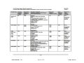
Errata A for MN-LPOD-R Rev 1
Comtech EF Data Documentation Update
Subject:
Errata Part Number:
PLM CO Number:
Comments:
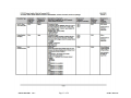
ER-LPODR-EA1
Update Section 2.3, added KT-0020987, LPOD-R PS.5 OMT Mounting Kit
ER-LPODR-EA1 (Errata documents are not revised)
C-0032769
See attached page(s). The new information will be included in the next released revision
of the manual.
Rev -
PLM C-0032769
ER-LPODR-EA1
Rev -
PLM C-0032769
ER-LPODR-EA1
Rev -
PLM C-0032769
ER-LPODR-EA1
Rev -
PLM C-0032769
ER-LPODR-EA1
Rev -
PLM C-0032769
ER-LPODR-EA1
Rev -
PLM C-0032769
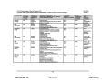
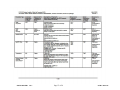
Errata B for MN-LPOD-R Rev 1
Comtech EF Data Documentation Update
Subject:
Errata Part Number:
PLM CO Number:
Comments:
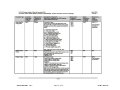
ER-LPODR-EB1
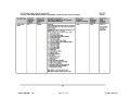
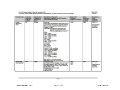
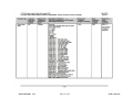
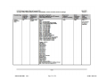
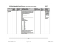
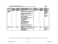
Add Appendix C. OPTIONAL SERIAL-BASED REMOTE PRODUCT MANAGEMENT, Customer Commands, all but PS.5
packages
ER-LPODR-EB1 (Errata documents are not revised)
C-0033316
See attached page(s). The new information will be included in the next released revision of the manual.
Rev -
Page 1 of 28
PLM C-0033316
ER-LPODR-EB1
Rev -
Page 2 of 28
PLM C-0033316
ER-LPODR-EB1
Rev -
Page 3 of 28
PLM C-0033316
ER-LPODR-EB1
Rev -
Page 4 of 28
PLM C-0033316
ER-LPODR-EB1
Rev -
Page 5 of 28
PLM C-0033316
ER-LPODR-EB1
Rev -
Page 6 of 28
PLM C-0033316
ER-LPODR-EB1
Rev -
Page 7 of 28
PLM C-0033316
ER-LPODR-EB1
Rev -
Page 8 of 28
PLM C-0033316
ER-LPODR-EB1
Rev -
Page 9 of 28
PLM C-0033316
ER-LPODR-EB1
Rev -
Page 10 of 28
PLM C-0033316
ER-LPODR-EB1
Rev -
Page 11 of 28
PLM C-0033316
ER-LPODR-EB1
Rev -
Page 12 of 28
PLM C-0033316
ER-LPODR-EB1
Rev -
Page 13 of 28
PLM C-0033316
ER-LPODR-EB1
Rev -
Page 14 of 28
PLM C-0033316
ER-LPODR-EB1
Rev -
Page 15 of 28
PLM C-0033316
ER-LPODR-EB1
Rev -
Page 16 of 28
PLM C-0033316
ER-LPODR-EB1
Rev -
Page 17 of 28
PLM C-0033316
ER-LPODR-EB1
Rev -
Page 18 of 28
PLM C-0033316
ER-LPODR-EB1
Rev -
Page 19 of 28
PLM C-0033316
ER-LPODR-EB1
Rev -
Page 20 of 28
PLM C-0033316
ER-LPODR-EB1
Rev -
Page 21 of 28
PLM C-0033316
ER-LPODR-EB1
Rev -
Page 22 of 28
PLM C-0033316
ER-LPODR-EB1
Rev -
Page 23 of 28
PLM C-0033316
ER-LPODR-EB1
Rev -
Page 24 of 28
PLM C-0033316
ER-LPODR-EB1
Rev -
Page 25 of 28
PLM C-0033316
ER-LPODR-EB1
Rev -
Page 26 of 28
PLM C-0033316
ER-LPODR-EB1
Rev -
Page 27 of 28
PLM C-0033316
ER-LPODR-EB1
Rev -
Page 28 of 28
PLM C-0033316
TABLE OF CONTENTS
About this Manual .............................................................................................................................. ix
Related Documents .................................................................................................................................. ix
Disclaimer................................................................................................................................................. ix
Conventions and References ................................................................................................................ x
Patents and Trademarks ........................................................................................................................... x
Warnings, Cautions, and Notes................................................................................................................. x
Examples of Multi-Hazard Notices ............................................................................................................ x
Recommended Standard Designations ..................................................................................................... x
Electrical Safety Notice ....................................................................................................................... xi
Installation Guidelines Regarding Power Line Quality ......................................................................... xi
Product Support................................................................................................................................. xii
Comtech EF Data Headquarters.......................................................................................................... xii
Warranty Policy .................................................................................................................................xiii
Limitations of Warranty ..........................................................................................................................xiii
13BExclusive Remedies .................................................................................................................................xiii
CHAPTER 1.
INTRODUCTION ............................................................................................. 1–1
1.1
Overview .............................................................................................................................. 1–1
1.2
Functional Description .......................................................................................................... 1–1
1.3
Features ............................................................................................................................... 1–2
1.3.1 The Solid-State Advantage........................................................................................................ 1–2
1.3.2 “Smart BUC” Functionality ....................................................................................................... 1–2
1.3.3 Enhanced Standard Features .................................................................................................... 1–2
1.3.3.1 Advanced FSK .................................................................................................................... 1–2
1.3.3.2 Data Logging Capability ..................................................................................................... 1–2
1.3.3.3 Hand-Held Controller Devices ........................................................................................... 1–2
1.4
Theory of Operation ............................................................................................................. 1–3
1.4.1 SSPA Block Diagrams ................................................................................................................ 1–3
1.4.2 SSPA Module............................................................................................................................. 1–3
1.4.3 Cooling System ......................................................................................................................... 1–4
1.4.4 Monitor and Control (M&C) ..................................................................................................... 1–4
1.4.5 Power Supply ............................................................................................................................ 1–4
1.4.6 Block Up Converter (BUC) Input ............................................................................................... 1–5
iii
LPOD-R Outdoor Amplifier / Block Up Converter (BUC)
Table of Contents
MN-LPODR
Revision 1
1.5
Summary of Specifications .................................................................................................... 1–6
1.5.1 Characteristics .......................................................................................................................... 1–6
1.5.2 Environmental .......................................................................................................................... 1–8
1.5.3 Physical ..................................................................................................................................... 1–8
1.6
Dimensional Envelopes ......................................................................................................... 1–8
1.6.1 LPOD-R PS .5 Dimensional Envelopes ....................................................................................... 1–9
1.6.2 LPOD-R PS 1 Dimensional Envelopes ...................................................................................... 1–10
1.6.3 LPOD-R PS 1.5 Dimensional Envelopes ................................................................................... 1–12
CHAPTER 2.
2.1
SYSTEM CONNECTIONS, INSTALLATION AND STARTUP ....................... 2–1
Overview .............................................................................................................................. 2–1
2.2
Interface Connectors ............................................................................................................ 2–3
2.2.1 Connector J1 | LBAND IN .......................................................................................................... 2–3
2.2.2 Connector J2 | RF OUT ............................................................................................................. 2–3
2.2.3 Connector J3 | POWER IN AC Power Mains ............................................................................. 2–3
2.2.3.1 LPOD-R PS 1, PS 1.5 J3 | POWER IN AC Power Main ........................................................ 2–4
2.2.4 Connector J3 | POWER IN Optional DC Power Mains .............................................................. 2–4
2.2.4.1 LPOD-R PS .5 J3 | POWER IN DC Power Main Option ....................................................... 2–4
2.2.4.2 LPOD-R PS 1 J3 | POWER IN DC Power Main Option ........................................................ 2–5
2.2.4.3 LPOD-R PS 1.5 J3 | POWER IN DC Power Main Option ..................................................... 2–5
2.2.5 Connector J6 | COM1 (Remote Communications and Discrete Control Port – PS 1, PS 1.5 ONLY)
2–6
2.2.6 Connector J6 | COM1 (Ethernet Communications Port – PS .5 ONLY).................................... 2–7
2.2.6.1 Fabricating a Weatherproof Ethernet Cable ..................................................................... 2–7
2.2.7 Ground Connector .................................................................................................................... 2–9
2.3
Single Thread (Standalone) LPOD-R Installation .................................................................. 2–10
2.4
Set the LPOD-R Power On ................................................................................................... 2–12
2.4.1 Monitoring LPOD-R Operation with the LED Indicator (PS .5 ONLY) ...................................... 2–12
CHAPTER 3.
UPDATING FIRMWARE ................................................................................. 3–1
3.1
Introduction ......................................................................................................................... 3–1
3.1.1 LPOD-R Firmware Update Process Summary ........................................................................... 3–1
3.2
Prepare for the Firmware Download..................................................................................... 3–1
3.2.1 Required User-supplied Items .................................................................................................. 3–1
3.2.1.1 LPOD-R PS .5 connections ................................................................................................ 3–2
3.2.1.2 LPOD-R PS 1 or PS 1.5 connections ................................................................................... 3–2
3.2.2 Configure the Terminal Emulator Program, if necessary ......................................................... 3–3
3.2.3 Find the LPOD-R firmware and version numbers ..................................................................... 3–3
3.2.3.1 Use the Web Server Interface to find the firmware version ............................................ 3–3
3.2.3.2 Use the optional serial remote control to find the firmware version .............................. 3–4
iv
LPOD-R Outdoor Amplifier / Block Up Converter (BUC)
Table of Contents
3.2.4
3.2.5
3.2.6
3.2.7
3.2.8
MN-LPODR
Revision 1
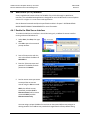
Make a temporary folder (subdirectory) on the User PC ......................................................... 3–4
Use the Windows Desktop to make a temporary folder .......................................................... 3–5
Use Windows Explorer to make a temporary folder ................................................................ 3–5
Use the Run and Browse windows to make a temporary folder.............................................. 3–5
Use Windows Command line to make a temporary folder ...................................................... 3–6
3.3
Download and Extract the Firmware Update Files................................................................. 3–7
3.3.1 About Firmware Numbers, File Versions, and Formats............................................................ 3–7
3.3.2 Steps to Download and Extract the Firmware Update Files ..................................................... 3–7
3.3.2.1 Use the Windows Desktop to see the folder contents ..................................................... 3–8
3.3.2.2 Use the Windows Command line to see the folder contents ........................................... 3–9
3.4
FTP Upload the Firmware Files and Update the LPOD-R Unit ................................................ 3–9
3.4.1 Important Considerations......................................................................................................... 3–9
3.4.2 Steps to FTP Upload the Firmware Files ................................................................................... 3–9
3.4.3 Steps to Update the LPOD-R Unit ........................................................................................... 3–10
3.5
Recover the User Interface Access....................................................................................... 3–11
3.5.1 Recovery Steps Using a Windows PC. ..................................................................................... 3–11
CHAPTER 4.
ETHERNET-BASED REMOTE PRODUCT MANAGEMENT ......................... 4–1
4.1
Introduction ......................................................................................................................... 4–1
4.1.1 Prerequisites ............................................................................................................................. 4–1
4.2
SNMP Interface .................................................................................................................... 4–2
4.2.1 Management Information Base (MIB) Files.............................................................................. 4–2
4.2.1.1 ComtechEFData Root MIB file ........................................................................................... 4–2
4.2.1.2 LPOD-R MIB file ................................................................................................................. 4–3
4.2.1.3 LPOD-R Traps MIB file ...................................................................................................... 4–3
4.2.2 SNMP Community Strings ......................................................................................................... 4–3
4.3
Telnet Interface .................................................................................................................... 4–4
4.3.1 Using the Telnet Interface for Remote Control Operation....................................................... 4–4
4.3.2 Using HyperTerminal for Telnet Remote Control Operation ................................................... 4–4
4.4
Web Server (HTTP) Interface ................................................................................................. 4–7
4.4.1 Enable the Web Server Interface.............................................................................................. 4–7
4.4.2 User Login ................................................................................................................................. 4–8
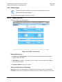
4.4.3 Web Server Interface Operation .............................................................................................. 4–9
4.4.3.1 Menu Tree ......................................................................................................................... 4–9
4.4.3.2 Page Navigation ................................................................................................................ 4–9
4.4.3.3 Page Sections .................................................................................................................... 4–9
4.4.3.4 Action Buttons .................................................................................................................. 4–9
4.4.3.5 Drop-down Lists .............................................................................................................. 4–10
4.4.3.6 Text or Data Entry ........................................................................................................... 4–10
4.4.4 Home Pages ............................................................................................................................ 4–10
v
LPOD-R Outdoor Amplifier / Block Up Converter (BUC)
Table of Contents
MN-LPODR
Revision 1
4.4.4.1 Home | Home ................................................................................................................. 4–10
4.4.4.2 Home | Contact / Home | Support pages....................................................................... 4–10
4.4.5 Admin Pages ........................................................................................................................... 4–11
4.4.5.1 Admin | Access................................................................................................................ 4–11
4.4.5.2 Admin | SNMP ................................................................................................................ 4–13
4.4.6 Config Pages............................................................................................................................ 4–14
4.4.6.1 Config | Amplifier ............................................................................................................ 4–14
4.4.6.2 Config | Utility ................................................................................................................. 4–15
4.4.7 Status Pages ............................................................................................................................ 4–17
4.4.7.1 Status | Summary ........................................................................................................... 4–17
4.4.7.2 Status | Status ................................................................................................................. 4–18
4.4.7.3 Status | MOP ................................................................................................................... 4–19
4.4.7.4 Status | Events ................................................................................................................ 4–20
4.4.7.5 Status | Statistics ............................................................................................................ 4–21
4.4.7.6 Status | Trending Graphs ................................................................................................ 4–22
CHAPTER 5.
5.1
OPTIONAL SERIAL-BASED REMOTE PRODUCT MANAGEMENT ............ 5–1
Overview .............................................................................................................................. 5–1
5.2
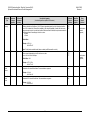
Key Operational Parameters / Common Commands and Queries) ........................................ 5–1
5.2.1 End-of-Life Commands ............................................................................................................. 5–3
5.3
Remote Control Protocol and Structure ................................................................................ 5–3
5.3.1 EIA-485...................................................................................................................................... 5–3
5.3.2 EIA-232...................................................................................................................................... 5–4
5.3.3 Basic Protocol ........................................................................................................................... 5–4
5.3.4 Packet Structure ....................................................................................................................... 5–5
5.3.4.1 Start of Packet ................................................................................................................... 5–5
5.3.4.2 Target Address .................................................................................................................. 5–6
5.3.4.3 Address Delimiter.............................................................................................................. 5–6
5.3.4.4 Instruction Code ................................................................................................................ 5–6
5.3.4.5 Instruction Code Qualifier ................................................................................................. 5–6
5.3.4.6 Optional Message Arguments........................................................................................... 5–7
5.3.4.7 End of Packet .................................................................................................................... 5–7
5.4
Remote Commands and Queries ........................................................................................... 5–8
APPENDIX A.
A.1
CABLE DRAWINGS ...................................................................................... A-1
Overview ...............................................................................................................................A-1
A.2
Control and Data Cables ........................................................................................................ A-1
A.2.1 Serial Interface Cable ................................................................................................................ A-2
A.2.2 Ethernet Interface Cable........................................................................................................... A-3
A.2.3 Ethernet Data Cable (CAT5 RJ-45) ............................................................................................ A-4
vi
LPOD-R Outdoor Amplifier / Block Up Converter (BUC)
Table of Contents
MN-LPODR
Revision 1
A.3
RF Cables ...............................................................................................................................A-5
A.3.1 RF Cable (Type N)...................................................................................................................... A-6
APPENDIX B.
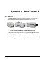
MAINTENANCE ............................................................................................ B–1
B.1
Introduction ......................................................................................................................... B–1
B.2
Cleaning the LPOD-R PS .5 Heat Sinks ................................................................................... B–2
B.3
Cleaning the LPOD-R PS 1 Heat Sinks (FUTURE) ..................................................................... B–6
B.4
Cleaning the LPOD-R PS 1.5 Heat Sinks (FUTURE) .................................................................. B–9
TABLES
Table 2-1. J2 | RF OUT Interface Type ..................................................................................................... 2–3
Table 2-2. LPOD-R PS 1/PS 1.5 J3 | POWER IN Pin Assignments......................................................... 2–4
Table 2-3. LPOD-R PS 1 J3 | POWER IN Pin Assignments .................................................................... 2–5
Table 2-4. LPOD-R PS 1 J3 | POWER IN Pin Assignments .................................................................... 2–5
Table 2-5. LPOD-R PS 1.5 J3 | POWER IN Pin Assignments ................................................................. 2–5
Table 2-6. LPOD-R J6 | COM1 Pin Assignments ..................................................................................... 2–6
FIGURES
Figure 1-1. Comtech EF Data LPOD-R Outdoor Amplifiers / BUCs ......................................................... 1–1
Figure 1-2. LPOD-R Typical Block Diagram ............................................................................................. 1–3
Figure 1-3. LPOD-R PS .5 LED Indicator ................................................................................................. 1–4
Figure 1-4. LPOD-R PS .5 Ku-Band Unit – DC Power, Waveguide Output ............................................. 1–9
Figure 1-5. LPOD-R PS 1 C-Band Unit – AC Power, Coaxial Output (FUTURE) .................................. 1–10
Figure 1-6. LPOD-R PS 1 C-Band Unit – AC Power, Waveguide Output (FUTURE) ............................ 1–11
Figure 1-7. LPOD-R PS 1.5 Ku-Band Unit – AC or DC Power, Waveguide Output (FUTURE) ............. 1–12
Figure 2-1. LPOD-R PS .5 Connectors ..................................................................................................... 2–2
Figure 2-2. LPOD-R PS 1 Connectors ...................................................................................................... 2–2
Figure 2-3. LPOD-R PS 1.5 Connectors ................................................................................................... 2–2
Figure 2-4. LPOD-R Ethernet Connector Field Termination Kit Assembly ............................................... 2–8
Figure 2-5. LPOD-R Ground Connector Locations ................................................................................... 2–9
Figure 2-6. PL/12319-1 Universal Pole Mounting Kit .............................................................................. 2–10
Figure 2-7. KT-0000095 LPOD-R PS 1, 1.5 Single Thread Mounting Kit ............................................... 2–11
Figure 2-8. LPOD-R PS .5 LED Indicator ............................................................................................... 2–12
Figure 3-1. Monitor and Control Utilities Available from Comtech EF Data .............................................. 3–2
Figure 4-1. LPOD-R .5 Unit Home Page................................................................................................. 4–10
Figure 4-2. Admin | Access Page............................................................................................................ 4–11
Figure 4-3. Admin | SNMP Page ............................................................................................................. 4–13
Figure 4-4. Config | Amplifier Page ......................................................................................................... 4–14
Figure 4-5. Config | Utility Page ........................................................................................................... 4–15
Figure 4-6. Status | Summary Page ........................................................................................................ 4–17
Figure 4-7. Status | Status Page ............................................................................................................. 4–18
vii
LPOD-R Outdoor Amplifier / Block Up Converter (BUC)
Table of Contents
MN-LPODR
Revision 1
Figure 4-8. Status | MOP Page ............................................................................................................... 4–19
Figure 4-9. Status | Events Page ............................................................................................................ 4–20
Figure 4-9. Status | Statistics Page ......................................................................................................... 4–21
Figure 4-11. Status | Trending Graphs Example .................................................................................... 4–22
Figure 4-12. Status | Trending Graphs Example, continued ................................................................... 4–23
Figure A-1. Serial Interface Cable (CEFD P/N CA-0020526, part of KT-0020518) .................................. A-2
Figure A-2. Ethernet Interface Cable (CEFD P/N CA-0000352, part of KT-0000203) ............................. A-3
Figure A-3. Ethernet Data Cable (CEFD P/N PP/CAT5FF7FTGY) .......................................................... A-4
Figure A-4. 1/4" Heliax Coaxial Cable (CA/3722-X) ................................................................................. A-6
Figure B-1. Comtech EF Data LPOD-R Outdoor Amplifiers / BUCs.........................................................B–1
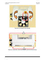
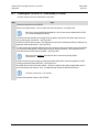
Figure B-2. LPOD-R PS .5 Cover Plate Screw Locations ........................................................................B–3
Figure B-3. Remove the Cover Plate ........................................................................................................B–3
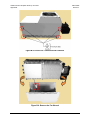
Figure B-4. Set Aside the Fan Assembly ..................................................................................................B–4
Figure B-5. LPOD-R PS .5 Heat Sink Locations (Fan Not Shown for Clarity) ..........................................B–4
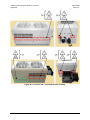
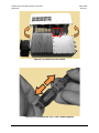
Figure B-6. Reseat the Fan Assembly ......................................................................................................B–5
Figure B-7. Replace the Cover Plate ........................................................................................................B–5
Figure B-8. LPOD-R PS 1 Shroud Screw Locations .................................................................................B–7
Figure B-9. Remove the Fan Shroud ........................................................................................................B–7
Figure B-10. Disconnect the Fan Power Supply .......................................................................................B–8
Figure B-11. LPOD-R PS 1 Heat Sink Locations ......................................................................................B–8
Figure B-12. Reconnect the Fan Power Supply........................................................................................B–8
Figure B-13. LPOD-R PS 1.5 Shroud Screw Locations..........................................................................B–10
Figure B-14. Remove the Fan Shroud ....................................................................................................B–11
Figure B-15. Disconnect the Fan 1 / Fan 2 Power Supplies ...................................................................B–11
Figure B-16. LPOD-R PS 1.5 Heat Sink Location ..................................................................................B–12
Figure B-17. Reconnect the Fan 1 / Fan 2 Power Supplies ...................................................................B–12
viii
PREFACE
About this Manual
This manual is applicable to LPOD-R units as listed:
•
LPOD-R PS 1 and 1.5 units, all firmware versions.
•
LPOD-R PS.5 units, firmware FW-0020841 and later.
Earlier LPOD-R PS 0.5 units with FW-0020765 are documented in the LPOD-R manual,
revision 0.
This manual gives installation and operation information for the Comtech EF Data LPOD-R family
of Outdoor Amplifiers / Block Up Converter (BUCs). This document is meant for anyone who
installs or operates the LPOD-R.
Related Documents
•
Comtech EF Data CLC-10 Handheld Terminal M&C Accessory for LPOD or SPOD PS 1, PS 1.5, PS 2
User’s Guide (CEFD P/N MN-CLC10)
•
Comtech EF Data LPODnet M&C Netbook Accessory for LPOD or SPOD PS 1, PS 1.5, PS 2
Operation Manual (CEFD P/N MN-LPODNET)
Disclaimer
Comtech EF Data has reviewed this manual thoroughly in order to provide an easy-to-use guide to
this equipment. All statements, technical information, and recommendations in this manual and in
any guides or related documents are believed reliable, but the accuracy and completeness thereof
are not guaranteed or warranted, and they are not intended to be, nor should they be understood
to be, representations or warranties concerning the products described. Further, Comtech EF Data
reserves the right to make changes in the specifications of the products described in this manual at
any time without notice and without obligation to notify any person of such changes.
Contact Comtech EF Data Product Support if you have any questions regarding this
equipment or the information in this manual.
ix
LPOD-R Outdoor Amplifier / Block Up Converter (BUC)
Preface
MN-LPODR
Revision 1
Conventions and References
Patents and Trademarks
See all of Comtech EF Data's Patents and Patents Pending at http://patents.comtechefdata.com.
Comtech EF Data acknowledges that all trademarks are the property of the trademark owners.
Warnings, Cautions, and Notes
A WARNING informs you about a possible hazard that MAY CAUSE DEATH or
SERIOUS INJURY.
A CAUTION informs you about a possible hazard that MAY CAUSE INJURY or
PROPERTY DAMAGE.
A NOTE gives you important information about a task or the equipment.
A REFERENCE directs you to additional information about a task or the equipment.
Examples of Multi-Hazard Notices
Recommended Standard Designations
The new designation of the Electronic Industries Association (EIA) supersedes the Recommended
Standard (RS) designations. References to the old designations may be shown when depicting
actual text (e.g., RS-232) displayed on the physical product, LPOD-R Web Server pages or optional
serial remote interface. All other references in the manual refer to EIA designations.
x
LPOD-R Outdoor Amplifier / Block Up Converter (BUC)
Preface
MN-LPODR
Revision 1
Electrical Safety Notice
CAUTION – Neutral Fusing – Double pole/neutral fusing is used on the prime power
supply input.
This equipment has been designed to minimize exposure of personnel to hazards. For further
information, contact Comtech EF Data, Customer Support Department. The operators and
technicians must:
•
•
•
•
Know how to work around, with, and on high voltage equipment.
Exercise every precaution to ensure personnel safety.
Exercise extreme care when working near high voltages.
Be familiar with the warnings presented in this manual.
Installation Guidelines Regarding Power Line Quality
Comtech EF Data has become familiar with the varying quality of the AC power grid
around the world. Observing the following installation guidelines should help ensure a
reliable installation.
•
Surge suppression: High voltage surges can cause failure of the power supply. These surges
are typically caused by circuit switching on the main AC power grid, erratic generator
operation, and also by lightning strikes. While the LPOD-R does have built in surge
suppression, if the unit is to be installed in a location with questionable power grid quality,
Comtech EF Data recommends installation of additional power conditioning/surge
suppression at the power junction box.
•
Grounding: The LPOD-R provides a grounding terminal. This is provided to allow you to
ground the LPOD-R to the antenna’s grounding network. All components installed at the
antenna should be grounded to a common grounding point at the antenna.
•
Electrical welding: If welding needs to take place at the antenna, disconnect all cables from
the LPOD-R except for the ground wire. Cap all RF connections with terminations. This will
prevent damage to the input/output circuitry of the LPOD-R.
•
Lightning: Lightning strikes on or around the antenna will generate extremely high voltages
on all cables connected to the LPOD-R. Depending on the severity of the strike, the LPOD-R’s
internal surge protection combined with the recommended external suppression may
protect the LPOD-R’s power supply. However, if the installation will be in an area with a high
probability of lightning strikes, Comtech EF Data recommends the installation of surge
suppression on the RF and IF cables. One source of these suppressors is PolyPhaser
(www.polyphaser.com).
2H
xi
LPOD-R Outdoor Amplifier / Block Up Converter (BUC)
Preface
MN-LPODR
Revision 1
Product Support
For all product support, please call:
+1.240.243.1880
+1.866.472.3963 (toll free USA)
Comtech EF Data Headquarters
http://www.comtechefdata.com
Comtech EF Data Corp.
2114 West 7th Street
Tempe, Arizona USA 85281
+1.480.333.2200
xii
LPOD-R Outdoor Amplifier / Block Up Converter (BUC)
Preface
MN-LPODR
Revision 1
Warranty Policy
Comtech EF Data products are warranted against defects in material and workmanship for a specific period from the date of shipment,
and this period varies by product. In most cases, the warranty period is two years. During the warranty period, Comtech EF Data will, at
its option, repair or replace products that prove to be defective. Repairs are warranted for the remainder of the original warranty or a 90
day extended warranty, whichever is longer. Contact Comtech EF Data for the warranty period specific to the product purchased.
For equipment under warranty, the owner is responsible for freight to Comtech EF Data and all related customs, taxes, tariffs, insurance,
etc. Comtech EF Data is responsible for the freight charges only for return of the equipment from the factory to the owner. Comtech EF
Data will return the equipment by the same method (i.e., Air, Express, Surface) as the equipment was sent to Comtech EF Data.
All equipment returned for warranty repair must have a valid RMA number issued prior to return and be marked clearly on the return
packaging. Comtech EF Data strongly recommends all equipment be returned in its original packaging.
Comtech EF Data Corporation’s obligations under this warranty are limited to repair or replacement of failed parts, and the return
shipment to the buyer of the repaired or replaced parts.
Limitations of Warranty
The warranty does not apply to any part of a product that has been installed, altered, repaired, or misused in any way that, in the
opinion of Comtech EF Data Corporation, would affect the reliability or detracts from the performance of any part of the product, or is
damaged as the result of use in a way or with equipment that had not been previously approved by Comtech EF Data Corporation.
The warranty does not apply to any product or parts thereof where the serial number or the serial number of any of its parts has been
altered, defaced, or removed.
The warranty does not cover damage or loss incurred in transportation of the product.
The warranty does not cover replacement or repair necessitated by loss or damage from any cause beyond the control of Comtech EF
Data Corporation, such as lightning or other natural and weather related events or wartime environments.
The warranty does not cover any labor involved in the removal and or reinstallation of warranted equipment or parts on site, or any
labor required to diagnose the necessity for repair or replacement.
The warranty excludes any responsibility by Comtech EF Data Corporation for incidental or consequential damages arising from the use of
the equipment or products, or for any inability to use them either separate from or in combination with any other equipment or products.
A fixed charge established for each product will be imposed for all equipment returned for warranty repair where Comtech EF Data
Corporation cannot identify the cause of the reported failure.
Exclusive Remedies
13B
Comtech EF Data Corporation’s warranty, as stated is in lieu of all other warranties, expressed, implied, or statutory,
including those of merchantability and fitness for a particular purpose. The buyer shall pass on to any purchaser, lessee, or other user of
Comtech EF Data Corporation’s products, the aforementioned warranty, and shall indemnify and hold harmless Comtech EF Data
Corporation from any claims or liability of such purchaser, lessee, or user based upon allegations that the buyer, its agents, or employees
have made additional warranties or representations as to product preference or use.
The remedies provided herein are the buyer’s sole and exclusive remedies. Comtech EF Data shall not be liable for any direct, indirect,
special, incidental, or consequential damages, whether based on contract, tort, or any other legal theory.
xiii
LPOD-R Outdoor Amplifier / Block Up Converter (BUC)
Preface
MN-LPODR
Revision 1
BLANK PAGE
xiv
LPOD-R Outdoor Amplifier / Block Up Converter (BUC)
Introduction
MN-LPODR
Revision 1
Chapter 1. INTRODUCTION
1.1
Overview
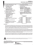
Comtech EF Data’s LPOD-R family of Outdoor Amplifiers / Block Up Converters (BUCs) – referred
to collectively throughout this manual as the LPOD-R – deliver rated power, guaranteed, to the
transmit waveguide flange at the 1 dB compression point. The LPOD-R is a cost-effective
alternative for the LPOD, where the full LPOD’s support of internal 10 M Hz and redundancy is
not required.
LPOD-R PS .5
LPOD-R PS 1
LPOD-R PS 1.5
Figure 1-1. Comtech EF Data LPOD-R Outdoor Amplifiers / BUCs
1.2
Functional Description
The LPOD-R serves as a more reliable replacement for Traveling Wave Tube (TWT) amplifiers in
satellite communications. The compact size and weight of the LPOD-R lends itself to any
installation with limited available mounting space. This includes ship-borne antenna systems,
small “flyaway” systems, and Satellite News Gathering (SNG) installations.
As shown in Figure 1-1, Comtech EF Data’s LPOD-R is available in three models: the PS .5, PS 1,
and PS 1.5. Each LPOD-R consists of a CEFD SSPA module with the Monitor/Control Processor
(MCP), a power supply, and a fan assembly. The amplifier features a Comtech EF Data low loss
combining technique and MCP-based temperature-versus-gain compensation.
1–1
LPOD-R Outdoor Amplifier / Block Up Converter (BUC)
Introduction
1.3
MN-LPODR
Revision 1
Features
1.3.1
The Solid-State Advantage
Comtech EF Data’s extensive experience in the design of outdoor RF transceivers led to the
LPOD-R family’s efficient thermal and mechanical package. The LPOD-R is constructed with
highly reliable gallium arsenide field-effect transistors (GaAs FETs). With third-order
intermodulation products that are 4 to 6 dB better than TWT ratings, the CEFD unit replaces
TWTs with saturated power levels of up to twice the LPOD-R’s rated output. The LPOD-R also
provides mean time between failures (MTBF) that is four to five times greater than the typical
TWT MTBF.
1.3.2
“Smart BUC” Functionality
The LPOD-R offers full 13.75 to 14.5 GHz Ku-Band and 5850 to 6725 MHz C-Band coverage while
supporting industry standard FSK modem/BUC communications, as well as Comtech EF Data
proprietary commands.
1.3.3
Enhanced Standard Features
The LPOD-R comes equipped with useful features that other manufacturers offer only as
options. Included in the base price are temperature compensation, power monitor, power
factor corrected supply, and full remote monitor and control (M&C) capabilities (including
Ethernet, FSK, and Comtech’s proprietary Advanced FSK).
1.3.3.1
Advanced FSK
The LPOD-R, when used with Comtech EF Data modems, provides enhanced functionality
utilizing the industry standard FSK communications channel. Advanced FSK offers full control of
single thread and, where applicable, redundant systems from the modem front panel, without
additional cabling or cost. Additionally, access the LPOD-R via the Ethernet M&C port of the
modem, and control it via Embedded Distant-end Monitor and Control (EDMAC).
1.3.3.2
Data Logging Capability
To enhance system maintainability, the LPOD-R includes a built-in data logging capability. By
recording critical operational parameters such as temperature, output power, mute status, etc.
at time stamped intervals, you can quickly gather intelligence about not only the unit itself but
also the unit’s operational environment.
1.3.3.3
Hand-Held Controller Devices
The LPOD-R accommodates a variety of hand-held controller devices. These include the
LPODnet M&C Accessory Kit and the CLC-10 M&C Accessory Kit. Both are designed to access the
monitor and control functionality of the LPOD-R.
1–2
LPOD-R Outdoor Amplifier / Block Up Converter (BUC)
Introduction
1.4
1.4.1
MN-LPODR
Revision 1
Theory of Operation
SSPA Block Diagrams
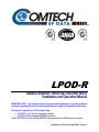
See Figure 1-2 for the LPOD-R block diagram. The major components of an LPOD-R unit are:
•
SSPA Module
•
Cooling System
•
Monitor and Control (M&C)
•
Power Factor Corrected Power Supply (PS 1 and PS 1.5 packages)
Figure 1-2. LPOD-R Typical Block Diagram
1.4.2
SSPA Module
The amplifier module performs the core function of the unit. An isolator is at the RF input to
ensure good voltage standing wave ratio (VSWR). The RF signal then passes through an
electronically controlled attenuator that adjusts the overall attenuation according to the user
input. After some amplification, a second attenuator is automatically controlled via a look-up
table to maintain the amplifier gain at a constant level over temperature variations.
The RF signal is then amplified by a multi-stage design that utilizes proprietary combining
techniques to meet the rated power requirements. The output circuitry contains a coupler to
provide a sampled signal for monitoring purposes. A power detector circuit also is included and
the reading can be accessed via remote communication. A high power circulator and load is
located at the output to provide good VSWR and protection from external mismatch.
1–3
LPOD-R Outdoor Amplifier / Block Up Converter (BUC)
Introduction
1.4.3
MN-LPODR
Revision 1
Cooling System
The PS .5 contains a single fan that is always enabled. The PS 1 contains one temperaturecontrolled fan, and the PS 1.5 contains two temperature-controlled fans.
1.4.4
Monitor and Control (M&C)
The LPOD-R includes a microprocessor-based system that provides monitoring and control of
the essential parameters of the unit. You interface with the unit through the M&C system via
the remote control/discrete communications port. The unit is capable of Ethernet remote
communication, while EIA-232/485 is optional on the PS 1 and PS 1.5 packages. A discrete mute
control and relay status output is also available on the PS 1 and PS 1.5 packages.
The M&C system monitors the fan speed, unit temperature, all power supply voltages, power
transistor currents, output power, etc. Should a critical monitored parameter fail, the unit will
mute the RF signal and report a fault. The details of the fault can be accessed via remote
communication.
The LPOD-R PS .5 features a Light-Emitting Diode (LED) Indicator. Figure 1-3 shows the location
of this feature, on the signal output side of the LPOD-R PS .5 housing, next to the ground lug.
This LED provides you with visual cues to the operational, online, and offline status of the
system. See Chapter 2 for complete details about interpreting LED operation.
Figure 1-3. LPOD-R PS .5 LED Indicator
1.4.5
Power Supply
The LPOD-R features a power supply that is power factor corrected. It supplies several voltages
necessary for the unit to operate:
The 10V power supply output state is controlled by circuitry within the RF module. If the RF
module does not have the –5.8V supply for any reason, it will not allow the 10V power supply to
turn on. This protects the power transistors within the RF module from failure due to improper
power supply sequencing.
The +24V output powers the cooling fans, is the source of power for waveguide switching when
the SSPA is used in redundant configurations, and is dropped to +22V for LNB bias.
The +5.8V, -5.8V, +7.8V and +13.5V outputs are used to operate the M&C board and other
overhead functions.
1–4
LPOD-R Outdoor Amplifier / Block Up Converter (BUC)
Introduction
1.4.6
MN-LPODR
Revision 1
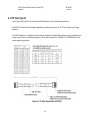
Block Up Converter (BUC) Input
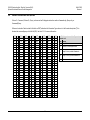
The LPOD-R translates an L-Band input carrier to the desired output frequency (C-, X-, or KuBand). LO frequencies are as follows:
BUC C, Ku, X LO Frequencies
Band
Frequency
LO Frequency
Inverting
5850 to 6650 MHz
4900 MHz
No
5950 to 6700 MHz
5000 MHz
No
Insat C-Band
6725 to 7025 MHz
5760 MHz
No
Ku-Band
14.00 to 14.50 GHz
13.050 GHz
No
Ku-Band-W
13.75 to 14.50 GHz
12.800 GHz
No
X-Band
7900 to 8400 MHz
6950 MHz
No
C-Band
1–5
LPOD-R Outdoor Amplifier / Block Up Converter (BUC)
Introduction
1.5
1.5.1
MN-LPODR
Revision 1
Summary of Specifications
Characteristics
IF Input Frequency Note 1
RF Output Frequency
950 – 1525 MHz
5.850 – 6.425 GHz
950 – 1750 MHz
5.850 – 6.650 GHz (optional)
950 – 1825 MHz
5.850 – 6.725 GHz (optional)
965 – 1265 MHz
6.725 – 7.025 GHz
950 – 1450 MHz
7.900 – 8.400 GHz
950 – 1450 MHz
14.00 – 14.50 GHz
950 – 1750 MHz
13.75 – 14.50 GHz (optional)
Psat (Typical)
P1dB (Guaranteed) Note 1
PS.5-10Ku
40 dBm (10 W)
39 dBm (8 W)
PS.5-15Ku
42 dBm (16 W)
40.75 dBm (12 W)
PS1-20Ku
43 dBm (20 W)
42 dBm (16 W)
PS1-32Ku
45 dBm (32 W)
44 dBm (25 W)
PS1-40Ku
46 dBm (40 W)
45 dBm (25 W)
PS1.5-50Ku
47 dBm (50 W)
46 dBm (40 W)
PS1.5-60Ku
48 dBm (60 W)
47 dBm (50 W)
PS.5-15C
41 dBm (15 W)
40 dBm (10 W)
PS1-25C,X
44 dBm (25 W)
43 dBm (20 W)
PS1-32C,X
45 dBm (32 W)
44 dBm (25 W)
PS1-40C,X
46 dBm (40 W)
45 dBm (32 W)
PS1-50C,X
47 dBm (50 W)
46 dBm (40 W)
PS1-60 C,X
48 dBm (60 W)
47 dBm (50 W)
PS1.5-75 C,X
48.6 dBm (75 W)
48 dBm (60 W)
PS1.5-80 C,X
49 dBm (80 W)
48.5 dBm (70 W)
PS1.5-100 C,X
50 dBm (100 W)
49 dBm (80 W)
PS1.5-110 C,X
50.4 dBm (110 W)
49.5 dBm (90 W)
PS1.5-125 C,X
51 dBm (125 W)
50 dBm (100 W)
Model
Ku-Band Units
C-Band and/or
X-Band Units
Notes:
1. Allow 1 dB degradation from 13.75 to 14.0 GHz and 6425 to 6725 MHz.
Gain Min (Typical)
PS .5
60 (65 dB)
PS 1, 1.5
70 (75dB)
Input Power Supply Requirements
90-264 VAC, 47-63 Hz, Power Factor Corrected, .96 (PS 1, 1.5
only)(48 VDC optional)
Max IF Input level (no damage)
+10 dBm
1–6
LPOD-R Outdoor Amplifier / Block Up Converter (BUC)
Introduction
Gain Adjust
MN-LPODR
Revision 1
PS .5
10 dB in 0.25 dB steps
PS 1, 1.5
20 dB in 0.25 dB steps
Gain Flatness
±1.5 dB full band (optional ±2.0 dB full band (-50° to +55°C))
±0.40 dB per 40 MHz (optional ±0.50 dB per 40 MHz (-50° to +55°C))
Gain variation over temp
±1.5 dB max, -40° to +55°C (optional ±2.0 dB max (-50° to +55°C))
Input Return Loss
14 dB (1.5:1 VSWR)
Output Return Loss
17.7 dB (1.3:1 VSWR)
Noise Figure
15 dB typical, 20 dB max @ min attenuation
RF Mute Isolation
-60 dBc min
AM/PM Conversion
2° typical, 3.5° max @ Rated P1dB output power
Third-order Intermodulation Level
(2 tones, @ -3 dB Total Backoff
from P1 dB (-6 dBc SCL), Δ
1MHz)
-30 dBc typ., -25 dBc Guaranteed
Harmonics -50 dBc @ Prated – 3 dB
Spurious Level
Group delay variation
Carrier
Related
In-band
-60 dBc min @ P1dB
NonCarrier
Related
In-band
-60 dBm max ( Input Terminated)
LO
Leakage
-25 dBm max
Linear
± 0.03 ns/MHz
Parabolic
±0 .003 ns/MHz2
Ripple
± 1.0 ns pk-pk
Data Logging Parameters
Non-Volatile RAM: Capacity 30 days @ 90-minute intervals.
Includes:
RF Output Power
Mute Status
Heatsink Temperature
Phase Noise (dBc/Hz) (with optional internal or
equivalent performance external reference)
Offset
Typical (C/X/Ku) dBc/Hz
Spec (C/X/Ku) dBc/Hz
100 Hz
-65
-62
1 KHz
-75
-72
10 KHz
-85
-82
100 KHz
-95
-92
1 MHz
-105
-102
1–7
LPOD-R Outdoor Amplifier / Block Up Converter (BUC)
Introduction
1.5.2
MN-LPODR
Revision 1
Environmental
Standard -40º to 122ºF (-40º to 55ºC)
Temperature
Operating
Optional
Storage
-58º to 131ºF (-50º to 55ºC) or -40º to 140ºF (-40º to
60ºC)
-67º to 167ºF (-55º to 75ºC)
Humidity
100% condensing rain 2” per hour
Altitude
10,000 AMSL
Shock
Normal commercial shipping and handling
1.5.3
Physical
PS .5
Weight
5 lbs. (2.3 kg) Nominal
PS 1
17 lbs. (9.1 kg) Nominal
PS1.5
Dimensions
(excluding connectors)
See Section 1.6.
PS .5
7.21 x 4.65 x 3.34 in. (183.1 x 118.1 x 84.8 mm)
PS 1
12.60 x 6.31 x 6.05 in. (320.0 x 160.3 x 153.7 mm)
PS 1.5
12.78 x 6.14 x 6.47 in. (324.6 x 155.9 x 164.3 mm)
IF/RF Input
Type ‘N’ Female
RF Output
PS .5
C-Band: CPR137G
Ku-Band: WR75G
PS 1
C-Band: Type ‘N’ Female (optional CPR137G)
X-Band: CPR112G
Ku-Band: WR75G
PS 1.5
C-Band: CPR137G
X-Band: CPR112G
Ku-Band: WR75G
Connectors
PS .5
M&C
PS 1
(Ethernet)
PS 1.5
1.6
Weatherized RJ-45
Optional 19-pin MS style (single integrated cable
assembly available, dependent upon configuration)
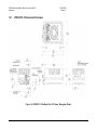
Dimensional Envelopes
Typical for all figures in each subsection, all dimensions are in inches. Bracketed dimensions,
where shown, are in metric units (mm).
1–8
LPOD-R Outdoor Amplifier / Block Up Converter (BUC)
Introduction
1.6.1
MN-LPODR
Revision 1
LPOD-R PS .5 Dimensional Envelopes
Figure 1-4. LPOD-R PS .5 Ku-Band Unit – DC Power, Waveguide Output
1–9
LPOD-R Outdoor Amplifier / Block Up Converter (BUC)
Introduction
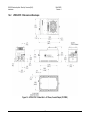
1.6.2
MN-LPODR
Revision 1
LPOD-R PS 1 Dimensional Envelopes
Figure 1-5. LPOD-R PS 1 C-Band Unit – AC Power, Coaxial Output (FUTURE)
1–10
LPOD-R Outdoor Amplifier / Block Up Converter (BUC)
Introduction
MN-LPODR
Revision 1
Figure 1-6. LPOD-R PS 1 C-Band Unit – AC Power, Waveguide Output (FUTURE)
1–11
LPOD-R Outdoor Amplifier / Block Up Converter (BUC)
Introduction
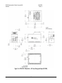
1.6.3
MN-LPODR
Revision 1
LPOD-R PS 1.5 Dimensional Envelopes
Figure 1-7. LPOD-R PS 1.5 Ku-Band Unit – AC or DC Power, Waveguide Output (FUTURE)
1–12
Chapter 2. SYSTEM
CONNECTIONS, INSTALLATION
AND STARTUP
2.1
Overview
This chapter summarizes the connectors provided for all necessary external connections
between the LPOD-R PS .5 (Figure 2-1), PS 1 (Figure 2-2), or PS 1.5 (Figure 2-3) models and other
equipment.
Basic installation and operational startup information is provided in Sect. 2.3. For a detailed
overview on the LPOD-Rs operability, see Chapter 4. ETHERNET-BASED REMOTE PRODUCT
MANAGEMENT or Chapter 5. OPTIONAL SERIAL-BASED REMOTE PRODUCT MANAGEMENT (for
EIA-232/485 remote M&C commands and/or queries).
2–1
LPOD-R Outdoor Amplifier / Block Up Converter
System Connections, Installation and Startup
MN-LPODR
Revision 1
Figure 2-1. LPOD-R PS .5 Connectors
Figure 2-2. LPOD-R PS 1 Connectors
Figure 2-3. LPOD-R PS 1.5 Connectors
2–2
LPOD-R Outdoor Amplifier / Block Up Converter
System Connections, Installation and Startup
2.2
MN-LPODR
Revision 1
Interface Connectors
2.2.1 Connector J1 | LBAND IN
The J1 | LBAND IN RF input connector is a Type N female connector. Typical input levels (30 dBm) depend on desired output power and unit attenuation. To prevent damage to the
LPOD-R, RF input levels must not exceed +15 dBm.
2.2.2 Connector J2 | RF OUT
WARNING
For safety reasons, never look directly into the waveguide output.
The J2 | RF OUT connector may be a waveguide or coaxial interface – the type of interface used
depends on the LPOD-R model and/or frequency range of the unit, as described in Table 2-1 and
as shown in Figures 2-1, 2-2, and 2-3.
Table 2-1. J2 | RF OUT Interface Type
Unit
Frequency / Output Type
Figure
PS .5
C-Band: CPR137G
Ku-Band: WR75G
PS 1
C-Band: Type N Female (optional CPR137G)
X-Band: CPR112G
Figure 2-2
Ku-Band: WR75G
Figure 2-1
C-Band: CPR137G
PS 1.5 X-Band: CPR112G
Ku-Band: WR75G
Figure 2-3
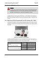
2.2.3 Connector J3 | POWER IN AC Power Mains
WARNING
For safety reasons, make sure you know that the J3 AC Power Connection pin
assignments for each LPOD-R model are different. You must use the correct
pin assignments.
Use of incorrect pin assignments can result in product damage or personal
injury.
For any AC-powered LPOD-R product, the prime power input requirement is as follows:
•
90-264 VAC
2–3
LPOD-R Outdoor Amplifier / Block Up Converter
System Connections, Installation and Startup
•
MN-LPODR
Revision 1
47 to 63 Hz
The power supply is power factor corrected. The total power required from the prime power
supply depends on the model used. Please refer to Sect. 1.5 Summary of Specifications.
2.2.3.1
LPOD-R PS 1, PS 1.5 J3 | POWER IN AC Power Main
The mating connector specification and pin assignments (Table 2-2) unique to the LPODR PS 1 and PS 1.5 AC power interfaces are as follows:
Mating Connector: CEFD P/N CN/MS-STPG03F02 (ITT Cannon KPT06B-12-35)
Table 2-2. LPOD-R PS 1/PS 1.5 J3 | POWER IN Pin Assignments
Pin
Description
A
LINE (L1)
B
NEUTRAL (L2)
C
GND
2.2.4 Connector J3 | POWER IN Optional DC Power Mains
WARNING
For safety reasons, make sure you know that the J3 AC Power Connection pin
assignments for each LPOD-R model are different. You must use the correct
pin assignments.
Use of incorrect pin assignments can result in product damage or personal
injury.
For all LPOD-R models, the prime power input requirement is 36-72 VDC. The total power
required from the prime power supply depends on the model used. See Sect. 1.5 Summary of
Specifications for more information.
2.2.4.1
LPOD-R PS .5 J3 | POWER IN DC Power Main Option
The mating connector specification and pin assignments (Table 2-3) unique to the
LPOD-R PS .5 optional DC power interface are as follows:
Mating Connector: CEFD P/N CN-0020708 (SOURIAU UTS6JC8E33S)
2–4
LPOD-R Outdoor Amplifier / Block Up Converter
System Connections, Installation and Startup
MN-LPODR
Revision 1
Table 2-3. LPOD-R PS 1 J3 | POWER IN Pin Assignments
Pin
2.2.4.2
LPOD-R PS .5 Assignment
A
V+
B
V-
C
GND (chassis ground)
LPOD-R PS 1 J3 | POWER IN DC Power Main Option
The mating connector specification and the pin assignments (Table 2-4) unique to the
LPOD-R PS 1 DC power interface are as follows:
Mating Connector: CEFD P/N CN/STPG04F01 (Glenair IPT06E-12-4-SSR-F7)
Table 2-4. LPOD-R PS 1 J3 | POWER IN Pin Assignments
Pin
2.2.4.3
LPOD-R PS 1 Assignment
A
V+
B
GND
C
V-
D
NO CONNECT
LPOD-R PS 1.5 J3 | POWER IN DC Power Main Option
The mating connector specification and the pin assignments (Table 2-5) unique to the
LPOD-R PS 1.5 DC power interface are as follows:
Mating Connector: CEFD P/N CN-0020517 (MS3116E-14-5S(476), Amphenol PT06E14-5S(476))
Table 2-5. LPOD-R PS 1.5 J3 | POWER IN Pin Assignments
Pin
LPOD-R PS 1.5 Assignment
A
+48V
B
+48V
C
-48V
D
-48V
E
GND
2–5
LPOD-R Outdoor Amplifier / Block Up Converter
System Connections, Installation and Startup
MN-LPODR
Revision 1
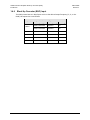
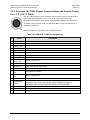
2.2.5 Connector J6 | COM1 (Remote Communications and Discrete Control
Port – PS 1, PS 1.5 ONLY)
The J6 | COM 1 discrete control connector is the primary input for controlling and
monitoring the LPOD-R PS1 and 1.5. It is a 19-pin circular connector, type
MS3112E14-19S, used for both standard Ethernet M&C (with use of a 19-pin to RJ45 adapter cable) or optional EIA-232/485 Serial M&C. The pinout specification is
contained in Table 2-6
Mating connector: ITT: KPT06J14-19P or MS3116J14-19P
Table 2-6. LPOD-R J6 | COM1 Pin Assignments
Pin
Name
A
RS485_+RX
B
RS485_-RX
C
RS485_+TX
D
RS485_-TX
Description
E
RS232_RD
Pin 3 of DB9 female connector
F
Ethernet TX+
Pin 3 of RJ45 female connector
G
RS232_TD
Pin 2 of DB9 female connector
H
Pin 6 of RJ45 female connector
K
Ethernet TXTX/RX Switch
Drive 1 Pos
Gnd
L
SUMFLT In
Open when faulted, else +5VDC
M
SUMFLT Out
TX Switch Pos 1
Ind
RX Switch Pos 1
Ind
+24V
When faulted, tied to Pin K, else open
T
Not for customer use
When AUX=1, unit is muted until this pin is tied to ground (Pin K). When tied to
System Mute
ground, the unit unmutes. See the AUX remote command in Chapter 5.
Control
OPTIONAL SERIAL-BASED REMOTE PRODUCT MANAGEMENT.
Switch Common GND reference for Pin N
U
Ethernet RX-
Pin 2 of RJ45 female connector
V
Ethernet RX+
Pin 1 of RJ45 female connector
J
N
P
R
S
Not for customer use
Ground (also Pin 5 of DB-9F connector)
Online/Offline indication
Not for customer use
2–6
LPOD-R Outdoor Amplifier / Block Up Converter
System Connections, Installation and Startup
MN-LPODR
Revision 1
2.2.6 Connector J6 | COM1 (Ethernet Communications Port – PS .5 ONLY)
Connector Type
Weatherproof RJ-45 female modular jack
(Samtec USA Corp. P/N RPBE-01)
Ref Des |
Name
J6 | COM 1
Direction
In/Out
CAUTION
For permanent Ethernet connections, you MUST use the appropriate mating connector
on your supplied Ethernet cable to ensure a weatherproof installation.
Comtech EF Data offers two mating connector kits (CEFD P/N KT-0020707 for 5.00-5.75 mm
jacket OD Ethernet cables, or CEFD P/N KT-0020708 for 5.75-6.50 mm jacket OD Ethernet
cables). See Sect. 2.2.6.1 and Figure 2-4.
This interface operates at 10/100/1000 Mbps, half and full duplex, auto-negotiating.
The maximum Ethernet packet size is 1522 bytes (including Ethernet headers and CRC).
2.2.6.1
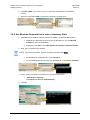
Fabricating a Weatherproof Ethernet Cable
Follow these steps to assemble the cable (see Figure 2-4):
Step
Task
1
Thread the user-supplied RJ-45 CAT5e Ethernet cable (Item 1) through the Item 2 components
(Items 2.3 through 2.6):
Be sure to strip the cable end 15mm.
Be sure to note the order and orientation of all kit items before final assembly of the components.
2
Crimp the RJ-45 modular plug (Item 2.1) onto Item 1. Be sure to maintain the cable wiring per the
Note 3 wiring table.
3
Snap Item 2.1 into the Ethernet Shroud (Item 2.2). Then, snap Item 2.2 into the Latched Housing
(Item 2.3).
4
Slide the Sealing Gland (Item 2.4) into its seated position in Item 2.3.
5
Slide the Compression Cage (Item 2.5) onto Item 2.4.
6
Screw the Cable Nut (Item 2.6) into assembled position against Item 2.3. (Be sure the mating
surfaces of the Latched Housing and Cable Nut are touching.) DO NOT OVERTIGHTEN.
2–7
LPOD-R Outdoor Amplifier / Block Up Converter
System Connections, Installation and Startup
MN-LPODR
Revision 1
Figure 2-4 Notes (Assembly Detail Source: Samtec USA Corporation)
1
2
3
Cable end is shown here as assembled.
Be sure to strip Item 1 to 15mm.
Be sure to maintain Item 1 to Item 2.5 wiring as follows:
POS COLOR
WIRE
01
WHITE/ORANGE
TWISTING
02
ORANGE
03
WHITE/GREEN
TWISTING
04
BLUE
05
WHITE/BLUE
TWISTING
Connector End View
06
GREEN
07
WHITE/BROWN
TWISTING
08
BROWN
Figure 2-4. LPOD-R Ethernet Connector Field Termination Kit Assembly
Item
1
Part No.
(Comtech/CEFD or
Samtec/SC)
Description
PROVIDED BY USER
5.6 mm OD or 6.5 mm OD 8-wire CAT5e Ethernet Cable, length A/R
KT-0020707 (CEFD)
Samtec USA P/N RCEF-G-01 RJ-45 Weatherproof Connector for
5.0-5.75 mm OD CAT5e Ethernet Cable
KT-0020708 (CEFD)
Samtec USA P/N RCEF-G-02 RJ-45 Weatherproof Connector for
5.75-6.5 mm OD CAT5e Ethernet Cable
2
2–8
LPOD-R Outdoor Amplifier / Block Up Converter
System Connections, Installation and Startup
Item
MN-LPODR
Revision 1
Part No.
(Comtech/CEFD or
Samtec/SC)
Description
2.1
SUB-MODP-01-8P8C-S01 (SC)
RJ-45 Modular Ethernet Plug
2.2
RCEF-B-02 (SC)
Ethernet Shroud, Nylon
2.3
RCEF-B-01 (SC)
Latched Housing, Nylon
SG-17-01 (SC)
Sealing Gland, Neoprene
(for 5.0-5.75 mm OD CAT5e Ethernet Cable, P/O RCEF-G-01)
SG-17-02 (SC)
Sealing Gland, Neoprene
(for 5.75-6.5 mm OD CAT5e Ethernet Cable, P/O RCEF-G-02)
2.5
NCC-17-01 (SC)
Compression Cage, Nylon
2.6
SCN-17-02 (SC)
Cable Nut, Nylon
2.4
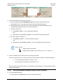
2.2.7 Ground Connector
The #10-32 stud shown in Figure 2-5 provides connection of a common chassis ground
among equipment.
Figure 2-5. LPOD-R Ground Connector Locations
2–9
LPOD-R Outdoor Amplifier / Block Up Converter
System Connections, Installation and Startup
2.3
MN-LPODR
Revision 1
Single Thread (Standalone) LPOD-R Installation
Kits are available from Comtech EF Data to mount and install a standalone LPOD-Rs, depending
on the type of unit ordered and its operational frequency.
Figures on the pages that follow illustrate available standalone mounting kits:
FIGURE
CEFD PART NO.
DESCRIPTION
2-6
PL/12319-1
Universal Pole Mounting Kit
2-7
KT-0000095
LPOD-R PS 1/PS 1.5 Single Unit Mounting Kit
Refer to Appendix A. CABLE DRAWINGS for information pertaining to the cables that are
available for use with the LPOD-R in standalone operation.
Figure 2-6. PL/12319-1 Universal Pole Mounting Kit
ITEM QTY
CEFD PART NO.
DESCRIPTION
1
1
N/A
BRACKET, UNISTRUT (SHOWN FOR CLARITY ONLY,
INCLUDED SEPARATELY IN CEFD MOUNTING KIT, e.g.,
P/N FP/BR0078, PART OF P/N KT-0000095)
2
1
FP/BR0072
BRACKET, STRAP TENSIONER
3
1
FP/BR0070
BRACKET, STRAP-TERMINATION POLE MOUNTING KIT
4
1
FP/BR0071
BRACKET, 1-1/4 STRAP (TRIM LENGTH AS REQUIRED)
5
1
FP/BR0069
BRACKET, STRAP-FIXED, POLE MOUNTING KIT
2–10
LPOD-R Outdoor Amplifier / Block Up Converter
System Connections, Installation and Startup
ITEM QTY
MN-LPODR
Revision 1
CEFD PART NO.
DESCRIPTION
6
2
HW/M8X1.25X25HEXSS
BOLT, HEXHEAD, M8X1.25X25, SS
7
7
HW/M8FLATSS
WASHER, FLAT, M8 SS, METRIC
8
7
HW/M8LOCKSS
LOCK WASHER, SPLIT, M8, SS, METRIC
9
2
HW/M8SPRINGNUT
SPRINGNUT, M8X1.25
10
5
HW/M8X1.25MMHEXNUTSS NUT, HEX M8X1.25X16MM, SS
11
2
HW/BLK-PIPE2-8
PIPE, BLOCK
This kit accommodates a pole diameter (OD) of up to 13.00” (33.02 cm) maximum.
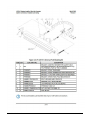
Figure 2-7. KT-0000095 LPOD-R PS 1, 1.5 Single Thread Mounting Kit
ITEM QTY
CEFD PART NO.
DESCRIPTION
1
1
FP-0000534
BRACKET, MOUNTING
2
1
FP/BR0078
BRACKET MODIFICATION POLE MOUNTING KIT
3
2
HW/1/4-20X1/2FH
SCREW, 1/4-20 X 1/2 FH PHIL, 82, UCUT, SS
4
2
HW-0000070
SCREW, HEX, SERR FLANGE HD, 3/8-16 x 3/4, SS
5
2
HW/3/8SPRINGNUT SPRINGNUT, 3/8-16, SHORT SPRING, SS (P3300)
2–11
LPOD-R Outdoor Amplifier / Block Up Converter
System Connections, Installation and Startup
2.4
MN-LPODR
Revision 1
Set the LPOD-R Power On
WARNING
For safety reasons, NEVER TURN THE UNIT ON WITHOUT PROPER WAVEGUIDE
TERMINATION ON THE J2 | RF OUT PORT. INDIVIDUALS CAN OTHERWISE BE
EXPOSED TO DANGEROUSLY HIGH ELECTROMAGNETIC LEVELS.
The LPOD-R does not contain a Power On/Off switch. It is powered ON by connecting the J3 |
POWER IN connector to the appropriate prime power source. The Mute or Transmit status of
the unit will automatically come up in the last stored state (factory default = Transmit on, not
muted).
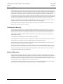
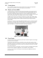
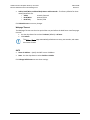
2.4.1 Monitoring LPOD-R Operation with the LED Indicator (PS .5 ONLY)
The LPOD-R PS .5 features a multi-color Light-Emitting Diode (LED) Indicator. Figure 2-8 shows
the location of this feature, on the signal output side of the LPOD-R PS .5 housing, next to the
ground lug. This LED provides you with visual cues to the operational status and LO setting for
the system.
Figure 2-8. LPOD-R PS .5 LED Indicator
A steadily-lit LED indicates that the unit is set for standard 14.0-14.5 GHz uplink frequency. A
blinking LED indicates that the unit is set for 13.75-14.5 GHz Tx frequency. Upon power-up of
the unit, the LED indicates operating status as per the following table:
OPERATING STATUS
LED COLOR
Green
Standard
Yellow
14.0-14.5 GHz Uplink Frequency
Red
Green (blinking)
13,.75-14.5 GHz Tx Frequency Operation Yellow (blinking)
Red (blinking)
2–12
UNIT STATE
Unmuted, 13.05 GHz LO
Muted, 13.05 GHz LO
Faulted, 13.05 GHz LO
Unmuted, 12.8 GHz LO
Muted, 12.8 GHz LO
Faulted, 12.8 GHz LO
Chapter 3. UPDATING FIRMWARE
3.1
Introduction
NOTE: For optimal performance, make sure to operate the LPOD-R with its
latest available firmware.
Comtech EF Data’s LPOD-R family of Outdoor Amplifiers / Block Up Converters (BUCs) are
factory-shipped with the latest version of operating firmware. You can apply the firmware
update to the LPOD-R without having to remove it from operation. If you need to update the
firmware, you can acquire the download from Comtech EF Data Product Support via e-mail or
on CD by standard mail delivery.
3.1.1 LPOD-R Firmware Update Process Summary
1. Download the firmware update archive file to a user-supplied PC. The PC must be
Microsoft Windows® compatible. It can be Comtech EF Data’s optional LPODnet. The
LPODnet is available for Ethernet-based remote monitor and control (M&C) of the
LPOD-R PS .5.
2. Connect a user-supplied Ethernet cable from the J9 | COM1 RJ-45 Ethernet port on the
LPOD-R PS.5 directly to the Ethernet port of the User PC. You can also use Comtech EF
Data’s optional CLC-10 Handheld Terminal M&C Accessory Kit (CEFD Kit KT-0020518) for
optional serial-based M&C of the LPOD-R PS 1 or PS 1.5.
3. Extract the firmware update files from the archive download file. Use the LPOD-R
Management IP Address to connect the FTP client to an FTP server. FTP transfer the files
from the User PC to the LPOD-R.
3.2
Prepare for the Firmware Download
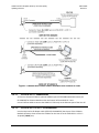
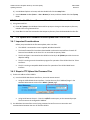
3.2.1 Required User-supplied Items
A Microsoft Windows-based PC equipped with available serial and Ethernet ports, a compatible
Web browser (e.g., Internet Explorer), and a terminal emulator program (e.g., Tera Term or
HyperTerminal). See Figure 3-1.
3–1
LPOD-R Outdoor Amplifier / Block Up Converter (BUC)
Updating Firmware
MN-LPODR
Revision 1
Figure 3-1. Monitor and Control Utilities Available from Comtech EF Data
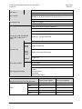
3.2.1.1
LPOD-R PS .5 connections
You can use Comtech EF Data’s optional LPODnet (part of CEFD M&C Netbook Accessory Kit
KT-0000203) for Ethernet-based monitor and control of the LPOD-R PS .5 unit.
Use an Ethernet cable to connect the LPOD-R PS .5 directly to the Ethernet port of the User PC.
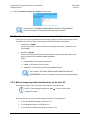
3.2.1.2
LPOD-R PS 1 or PS 1.5 connections
Use the 19 pin-to-RJ-45 adapter cable (CEFD P/N CA-0000352) that is part of the LPODnet
Netbook Accessory Kit to connect the LPODnet or the User PC to the LPOD-R PS 1 or PS 1.5
19-pin J6 | COM1 port,
3–2
LPOD-R Outdoor Amplifier / Block Up Converter (BUC)
Updating Firmware
MN-LPODR
Revision 1
You can use Comtech EF Data’s optional CLC-10 Handheld Terminal (part of CEFD M&C
Accessory Kit KT-0020518) for serial-based monitor and control of the LPOD-R PS 1 or PS 1.5
(when the optional EIA-232/485 serial interface is available). This kit provides an adapter cable
(CEFD P/N CA-0020526) to connect the CLC-10 to the PS 1 or PS 1.5 19-pin J6 | COM1 port.
You can use a user-fabricated 9 pin-to-19 pin adapter cable to directly connect the PC serial port
to the LPOD-R PS 1 or PS 1.5 19-pin J6 | COM1 port if you are using a user-supplied terminal
emulator program.
3.2.2 Configure the Terminal Emulator Program, if necessary
On the User PC – If not using the CLC-10, configure the terminal emulator program as necessary.
Refer to your terminal emulator program HELP feature or user guide for
operating and configuration instructions.
Configure the utility program serial port communication and terminal display operation:
38400 bps (Baud Rate)
8 Data Bits
1 Stop Bit
Parity = NO
Port Flow Control = NONE
Display New line Rx/Tx: CR
Local Echo = ON
3.2.3 Find the LPOD-R firmware and version numbers
1) On the LPOD-R – Set the power on for the unit. Your power connection varies depending on the unit
ordered.
See Chapter 2. SYSTEM CONNECTIONS, INSTALLATION AND
STARTUP in this manual for specific power connectors.
2) Find the firmware information using either of these methods:
3.2.3.1
•
To use the Web Server Interface, see Section 3.2.3.1.
•
To use the optional serial remote control, see Section 3.2.3.2.
Use the Web Server Interface to find the firmware version
1) Go to the Status | Summary page, or Go to Config | Utility page, Firmware Information section.
Or, go to the Status | Summary page.
3–3
LPOD-R Outdoor Amplifier / Block Up Converter (BUC)
Updating Firmware
MN-LPODR
Revision 1
2) Look at the Bootrom, Image1 and Image2 firmware loads.
See Chapter 4. ETHERNET-BASED REMOTE PRODUCT MANAGEMENT
for more information on using the LPOD-R Web Server Interface
3.2.3.2
Use the optional serial remote control to find the firmware version
Use the CLC-10 or a user-supplied terminal emulator program to execute remote queries with
the LPOD-R. Use either of these remote queries to find the firmware information:
•
Condensed : <0/SWR?
(returns the firmware version numbers running under Boot, Bulk1, and Bulk2, in the
form B.B.BB)
•
Detailed : <0/FRW?
(returns the complete information of the firmwares running under Boot, Bulk1, and
Bulk2 in the form FW- AAAAAAA B.B.BB DD/MM/YY,
where:
•
FW-AAAAAAA = the firmware part number
•
B.B.BB = the firmware version number
•
DD/MM/YY = the firmware release date (Day/Month/Year)
See Chapter 5. OPTIONAL SERIAL-BASED REMOTE PRODUCT
MANAGEMENT for more information on using remote commands/queries.
3.2.4 Make a temporary folder (subdirectory) on the User PC
The temporary folder is where you store the firmware archive download.
NOTE: These examples specify drive letter c:. You can use any valid,
writable drive letter.
There are several ways you can make a temporary folder on a Windows PC:
•
To use the Windows Desktop, see Section 3.2.1
•
To use Windows Explorer, see Section 3.2.2
•
To use the Run and Browse windows, see Section 3.2.3
3–4
LPOD-R Outdoor Amplifier / Block Up Converter (BUC)
Updating Firmware
•
MN-LPODR
Revision 1
To use Windows Command line, see Section 3.2.4
After you make the temporary folder, proceed to Section 3.3 to download and extract the
firmware files.
3.2.5 Use the Windows Desktop to make a temporary folder
Use the Windows Desktop to make and rename the temporary folder.
1. Right-click anywhere on the desktop to open the popup submenu.
2. Select New > Folder to make the new, temporary folder on the desktop.
3. Right-click on the new folder and then select Rename from the popup submenu.
4. Rename this folder to temp or some other convenient, unused name.
3.2.6 Use Windows Explorer to make a temporary folder
Use Windows Explorer to make and rename the temporary folder.
1. Select File > New > Folder to make the new, temporary folder in the active location.
2. Right-click the New Folder folder name, and then rename this folder to temp or some
other convenient, unused name.
3.2.7 Use the Run and Browse windows to make a temporary folder
Use the Run and Browse windows to make and rename the temporary folder.
1. Select Start on the Windows taskbar and then
2. Click Run… to open the Run window.
3. Click Browse… to open the Browse window.
3–5
LPOD-R Outdoor Amplifier / Block Up Converter (BUC)
Updating Firmware
MN-LPODR
Revision 1
4. Click New Folder. This can be an icon or a text label, depending on the Windows
version.
5. Name this new folder temp or some other convenient, unused name.
3.2.8 Use Windows Command line to make a temporary folder
1. Click Start on the Windows taskbar, and then click Run... to open the Run window.
•
Depending on Windows OS versions prior to Windows 95, click the MS-DOS
Prompt icon from the Main Menu.
•
Alternately, from Start, select All Programs > Accessories > Command Prompt.
2. Next, open a Command line window:
NOTE: Typical for many steps: Type the command, and then press Enter.
•
For Windows 95 or Windows 98 – enter command.
•
For any Windows OS versions later than Windows 98 – enter cmd or command.
3. Finally, from the Windows Command line c:\> prompt, type either:
•
mkdir temp or md temp
(both mkdir and md mean make directory).
4. Click OK.
3–6
LPOD-R Outdoor Amplifier / Block Up Converter (BUC)
Updating Firmware
3.3
MN-LPODR
Revision 1
Download and Extract the Firmware Update Files
3.3.1 About Firmware Numbers, File Versions, and Formats
The Comtech EF Data Web site catalogues its firmware update files by product type (e.g., router,
modem, etc.), the specific model, and optional hardware configurations.
The LPOD-R firmware download hyperlink appears as FW-0020841X-V### (for the LPOD-R PS .5)
or FW-0020880X_V### (for the LPOD-R PS 1 or PS 1.5).
NOTE: Where:
X
represents the revision letter
###
represents the firmware version number; e.g., V111 = Version 1.1.1
About File Archive Formats: Comtech EF Data provides its downloadable files in two compressed
archive formats: *.exe (self-extracting) and *.zip (compressed).
The *.exe file does not require a file archiver and compression utility program such as PKZIP for
Windows, WinZip, ZipCentral, etc. (PKZIP for DOS is not supported because of file naming
conventions). Comtech EF Data does not provide this utility program.
Some firewalls do not allow the download of *.exe files. Download the *.zip file instead, and
extract the firmware files from the archive download with a user-supplied utility program. For
detailed information on handling archived files, see the utility program Help documentation.
3.3.2 Steps to Download and Extract the Firmware Update Files
1) Download the firmware update file from the Comtech EF Data Web site:
a) Go online to www.comtechefdata.com.
b) On the Main page – Under Support Information or the Support tab, select the Software
Downloads hyperlink.
c) On the Software Downloads page – Click Download Flash and Software Update Files.
d) On the Flash Updates Index page – Select the (Select a Product Line) Amplifiers hyperlink.
e) On the Amplifiers product page – Select the LPOD-R product hyperlink;
f)
Select the appropriate firmware archive EXE or ZIP file download hyperlink.
g) Download the archive file to the temporary folder.
i)
Once you select the EXE or ZIP hyperlink, the File Download window opens and prompts
selection of Open or Save:
ii) Click Open to execute file extraction with a user-supplied utility program. Be sure to extract
the firmware files to the temp folder maked earlier.
iii) Click Save to open the Save As window. Select and Save the archive *.exe or *.zip file to the
temp folder maked earlier.
iv) Otherwise, click Cancel to quit and exit the file download process.
3–7
LPOD-R Outdoor Amplifier / Block Up Converter (BUC)
Updating Firmware
MN-LPODR
Revision 1
2) Extract the firmware files from the archive file.
a) (If not already done with File Download > Open) Extract the firmware files from the
downloaded *.exe or *.zip archive file with the user-supplied utility program:
b) Double-click on the archive file name, and then follow the prompts provided by the usersupplied utility program. Extract, at a minimum, two files:
c) FOR THE LPOD-R PS .5:
i)
FW-0020841X_###.bin – The Firmware Bulk image file
and
ii) ReleaseNotes_ FW-0020841X_V###.pdf – The Firmware Release Notes PDF file
d) FOR THE LPOD-R PS 1 OR PS 1.5:
i)
FW-0020880X_V###.bin – The Firmware Bulk image file
and
ii) ReleaseNotes_FW-0020880X_V###.pdf – The Firmware Release Notes PDF file file
NOTE: Where:
X
represents the revision letter
###
represents the firmware version number; e.g., V111 = Version 1.1.1
3) Confirm availability of the firmware files in the temporary folder.
There are several ways you can view the contents of the temporary folder on a Windows-based PC:
•
To use the Windows Desktop, see Section 3.3.2.1
•
To use Windows Command line, see Section 3.3.2.2
After you confirm the firmware files are in the folder, proceed to Section 3.4 to upload the firmware
update to the LPOD-R.
3.3.2.1
Use the Windows Desktop to see the folder contents
1) From the Windows Desktop:
a) Double-left-click the temp folder saved to the Windows Desktop.
3–8
LPOD-R Outdoor Amplifier / Block Up Converter (BUC)
Updating Firmware
MN-LPODR
Revision 1
b) Use Windows Explorer to locate, and then double-left-click the temp folder.
c) Use the Browse window (Start > ...Run > Browse) to locate, and then double-click the c:\temp
folder.
3.3.2.2
Use the Windows Command line to see the folder contents
1) Using Command line:
a) Enter cd c:\temp at the Windows Command line prompt to change to the temporary directory
maked earlier using Command line.
b) Enter dir to list the files extracted to the temporary directory from the downloaded archive file.
3.4
FTP Upload the Firmware Files and Update the LPOD-R Unit
3.4.1 Important Considerations
Before you proceed with the firmware update, make sure that:
•
The LPOD-R is connected to a user-supplied, Windows-based PC.
•
The latest firmware files have been downloaded or otherwise received from Comtech EF
Data and are available on the User PC in an accessible temporary folder.
•
The PC serial port is connected to the LPOD-R via the 19-pin J6 |COM1 port with the correct
adaptive cabling.
•
The PC is running a terminal emulation program for operation of the LPOD-R Serial or Telnet
interfaces.
•
The PC is running a compatible Web browser for operation of the LPOD-R Web Server
Interface.
3.4.2 Steps to FTP Upload the Firmware Files
1) Find the IP Address of the LPOD-R:
a) Use the LPOD-R Web Server Interface or, the serial remote control:
•
Using the LPOD-R Web Server Interface – look at the entry for IP Address/Range in the
Network Maintenance section of the Admin | Access page:
•
Using Serial Remote Control – Enter the <0/IPA? remote query at the command prompt.
The unit returns the configured IP Address.
2) Use Windows Command line to send a ping command to confirm correct connection and
communication between the User PC and the LPOD-R:
3–9
LPOD-R Outdoor Amplifier / Block Up Converter (BUC)
Updating Firmware
MN-LPODR
Revision 1
a) Ping the unit by entering ping xxx.xxx.xxx.xxx at the Windows Command line prompt. The
response should confirm whether the unit is connected and communicating correctly.
NOTE: Where:
xxx.xxx.xxx.xxx represents the assigned unit Management IP Address
3) Use Windows Command line to transfer the files from the User PC to the LPOD-R unit via FTP:
a)
Enter ftp xxx.xxx.xxx.xxx.
NOTE: Where:
xxx.xxx.xxx.xxx represents the assigned unit Management IP Address
b) Enter bin to set the binary transfer mode.
c) Enter prompt.
d) Enter hash.
e)
To begin the file transfer:
For the LPOD-R PS .5 only, enter put FW-0020841X.bin a:\bulk.bin:
or
For the LPOD-R PS 1 or 1.5,enter put FW-0020880X.bin a:\bulk.bin:
The destination a:\bulk.bin: must be all lower-case.
NOTE: Where:
f)
X
represents the revision letter
###
represents the firmware version number; e.g., V111 = Version 1.1.1
Wait for the file transfer to end.
g) Enter bye to stop the FTP session.
h) Close the Windows Command line window.
4) To verify that the PC-to-unit FTP file transfer was successful, find the current firmware information
via the serial or Ethernet interfaces (see Section 3.4.2, Step 1).
3.4.3 Steps to Update the LPOD-R Unit
Use the LPOD-R Web Server Interface to select the new firmware and soft-reboot the unit.
1) Select the desired Active Firmware Image:
a) Go to the Config | Utility page.
b) Use the Next Reboot Image drop-down list to select Image 1 or 2.
3–10
LPOD-R Outdoor Amplifier / Block Up Converter (BUC)
Updating Firmware
MN-LPODR
Revision 1
c) Click Submit.
2) Soft-reboot the LPOD-R:
a) In the Config | Utility page, Perform Soft Reboot section.
b) Click Reboot Now to reboot the LPOD-R with the Current Active Firmware Image.
c) Wait while the LPOD-R reboots.
3) To load a second image, repeat Step 1.
4) After the unit has rebooted with the new firmware, use serial remote control to enter the
<0/CTD=1? remote command to clear the trending data.
The LPOD-R is now operating with its latest firmware. The firmware update process is complete.
3.5
Recover the User Interface Access
The J9 | COM1 RJ-45 Ethernet port on the LPOD-R is the only means of access for monitor and
control (M&C) of the product. Loss of the unit’s Management IP Address or the interface access
credentials (the username/password and SNMP communities) prevents you from monitoring
and controlling the LPOD-R.
You can reset the access credentials for the LPOD-R. By issuing a ping command to IP Address
169.254.1.1 within the first 10 seconds of power cycle/reset of the unit, the LPOD-R resets its
access credentials to their factory default settings.
3.5.1 Recovery Steps Using a Windows PC.
1) Change the IP Address of the User PC NIC (the Network Interface Card that controls the Ethernet
port connected to the LPOD-R ) to 169.254.1.10:
a) On the Windows taskbar, Click Start and then click Control Panel.
b) From the Control Panel window, click the Network and Sharing Center icon.
c) Look for the View your active networks section of the Network and Sharing Center window.
d) Click the Local Area Connection hyperlink (e.g., Local Area Connection 2) to select the targeted
NIC.
e) In the Interface Status window, click Properties.
f)
If necessary, click the Network tab.
g) In the This connection uses the following items: window, select Internet Protocol Version
TCP/IPv4 .
3–11
LPOD-R Outdoor Amplifier / Block Up Converter (BUC)
Updating Firmware
MN-LPODR
Revision 1
IMPORTANT: Make sure that you do not uncheck the checkbox.
h) Click Properties.
i)
Enter the IP address: into the fields: 169 | 254 | 1 | 10
IMPORTANT: Make sure that you do not deselect the Use the following IP address:
radio button.
j)
Click OK to save the change.
2) If you have not already done so, connect a user-supplied Ethernet cable from the J9 | COM1 RJ-45
Ethernet port on the LPOD-R directly to the Ethernet port of the User PC.
3) Use Windows Command line to ping the actively running LPOD-R:
a) Enter ping -t 169.254.1.1 to begin repeatedly pinging the LPOD-R.
4) Cycle the LPOD-R power as the User PC continues to ping the unit.
5) Continue to observe the ping responses in the Windows Command line window.
6) Wait for one successful ping reply, followed by an unsuccessful ping – once the LPOD-R receives a
ping on IP address 169.254.1.1 within the first 10 seconds of the units power-up or reset, it restores
the interface access factory default values:
•
DEFAULT MANAGEMENT IP ADDRESS/RANGE – 192.168.1.4/24
•
DEFAULT WEB SERVER INTERFACE USERNAME – Comtech
•
DEFAULT WEB SERVER INTERFACE PASSWORD – comtech
7) As described in Step 1, change the IP address of the User PC’s assigned Ethernet port to an address
within the 192.168.1.XXX subnet (i.e., assign a Management IP Address to the LPOD-R from
192.168.1.001 through 192.168.1.255).
The LPOD-R management interface is now accessible and ready for M&C of the unit.
3–12
Chapter 4. ETHERNET-BASED
REMOTE PRODUCT
MANAGEMENT
4.1
Introduction
Ethernet remote monitor and control (M&C) of the LPOD-R PS .5 is available through its
100BaseT/10BaseTx Ethernet Management Interface by connecting the User PC Ethernet port to
the J6 | COM1 RJ-45 port on the LPOD-R.
Three protocols are available to use for Ethernet remote M&C. Operate these protocols
separately.
• Simple Network Management Protocol (SNMP). This requires a user-supplied Network
Management System (NMS) and a user-supplied Management Information Base (MIB) File
Browser.
• Telnet Interface. This requires use of the User PC’s Command line interface, or a usersupplied terminal emulation program, such as HyperTerminal.
• Web Server (HTTP) Interface. This requires a compatible user-supplied web browser such as
Internet Explorer.
4.1.1 Prerequisites
•
•
•
•
Before you proceed with Ethernet remote product management, make sure the following is
true:
The LPOD-R is operating with the latest version firmware files.
The User PC is running a terminal emulation program for operation of the LPOD-R Telnet
Interface.
The User PC is running a compatible web browser for operation of the LPOD-R Web Server
Interface.
The user-supplied Windows PC is connected to the LPOD-R as applicable:
o PS 0.5: The J6 | COM1 port on the unit connects to the User PC Ethernet port with a
user-provided Ethernet cable that has the available weatherproof connector kit (CEFD
P/N KT-0020707 or KT-0020708).
4–1
LPOD-R Outdoor Amplifier / Block Up Converter
Ethernet-based Remote Product Management
MN-LPODR
Revision 1
PS 1/1.5: The J6 | COM1 port on the unit connects to the User PC Ethernet port with the
available CA-0000352 Ethernet Interface Cable (part of CEFD Kit KT-0000203).
You have recorded the LPOD-R’s Management IP Address.
o
•
CAUTION
Comtech EF Data recommends use of the Ethernet-based SNMP interface for
advanced users only. All other users are strongly encouraged to use the LPOD-R web
server interface for remote Monitor and Control (M&C) of the LPOD-R.
4.2
SNMP Interface
SNMP is an Internet-standard protocol for managing devices over IP networks. An SNMP-managed
network has three key components:
• The managed device. This includes the LPOD-R.
• The SNMP Agent. This software runs on the LPOD-R. The LPOD-R SNMP Agent supports both
SNMPv1 and SNMPv2c.
• The user-supplied NMS. This software runs on the User PC.
4.2.1 Management Information Base (MIB) Files
An MIB file is used for SNMP remote management of a unique device, and consist of a tree of
nodes called Object Identifiers (OIDs). Each OID provides remote management of a particular
function. These MIB files should be compiled in a user-supplied MIB Browser or SNMP Network
Monitoring System server.
In these LPOD-R MIB file names,the letter x represents the revision of the file.
4.2.1.1
ComtechEFData Root MIB file
•
FW-0000291x.mib
•
ComtechEFData MIB file gives the root tree for all Comtech EF Data LPOD-R products (PSx) and
consists of only the following OID:
o
Name: comtechEFData
o
Type: MODULE-IDENTITY
o
OID: 1.3.6.1.4.1.6247
o
Full path: iso(1).org(3).dod(6).internet(1).private(4).enterprises(1).comtechEFData(6247)
Module: ComtechEFData
4–2
LPOD-R Outdoor Amplifier / Block Up Converter
Ethernet-based Remote Product Management
4.2.1.2
MN-LPODR
Revision 1
LPOD-R MIB file
•
FW-0000289x.mib
•
MIB file consists of all of the OID’s for management of the LPOD-R functions
4.2.1.3
LPOD-R Traps MIB file
•
FW-0000290x.mib
•
Trap MIB file provides SNMPv1 traps common for LPOD-R.
4.2.2 SNMP Community Strings
CAUTION
In SNMP v1/v2c, the SNMP Community String is sent unencrypted in the SNMP
packets. Caution must be taken by the network administrator to ensure that SNMP
packets travel only over a secure and private network if security is a concern.
The LPOD-R uses Community Strings as a password scheme that provides authentication before
gaining access to the router agent’s MIBs. They are used to authenticate users and determine
access privileges to the SNMP agent. The LPOD-R defines three Community Strings for SNMP
access:
• Read Community
default = public
•
Write Community
default = private
•
Trap Community
default = comtech
Type the SNMP Community String into the user-supplied MIB Browser or Network Node `
Management software.
For correct SNMP operation, the LPOD-R MIB files must be used with the associated
version of the LPOD-R M&C. See the LPOD-R FW Release Notes for information on
the required FW/SW compatibility.
4–3
LPOD-R Outdoor Amplifier / Block Up Converter
Ethernet-based Remote Product Management
4.3
MN-LPODR
Revision 1
Telnet Interface
4.3.1 Using the Telnet Interface for Remote Control Operation
Chapter 5. OPTIONAL SERIAL-BASED REMOTE PRODUCT MANAGEMENT
The LPOD-R has a Telnet interface for the purpose of equipment M&C via the optional Serial
Remote Control protocol. The Telnet interface requires user login at the Administrator level and
Read/Write level. An example of the login process is shown here:
Once logged into the Telnet interface as the Administrator, you have access to the optional serialbased Remote Control Interface as shown here:
4.3.2 Using HyperTerminal for Telnet Remote Control Operation
There is a disadvantage when using Windows Command line as a Telnet client with the optional
Remote Control protocol. For the messages coming from the Telnet Server, Command line
cannot translate a carriage return command (\r) to a carriage return + line feed command
(\r\n). Therefore, any multi-line Target-to-Controller response (e.g., the response to the FRW?
query) shows as one line, with the latter lines overwriting the previous lines.
4–4
LPOD-R Outdoor Amplifier / Block Up Converter
Ethernet-based Remote Product Management
MN-LPODR
Revision 1
To see the full response messages, you can use the HyperTerminal terminal emulation program
configured as a Telnet client.
Configure HyperTerminal as follows:
1. Make sure to define the Connect To Telnet connection properties correctly (File
Properties):
A) Enter the LPOD-R’s Traffic/Management IP Address as the Host address (e.g.,
192.168.1.1).
B) Enter TCP Port 23 as the Port number.
C) Set Connect using to TCP/IP (Winsock) instead of COM1 or COM2.
2. For ASCII Setup (File Properties Settings ASCII Setup):
A) Check the Send line ends with line feeds option in the ASCII Sending section.
B) Check the Append line feeds to incoming line ends option in the ASCII Receiving
section.
Examples of login and remote command/query execution, when using HyperTerminal as the
interface, follow:
4–5
LPOD-R Outdoor Amplifier / Block Up Converter
Ethernet-based Remote Product Management
MN-LPODR
Revision 1
4–6
LPOD-R Outdoor Amplifier / Block Up Converter
Ethernet-based Remote Product Management
4.4
MN-LPODR
Revision 1
Web Server (HTTP) Interface
A user-supplied web browser allows the full M&C of the LPOD-R through its Web Server
Interface. This embedded web application is designed for use with Microsoft’s Internet Explorer
Version 5.5 or higher. It is a non-secure web application.
See the Remote Commands and Queries specifications tables in Chapter 5. OPTIONAL SERIALBASED REMOTE PRODUCT MANAGEMENT for more information.
4.4.1 Enable the Web Server Interface
To enable the Web Server Interface in the LPOD-R using only a 100BaseTx remote interface
running a Microsoft Windows OS:
1. Select Start, then Run, then type
cmd.
2. Click OK to open the command
prompt window.
3. Start a Telnet session with the
unit at the default IP address of
192.168.1.4.
4. Enter the Telnet username and
password. The default for both
parameters is Comtech.
5. Set the remote access parameter
to accept Ethernet remote
control using the LRS command.
LRS=3, the default remote
command, provides Serial +
Ethernet control, while remote
command LRS=2 provides
Ethernet control only.
You must assign a unique IP Address for each unit on the network before connecting to an
existing network. The IP address may need to be changed from the factory default setting.
4–7
LPOD-R Outdoor Amplifier / Block Up Converter
Ethernet-based Remote Product Management
MN-LPODR
Revision 1
Use the command IPA=xxx.xxx.xxx.xxx.yy, where: xxx.xxx.xxx.xxx is a valid IP address on the
network where the unit is to be installed, and yy is the range (typically, yy = 24).
Changing the IPA value requires that you cycle power on the unit, and then start a new
Telnet session using the new IP address.
See Chapter 5 for more information on the LRS and IPA commands.
4.4.2 User Login
1. From the PC, enter the default IP address for the LPOD-R (e.g., http://192.168.1.4) into the
Address area of the browser.
2. In the Login window, type the User name and Password, and then click OK. The default User
Name and Password are both comtech.
Once the valid User Name and Password is accepted, the LPOD-R Web Server Interface
splash page shows. The Firmware Version in this example is subject to change.
4–8
LPOD-R Outdoor Amplifier / Block Up Converter
Ethernet-based Remote Product Management
MN-LPODR
Revision 1
4.4.3 Web Server Interface Operation
4.4.3.1
Menu Tree
This menu tree diagram shows the menus and pages in the LPOD-R Web Server Interface. This
interface has four top level navigation tabs, shown in blue. Each top level tab has secondary
level page hyperlinks (grey). Page hyperlinks open individual Web pages.
Home
Admin
Config
Status
Home
Access
Amplifier
Summary
Contact
SNMP
Utility
Status
Support
Events
Statistics
4.4.3.2
Page Navigation
The Web Server Interface has four navigation tabs at the top of each
page. Click a navigation tab to see its page hyperlinks. Click a page
hyperlink to open a page.
This manual uses a convention for all web pages to show you how to navigate to the referenced
page: Navigation Tab | Page Hyperlink.
For example, Home | Home means click the Home navigation tab, and then click the Home page
hyperlink.
4.4.3.3
Page Sections
Each page has one or more sections. The title at the upper-left corner
of each page or section describes its operational features. Each
section can have editable fields, action buttons and read-only
displays for a specific function. This manual explains the purpose and
operation for each Web page and its sections.
4.4.3.4
Action Buttons
Action buttons are important in the LPOD-R Web Server Interface. Click an
action button to do one of these tasks:
• Refresh the page with current data.
• Reset changed parameters to remove unsaved changes.
• Submit (save) changes.
If you change any parameters, make sure to click the related action button before you
leave the page. If you go to another page without first clicking the action button, your
changes are not saved.
4–9
LPOD-R Outdoor Amplifier / Block Up Converter
Ethernet-based Remote Product Management
4.4.3.5
MN-LPODR
Revision 1
Drop-down Lists
A drop-down list lets you choose from a list of selections. Left-click the
drop-down button to open the list. Then, left-click on an item to select
that choice.
4.4.3.6
Text or Data Entry
Text boxes let you type data into a field. An action button can be
associated with a single text box, or a group of text boxes.
For any text box, left-click anywhere inside the box and type the desired data into that field.
Make sure to press ENTER when done typing.
Click the related action button to save the data.
4.4.4 Home Pages
4.4.4.1
Home | Home
Use this page to identify the product. Click the Home navigation tab or the page hyperlink to
return to this page from anywhere in the Web Server Interface.
Figure 4-1. LPOD-R .5 Unit Home Page
4.4.4.2
Home | Contact / Home | Support pages
For all product support, please call:
+1.240.243.1880
+1.866.472.3963 (toll free USA)
4–10
LPOD-R Outdoor Amplifier / Block Up Converter
Ethernet-based Remote Product Management
MN-LPODR
Revision 1
4.4.5 Admin Pages
The Admin pages are available only to users who have logged in using the
Administrator Name and Password.
Use these administrator pages to set up user access.
4.4.5.1
Admin | Access
Refresh the page to see the latest data.
Figure 4-2. Admin | Access Page
Network Maintenance
•
IP Gateway, IP Address/Range – Enter the desired IP Gateway Address and IP Address/
Range in these text boxes.
•
MAC Address (read-only) – The MAC is set at the factory to a guaranteed unique address
that you cannot modify.
Click Change IP Address to save any changes.
System Account Access Information
Name fields can be any alphanumeric combination with a maximum length of 10 characters.
Password fields can be any alphanumeric combination with a maximum length of 10 characters.
4–11
LPOD-R Outdoor Amplifier / Block Up Converter
Ethernet-based Remote Product Management
•
MN-LPODR
Revision 1
Admin, Read/Write, and Read Only Names and Passwords – The factory defaults for these
names/passwords are:
o Admin
comtech/comtech
o Read/Write
opcenter/1234
o Read Only
monitor/1234
Click Submit Access to save any changes.
Webpage Timeout
The Webpage Timeout sets the time period that can pass before the Web Server Interface pages
time out.
• Use the drop-down list to select 5 minutes (default) or 8 hours.
• Click Submit.
The Status | Status page automatically refreshes once every ten seconds, and resets
the timeout counter.
SNTP
•
•
Server IP Address – Specify the SNTP server IP Address.
State - Use the drop-down to select Enable or Disable.
Click Change SNTP Params to save these settings.
4–12
LPOD-R Outdoor Amplifier / Block Up Converter
Ethernet-based Remote Product Management
4.4.5.2
MN-LPODR
Revision 1
Admin | SNMP
The Administrator must use this page to manage LPOD-R SNMP (Simple Network Management
Protocol) settings. Refresh the page to see the latest data.
Figure 4-3. Admin | SNMP Page
•
•
•
•
•
•
•
•
•
Simple Network Management – Use the drop-down list to select Enabled or Disabled.
The Read Community String and Write Community String fields can be any combination of
characters and a length of 0 to 20 characters.
o Read Community String factory default is public.
o Write Community String factory default is private.
SNMP Contact – Enter the contact data.
SNMP Name – Enter the name.
SNMP Location – Enter the location.
Enable Authentication Trap – Use the drop-down list to select Enabled or Disabled.
The Administrator can assign up to two SNMP Trap IP addresses.
Trap Version – Use the drop-down list to select the version.
The SNMP Trap Community String field can be any combination of characters and a length
of 0 to 20 characters. The factory default for the SNMP Trap Community String is comtech.
Click Submit SNMP to save any changes.
4–13
LPOD-R Outdoor Amplifier / Block Up Converter
Ethernet-based Remote Product Management
MN-LPODR
Revision 1
4.4.6 Config Pages
Use the Configuration pages to configure all operating parameters for the LPOD-R.
4.4.6.1
Config | Amplifier
Use this page to configure the communications, operations and alarms/faults handling for the
amplifier. Refresh the page to see the latest data.
Figure 4-4. Config | Amplifier Page
Amplifier
•
•
•
Attenuation (dB) – Enter a valid attenuation level (00.00 to 20.00 dB) in 0.25 dB steps.
Fault Recovery – Use the drop-down list to select Automatic or Manual.
User Mute – Use the drop-down list to select Enabled or Disabled.
Click Change Configuration to save any changes.
Low Forward Power Threshold (dBm)
Set the threshold value, in dBm, for the low forward power alarm/fault.
When the forward power monitor is set to Alarm or Fault instead of the factory default of Mask,
and the forward power drops below the specified value, the alarm/fault occurs.
To disable the threshold, set this parameter to the default value of 00.00.
Click Change to save any changes.
4–14
LPOD-R Outdoor Amplifier / Block Up Converter
Ethernet-based Remote Product Management
MN-LPODR
Revision 1
FSK Address
Set the FSK (Frequency Shift Keying) Address from 01 to 15.
Click Change to save any changes.
4.4.6.2
Config | Utility
Use this page to configure additional LPOD-R operating parameters. Refresh the page to see the
latest data.
Figure 4-5. Config | Utility Page
Date and Time
•
Enter a date using international format in the form DD/MM/YY (where DD = day [01 to 31],
MM = month [01 to 12], and YY = year [00 to 99]).
•
Enter a time using HH:MM:SS format (where HH = hour [00 to 23], MM = minutes [00 to 59],
and SS = seconds [00 to 59]).
Click Change Date/Time to save the changes.
Circuit ID
Enter a Circuit ID string of up to 48 characters. This is the identification label for the unit.
Click Change CID to save the change.
4–15
LPOD-R Outdoor Amplifier / Block Up Converter
Ethernet-based Remote Product Management
MN-LPODR
Revision 1
Current Active Firmware Image # (read-only)
The selected Current Active Firmware Image is shown here. In this example, Image 1 is the
Current Active Firmware Image.
Next Reboot Image
Use the drop-down list to select the Next Reboot Image as Image 1 or 2.
Click Submit to save the change.
Perform Soft Reboot
Click Reboot Now to reboot the LPOD-R using the Current Active Firmware Image.
Firmware Information (read-only)
This read-only window shows information about the currently loaded Bootrom. For the
complete Bulk1 and Bulk2 information, scroll through all the constituent firmware blocks that
make up the bulk.
Part Number (read-only)
This read-only window shows part number information for the unit.
4–16
LPOD-R Outdoor Amplifier / Block Up Converter
Ethernet-based Remote Product Management
MN-LPODR
Revision 1
4.4.7 Status Pages
Use these pages to see the unit’s operational status, logged alarm and statistics windows.
4.4.7.1
Status | Summary
This read-only page shows a summary of information about the LPOD-R unit and its current
operating state. Refresh the page to see the latest data.
Figure 4-6. Status | Summary Page
Summary (read only)
The Summary Fault message shows OK on a green background if no faults are present. If a fault
exists, the message changes to FAULT on a red background. Should this occur, look at the logged
faults and alarms on the Status | Events page.
Terminal Status Change
If Terminal Status Change shows NO, there have been no changes in the unit’s configuration
since the last time the Terminal Status Change status was cleared.
If Terminal Status Change shows YES, a status change had occured for one or more of these
reasons:
• An operating parameter changed, (e.g., when a command changes an operational value)
• A fault condition occurs
• A redundant switchover occurs
To reset the Terminal Status Change from YES to NO, click Clear.
4–17
LPOD-R Outdoor Amplifier / Block Up Converter
Ethernet-based Remote Product Management
4.4.7.2
MN-LPODR
Revision 1
Status | Status
Use this read-only page see general status data for the LPOD-R.
Unlike the pages that you must refresh manually, the Status | Status page updates
automatically once every 10 seconds. You can still refresh the page manually, if desired.
Figure 4-7. Status | Status Page
4–18
LPOD-R Outdoor Amplifier / Block Up Converter
Ethernet-based Remote Product Management
4.4.7.3
MN-LPODR
Revision 1
Status | MOP
Use this read-only page to see details of the unit’s Maximum Operating Point (MOP) data.
Refresh the page to see the latest data.
Figure 4-8. Status | MOP Page
4–19
LPOD-R Outdoor Amplifier / Block Up Converter
Ethernet-based Remote Product Management
4.4.7.4
MN-LPODR
Revision 1
Status | Events
Use this page to see stored events data. Additionally, use it to set the parameters for how the
LPOD-R triggers events and alarms. Refresh the page to see the latest data.
Figure 4-9. Status | Events Page
Unread Stored Events
This window shows the unread stored events log in sequential, date-stamped format. The unit
shows the five oldest stored events in the alarm log. A running tally of the number of unread
stored events shows in the window header. All events that are read from the log are removed
from the log automatically.
•
•
•
Select Read Next Five Events to show the next five unread stored events in the log.
Select Clear Events Log to clear all stored events from the log.
Select Initialize Events Pointer to reset the internal pointer to allow queries to start at the
beginning of the stored events log.
Click Submit to update the window according to your selection.
Alarm Mask
Use the drop-down list to select the Low Forward RF Power alarm as Fault, Alarm, or Masked.
Click Change Alarm Mask to save these settings.
4–20
LPOD-R Outdoor Amplifier / Block Up Converter
Ethernet-based Remote Product Management
4.4.7.5
MN-LPODR
Revision 1
Status | Statistics
This page shows all unread, stored statistics. Use it to configure how the LPOD-R handles and
shows statistics. Refresh the page to see the latest data.
Figure 4-10. Status | Statistics Page
Unread Stored Statistics: ###
This window shows the unread stored statistics log in sequential, date-stamped format. This
page shows a running tally of the number of unread stored statistics in the window header. The
unit shows the five oldest stored statistics. All events that are read from the log are removed
from the log automatically.
•
•
Select Read Next Five Statistics to cause the unit to return the oldest five unread stored
statistics that remain unread in the log. If fewer than five events are available for retrieval,
the remaining positions are padded with zeros. If there are no new events, the counter in
the header reads 000.
Select Initialize Statistics Pointer to reset the internal pointer to allow queries to start at the
beginning of the statistics log.
Click Submit to update the window according to your selection.
Statistics Configuration
•
•
Statistics Interval – Enter the interval at which statistics are logged. The interval is set in
minutes. Minimum resolution is 1 minute (001); maximum is 99 minutes (099). Default is 90
minutes (090).
Statistics Averaging – Select Enable or Disable to set the Statistics Averaging function:
4–21
LPOD-R Outdoor Amplifier / Block Up Converter
Ethernet-based Remote Product Management
o
o
MN-LPODR
Revision 1
If Enabled, statistics data is averaged at a rate of once per second for 10 seconds.
If Disabled, burst values are logged instead of averaged values.
Click Submit to save the changes.
4.4.7.6
Status | Trending Graphs
Use this page to see graphs showing trends over time for several operating parameters. You can
select the time settings for the graph also. Graphed operating parameters include:
• Amplifier Temperature
• Amplifier Output Power
• Line Voltage
• Line Current (Amp)
• Fan Voltage
• Fan Current (mA)
Refresh the page to see the latest data.
Figure 4-11. Status | Trending Graphs Example
Trending Graph Time Settings
• Start Date (mm/dd/yy) – Use the drop-down list to select present or a specific date.
• Time – If the Start Date is a specified date, select the starting Time for that date.
• Duration – Use the drop-down list to select a duration period for the graph statistics.
Click Submit to save the new settings.
4–22
LPOD-R Outdoor Amplifier / Block Up Converter
Ethernet-based Remote Product Management
MN-LPODR
Revision 1
Use the page scroll bar to see all of the trending graphs.
Figure 4-12. Status | Trending Graphs Example, continued
4–23
LPOD-R Outdoor Amplifier / Block Up Converter
Ethernet-based Remote Product Management
MN-LPODR
Revision 1
BLANK PAGE
4–24
Chapter 5. OPTIONAL SERIAL-BASED REMOTE
PRODUCT MANAGEMENT
NOTE: To ensure optimal performance and to access the most current remote commands and queries, it is important to operate the
LPOD-R with its latest available firmware.
5.1
Overview
Optional Serial-based remote product management of Comtech EF Data’s LPOD-R family of Outdoor Amplifiers / Block Up Converters
(BUCs) is available using the LPOD-R PS 1 or PS 1.5’s J6 | COM1 19-pin communications port. This chapter summarizes key parameters
and procedures and their associated remote commands and queries, and provides detailed instructions for use of the serial remote
control communication command and query interface.
5.2
Key Operational Parameters / Common Commands and Queries)
For detailed information about the remote commands and queries mentioned here, see Section 5.4.
Key operational parameters and their associated remote commands and queries are as follows:
5–1
LPOD-R Outdoor Amplifier / Block Up Converter (BUC)
Optional Serial-based Remote Product Management
MN-LPODR
Revision 1
•
ATT – ATTenuator control. Execute the ATT command to attenuate the LPOD-R gain over its specified range.
•
MUT – MUTe status. Execute the MUT command to “software” mute the unit.
•
RMS – Retrieve Maintenance Status. Use this query to display voltages, fan speeds, heatsink temperature, output power monitor
reading, etc.
A power detector is provided to monitor the output power. It has a useful range of over 15 dB, referenced to the unit’s rated P1dB
point. Execute the RMS query to read its value.
•
RCS – Retrieve Configuration Status. This query displays the current attenuation, mute, amplifier, online, etc. status.
•
RAS – Retrieve Alarm Status. Execute the RAS query to read the unit’s current fault or alarm condition status.
The M&C system monitors certain key functions of the LPOD-R for proper operation. Should any of these parameters exceed
predetermined limits, the M&C system declares a fault. All fault conditions cause the status LED to illuminate RED and the unit to
mute.
The conditions that trigger a fault are:
o
BUC PLL Unlocked Fault – This fault is asserted when the LO PLL is unable to lock to the 10 MHz input reference. The fault is deasserted when the LO PLL locks to the input reference.
o
Thermal Shutdown Fault – This fault is asserted if the heatsink temperature exceeds +95°C. A 10°C hysteresis margin is
employed; the fault is therefore de-asserted when the heatsink temperature drops lower than +85°C.
o
Unaccepted Firmware Fault (UFF) – This fault is asserted if you reject the running active firmware image (i.e., when you execute
the FAR=R command), or when you do not promptly accept the firmware when running a new active firmware image.
The UFF is de-asserted once you accept the new firmware (i.e., when you execute the FAR=A command).
5–2
LPOD-R Outdoor Amplifier / Block Up Converter (BUC)
Optional Serial-based Remote Product Management
5.2.1
MN-LPODR
Revision 1
End-of-Life Commands
Certain commands/queries are being marked by Comtech EF Data as End-of-Life (EOL). Flagged <description>E in the Parameter Type
column (in the Remote Commands and Queries tables in Sect. 5.4), while these commands/queries are fully supported in the LPOD-R,
Comtech EF Data strongly recommends that you use their new equivalents for new implementations.
EOL-designated Command/Query (Page #)
5.3
New Command/Query (Page #)
Remarks
CAA (5-9)
CAE (5-9)
–
CUS (5-12)
N/A
This functionality is not included in any other
remote command/query
DAT (5-12)
DAY (5-13)
–
LNA (5-15)
RNE (5-21)
–
RET (5-20)
PNM (5-18)
The replacement query provides more exact unit
hardware information
RSN (5-23)
SNO (5-23)
–
Remote Control Protocol and Structure
The electrical interface is either an EIA-485 multi-drop bus (for the control of many devices) or an EIA-232 connection (for the control of a
single device), and data is transmitted in asynchronous serial form, using ASCII characters. Control and status information is transmitted in
packets, of variable length, in accordance with the structure and protocol defined in later sections.
5.3.1
EIA-485
For applications where multiple devices are to be monitored and controlled, a full-duplex (or 4-wire) EIA-485 is preferred. Half-duplex (2wire) EIA-485 is possible, but is not preferred.
In full-duplex EIA-485 communication there are two separate, isolated, independent, differential-mode twisted pairs, each handling
serial data in different directions. It is assumed that there is a Controller device (a PC or dumb terminal), which transmits data, in a
broadcast mode, via one of the pairs. Many Target devices are connected to this pair, which all simultaneously receive data from the
Controller. The Controller is the only device with a line-driver connected to this pair – the Target devices only have line-receivers
connected.
5–3
LPOD-R Outdoor Amplifier / Block Up Converter (BUC)
Optional Serial-based Remote Product Management
MN-LPODR
Revision 1
In the other direction, on the other pair, each Target has a Tri-Stateable line driver connected, and the Controller has a line-receiver
connected. All the line drivers are held in high-impedance mode until one (and only one) Target transmits back to the Controller.
Each Target has a unique address, and each time the Controller transmits, in a framed packet of data, the address of the intended
recipient Target is included. All of the Targets receive the packet, but only one (the intended) will reply. The Target enables its output
line driver, and transmits its return data packet back to the Controller, in the other direction, on the physically separate pair.
EIA-485 (Full Duplex) Summary:
5.3.2
Two differential pairs
One pair for Controller to Target, one pair for Target to Controller.
Controller-to-Target pair
Pair has one line driver (Controller), and all Targets have line-receivers.
Target-to-Controller pair
Pair has one line receiver (Controller), and all Targets have Tri-State drivers.
EIA-232
This is a much simpler configuration in which the Controller device is connected directly to the Target via a two-wire-plus-ground
connection. Controller-to-Target data is carried, via EIA-232 electrical levels, on one conductor, and Target-to-Controller data is carried
in the other direction on the other conductor.
5.3.3
Basic Protocol
Whether in EIA-232 or EIA-485 mode, all data is transmitted as asynchronous serial characters, suitable for transmission and reception
by a UART. The character format should be 8N1 (8 data bits, no parity, 1 stop bit). The baud rate may vary from 2400 to 38400 baud.
All data is transmitted in framed packets. The Controller is assumed a PC or ASCII dumb terminal, which is in charge of the process of
monitor and control. The Controller is the only device that is permitted to initiate, at will, the transmission of data. Targets are only
permitted to transmit when they have been specifically instructed to do so by the Controller.
All bytes within a packet are printable ASCII characters, less than ASCII code 127. In this context, the Carriage Return and Line Feed
characters are considered printable.
All messages from Controller-to-Target require a response – with one exception. This will be either to return data that has been requested by
the Controller, or to acknowledge reception of an instruction to change the configuration of the Target. The exception to this is when the
Controller broadcasts a message (such as Set time/date) using Address 0, when the Target is set to EIA-485 mode.
5–4
LPOD-R Outdoor Amplifier / Block Up Converter (BUC)
Optional Serial-based Remote Product Management
5.3.4
MN-LPODR
Revision 1
Packet Structure
Controller-to-Target
Instruction Code
A-Z, a-z
ASCII codes 65-90,
97-122
(3 characters)
Code Qualifier
= or ?
ASCII codes
61 or 63
(1 character)
Optional Arguments
End of Packet
Carriage Return
ASCII code 13
(n characters)
(1 character)
Address Delimiter
/
ASCII code 47
Target-to-Controller
Instruction Code
A-Z, a-z
ASCII codes 65-90,
97-122
Code Qualifier
=, ?, !, or *
ASCII codes
61,63,33 or 42
Optional Arguments
(From 0 to n
characters)
(1 character)
(3 characters)
(1 character)
End of Packet
Carriage Return,
Line Feed
ASCII codes
13,10
(2 characters)
Start of Packet
<
ASCII code 60
Target Address
0-9
ASCII codes 48-57
Address Delimiter
/
ASCII code 47
(1 character)
(4 characters)
(1 character)
Start of Packet
>
ASCII code 62
Target Address
0-9
ASCII codes 48-57
(1 character)
(4 characters)
Example: <0412/MUT=1{CR}
Example: >0412/MUT=1{CR}{LF}
5.3.4.1
Start of Packet
These characters are used to provide a reliable indication of the start of packet. They must not appear anywhere else in the body of the
message:
•
•
Controller-to-Target: < (ASCII code 60)
Target-to-Controller: > (ASCII code 62)
5–5
LPOD-R Outdoor Amplifier / Block Up Converter (BUC)
Optional Serial-based Remote Product Management
5.3.4.2
MN-LPODR
Revision 1
Target Address
Up to 9,999 devices can be uniquely addressed. In EIA-232 applications, this value is set to 0. In EIA-485 applications, the permissible
range of values is 1 to 9999.
The Controller sends a packet with the address of a Target – the destination of the packet. When the Target responds, the
address used is the same address, to indicate to the Controller the source of the packet. The Controller does not have its
own address.
5.3.4.3
Address Delimiter
•
5.3.4.4
Forward slash character: / (ASCII code 47)
Instruction Code
This three-character alphabetic sequence is intended to be a mnemonic of its operational function. This aids in the readability of the
message, should you display it in its raw ASCII form.
For Example: GAC means Global Amplifier Configuration; IPA means IP Address, etc.
Both upper case and lower case alphabetic characters may be used (A-Z and a-z, ASCII codes 65-90 and 97-122).
5.3.4.5
Instruction Code Qualifier
This single character further qualifies the preceding instruction code. Code Qualifiers obey the following rules:
From Controller-to-Target, the instruction code qualifiers are:
=
(ASCII
code 61
This qualifier is used as the command (assignment) operator that instructs that the preceding instruction code should be set to the
value of the argument(s) that follow. For example: MUT=1 means ‘set the Mute function to Enabled’.
?
(ASCII
code 63)
This qualifier is used as the query operator that instructs the Target to return (report) to the Controller the current set value for the
parameter defined by the preceding instruction code. For example: SWR? means ‘return the firmwares installed in the Active and
Pending images’.
5–6
LPOD-R Outdoor Amplifier / Block Up Converter (BUC)
Optional Serial-based Remote Product Management
MN-LPODR
Revision 1
From Target-to-Controller, the instruction code qualifiers are:
=
(ASCII
code 61)
This qualifier displays in two ways:
1. First, if the Controller issues a command to set a parameter to a particular value, and the sent argument value is valid, then
the Target accepts the command by replying with, for example, MUT= (with no message arguments).
2. Second, if the Controller issues a query to a Target (for example, MUT?, meaning ‘is the Mute enabled or disabled?’), then
the Target responds to the query with MUT=x (where ‘x’ represents the configured state – e.g., ‘1’ being ‘enabled’ and ‘0’
being ‘disabled’).
?
(ASCII
code 63)
This qualifier displays only if the Controller issues a command to set a parameter to a particular value, but the sent argument value is
not valid. The Target rejects the command and responds to the error by echoing the instruction code, followed by the ‘?’ qualifier, with
no message arguments. Example: MUT?
!
(ASCII
code 33)
This qualifier displays only if the Controller issues an instruction code that the Target does not recognize. The Target rejects the
instruction code and responds to the error by echoing the invalid instruction code, followed by the ‘!’ qualifier, with no message
arguments . Example: XYZ!
*
(ASCII
code 42)
This qualifier displays only if the Controller issues a command to set a parameter to a particular value but – even though the argument
value is valid – the Target is in the wrong mode (e.g., Local mode instead of Remote mode) and does not permit that particular
parameter to be changed at that time. The Target rejects the command and responds to the error by echoing the instruction code,
followed by the ‘*’ qualifier, with no message arguments. Example: MUT*
#
(ASCII
code 35)
This qualifier displays only if the Controller sends an instruction code that the Target cannot currently perform due to hardware
resource issues – specifically, if you issue two or more ‘hardware configuration’ type commands without allowing adequate time,
between commands, for the hardware to be configured. If this happens, the Target rejects the instruction code and responds to the
error by echoing the invalid instruction, followed by the # character. For example, if you issue commands to change both the
frequency (FRQ=) and the attenuation (ATT=) with less than 100 milliseconds between the commands, and the Target responds with
ATT#, this means that the attenuation command was rejected and you must resend that command.
5.3.4.6
Optional Message Arguments
Arguments are not required for all messages. Arguments are ASCII codes for any printable character.
5.3.4.7
End of Packet
•
•
Controller-to-Target: This is the carriage return character (ASCII code 13).
Target-to-Controller: This is the two-character sequence of carriage return (ASCII code 13) and line feed (ASCII code 10).
Both indicate the valid termination of a packet.
5–7
LPOD-R Outdoor Amplifier / Block Up Converter (BUC)
Optional Serial-based Remote Product Management
5.4
MN-LPODR
Revision 1
Remote Commands and Queries
Column C = Command; Column Q = Query; columns marked X designate instruction code as Command only, Query only, or
Command/Query.
Where an Instruction Code is noted in this table as XXXE (and where the Parameter Type column is in the format <description>E), this
denotes the command/query as End of Life (EOL). See Sect. 5.2.1 for more information.
CODE
AFR
ATT
C Q
X X
X X
CAAE
CAE
CAS
CCS
CID
CMS
CUSE
X
X
DATE
DAY
X
X
ESA
X
X
PAGE
5–9
5–9
X
X
X
X
X
5–9
5–9
5–10
5–11
5–11
5–12
5–12
X
X
5–12
5–13
X
5–13
CODE
FAR
FRW
GAC
IEP
IPA
IPG
ISP
LNAE
LPT
LRS
C Q
X X
X
X
X
X
X
X
X
X
X
X
X
X
X
X
PAGE
5–13
5–14
5–14
5–14
5–15
5–15
5–15
5–15
5–16
5–16
CODE
MAC
MSK
MUT
C Q
X
X X
X X
X
X
NUE
NUS
PNM
RAS
RBT
RCS
RETE
RMS
RNE
RNS
RSNE
RUS
X
PAGE
5–17
5–17
5–17
5–18
5–18
X
5–18
X
5–18
5–19
5–19
5–20
5–20
5–21
5–22
5–23
5–23
X
X
X
X
X
X
X
5–8
CODE
SFA
SNO
SSI
SWR
TIM
TMP
TSC
C Q
X X
X X
X X
X
X
X
X
X
X
PAGE
5–23
5–23
5–23
5–23
5–24
5–24
5–24
Note: The following codes are used in the ‘Response to
Command’ column:
CODE MEANING
=
Message OK
?
Received OK, but invalid arguments found
*
Message OK, but not permitted in Current mode
#
Message OK, but only permitted in Remote mode
!
Unknown command
LPOD-R Outdoor Amplifier / Block Up Converter (BUC)
Optional Serial-based Remote Product Management
Parameter
Type
Auto Fault
Recovery
Command
(Instruction
Code and
Qualifier)
AFR=
Arguments
for Command
or Response
to Query
1 byte
MN-LPODR
Revision 1
Response to
Command
(Target to
Controller)
AFR=
AFR?
AFR*
Query
(Instruction
Code and
Qualifier)
AFR?
ATT=
ATT?
ATT*
ATT?
Example: <1/ATT=12.25’cr’
>0001/ATT=’cr’’lf’
Command only.
Instructs the unit to clear all Stored Alarms. This command takes no arguments.
CAA=
CAA*
N/A
N/A
Example: <1/CAA=’cr’
>0001/CAA=’cr’’lf’
Command only.
Instructs the BUC to clear all Stored Events. This command takes no arguments.
CAE=
CAE*
N/A
N/A
Description of Arguments
(Note that all arguments are printable ASCII characters)
Command or Query.
Enables or disables Auto Fault Recovery. The LPOD output is automatically muted if any of the following fault conditions
occur: BUC lock detect fault, LNB current fault (see Note), or LNB voltage fault (see Note). If enabled, auto fault recovery
causes the output to return to its pre-fault mute condition if all faults are cleared. If disabled, the output remains muted even
if all faults are cleared. Command/query is in the form x, where:
0 = Disable
1 = Enable
Response to
Query
(Target to
Controller)
AFR=x
(Same format as
command
arguments)
Default Value: 1
Example: <1/AFR=1’cr’
>0001/AFR=’cr’’lf’
Attenuation
ATT=
5 bytes
Note: This fault can be user-defined as fault, alarm, or masked (see MSK command for more info).
Command or Query.
Sets or returns the attenuation level, in dB, in the form xx.xx, where:
xx.xx = 00.00 to 20.00 in 0.25 dB steps.
(Same format as
command
arguments)
Default Value: 10.00
Clear All
Stored
AlarmsE
CAA=
Clear All
Stored
Events
CAE=
None
None
Example: <1/CAE=’cr’
>0001/CAE=’cr’’lf’
5–9
ATT=xx.xx
LPOD-R Outdoor Amplifier / Block Up Converter (BUC)
Optional Serial-based Remote Product Management
Parameter
Type
Concise
Alarm Status
Concise
Alarm Status
(cont)
Command
(Instruction
Code and
Qualifier)
N/A
Arguments
for Command
or Response
to Query
44 bytes
MN-LPODR
Revision 1
Description of Arguments
(Note that all arguments are printable ASCII characters)
Query only.
Returns the Alarm status of the unit. This is the concise version of the RAS command, response is semicolon delimited, in
the form a;b;c;d;e;f;g;h;i;j;k;I;m;n;o;p;q;r;s;t;u;v;w;x;y;z;aa’cr’’lf’ where:
a thru z = 0, 1, 2, 3, 4, or 5
0 = FT
1 = OK
2 = AL
3 = NO
4 = YS
5 = MS
a = LINEV
b = LINEA
c = LNB Power Supply (N/A)
d = +13.5V Power Supply (N/A)
e = +10V Power Supply
f = +10V1 Amplifier Power Supply
g = +10V2 Amplifier Power Supply (N/A)
h = +7.8V Power Supply (N/A)
i = +5.8V Power Supply
j= +2.5V Power Supply (N/A)
k = +1.2V Power Supply
l = -5V Power Supply
m = Fan1V
n = Fan1A
o = Heatsink Temp
p = Overtemp Shutdown
q = llC Status
r = Forward Power Alarm
s = Flash Checksum
t = FPGA Done (N/A)
u = BUC Lock Detect
v = External Ref Lock Detect (N/A)
w = LNB Current (N/A)
x = Redundant Switch Condition (N/A)
y = Redundant Link Status (N/A)
z = Terminal Status Change
aa = Unaccepted Firmware
Note: Field values appear only if the appropriate model/options are selected/installed. Otherwise, the unused fields display
NA.
5–10
Response to
Command
(Target to
Controller)
CAS=
Query
(Instruction
Code and
Qualifier)
CAS?
Response to
Query
(Target to
Controller)
CAS=x….x
(See Description
of Arguments for
details)
LPOD-R Outdoor Amplifier / Block Up Converter (BUC)
Optional Serial-based Remote Product Management
Parameter
Type
Concise
Configuration
Status
Circuit
Identification
Command
(Instruction
Code and
Qualifier)
N/A
CID=
Arguments
for Command
or Response
to Query
26 bytes
48 bytes
MN-LPODR
Revision 1
Description of Arguments
(Note that all arguments are printable ASCII characters)
Query only.
Returns the configuration status of the unit. This is the concise version of the RCS command, response is semicolon
delimited in the form aa.aa;b;c;d;e;ff.ff;g;hhh; ’cr’’lf’ where:
aa.aa = attenuation in dB (ATT)
b = RF power amplifier state (AMP):
0 = Off
1 = On
c = mute state (MUT):
0 = unmuted
1 = muted
d = online status (ONL)
e = redundancy state and mode (ESW)
ff.ff = Attenuator offset in dB (AOF)
g = auto fault recovery mode (AFR)
hhh = External reference status:
N/A = no external reference
05M for 5 MHz
10M for a 10 MHz (see Note)
Note: hhh is always N/A if the internal reference oscillator option is not installed.
Command or Query.
Sets or returns a user-defined string of data that may be used to identify or name the unit or station. The CID is a 48-byte
field of data that is entered as one line, but it is read back from the unit as two 24-byte lines of data.
Default Value:
------CID MESSAGE-----------------------------Example 1:
<1/CID= Station #001--SSPA #01--’cr’
>0001/CID=
Example 2:
<1/CID?’cr’
>0001/CID=’cr’
Station #001’cr’
--SSPA #01--’cr’’lf’
5–11
Response to
Command
(Target to
Controller)
CCS=
Query
(Instruction
Code and
Qualifier)
CCS?
Response to
Query
(Target to
Controller)
CCS=x….x
(See Description
of Arguments for
details)
CID=
CID?
CID*
CID?
CID=x…x
(See Description
of Arguments for
details.)
LPOD-R Outdoor Amplifier / Block Up Converter (BUC)
Optional Serial-based Remote Product Management
Parameter
Type
Concise
Maintenance
Status
Command
(Instruction
Code and
Qualifier)
N/A
Concise
Utility Status
N/A
Set RTC
(Real-TimeClock) DateE
DAT=
Arguments
for Command
or Response
to Query
95 bytes
15 bytes
6 bytes
MN-LPODR
Revision 1
Description of Arguments
(Note that all arguments are printable ASCII characters)
Query only.
Returns the Maintenance status of the unit. This is the concise version of the RMS command, response is semicolon
delimited in the form aaa.a;bbb.b;ccc.c;ddd.d;eee.e;fff.f;ggg.g;hh.h;iii.i;jjj.j;kkk.k;lll.l;mmm.m; nnn.n;ooo.o;ppp.p; qqq.q;
rrr.r;sss.s;ttt.t;’cr’’lf’ where:
aaa.a = LINEV
bbb.b = LINEA
ccc.c = LNBVT
ddd.d = P13VT
eee.e = P10V1
fff.f = A10V1
ggg.g = A10V2
hhh.h = P7V8T
iii.i = P5V8T
jjj.j = P2V5T
kkk.k = P1V2T
lll.l = N5V8T
mmm.m = FAN voltage
nnn.n = FAN current
ooo.o = BUCVT
ppp.p = FWPWR
qqq.q = REFVT
rrr.r = LNBCS
sss.s = ATEMP
ttt.t = OTEMP
Note: Field values appear if the appropriate model/options are selected/installed. Otherwise, unused fields are padded
with X’s.
Query only.
Returns the Maintenance status of the unit, response is semicolon delimited in the form aaaa;bbbbb;ccc; ’cr’’lf’ where:
aaaa = Remote Unit Address (unused)
bbbbb = Remote Baud Rate (unused)
ccc = Reference oscillator tuning voltage DAC value (unused)
Note: Unused fields are padded with X’s.
Command or Query.
Sets or returns the date in the form mmddyy, where:
mm = month of the year, between 01 and 12
dd = day of the month, between 01 and 31
yy = year, between 00 and 96 (2000 to 2096)
Response to
Command
(Target to
Controller)
CMS=
5–12
Response to
Query
(Target to
Controller)
CMS=x….x
(See Description
of Arguments for
details)
CUS=
CUS?
CUS=x….x
(See Description
of Arguments for
details)
DAT=
DAT?
DAT*
Example (date = April 24, 2013):
<1/DAT=042413’cr’
>0001/DAT=’cr’’lf’
Query
(Instruction
Code and
Qualifier)
CMS?
DAT?
DAT=mmddyy
(Same format as
command
arguments)
LPOD-R Outdoor Amplifier / Block Up Converter (BUC)
Optional Serial-based Remote Product Management
Parameter
Type
Set RTC
(Real-TimeClock) Date
Enable
Statistics
Averaging
Command
(Instruction
Code and
Qualifier)
DAY=
ESA=
Arguments
for Command
or Response
to Query
6 bytes
1 byte
MN-LPODR
Revision 1
Description of Arguments
(Note that all arguments are printable ASCII characters)
Command or Query.
Sets or returns the date in the form ddmmyy, where:
dd = day of the month, between 01 and 31
mm = month of the year, between 01 and 12
yy = year, between 00 and 99 (2000 to 2099)
Example (date = April 24, 2013):
<1/DAY=240413’cr’
>0001/DAY=’cr’’lf’
Command or Query.
Enables or Disables averaging of statistics data at a rate of once per second for 10 seconds. If Disabled, burst values will
be logged instead of averaged values. Command/query is in the form x, where:
0 = Disable
1 = Enable
Response to
Command
(Target to
Controller)
DAY=
DAY?
DAY*
Query
(Instruction
Code and
Qualifier)
DAY?
ESA=
ESA?
ESA*
ESA?
FAR=
FAR?
FAR*
FAR?
Response to
Query
(Target to
Controller)
DAY=ddmmyy
(Same format as
command
arguments)
ESA=x
(Same format as
command
arguments)
Default Value: 0
Firmware
Accept /
Reject
FAR=
1 byte
Example: <1/ESA=0’cr’
>0001/ESA=’cr’’lf’
Command or Query.
Accepts or Rejects the Active firmware Image in the form x, where:
A= Accept
R= Reject
Example: <1/FAR=A’cr’
>0001/FAR=’cr’’lf’
Notes:
1) Accept forces the LPOD-R to de-assert the Unaccepted Firmware Fault (UFF) generated by upload of the Pending
firmware Image to the Active firmware Image, and allows subsequent power-cycles/reboots to occur without affecting
the firmware image.
2) Reject causes the image to be erased on the next power cycle/reboot, and instructs bootmgr to wait until a new
firmware image load is FTPed into the Pending firmware Image.
5–13
FAR=x
(Same format as
command
arguments)
LPOD-R Outdoor Amplifier / Block Up Converter (BUC)
Optional Serial-based Remote Product Management
Parameter
Type
Retrieve
Firmware
Number
Command
(Instruction
Code and
Qualifier)
N/A
Global
Amplifier
Configuration
GAC=
Initialize
Events
Pointer
IEP=
Arguments
for Command
or Response
to Query
43 bytes
None
MN-LPODR
Revision 1
Description of Arguments
(Note that all arguments are printable ASCII characters)
Query only
Returns the firmware type(s) loaded into the unit in the form FW-AAAAAAA B.B.BB MM/DD/YY, where:
FW-AAAAAAA = the firmware part number
B.B.BB = the version number
MM/DD/YY = Month/Day/Year firmware released
Example:
<1/FRW?’cr’
>0001/FRW=’cr’’lf’
Activefirmware:
FW-0020765;1.1.1mx;03/19/14
Pendingfirmware:
PendingImage INVALID
Command or Query.
Sets or returns the global status of the BUC/SSPA, response is semicolon delimited in the form a;b;cc.cc;dd.dd;e;fffff;g;
hh;I;j;k;l;m;n;o;’cr’ where:
a = redundancy mode (ESW)
b = online status (ONL)
cc.cc = Attenuation Offset (AOF)
dd.dd = Customer Attenuation(ATT)
e = Auto Fault Recovery (AFR)
fffff = Unit Alarm Mask (MSK)
g = LNB Current Source (LCS)
hh = LNB Current Window (LCW)
i = LNB Current Window Enable (CWE)
j = Enable Statistics Averaging (ESA)
k = Set Statistics Interval (SSI)
l = Enable Statistics Logging (ESL)
m = Auxiliary Mute (AUX)
n = user mute state (MUT)
o = RF power amplifier state (AMP)
Note: Unused fields are padded with X’s.
Command only.
Resets internal pointer to allow RNE? queries to start at the beginning of the stored events log.
Example: <1/IEP=’cr’
>0001/IEP=’cr’’lf’
5–14
Response to
Command
(Target to
Controller)
FRW=
Query
(Instruction
Code and
Qualifier)
FRW?
Response to
Query
(Target to
Controller)
FRW=Activefirm
ware:{CR}abc{C
R}abc
Pendingfirmwar
e:{CR}abc{CR}a
bc
(See Description
of Arguments for
details)
GAC=
GAC*
GAC?
GAC#
GAC?
IEP=
IEP?
IEP*
N/A
GAC=x….x
(See Description
of Arguments for
details)
N/A
LPOD-R Outdoor Amplifier / Block Up Converter (BUC)
Optional Serial-based Remote Product Management
Parameter
Type
IP Address
Command
(Instruction
Code and
Qualifier)
IPA=
Arguments
for Command
or Response
to Query
18 bytes
MN-LPODR
Revision 1
Description of Arguments
(Note that all arguments are printable ASCII characters)
Command or Query.
Used to set the IP address and network prefix for the 10/100 BaseT Ethernet port, in the form
xxx.xxx.xxx.xxx.yy, where:
xxx.xxx.xxx.xxx = IP address
yy = network prefix (8-30)
Response to
Command
(Target to
Controller)
IPA=
IPA?
IPA*
IPA#
Query
(Instruction
Code and
Qualifier)
IPA?
Response to
Query
(Target to
Controller)
IPA=
xx.xxx.xxx.xxx.y
y (See
description of
arguments)
IPG=
IPG?
IPG*
IPG?
IPG =
xxx.xxx.xxx.xxx
ISP=
ISP?
ISP*
N/A
N/A
LNA=
LNA?
LNA=YY..ss
Default Value: 192.168.001.004.24
Example: <1/IPG=192.168.001.004.24’cr’
>0001/IPG=’cr’’lf’
Gateway
Address
IPG=
15 bytes
Note: Changing the IP address through the Telnet interface requires that you power cycle the unit, and then restart a new
Telnet session with the new IP address (do not include the network prefix, e.g., type in 192.168.1.4 only)
Command or Query.
Sets or returns the Gateway IP address for the 10/100 Base Tx Ethernet port, in the form xxx.xxx.xxx.xxx.
Default Value: 192.168.001.005
Initialize
Statistics
Pointer
ISP=
Retrieve next
5 unread
Stored
Alarms E
N/A
None
145 bytes
Example: <1/IPG=192.168.001.005’cr’
>0001/IPG=’cr’’lf’
Command only.
Resets the internal pointer to allow RNS? queries to start at the beginning of the stored statistics log.
Example: <1/ISP=’cr’
>0001/ISP=’cr’’lf’
Query only.
Returns the five oldest stored events in the alarm log in the form:
YYYYYYYYYY ZZ mmddyy hhmmss’cr’
YYYYYYYYYY ZZ mmddyy hhmmss’cr’
YYYYYYYYYY ZZ mmddyy hhmmss’cr’
YYYYYYYYYY ZZ mmddyy hhmmss’cr’
YYYYYYYYYY ZZ mmddyy hhmmss’cr’’lf’
Where:
YYYYYYYYYY = fault description.
ZZ = one of the following event types:
FT = Fault
OK = Clear
IF = Information
mmddyy hhmmss = date / time stamp.
5–15
(See Description
of Arguments for
details)
LPOD-R Outdoor Amplifier / Block Up Converter (BUC)
Optional Serial-based Remote Product Management
Parameter
Type
Retrieve next
5 unread
Stored
Alarms E
(cont)
Low forward
Power
Threshold
Command
(Instruction
Code and
Qualifier)
Arguments
for Command
or Response
to Query
LPT=
5 bytes
MN-LPODR
Revision 1
Description of Arguments
(Note that all arguments are printable ASCII characters)
Example: <1/LNA?’cr’
>0001/LNA=’cr’
LOG CLR IF 175503 052307’cr’
FAN #1 FT 175504 052307’cr’
OVR TMP FT 175504 052307’cr’
FAN #1 OK 175504 052307’cr’
IIC BUS FT 175504 052307’cr’’lf’
Notes:
1) If there are no events in the log the unit will reply with LNA*.
2) All events that are read from the log are also automatically removed from the log.
Command or Query.
Sets or returns the threshold for the low forward power alarm/fault in the form xx.xx.
Default Value: 00.00
Response to
Command
(Target to
Controller)
Query
(Instruction
Code and
Qualifier)
LPT =
LPT?
LPT *
LPT?
Local/Remote
State
LRS=
1 byte
LRS=
LRS?
LRS?
Default Value: 3 (Serial+Ethernet)
Example: <1/LRS=3’cr’
>0001/LRS=’cr’’lf’
Notes:
1) Use this command to limit changes from being made on multiple interfaces at the same time.
2) State is always in remote mode for Outdoor SSPAs such as the LPOD-R.
3) The LRS command is available in all modes as a means of acquiring control. You will always have query access in
any mode.
4) The LPOD-R treats LRS=0 as reserved, and refuses the command by returning a mode error.
5) The Web server interface is inoperable unless LRS is set to enable Ethernet remote control.
5–16
LPT =xx.xx
(Same format as
command
arguments)
Example: <1/LPT=00.00’cr’
>0001LPT=’cr’’lf’
Notes:
1) If there are no events in the log the unit will reply with LNA*.
2) All events that are read from the log are also automatically removed from the log.
3) Setting this parameter to 00.00 effectively disables the threshold
Command or Query.
Sets or returns the Local or Remote state for the Indoor SSPA in the form x, where:
0 = Local
1=Serial
2=Ethernet
3=Serial+Ethernet
Response to
Query
(Target to
Controller)
LRS=x
(Same format as
command
arguments)
LPOD-R Outdoor Amplifier / Block Up Converter (BUC)
Optional Serial-based Remote Product Management
Parameter
Type
Unit MAC
Address
Unit Alarm
Mask
Command
(Instruction
Code and
Qualifier)
N/A
MSK=
Arguments
for Command
or Response
to Query
17 bytes
5 bytes
MN-LPODR
Revision 1
Description of Arguments
(Note that all arguments are printable ASCII characters)
Query only.
Returns the MAC address of the unit, reported in hexadecimal format.
Example: <1/MAC?’cr’
>0001/MAC=00-06-B0-00-D2-A7’cr’’lf’
Command or Query.
Sets or returns alarm mask conditions. in the form abcde, where:
0 = Fault,
1 = Alarm
2 = Masked
a = Low Forward RF Power
b = External Reference Lock detect
c = Fan Speed
d = LNB Current Detect
e = LNB 22V Power Supply
Response to
Command
(Target to
Controller)
MAC=
Query
(Instruction
Code and
Qualifier)
N/A
MSK=
MSK?
MSK*
MSK?
MUT=
MUT?
MUT*
MUT?
Response to
Query
(Target to
Controller)
MAC=xx-xx-xxxx-xx-xx
(See Description
of Arguments for
details)
MSK=abcde
(See Description
of Arguments for
details)
Default Value: 22111
Example: <1/MSK=22111’cr’
>0001/MSK=1’cr’’lf’
Mute State
MUT=
1 byte
Notes:
1) If the mask value for a certain parameter is set to fault then a fault condition will be registered if specified hardware
conditions are not met.
2) If the mask value is set to alarm then a fault condition will only appear to be an alarm that will not trigger a switchover
in a redundant system.
3) If the mask value is set to masked then the fault will never be reported to the user
Command or Query.
Mute the unit in the form x, where:
0 = Disable (Not Muted)
1 = Enable (Muted)
2 = Unit muted due to AUX mute signal (Query response only – see Note)
Default Value: 1
Example: <1/MUT=1’cr’
>0001/MUT=1’cr’’lf’
Note: The value 2 displays only in response to a query and cannot be issued as a command. When MUT=2 this indicates
that an unexpected “hardware” mute condition is present. For example, an auxiliary mute could be present if the auxiliary
mute has been enabled and the signal to unmute the unit is not provided. Additionally, certain faults can generate a
hardware mute such as the BUC lock detect, the LNB current draw (if enabled by the user), or the LNB voltage (if enabled
by the user). If MUT=2, check the active faults and the status of the auxiliary mute.
5–17
MUT=x
(Same format as
command
arguments)
LPOD-R Outdoor Amplifier / Block Up Converter (BUC)
Optional Serial-based Remote Product Management
Parameter
Type
Number of
Unread
stored Events
Command
(Instruction
Code and
Qualifier)
N/A
Number of
Unread
stored
Statistics
N/A
Part Number
N/A
Retrieve
Alarm Status
N/A
Arguments
for Command
or Response
to Query
3 bytes
3 bytes
96 bytes
alphanumeric
168 bytes
MN-LPODR
Revision 1
Description of Arguments
(Note that all arguments are printable ASCII characters)
Query only.
Returns the number of stored events that remain unread, in the form xxx.
Example: <1/NUE?’cr’
>0001/NUE=126’cr’’lf’
Query only.
Returns the number of stored statistics that remain unread, in the form xxx.
Example: <1/NUS?’cr’
>0001/NUS=126’cr’’lf’
Query Only
Returns the DOTCODE string that was loaded into the unit.
Example: <1/PNM? ’cr’
>0001/PNM=HPODC0.350WRSW00’cr’’lf’
Query only.
Returns the Alarm status of the unit, where:
OK = no fault condition
FT = faulted
AL = alarm
YS = Yes
NO = No
MS = masked
NA = unused
Response to
Command
(Target to
Controller)
NUE=
Query
(Instruction
Code and
Qualifier)
NUE?
Response to
Query
(Target to
Controller)
NUE=xxx
NUS=
NUS?
NUS=xxx
PNM=
PNM?
PNM *
PNM?
PNM=x….x
RAS=
RAS?
(See Description
of Arguments for
details)
RAS=x….x
(See Description
of Arguments for
details)
Example:
<1/RAS?’cr’
>0001/RAS=’cr’
LINEV=OK’cr’ input LINE voltage
LINEA=OK’cr’ input LINE amperage
LNBVT=NA’cr’ +13/18V LNB power supply
P13VT=NA’cr’ +13.5V power supply
P10V1=NA’cr’ +10V power supply
A10V1=NA’cr’ +10V1 RF supply
A10V2=NA’cr’ +10V2 RF supply
P7V8T=NA’cr’ +7.8V power supply
P5V8T=OK’cr’ +5.8V power supply
P2V5T=NA’cr’ +2.5V power supply
P1V2T=OK’cr’ +1.2V power supply
N5V8T=AL’cr’ -5.8V power supply
FANV=OK’cr’ Fan voltage
FANA=OK’cr’ Fan current
ATEMP=OK’cr’ Amplifier temperature
5–18
LPOD-R Outdoor Amplifier / Block Up Converter (BUC)
Optional Serial-based Remote Product Management
Command
(Instruction
Code and
Qualifier)
Arguments
for Command
or Response
to Query
Reboot
RBT=
1 byte
Retrieve
Configuration
Status
N/A
45 bytes
Parameter
Type
Retrieve
Alarm Status
(cont)
MN-LPODR
Revision 1
Description of Arguments
(Note that all arguments are printable ASCII characters)
SHTDN=OK’cr’ Over-temp shutdown
IICST=OK’cr’ I2C bus status
FWPWR=MS’cr’ Forward power in dBm
CHKSM=OK’cr’ Flash checksum
FPGAD=NA’cr’ FPGA done status
BUCLD=OK’cr’ BUC lock detect
REFLD=NA’cr’ Reference lock detect
LNBCS=NA’cr’ LNB current status
SWITC=NA’cr’ Waveguide switch position status
RDLNK=NA’cr’ Redundant link status
TRMST=YS’cr’ Terminal Status
UNAFW=OK’cr’’lf’ Unaccepted Firmware
Note: Field values display when the appropriate model/options are selected/installed. Otherwise, unused fields display NA.
Command only.
Performs a Soft Reboot of the unit, where:
1 = Reboot System
Example: <1/RBT=’cr'
Query only.
Returns the configuration status of the unit, where:
ATT= attenuation, in dB
AMP= RF power amplifier state:
0=OFF
1=ON
MUT=RF mute state:
0=unmuted
1=muted
RED=Online status for redundancy
ESW=Redundancy state and mode state:
0=OFF
1=ON Tx only
2=ON Tx & Rx
AOF=Attenuator Offset, in dB
AFR= auto fault recovery
0 = manual
1 = auto
XRF = External reference status:
N/A = no external reference
05M = 5 MHz
10M = 10 MHz
Response to
Command
(Target to
Controller)
Query
(Instruction
Code and
Qualifier)
Response to
Query
(Target to
Controller)
RBT=
RBT?
RBT*
N/A
RBT=x
(See Description
of Arguments for
details)
RCS=
RCS?
RCS=x….x
(See Description
of Arguments for
details)
5–19
LPOD-R Outdoor Amplifier / Block Up Converter (BUC)
Optional Serial-based Remote Product Management
Parameter
Type
Retrieve
Configuration
Status (cont)
Command
(Instruction
Code and
Qualifier)
Retrieve
Equipment
Type E
N/A
Retrieve
Maintenance
Status
N/A
Arguments
for Command
or Response
to Query
22 bytes
213 bytes
alphanumeric
MN-LPODR
Revision 1
Description of Arguments
(Note that all arguments are printable ASCII characters)
Example:
<1/RCS?’cr’
>0001/RCS=’cr’
ATT=12.75’cr’
AMP=1’cr’
MUT=1’cr’
ONL=1’cr’
ESW=1’cr’
AOF=00.00’cr’
AFR=1’cr’
XRF=N/A’cr’’lf’ (see Note 2)
Notes:
1) Unused fields shall be padded with X’s.
2) XRF is always N/A when the internal reference oscillator option is not installed.
Query only.
Returns a string indicating the Model Number and the version of the installed M&C firmware.
Example: <1/RET?’cr’
>0001/RET=LPOD-R VER: 1.1.1’cr’’lf’
Query only.
Returns the maintenance status of the unit, where:
LINEV = LINE voltage
LINEA = LINE amperage
LNBVT = +13/18V LNB power supply (see Note)
P13VT = +13.5V power supply
P10V1 = +10V1 power supply
A10V1 = 10V1 on RF Module
A10V2 = 10V2 on RF Module (see Note)
P7V8T = +7.8V power supply
P5V8T = +5.8V power supply
P2V5T = +2.5V power supply
P1V2T = +1.2V power supply
N5V8T = -5.8V power supply
FAN1V = Fan 1 voltage
FAN1A = Fan 1 current
BUCVT = BUC tuning voltage (see Note)
FWPWR = Forward power in dBm
REFVT = Reference osc. tuning voltage (see Note)
LNBCS = LNB current supply in mA (see Note)
ATEMP = Heatsink temperature in Celsius
OTEMP = Outdoor temperature in Celsius (see Note)
Response to
Command
(Target to
Controller)
Query
(Instruction
Code and
Qualifier)
RET=
RET?
RET=x….x
RMS?
(See Description
of Arguments for
details)
RMS=x….x
RMS=
Response to
Query
(Target to
Controller)
(See Description
of Arguments for
details)
5–20
LPOD-R Outdoor Amplifier / Block Up Converter (BUC)
Optional Serial-based Remote Product Management
Parameter
Type
Retrieve
Maintenance
Status (cont)
Retrieve Next
5 unread
stored
Events
Command
(Instruction
Code and
Qualifier)
N/A
N/A
Arguments
for Command
or Response
to Query
213 bytes
alphanumeric
75 bytes
MN-LPODR
Revision 1
Description of Arguments
(Note that all arguments are printable ASCII characters)
Example: <1/RMS?’cr’
>0001/RMS=
LINEV=046.9
LINEA=000.3
LNBVT=XXXXX
P13VT=XXXXX
P10V1=010.5
A10V1=XXXXX
A10V2=XXXXX
P7V8T=XXXXX
P5V8T=006.1
P2V5T=XXXXX
P1V2T=001.3
N5V8T=-03.6
FAN1V=010.3
FAN1A=011.6
BUCVT=XXXXX
FWPWR=<24.0
REFVT=XXXXX
LNBCS=XXXXX
ATEMP=028.0
OTEMP=011.0
Note: LNBVT, FANR2, A10V2, BUCVT, REFVT, LNBCS, and OTEMP display when the appropriate options are installed;
Otherwise, the value fields shall be padded with X’s
Query only.
Unit returns the oldest 5 Stored Events that have not yet been read over the remote control. Reply format: {CR}Subbody{CR}Sub-body{CR}Sub-body{CR} Sub-body{CR}Sub-body, where Sub-body= ABCCddmmyyhhmmss:
A = Fault/clear indicator:
F=Fault
C=Clear
I=Info
B = Fault type:
1=Unit
2=RF
3=Log
CC = Fault Code numbers (as in RAS?) or Info Code:
0=Power Off
1=Power On
2=Log Cleared
3=Global Config Change
4=Redundancy Config Change
5–21
Response to
Command
(Target to
Controller)
Query
(Instruction
Code and
Qualifier)
RNE=
RNE?
Response to
Query
(Target to
Controller)
RNE={CR}ABC
Cddmmyyhhmm
ss{CR}ABCCdd
mmyyhhmmss{
CR}ABCCddmm
yyhhmmss{CR}
ABCCddmmyyh
hmmss{CR}ABC
Cddmmyyhhm
mss
(See Description
of Arguments for
details)
LPOD-R Outdoor Amplifier / Block Up Converter (BUC)
Optional Serial-based Remote Product Management
Parameter
Type
Retrieve Next
5 unread
stored
Events (cont)
Retrieve Next
5 unread
stored
Statistics
Command
(Instruction
Code and
Qualifier)
N/A
Arguments
for Command
or Response
to Query
75 bytes
Description of Arguments
(Note that all arguments are printable ASCII characters)
RAS fault codes map is as follows:
1)
2)
3)
4)
5)
6)
7)
8)
9)
10)
11)
12)
N/A
75 bytes
MN-LPODR
Revision 1
LINEV
LINEA
LNBVT
P13VT
A10V1
A10V2
10VPS
P5V8T
P2V5T
P1V2T
N5V8T
P7V8T
13)
14)
15)
16)
17)
18)
19)
20)
21)
22)
23)
24)
Query
(Instruction
Code and
Qualifier)
RNS=
RNS?
Response to
Query
(Target to
Controller)
FAN1V
FAN1A
ATEMP
SHTDN
IICST
FWPWR
CHKSM
FPGAD
BUCLD
REFLD
LNBCS
SWITC
Notes:
1) If there are less than 5 events to be retrieved, the remaining positions are padded with zeros.
2) If there are no new events, the response is RNE*.
3) A Global Config Change is defined as any time a command is successfully executed.
4) A query does not set the status change flag.
5) The status change flag is cleared after being read. No other events toggle a status change.
Query only.
Returns the oldest five stored statistics entries that have not yet been read, in the form: {CR}Sub-body{CR}Subbody{CR}Sub-body{CR}Sub-body{CR}Sub-body, where:
Sub-body= ddmmyyhhmmssaaa.abbb.bccc.cdd.ddefghhh.hiii.i, where:
ddmmyy = day/month/year
hhmmss = hour:minute:second
aaa.a = Operating Temperature (I.E. +40.0)
bbb.b = Amp Temperature (I.E. +40.0)
ccc.c = RF Power output
dd.dd = Attenuation Setting
e = Amp On/Off
f = Mute On/Off
g = Online/Offline Status
hhh.h = LNB Current (mA)
iii.i = BUC Tuning Voltage
Notes:
1) If there are less than five entries to be retrieved, the remaining positions are padded with zeros.
2) If there are no new entries, the response is RNS*.
5–22
Response to
Command
(Target to
Controller)
RNS={CR}Subbody{CR}Subbody{CR}Subbody{CR}Subbody{CR}Subbody
(See Description
of Arguments for
details)
LPOD-R Outdoor Amplifier / Block Up Converter (BUC)
Optional Serial-based Remote Product Management
Parameter
Type
Serial
Number E
Retrieve
Utility Status
Set FSK
Address
Command
(Instruction
Code and
Qualifier)
N/A
N/A
SFA=
Arguments
for Command
or Response
to Query
9 bytes
15 bytes
2 bytes,
numeric
MN-LPODR
Revision 1
Description of Arguments
(Note that all arguments are printable ASCII characters)
Query only.
Returns the unit’s 9 digit serial number in the form xxxxxxxxx.
Example: <1/RSN?’cr’
>0001/RSN=072282040’cr’’lf’
Query only.
Returns the utility status of the unit, response is comma delimited. Exists only for backward compatibility.
Example:
<1/RUS?’cr’
>0001/RUS=’cr’’lf’
ADR=XXXX
BDR=XXXXX
REF=XXX’cr’’lf’
Command or Query.
Sets or returns the FSK Address in the form xx, where:
xx = 01 to 15
Response to
Command
(Target to
Controller)
RSN=
RUS=
Query
(Instruction
Code and
Qualifier)
RSN?
Response to
Query
(Target to
Controller)
RSN=xxxxxxxxx
RUS?
(See Description
of Arguments for
details)
RUS=x….x
(See Description
of Arguments for
details)
SFA=
SFA?
SFA*
SFA?
SNO=
SNO?
(See Description
of Arguments for
details)
Default Value: 01
Serial
Number
N/A
9 bytes
Example: <1/SFA=01’cr’
>0001/SFA=’cr’’lf’
Query only.
Returns the unit’s nine-digit serial number in the form xxxxxxxxx.
SSI=
2 bytes
Note: This query is functionally identical to RSN.
Command or Query.
Sets or returns the interval at which statistics are logged in minutes, in the form xx, where:
xx =. 01 (min) to 99 (max)
SSI=
SSI?
SSI?
Software
Revision
N/A
34-37 bytes
SWR=
SWR?
Example: <1/SWR?’cr’
>0001/SWR=FW-0020765;1.1.1mx;03/19/14 PendingImage INVALID
5–23
SSI=xx
(Same format as
command
arguments)
Default Value: 90
Example: <1/SSI=90’cr’
>0001/SSI=’cr’’lf’
Query only.
Returns the firmwares installed in the Active and Pending images:
SNO=xxxxxxxxx
(See Description
of Arguments for
details)
Example: <1/SNO?’cr’
>0001/SNO=072282040’cr’’lf’
Set Statistics
Interval
SFA=xx
SWR=x.y.zz
x.y.zz
(See Description
of Arguments for
details)
LPOD-R Outdoor Amplifier / Block Up Converter (BUC)
Optional Serial-based Remote Product Management
Parameter
Type
Set RTC
Time
Command
(Instruction
Code and
Qualifier)
TIM=
Arguments
for Command
or Response
to Query
6 bytes
MN-LPODR
Revision 1
Description of Arguments
(Note that all arguments are printable ASCII characters)
Command or Query.
Sets or returns the time, from midnight, in the form hhmmss, where:
hh = hours, from 00 to 23
mm = minutes, from 00 to 59
ss = seconds, from 00 to 59
Response to
Command
(Target to
Controller)
TIM=
TIM?
TIM *
Query
(Instruction
Code and
Qualifier)
TIM?
Response to
Query
(Target to
Controller)
TIM=xxxxxx
TMP=
TMP?
TMP=sxx xx
(See Description
of Arguments for
details)
TSC=
TSC?
TSC=x
(Same format as
command
arguments)
Examples: (time = 23 hours, 12 minutes and 59 seconds since midnight – i.e., 11:12:59 PM):
Command Example: <1/TIM=231259’cr’
>0001/TIM=’cr’’lf’
Temperature
Terminal
Status
Change
N/A
N/A
5 bytes
1 byte
Query Example: <1/TIM?’cr’
>0001/TIM=231259’cr’’lf’
Query only.
Returns the temperatures of the Heatsink in the form sxxx, where:
s = sign byte (plus + or – minus)
xxxx = the temperature.
Example: <1/TMP?’cr’
>0001/ TMP=+26.0’cr’’lf’
Query only.
Returns the change in configuration since the last time the query was issues in the form x, where:
x = 0 (no status change) or 1 (a status change has occurred)
Example: <1/TSC?’cr’
>0001/TSC=0’cr’’lf’
Notes:
1) A status change is defined as any time a parameter is changed, e.g., when a command that changes a value is
successfully executed. A status change also results when there is a redundant switchover, or a fault condition.
2) A query does not set the status change flag.
3) The status change flag clears after being read.
5–24
(See Description
of Arguments for
details)
Appendix A. CABLE DRAWINGS
A.1
Overview
This appendix provides line details for the cables available for use with the LPOD-R in Standalone applications. Each figure illustrates the
cables technical specifications – e.g., connector types used, cable labeling, wiring lists, etc.
A.2
Control and Data Cables
Figure
CEFD
CABLE P/N
DESCRIPTION
A-1
CA-0020526
Connecting standalone LPOD-R PS 1 or PS 1.5 J6 | COM1 19-pin receptacle to
Serial Interface Cable
CLC-10 RJ-11 comms jack
(19-pin circular connector to RJ-11)
(Cable and CLC-10 are furnished as part of optional CEFD KIT KT-0020518 )
A-2
CA-0000352
Ethernet Interface Cable
(19-pin circular connector to <2X>
RJ-45)
A-3
PP/CAT5FF7FTG CAT5 Ethernet Cable
Y
(RJ-45 to RJ-45)
USED FOR:
Connecting standalone LPOD-R PS 1 or PS 1.5 J6 | COM1 19-pin receptacle to
LPODnet or user PC Ethernet jack (Cable and LPODnet are furnished as part of
optional CEFD KIT KT-0000203 )
Connecting standalone LPOD-R PS .5 J6 | COM1 RJ-45 receptacle to LPODnet or
user PC Ethernet jack
( LPODnet is furnished as part of optional CEFD KIT KT-0000203 )
A-1
LPOD-R Outdoor Amplifier / Block Up Converter (BUC)
Appendix A
MN-LPODR
Revision 1
A.2.1 Serial Interface Cable
The Comtech EF Data CLC-10 Serial M&C Accessory Kit (CEFD P/N KT-0020518) includes the CA-0020526 Serial Interface Cable. This kit is
optionally available to provide optional serial-based monitor and control of standalone LPOD-R applications using the CLC-10 Comtech
LPOD Controller (a preconfigured Two Technologies, Inc. TechTerm Handheld Terminal).
The circular connector installs onto the J6 | COM 1 connector on a standalone LPOD-R PS 1 or PS 1.5. The RJ-11 connector plugs directly
into the CLC-10.
Figure A-1. Serial Interface Cable (CEFD P/N CA-0020526, part of KT-0020518)
A-2
LPOD-R Outdoor Amplifier / Block Up Converter (BUC)
Appendix A
MN-LPODR
Revision 1
A.2.2 Ethernet Interface Cable
The Comtech EF Data Ethernet Utility Kit (CEFD P/N KT-0000203) includes the CA-0000352 Ethernet Interface Cable. This kit is optionally
available to provide Ethernet-based M&C of standalone LPOD-R applications using a Samsung NB30 Plus Netbook (LPODnet).
The P1 circular connector installs onto the J6 | COM 1 connector on a standalone LPOD-R PS 1 or PS 1.5. Use the J3 RJ-45 connector to
connect directly to either the LPODnet’s Ethernet network jack or a user PC. The J2 RJ-45 connector is not used in standalone
applications.
Figure A-2. Ethernet Interface Cable (CEFD P/N CA-0000352, part of KT-0000203)
A-3
LPOD-R Outdoor Amplifier / Block Up Converter (BUC)
Appendix A
MN-LPODR
Revision 1
A.2.3 Ethernet Data Cable (CAT5 RJ-45)
This CAT5 RJ-45 cable is available for directly connecting the LPOD-R PS .5 J6 | COM1 Ethernet receptacle to the Ethernet network jack of
the LPODnet or a user PC.
Figure A-3. Ethernet Data Cable (CEFD P/N PP/CAT5FF7FTGY)
A-4
LPOD-R Outdoor Amplifier / Block Up Converter (BUC)
Appendix A
A.3
MN-LPODR
Revision 1
RF Cables
Figure
CEFD
CABLE P/N
DESCRIPTION
USED FOR:
A-4
CA/3722-X
Type N to Type N 1/4" Heliax Coaxial Cable (lengths vary)
LPOD-R Rx or Tx connections in standalone LPOD-R
applications
A-5
LPOD-R Outdoor Amplifier / Block Up Converter (BUC)
Appendix A
MN-LPODR
Revision 1
A.3.1 RF Cable (Type N)
Use this Type N cable for the Rx or Tx connections in LPOD-R Standalone or future 1:1 Redundancy applications:
For LPOD-R PS 1 C-Band and X-Band Standalone applications, the cable connects the units J2 | RF OUT port directly to your Rx signal
destination.
For all LPOD-R applications – For Standalone use, the cable connects directly from these LPOD interfaces to your Rx signal destination or
Tx signal source. For future 1:1 Redundancy applications, use the cable to connect the J1 | LBAND IN or J10 | MODEM Rx ports to the
systems respective signal splitters.
Figure A-4. 1/4" Heliax Coaxial Cable (CA/3722-X)
A-6
Appendix B. MAINTENANCE
B.1
Introduction
This appendix outlines the procedures for uninstalling the LPOD-R PS .5, PS 1, or PS 1.5 fan
shroud, inspecting and cleaning the heat sinks, and then re-installing the fan shroud.
LPOD-R PS .5
LPOD-R PS 1
LPOD-R PS 1.5
Figure B-1. Comtech EF Data LPOD-R Outdoor Amplifiers / BUCs
The fans used by Comtech EF Data’s LPOD-R family of Outdoor Amplifiers / Block Up Converters
(BUCs) (Figure B-1) are designed for long life, even in harsh environments. Still, they are
mechanical devices, subject to wear, and may need replacement after several years.
In most environments, Comtech EF Data recommends clearing the heat sinks of dust and debris
approximately once per year to ensure optimal fan life.
B–1
LPOD-R Outdoor Amplifier / Block Up Converter
Appendix B
B.2
MN-LPODR
Revision 1
Cleaning the LPOD-R PS .5 Heat Sinks
Do these steps to clean the LPOD-R PS .5 Heat Sinks:
Step
Task
1
Disconnect power from the LPOD-R.
2
Remove the four fan cover screws – see Figure B-2.
Be sure to use an appropriate screwdriver, such as the one provided with the LPOD-R,
to avoid damaging the screws.
3
4
5
Set aside the cover plate to access the fan assembly – see Figure B-3.
CAUTION – Carefully set aside the fan assembly. Be sure not to crimp or otherwise
damage the fan’s power supply wiring – see Figure B-4.
Visually inspect the exposed LPOD-R heat sinks for any accumulated debris or blockage that may
be obstructing airflow. Use compressed air to clear and clean the heat sinks as needed – see
Figure B-5.
Be sure to blow between the heat sink fins to remove any foreign object accumulation.
6
7
CAUTION – Reseat the fan assembly in the LPOD-R chassis. Be sure to keep the fan
power supply wiring clear of the fan and heat sink surfaces. See Figure B-6.
Re-install the fan cover plate onto the chassis – see Figure B-7 – be sure to keep the fan power
supply wiring clear of the cover plate surfaces. Then, re-install the four cover screws as described
in Step 2.
Torque the screws to 11 ±2 inch lbs.
8
Reconnect the power source to the LPOD-R.
B–2
LPOD-R Outdoor Amplifier / Block Up Converter
Appendix B
MN-LPODR
Revision 1
Figure B-2. LPOD-R PS .5 Cover Plate Screw Locations
Figure B-3. Remove the Cover Plate
B–3
LPOD-R Outdoor Amplifier / Block Up Converter
Appendix B
MN-LPODR
Revision 1
Figure B-4. Set Aside the Fan Assembly
Figure B-5. LPOD-R PS .5 Heat Sink Locations (Fan Not Shown for Clarity)
B–4
LPOD-R Outdoor Amplifier / Block Up Converter
Appendix B
MN-LPODR
Revision 1
Figure B-6. Reseat the Fan Assembly
Figure B-7. Replace the Cover Plate
B–5
LPOD-R Outdoor Amplifier / Block Up Converter
Appendix B
B.3
MN-LPODR
Revision 1
Cleaning the LPOD-R PS 1 Heat Sinks (FUTURE)
Do these steps to clean the LPOD-R PS 1 Heat Sinks:
Step
Task
1
Disconnect power from the LPOD-R.
2
Remove the eight screws – four on either side of the fan shroud – see Figure B-8.
Be sure to use an appropriate screwdriver, such as the one provided with the LPODR, to avoid damaging the screws.
3
Lift the fan shroud assembly far enough off the chassis to expose the heat sinks and access the
fan’s power supply connection – see Figure B-9.
4
Disconnect the fan power supply. First, depress the connector’s locking mechanism, and then pull
apart the mated components – see Figure B-10.
5
Visually inspect the exposed LPOD-R heat sinks, located on the top and either side of the chassis,
for any accumulated debris or blockage that may be obstructing airflow. Use compressed air to
clear and clean the heat sinks as needed – see Figure B-11.
Be sure to blow between the heat sink fins to remove any foreign object
accumulation.
6
Reconnect the fan power supply by pressing the male and female connectors together until the
locking mechanism snaps and locks – see Figure B-12.
7
Re-install the fan shroud onto the chassis – be sure to keep the fan power supply cable clear of
the fan and heat sink surfaces. Then, re-install the eight screws as described in Step 2.
Torque the screws to 11 ±2 inch lbs.
8
Reconnect the power source to the LPOD-R.
B–6
LPOD-R Outdoor Amplifier / Block Up Converter
Appendix B
MN-LPODR
Revision 1
Figure B-8. LPOD-R PS 1 Shroud Screw Locations
Figure B-9. Remove the Fan Shroud
B–7
LPOD-R Outdoor Amplifier / Block Up Converter
Appendix B
MN-LPODR
Revision 1
Figure B-10. Disconnect the Fan Power Supply
Figure B-11. LPOD-R PS 1 Heat Sink Locations
Figure B-12. Reconnect the Fan Power Supply
B–8
LPOD-R Outdoor Amplifier / Block Up Converter
Appendix B
B.4
MN-LPODR
Revision 1
Cleaning the LPOD-R PS 1.5 Heat Sinks (FUTURE)
Follow these steps to clean the LPOD-R PS 1.5 Heat Sinks:
Step
Task
1
Disconnect power from the LPOD-R.
2
Remove the screws from all four sides of the LPOD-R as needed – see Figure B-13.
Be sure to use an appropriate screwdriver, such as the one provided with the LPOD-R,
to avoid damaging the screws.
The length of the four screws indicated in green are longer than those indicated
elsewhere. Be sure to re-install these longer screws at the same locations.
The two screws located behind the waveguide may be difficult to remove without first
removing the waveguide from the chassis.
3
Lift the fan shroud assembly far enough off the chassis to expose the heat sink and access the fan
power supply connections – see Figure B-14.
4
Disconnect each fan power supply by carefully pulling the mated connector components straight
apart – see Figure B-15.
Do not twist the mated cable connection when disconnecting the cable assemblies.
5
Visually inspect the exposed LPOD-R heat sink, located on the top of the chassis, for any
accumulated debris or blockage that may be obstructing airflow. Use compressed air to clear and
clean the heat sink as needed – see Figure B-16.
Be sure to blow between the heat sink fins to remove any foreign object accumulation.
6
Reconnect each fan power supply. First, align the male and female connector’s tabs. Then, push
the connectors together until the connection locks – see Figure B-17
Do not twist the mated cable connections when reconnecting the fan power
supplies.
The fan power supply cables are labeled Fan 1 and Fan 2. Make sure to
connect the chassis Fan 1 cable to the fan shroud Fan 1 cable, and the chassis
Fan 2 cable to the fan shroud Fan 2 cable.
7
Re-install the fan shroud onto the chassis – Be sure to keep the fan power supply cables clear of
the fan and heat sink surfaces. Then, re-install all screws as described in Step 2, making sure to
re-install the four longer screws at their same locations.
Torque the screws to 8 ±1 inch lbs.
8
Reconnect the power source to the LPOD-R.
B–9
LPOD-R Outdoor Amplifier / Block Up Converter
Appendix B
MN-LPODR
Revision 1
Figure B-13. LPOD-R PS 1.5 Shroud Screw Locations
B–10
LPOD-R Outdoor Amplifier / Block Up Converter
Appendix B
MN-LPODR
Revision 1
Figure B-14. Remove the Fan Shroud
Figure B-15. Disconnect the Fan 1 / Fan 2 Power Supplies
B–11
LPOD-R Outdoor Amplifier / Block Up Converter
Appendix B
MN-LPODR
Revision 1
Figure B-16. LPOD-R PS 1.5 Heat Sink Location
Figure B-17. Reconnect the Fan 1 / Fan 2 Power Supplies
B–12
2114 WEST 7TH STREET TEMPE ARIZONA 85281 USA
480 • 333 • 2200 PHONE
480 • 333 • 2161 FAX