1
AlphaServer GS80/160/320
System Management Console
Installation and User's Guide
Order Number: EK–GSCON–IN. D01
This manual provides installation and configuration instructions
for the system management console, as well as information
about using the system management console for managing
consoles in Compaq AlphaServer GS80/160/320 systems. This
manual is for service providers, managers, and operators of
Compaq AlphaServer GS80/160/320 systems.
Compaq Computer Corporation
Revised, February 2001
© 2001 Compaq Computer Corporation.
Compaq, the Compaq logo, Compaq Insight Manager, AlphaServer, StorageWorks, and TruCluster
Registered in U.S. Patent and Trademark Office. OpenVMS, Tru64, and Carbon Copy are trademarks
of Compaq Information Technologies Group, L.P. in the United States and other countries.
Acrobat is a trademark of Adobe Systems Incorporated. ConsoleWorks is a trademark of TECSys
Development Incorporated. Java is a trademark of Sun Microsystems, Inc. in the United States and
other countries. KEA! is a registered trademark of Attachmate Corporation. Portions of the software
are © copyright Cimetrics Technology. UNIX is a trademark of The Open Group in the United States
and other countries. Windows NT is a trademark of Microsoft Corporation. All other product names
mentioned herein may be trademarks of their respective companies.
Compaq shall not be liable for technical or editorial errors or omissions contained herein. The
information in this document is provided “as is” without warranty of any kind and is subject to change
without notice. The warranties for Compaq products are set forth in the express limited warranty
statements accompanying such products. Nothing herein should be construed as constituting an
additional warranty.
FCC Notice
This equipment generates, uses, and may emit radio frequency energy. The equipment has been type
tested and found to comply with the limits for a Class A digital device pursuant to Part 15 of FCC
rules, which are designed to provide reasonable protection against such radio frequency interference.
Operation of this equipment in a residential area may cause interference in which case the user at his
own expense will be required to take whatever measures may be required to correct the interference.
Any modifications to this device—unless expressly approved by the manufacturer—can void the
user’s authority to operate this equipment under part 15 of the FCC rules.
Modifications
The FCC requires the user to be notified that any changes or modifications made to this device that are
not expressly approved by Compaq Computer Corporation may void the user's authority to operate the
equipment.
Cables
Connections to this device must be made with shielded cables with metallic RFI/EMI connector hoods
in order to maintain compliance with FCC Rules and Regulations.
Taiwanese Notice
Japanese Notice
Canadian Notice
This Class A digital apparatus meets all requirements of the Canadian Interference-Causing Equipment
Regulations.
Avis Canadien
Cet appareil numérique de la classe A respecte toutes les exigences du Règlement sur le matériel
brouilleur du Canada.
European Union Notice
Products with the CE Marking comply with both the EMC Directive (89/336/EEC) and the Low
Voltage Directive (73/23/EEC) issued by the Commission of the European Community.
Compliance with these directives implies conformity to the following European Norms (in brackets are
the equivalent international standards):
EN55022 (CISPR 22) - Electromagnetic Interference
EN50082-1 (IEC801-2, IEC801-3, IEC801-4) - Electromagnetic Immunity
EN60950 (IEC950) - Product Safety
Warning!
This is a Class A product. In a domestic environment this product may cause radio interference in
which case the user may be required to take adequate measures.
Achtung!
Dieses ist ein Gerät der Funkstörgrenzwertklasse A. In Wohnbereichen können bei Betrieb dieses
Gerätes Rundfunkstörungen auftreten, in welchen Fällen der Benutzer für entsprechende
Gegenmaßnahmen verantwortlich ist.
Attention!
Ceci est un produit de Classe A. Dans un environnement domestique, ce produit risque de créer des
interférences radioélectriques, il appartiendra alors à l'utilisateur de prendre les mesures spécifiques
appropriées.
Contents
Preface .......................................................................................................................xv
Part 1 Overview of the System Management Console
Chapter 1
1.1
1.2
Overview
System Management Console Overview ............................................... 1-2
How to Use This Manual....................................................................... 1-4
Part 2 Installing the System Management Console
Chapter 2
2.1
2.2
Installation Kit...................................................................................... 2-2
Installation Sequence............................................................................ 2-4
Chapter 3
3.1
3.2
3.3
3.3.1
3.3.2
3.3.3
3.4
Connecting the SMC in a System with Multiple Serial
Console Lines
Set Up the SMC .................................................................................... 3-2
Cable the Terminal Server to the SMC................................................. 3-4
Cable the Terminal Server to the GS80/160/320 .................................. 3-6
Make the Cable Connection ............................................................ 3-6
Record the Connections................................................................... 3-8
Dress the Cables ............................................................................. 3-9
Cable the SMC to the Corporate Network .......................................... 3-10
Chapter 4
4.1
Before You Begin
Connecting the SMC in a System with One Serial
Console Line
Set Up the SMC .................................................................................... 4-2
v
4.2
4.3
4.4
Cable the SMC to the GS80/160/320..................................................... 4-4
Cable the SMC to the Corporate Network ............................................ 4-6
Check the COM1 Settings..................................................................... 4-8
Chapter 5
5.1
5.2
5.2.1
5.2.2
5.2.3
5.2.4
5.2.5
5.2.6
5.3
5.4
5.5
5.6
5.6.1
5.6.2
5.6.3
5.7
5.7.1
5.7.2
5.7.3
5.8
Set the SMC System Time, Date, and Time Zone................................. 5-2
Configure the Network Connections ..................................................... 5-4
Verify the Computer Name............................................................. 5-4
Verify the Network Protocol ........................................................... 5-6
Configure Network Adapter 1......................................................... 5-8
Configure Network Adapter 2....................................................... 5-10
Bind the Protocol .......................................................................... 5-12
Verify the Network Setup ............................................................. 5-13
Enter the Mail Server Name in the ConsoleWorks Script.................. 5-14
Configure Outlook Express ................................................................. 5-16
Delete Unused Consoles in ConsoleWorks.......................................... 5-18
Configure the Terminal Server: Access Server Loader....................... 5-20
Open Access Server Loader........................................................... 5-20
Create the Database ..................................................................... 5-22
Verify the Connection ................................................................... 5-24
Configure the Terminal Server: Access Server Manager.................... 5-26
Open Access Server Manager ....................................................... 5-26
Test the Connection ...................................................................... 5-28
Configure Access Server Manager ................................................ 5-30
Replace the ConsoleWorks Configuration File.................................... 5-32
Chapter 6
6.1
6.2
6.2.1
6.2.2
Configuring the SMC Software
Configuring the SMC for Remote Use
Set Up the Modem................................................................................. 6-2
Configure the Remote Access Software................................................. 6-4
Carbon Copy Access Edition ........................................................... 6-4
WinVNC.......................................................................................... 6-6
Part 3 Using the System Management Console
Chapter 7
7.1
7.2
vi
Getting Started with the System Management
Console
Logging on to the SMC.......................................................................... 7-2
Using the SMC Locally ......................................................................... 7-4
7.3
7.4
Using the SMC Remotely ...................................................................... 7-6
Keep in Mind......................................................................................... 7-8
Chapter 8
8.1
8.2
8.3
8.4
8.4.1
8.4.2
8.4.3
8.4.4
8.5
8.5.1
8.5.2
8.5.3
8.5.4
8.5.5
8.5.6
8.6
8.6.1
8.6.2
8.6.3
8.6.4
8.6.5
8.7
8.7.1
8.7.2
8.7.3
8.8
8.9
Starting ConsoleWorks ......................................................................... 8-2
Overview of ConsoleWorks.................................................................... 8-4
ConsoleWorks Screen............................................................................ 8-6
Managing Consoles ............................................................................... 8-8
Loading Certificate Authority....................................................... 8-10
Deleting a Console ........................................................................ 8-14
Adding a Console .......................................................................... 8-16
Renaming a Console...................................................................... 8-20
Managing Events and Actions ............................................................ 8-22
Adding an Event ........................................................................... 8-24
Importing and Using Compaq-Supplied Events ........................... 8-26
Enabling an Action ....................................................................... 8-28
Adding a Scan ............................................................................... 8-32
Acknowledging and Purging Events............................................. 8-34
Expunging Events......................................................................... 8-36
Managing Users .................................................................................. 8-38
Adding a User ............................................................................... 8-40
Communicating with Another User.............................................. 8-42
Changing a User Password........................................................... 8-44
Adding a Profile ............................................................................ 8-46
Modifying a Profile........................................................................ 8-48
Managing ConsoleWorks Log Files..................................................... 8-50
Viewing a Log File ........................................................................ 8-52
Deleting Log Files ......................................................................... 8-54
Mailing a Log File......................................................................... 8-56
Saving the Configuration .................................................................... 8-58
Using KEA! with ConsoleWorks ......................................................... 8-60
Chapter 9
9.1
9.2
9.3
9.4
9.4.1
9.4.2
9.4.3
ConsoleWorks
Compaq AlphaServer Partition Manager
Starting CAPM...................................................................................... 9-2
Overview of CAPM ................................................................................ 9-4
Partition Maps ...................................................................................... 9-6
Working With Hard Partitions ............................................................. 9-8
Creating Hard Partitions.............................................................. 9-10
Adding a Hard Partition ............................................................... 9-14
Deleting a Hard Partition ............................................................. 9-16
vii
9.4.4
9.4.5
9.4.6
9.5
9.5.1
9.5.2
9.5.3
9.5.4
9.5.5
9.6
Modifying a Partition Map............................................................ 9-18
Saving, Validating, and Committing a Partition Map.................. 9-20
Loading a Saved Partition Map .................................................... 9-22
Working With Soft Partitions ............................................................. 9-24
Basic Soft Partitioning.................................................................. 9-26
Adding a Soft Partition ................................................................. 9-28
Modifying a Soft Partition ............................................................ 9-30
Deleting a Soft Partition............................................................... 9-32
Advanced Soft Partitioning........................................................... 9-34
Managing CAPM Files ........................................................................ 9-36
Chapter 10 Graphical Configuration Utility
10.1
Setting Up the GCU............................................................................ 10-2
10.1.1
Establish Access Control............................................................... 10-2
10.1.2
Create an Account for Each Galaxy Instance ............................... 10-4
10.1.3
Define the Applications................................................................. 10-6
10.2
Using the GCU.................................................................................... 10-8
Part 4 Troubleshooting
Chapter 11 Troubleshooting
11.1
Troubleshooting Chart ........................................................................ 11-2
11.2
Changing Baud Rates: System with Multiple Console Lines ............. 11-8
11.2.1
Set the Terminal Server Port Speed to Match the GS80/160/320
Partition Speed ............................................................................. 11-8
11.2.2
Test for a Baud Rate Match and Set Both to 9600 ..................... 11-12
11.3
Changing Baud Rates: System with Single Console Line................. 11-14
11.3.1
Set the SMC System Speed to Match the GS80/160/320 Speed . 11-14
11.3.2
Test for a Baud Rate Match and Set Both to 9600 ..................... 11-16
11.4
Changing the Internet Explorer Proxy Setting................................. 11-18
11.5
Starting the ConsoleWorks Services................................................. 11-20
11.6
Configuring the SMC System to Restart After a Power Failure....... 11-22
11.7
Setting the Path Variable ................................................................. 11-24
viii
Appendix A
Using the SMC Software CD
Appendix B
Installing a Terminal Server in a GS160/320
System
B.1
B.2
B.3
B.4
B.5
B.6
B.6.1
B.6.2
B.6.3
Remove the Existing Connection from the SMC System to the
GS160/320 .............................................................................................B-2
Attach the Mounting Brackets..............................................................B-4
Install the Terminal Server in the GS160/320 Power Cabinet .............B-6
Connect the Terminal Server to the Power Source...............................B-8
Cable the Terminal Server to the SMC System..................................B-10
Cable the Terminal Server to the GS160/320 .....................................B-12
Make the Cable Connection ..........................................................B-12
Record the Connections.................................................................B-14
Dress the Cable.............................................................................B-15
Appendix C
C.1
C.2
C.3
C.4
C.5
C.6
C.6.1
C.6.2
Remove the Existing Connection from the SMC System to the GS80..C-2
Attach the Mounting Brackets..............................................................C-4
Install the Terminal Server in the GS80 Rack .....................................C-6
Connect the Terminal Server to the Power Source...............................C-8
Cable the Terminal Server to the SMC System..................................C-10
Cable the Terminal Server to the GS80..............................................C-12
Make the Cable Connection ..........................................................C-12
Record the Connections.................................................................C-14
Appendix D
D.1
D.1.1
D.1.2
D.2
D.2.1
D.2.2
D.3
D.4
D.5
Installing a Terminal Server in a GS80 System
Compaq-Supplied Configuration Files for
ConsoleWorks
SCM.PORT........................................................................................... D-1
Loading .......................................................................................... D-2
Contents......................................................................................... D-2
MAIL.BAT and MAIL.PL..................................................................... D-2
Loading and Configuration ............................................................ D-3
Contents......................................................................................... D-3
Verification and Testing....................................................................... D-3
Contents of the SCM.PORT File .......................................................... D-5
Contents of the MAIL.PL File.............................................................. D-8
ix
Appendix E
SMC Hard Disk
Index
Examples
5–1
9–1
Modifying the ConsoleWorks Script (MAIL.PL) ................................. 5-14
Excerpt from a CAPM Log File ........................................................... 9-36
Figures
1–1
3–1
3–2
3–3
3–4
3–5
3–6
3–7
3–8
4–1
4–2
4–3
4–4
4–5
4–6
4–7
5–1
5–2
5–3
5–4
5–5
5–6
5–7
5–8
5–9
5–10
5–11
x
System Management Console ............................................................... 1-2
GS80/160/320 Keyswitch....................................................................... 3-2
Windows NT Security Window ............................................................. 3-2
Terminal Server Management Channel Connector .............................. 3-4
Network Adapter 2................................................................................ 3-5
Local Port Location ............................................................................... 3-6
Terminal Server Ports........................................................................... 3-7
Terminal Server Cable .......................................................................... 3-9
Network Adapter 1.............................................................................. 3-10
GS80/160/320 Keyswitch....................................................................... 4-2
Windows NT Security Window ............................................................. 4-2
COM1 Port ............................................................................................ 4-4
Local Port Connection ........................................................................... 4-5
Network Adapter 1................................................................................ 4-6
Ports Dialog Box.................................................................................... 4-8
Settings for COM1 Dialog Box .............................................................. 4-9
Date & Time Tab................................................................................... 5-2
Time Zone Tab....................................................................................... 5-3
Identification Changes Dialog Box........................................................ 5-4
Network Dialog Box .............................................................................. 5-6
Select Network Protocol Dialog Box...................................................... 5-7
Microsoft TCP/IP Properties ................................................................. 5-8
Microsoft TCP/IP Properties Dialog Box............................................. 5-10
Bindings Tab in the Network Dialog Box ........................................... 5-12
Verifying the Network Setup .............................................................. 5-13
Internet Accounts Dialog Box ............................................................. 5-16
account_name Properties Dialog Box.................................................. 5-17
5–12
5–13
5–14
5–15
5–16
5–17
5–18
5–19
5–20
5–21
5–22
5–23
5–24
5–25
5–26
6–1
6–2
6–3
6–4
6–5
7–1
7–2
7–3
7–4
8–1
8–2
8–3
8–4
8–5
8–6
8–7
8–8
8–9
8–10
8–11
8–12
8–13
8–14
8–15
8–16
8–17
ConsoleWorks Delete Console Screen ................................................. 5-18
Delete Console Verification Message .................................................. 5-19
Access Server Loader Window ............................................................ 5-20
Access Server Loader Confirm Dialog Box.......................................... 5-21
Access Server Loader Configuration Dialog Box................................. 5-22
Location of Hardware Address Label.................................................. 5-23
Access Server Loader Window ............................................................ 5-24
Verifying the Connection .................................................................... 5-24
New Access Server Window ................................................................ 5-26
Access Server Dialog Box .................................................................... 5-27
Access Server Dialog Box, Utilities Tab.............................................. 5-28
Telnet Window .................................................................................... 5-29
Select a Command File Dialog Box ..................................................... 5-30
Run Command File Dialog Box........................................................... 5-31
Configuration Files Folder .................................................................. 5-32
COM2 Port ............................................................................................ 6-2
Modem Detected.................................................................................... 6-3
Communication Properties Dialog Box ................................................. 6-4
Carbon Copy Access Edition Window ................................................... 6-5
Default Local System Properties Dialog Box ........................................ 6-6
Windows NT Security Window ............................................................. 7-2
Change Password Dialog Box ............................................................... 7-3
SMC Desktop......................................................................................... 7-4
SMC Web Page...................................................................................... 7-6
SMC Web Page...................................................................................... 8-2
ConsoleWorks Application and Script................................................... 8-4
Mail Message from ConsoleWorks ........................................................ 8-5
ConsoleWorks Screen............................................................................ 8-6
Show Consoles Screen ........................................................................... 8-8
Security Warning ................................................................................ 8-10
File Download Dialog Box ................................................................... 8-11
TDI Certificate .................................................................................... 8-12
Root Certificate Store Window............................................................ 8-13
Delete Console Screen ......................................................................... 8-14
Delete Console Verification Message .................................................. 8-15
Add Telnet Console Screen ................................................................. 8-16
console_name Configuration Screen.................................................... 8-18
console_name Configuration Screen.................................................... 8-20
Show Events Screen............................................................................ 8-22
Add Event Screen................................................................................ 8-24
Event event_name Screen.................................................................... 8-28
xi
8–18
8–19
8–20
8–21
8–22
8–23
8–24
8–25
8–26
8–27
8–28
8–29
8–30
8–31
8–32
8–33
8–34
8–35
8–36
8–37
8–38
8–39
8–40
8–41
8–42
8–43
8–44
9–1
9–2
9–3
9–4
9–5
9–6
9–7
9–8
9–9
9–10
9–11
9–12
9–13
9–14
xii
Event event_name Actions Screen...................................................... 8-29
Mail from ConsoleWorks..................................................................... 8-30
Add Scan Screen.................................................................................. 8-32
Scan scan_name Screen ...................................................................... 8-33
ConsoleWorks Events Detail Screen................................................... 8-34
Acknowledged Event ........................................................................... 8-35
Expunge Events Screen ...................................................................... 8-36
Expunge Completed Message.............................................................. 8-37
Show Users Screen.............................................................................. 8-38
Add User Screen.................................................................................. 8-40
user_name Screen................................................................................ 8-41
Send a User Message Screen .............................................................. 8-42
User user_name Messages Screen....................................................... 8-43
Change Password Screen .................................................................... 8-44
Password Change Screen .................................................................... 8-45
Add Profile Screen............................................................................... 8-46
profile_name Screen ............................................................................ 8-47
Show Profiles Screen........................................................................... 8-48
profile_name Screen ............................................................................ 8-49
console_name Logfiles Screen ............................................................. 8-50
Log File Screen.................................................................................... 8-52
console_name Logfiles Screen ............................................................. 8-54
Outlook Express Message Window ..................................................... 8-56
Windows NT Explorer......................................................................... 8-58
Console Connections Settings Screen ................................................. 8-60
Telnet Proxy Status Window .............................................................. 8-61
KEA! Connection Window................................................................... 8-62
SMC Web Page...................................................................................... 9-2
Login Box .............................................................................................. 9-4
Sample Partition Map........................................................................... 9-6
Current Partition Map Screen .............................................................. 9-8
Work with Partition Maps Screen....................................................... 9-10
Create/Modify a Partition Map ........................................................... 9-12
Add/Modify Hard Partition Screen ..................................................... 9-14
Add/Modify Hard Partition Screen ..................................................... 9-15
Create/Modify a Partition Map Screen ............................................... 9-16
Delete Confirmation Message ............................................................. 9-17
Current Partition Map Showing Unassigned Partition ...................... 9-17
Work with Partition Maps Screen....................................................... 9-18
Add/Modify Hard Partition Screen ..................................................... 9-19
Saving a Partition Map ....................................................................... 9-20
9–15
9–16
9–17
9–18
9–19
9–20
9–21
9–22
9–23
9–24
9–25
9–26
9–27
10–1
10–2
10–3
10–4
11–1
11–2
11–3
11–4
11–5
11–6
11–7
11–8
11–9
11–10
11–11
11–12
11–13
11–14
B–1
B–2
B–3
B–4
B–5
B–6
B–7
B–8
B–9
B–10
Validating a Partition Map ................................................................. 9-20
Committing a Partition Map............................................................... 9-21
Work with Partition Maps Screen....................................................... 9-22
Add/Modify Hard Partition Screen Showing Soft Partitioning Options9-24
Basic Soft Partitioning Message ......................................................... 9-26
Basic Soft Partition Screen ................................................................. 9-26
Add/Modify Soft Partition Screen ....................................................... 9-28
Basic Soft Partition Screen; Modifying a Partition............................. 9-30
Add/Modify Soft Partition Screen ....................................................... 9-31
Basic Soft Partition Screen; Deleting a Partition ............................... 9-32
Delete Confirmation............................................................................ 9-32
Basic Soft Partition Screen; Partition Deleted ................................... 9-33
Advanced Soft Partition Screen .......................................................... 9-34
eXcursion Control Panel Access Tab................................................... 10-2
Accounts Tab....................................................................................... 10-4
Applications Tab ................................................................................. 10-6
eXcursion Icon..................................................................................... 10-8
Browser Window ................................................................................. 11-8
Ports Configuration Dialog Box .......................................................... 11-9
Configuration Dialog Box.................................................................. 11-10
Connection Service Configuration Dialog Box .................................. 11-11
Show Consoles Screen ....................................................................... 11-12
Ports Dialog Box................................................................................ 11-14
Settings for COM1 Dialog Box .......................................................... 11-15
Show Consoles Screen ....................................................................... 11-16
LAN Settings Dialog Box – Automatic Configuration ...................... 11-18
LAN Settings Dialog Box – Proxy Server ......................................... 11-19
ConsoleWorks Services ..................................................................... 11-20
Service Dialog Box ............................................................................ 11-21
Switch Setting for Models DPENM and DPEND.............................. 11-22
System Properties Dialog Box........................................................... 11-24
COM1 Port ............................................................................................B-2
PCI Box Rear – Local Port Connection .................................................B-3
Mounting Brackets................................................................................B-4
Position Identifier Dial..........................................................................B-6
Terminal Server Placement in the GS160/320 System.........................B-7
GS160/320 AC Input Box ......................................................................B-8
Terminal Server Management Channel Connector ............................B-10
Network Adapter 2..............................................................................B-11
PCI Box Rear — Local Port Location ..................................................B-12
Terminal Server Ports.........................................................................B-13
xiii
B–11
C–1
C–2
C–3
C–4
C–5
C–6
C–7
C–8
C–9
C–10
E–1
Terminal Server Cable ........................................................................B-15
COM1 Port ............................................................................................C-2
PCI Box Rear – Local Port Connection .................................................C-3
Mounting Brackets................................................................................C-4
Position Identifier Dial..........................................................................C-6
Terminal Server Placement in the GS80 System .................................C-7
GS80 AC Input Box...............................................................................C-8
Terminal Server Management Channel Connector ............................C-10
Network Adapter 2..............................................................................C-11
PCI Box Rear — Local Port Location ..................................................C-12
Terminal Server Ports.........................................................................C-13
C Partition.............................................................................................E-2
Tables
1
2–1
2–2
3–1
3–2
7–1
8–1
11–1
B–1
B–2
C–1
C–2
D–1
E–1
xiv
AlphaServer GS80/160/320 Documentation.......................................... xvi
SMC PC Kit........................................................................................... 2-2
3X–DS8AA–AA Terminal Server Kit .................................................... 2-3
Terminal Server Cabling....................................................................... 3-7
Terminal Server Cabling at This Installation ...................................... 3-8
SMC Desktop Icons ............................................................................... 7-5
Compaq-Supplied Events.................................................................... 8-26
Troubleshooting Chart ........................................................................ 11-2
Terminal Server Cabling.....................................................................B-13
Terminal Server Cabling at This Installation ....................................B-14
Terminal Server Cabling.....................................................................C-13
Terminal Server Cabling at This Installation ....................................C-14
Events Created by SCM.PORT ............................................................ D-1
Use of Disk Partitions ...........................................................................E-1
Preface
Intended Audience
This manual is for service providers, managers, and operators of Compaq
AlphaServer GS80/160/320 systems.
Document Structure
This manual uses a structured documentation design. Topics are organized into
small sections, usually consisting of two facing pages. Most topics begin with an
abstract that provides an overview of the section, followed by an illustration or
example. The facing page contains descriptions, procedures, and syntax
definitions.
This manual has 11 chapters and five appendixes:
•
Chapter 1, Overview, is an introduction to the system management
console.
•
Chapter 2, Before You Begin, contains information about the installation
kit.
•
Chapter 3, Connecting the SMC in a System with Multiple Serial
Console Lines, is the procedure for connecting the SMC hardware in a
system with more than one console line.
•
Chapter 4, Connecting the SMC in a System with One Serial
Console Line, describes the connection of an SMC that does not include a
terminal server.
•
Chapter 5, Configuring the SMC Software, gives instructions for
configuration of the SMC software.
•
Chapter 6, Configuring the SMC for Remote Use, is setup instructions
for the modem and Carbon Copy 32.
•
Chapter 7, Getting Started with the System Management Console, is
an overview of the functions that are performed with the system
management console.
xv
•
Chapter 8, ConsoleWorks, contains information about using the
application to manage the GS80/160/320 consoles.
•
Chapter 9, Compaq AlphaServer Partition Manager, contains
directions for using this application to partition the GS80/160/320 system.
•
Chapter 10, Graphical Configuration Utility, has information about
setting up and using the utility.
•
Chapter 11, Troubleshooting, contains suggestions for basic
troubleshooting.
•
Appendix A, Using the SMC Software CD, provides the location of
instructions for using this CD.
•
Appendix B, Installing a Terminal Server in a GS160/320 System, is
the procedure for upgrading a GS160/320 system from a single console line
to multiple console lines.
•
Appendix C, Installing a Terminal Server in a GS80 System, is the
procedure for upgrading a GS80 system from a single console line to
multiple console lines.
•
Appendix D, Compaq-Supplied Configuration Files for
ConsoleWorks, contains in-depth information about the ConsoleWorks
configuration files.
•
Appendix E, SMC Hard Disk, lists recommendations for use of the disk
partitions and shows the directory structure.
Documentation Titles
Table 1 AlphaServer GS80/160/320 Documentation
Order Number
Title
QA–6GAAA–G8
AlphaServer GS80/160/320 Documentation Kit
xvi
EK–GS320–UG
AlphaServer GS80/160/320 User’s Guide
EK–GS320–RM
AlphaServer GS80/160/320 Firmware Reference Manual
EK–GSPAR–RM
AlphaServer GS80/160/320 Getting Started with Partitions
EK–GS320–IN
AlphaServer GS160/320 Installation Guide
EK–GSR80–IN
AlphaServer GS80 Installation Guide
AG–RKSWB–BE
AlphaServer GS80/160/320 User Information CD
(HTML files)
Table 1 AlphaServer GS80/160/320 Documentation (Continued)
Order Number
AG–RLVJA–BE
QA–6GAAB–G8
Title
AlphaServer GS80/160/320 User Information CD
(translations)
AlphaServer GS80/160/320 Service Documentation Kit
EK–GS320–SV
AlphaServer GS80/160/320 Service Manual
EK–GS320–RM
AlphaServer GS80/160/320 Firmware Reference Manual
AG–RKSZ*–BE
AlphaServer GS80/160/320 Service Information CD
EK–GSCON–IN
AlphaServer GS80/160/320 System Management Console
Installation and User’s Guide
EK–GS320–UP
AlphaServer GS160/320 Upgrade Manual
EK–GSR80–UP
AlphaServer GS80 Upgrade Manual
EK–GS320–SP
AlphaServer GS80/160/320 Site Preparation
Information on the Internet
Visit Compaq’s AlphaServer site at www.compaq.com/alphaserver/
site_index.html for more information about AlphaServer GS80/160/320 systems.
xvii
Part 1
Overview of the
System Management Console
Chapter 1
Overview
The system management console is the console device for AlphaServer
GS80/160/320 systems. It consists of a Compaq Deskpro PC, a DECserver 90M
terminal server, and associated hardware and software.
Sections in this chapter include:
•
System Management Console Overview
•
How to Use This Manual
Overview
1-1
1.1
System Management Console Overview
The system management console makes it possible to operate a system
that has multiple partitions with a single console device.
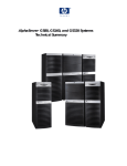
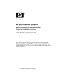
Figure 1–1 System Management Console
Corporate Network
GS320 with
8 Partitions
ConsoleWorks Screens
(one for each partition)
Terminal
Server
0 1 2 3
4 5 6 7
Private
LAN
System Management
Console PC
Modem
Partition
Partition
Partition
Partition
Partition
Partition
Partition
Partition
7
6
5
4
3
2
1
0
Modem
To Master SCM
COMPAQ
Modem
System
Initiated
Call
Remote Service PC
COMPAQ
PC on Corporate Network
PK-2702-00
1-2
SMC Installation and User's Guide
With the system management console (SMC), an AlphaServer GS80/160/320
system with multiple console lines can be managed from a single device. The
system management console consists of a DECserver 90M terminal server, a
Compaq Deskpro PC, and associated hardware and software. Figure 1–1 shows
a typical system.
The eight-port terminal server can connect to a maximum of eight partitions.
The console for each partition can be displayed in a terminal window under
ConsoleWorks.
The PC contains two network interfaces. The first connects to the terminal
server via a private LAN. The second connects to the corporate network,
enabling remote operation of the system management console through a Web
browser.
The PC also has an attached modem, which can provide Compaq Services
remote access to the GS80/160/320 system.
1
ConsoleWorks provides a sophisticated console management environment for
accessing the console of each partition, logging console line activity, and sending
notification of console or system events. In addition to local access through the
SMC, console lines can be accessed from any networked workstation by using a
Web browser.
NOTE: The PC that is supplied as part of the system management console is
supported by Compaq only with the hardware and software
configuration provided. To maintain this support, you may not add or
replace any components except as provided by Compaq.
1
The version of ConsoleWorks used on the SMC has been modified by the manufacturer,
TECSys Development Incorporated (TDI), to comply with the AlphaServer Management
Architecture. TDI’s standard version of ConsoleWorks cannot be used as a replacement
for this SMC application.
Overview
1-3
1.2
How to Use This Manual
The chapters and appendixes in this manual provide instructions for
installing and using the system management console and for restoring
the SMC disk.
Installing the system management console – In Part 2 of this manual,
Chapters 3 through 6 provide procedures for cabling and configuring the system
management console.
•
System with multiple consoles – If the system is partitioned, follow the
procedures in Chapters 3, 5 (except Section 5.7), and 6.
•
System with one console – Follow the procedures in Chapters 4, 5
(Sections 5.1 through 5.4 and 5.7 only), and 6.
Using the system management console – In Part 3, Chapters 7 through 10
provide information on using the system management console.
Troubleshooting – In Part 4, Chapter 11 provides basic troubleshooting
information.
In addition, five appendixes contain additional information about the system
management console.
1-4
SMC Installation and User's Guide
Part 2
Installing the
System Management Console
Chapter 2
Before You Begin
This chapter contains information you need before starting the installation.
Sections in this chapter are:
•
Installation Kit
•
Installation Sequence
Before You Begin
2-1
2.1
Installation Kit
The system management console consists of the SMC PC kit and the
terminal server kit. Typically the terminal server kit is installed at the
factory.
Table 2–1 SMC PC Kit
Part Number
Description
3X–DS8BA–xx
BOM for SMC PC kit; contains these items:
See note
Compaq Deskpro PC (minitower or desktop box)
including keyboard, mouse, and Windows NT 4.0 CD
3R–A1605–xx
Power cord and adapter for modem
3R–A1611–AA
Worldwide V.90/56K external serial modem (includes
PC-to-modem cable)
QB–6K4AA–SA
GS80/160/320 SMC software and documentation:
AG–RMDRB–BE, console management software
CD
AV–RMDQB–TE, SMC Installation and Release
Notes
QM–6K4AA–AA, license
EK–GSCON–IN, SMC Installation and User’s
Guide (this manual)
NOTE: The PC provided in this kit is the only one that works in this
configuration. See the 3X–DS8BA–xx BOM for the PC part number.
2-2
SMC Installation and User's Guide
The order number for the SMC PC kit is 3X–DS8BA–xx. It contains the
components listed in Table 2–1. (The monitor is separately ordered; it is not
part of the SMC PC kit.) The components of the SMC PC kit are installed at the
site.
When the SMC is ordered with the GS80/160/320 system, the terminal server
and cables are installed in the GS160/320 power cabinet or the GS80 cabinet at
the factory. When the SMC is not ordered with the GS80/160/320 system, the
terminal server kit is installed at the site. (Installation instructions are in
Appendix B for GS160/320 systems and Appendix C for GS80 systems.) The
order number for the terminal server kit is 3X–DS8AA–AA. Components of the
kit are listed in Table 2–2.
Table 2–2 3X–DS8AA–AA Terminal Server Kit
Quantity
Item
Description
1
DECserver 90M
Terminal server
4
BN25G–04
4-meter cable
4
BN25G–07
7-meter cable
1
BN24Q–07
7-meter crossover cable
8
H8585–AA
Connector
Mounting hardware
Before You Begin
2-3
2.2
Installation Sequence
Before installing the terminal server, check that the keyswitch and all
AC input box breakers on the GS80/160/320 system are turned to Off.
The following is the recommended sequence of installation for the GS80/160/320
system and the system management console:
1. Set up the GS80/160/320 hardware. See the AlphaServer GS80 Installation
Guide or the AlphaServer GS160/320 Installation Guide.
2. Set up the SMC PC and, with the GS80/160/320 keyswitch turned to Off,
turn on the breakers on the GS80/160/320 system cabinets and I/O cabinets
(Section 3.1 or Section 4.1).
3. Make the SMC cable connections (Sections 3.2 through 3.4 or Sections 4.2
and 4.3).
4. Configure the SMC software and verify communication from the system
management console to the system control manager (Chapter 5).
5. Optionally, configure the SMC for remote use (Chapter 6)
6. Power up the GS80/160/320 system (Chapter 6).
2-4
SMC Installation and User's Guide
Chapter 3
Connecting the SMC in a System with
Multiple Serial Console Lines
A system with multiple console lines is a GS80/160/320 system that has more
than one standard I/O (SIO) module. The SIO module is in a PCI box connected
to a quad building block, and on it is the SRM console firmware, which provides
a command-line interface for operator control of the system or a partition.
Sections in this chapter are:
•
Set Up the SMC
•
Cable the Terminal Server to the SMC
•
Cable the Terminal Server to the GS80/160/320
•
•
Make the Cable Connection
•
Record the Connections
•
Dress the Cables
Cable the SMC to the Corporate Network
Connecting the SMC in a System with Multiple Serial Console Lines
3-1
3.1
Set Up the SMC
Follow the instructions enclosed with the SMC system and monitor to
set them up, then start the system. With the GS80/160/320 keyswitch
turned off, turn on the AC input box breakers. Make cable connections.
Log on to the SMC system.
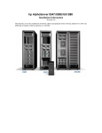
Figure 3–1 GS80/160/320 Keyswitch
3
PK-2737-00
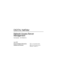
Figure 3–2 Windows NT Security Window
3-2
SMC Installation and User’s Guide
1. Set up the Compaq Deskpro computer and monitor according to the
accompanying instructions.
2. Start the SMC system. As the system software loads, enter information
when requested: user name, company name, product ID, and system name.
See the AlphaServer GS80/160/320 System Management Console
Installation and Release Notes for instructions.
3. Check that the keyswitch on the GS80/160/320 system is turned to Off ( in
Figure 3–1 points to the Off position) and then turn on the circuit breakers
on the AC input boxes. The breakers are accessible from the rear of both the
GS80 cabinet and the GS160/320 power cabinet. Then make the cable
connections described in Sections 3.2 through 3.4.
4. When the operating system software has finished loading, log on to the SMC
system using the administrator account. (The username is administrator;
for the password, press the Enter key.)
5. Optionally, change the password for the administrator account.
a. Press Ctrl+Alt+Del. The Windows NT Security window displays (Figure
3–2).
b. Click the Change Password… button. The Change Password dialog box
displays.
c.
Enter the old password and the new one, and confirm the new password.
Click OK.
6. Check the version of the SMC software by double-clicking the Version icon:
If the version is not 3.1, or if the desktop does not have a Version icon,
update the software. Refer to the AlphaServer GS80/160/320 System
Management Console Installation and Release Notes for instructions.
Connecting the SMC in a System with Multiple Serial Console Lines
3-3
3.2
Cable the Terminal Server to the SMC
Connect the management channel connector on the terminal server to
network adapter 2 on the SMC system.
Figure 3–3 Terminal Server Management Channel Connector
1
PK-1769-00
1. Connect one end of the BN24Q–07 cable (17–04308–05) to the management
channel connector on the terminal server ( in Figure 3–3).
2. Connect the other end of the cable to network adapter 2 on the SMC system
(Figure 3–4). The network adapters are numbered from left to right on the
minitower; bottom to top on the desktop.
NOTE: BN24Q is a crossover cable that can be used only for a point-to-point
Ethernet connection. It cannot connect an Ethernet node to a hub. If
such a connection is required, use a BN25G cable (17–03212–xx).
3-4
SMC Installation and User’s Guide
Figure 3–4 Network Adapter 2
Minitower
Model DPENCM
Minitower
Model DPENM
Desktop Box
Model DPENL
Desktop Box
Model DPEND
PK-1723-00
NOTE: The model type is on a label on the top or side of the SMC box.
Connecting the SMC in a System with Multiple Serial Console Lines
3-5
3.3
Cable the Terminal Server to the GS80/160/320
For PCI boxes in an expander cabinet, make the cable connection to
the terminal server. Then record the connections in the table provided
and dress the cables.
3.3.1
Make the Cable Connection
Cable the local port of the PCI box to the appropriate port on the
terminal server with a BN25G cable.
Figure 3–5 Local Port Location
1
PK-1724-00
The cable connections are made at the factory from the standard I/O modules in
PCI boxes in the GS160/320 power cabinet and in the GS80 cabinet. For PCI
boxes in expander cabinets, an H8585–AA connector (12–36054–01) is installed
on the local port ( in Figure 3–5) and a BN25G cable (17–03212–05) is labeled
and attached at the factory.
Make the connection to each console (PCI box with a standard I/O module) in an
expander cabinet. Follow the cabling chart in Table 3–1, and attach the BN25G
cable to the port on the terminal server ( in Figure 3–6).
Table 3–1 shows the suggested cabling for master PCI boxes only. This
numbering matches the default SMC setup. Secondary boxes (if there are any)
can be cabled to unused terminal server ports.
3-6
SMC Installation and User’s Guide
For information about partitioning the system, see AlphaServer GS80/160/320
Getting Started with Partitions.
Table 3–1 Terminal Server Cabling
QBB Number
Terminal Server
Port
GS80
GS160
GS320
1
0
0
0
2
1
1
1
3
—
2
2
4
—
3
3
5
—
—
4
6
—
—
5
7
—
—
6
8
—
—
7
Figure 3–6 Terminal Server Ports
1
PK-1770-00
Connecting the SMC in a System with Multiple Serial Console Lines
3-7
3.3.2
Record the Connections
Record the connections made for this installation in Table 3–2.
Table 3–2 Terminal Server Cabling at This Installation
Terminal Server Port
PCI Box Number
1
2
3
4
5
6
7
8
3-8
SMC Installation and User’s Guide
QBB Number
3.3.3
Dress the Cables
Form a service loop and tie wrap the BN25G cable to the rail.
Figure 3–7 Terminal Server Cable
2
3
1
2
3
4
5
6
7
8
1
PK-1753-00
1. At the PCI box end, tie wrap the BN25G cable (17–03212–05) to the CSB
junction cable (17–04936–xx) to form a service loop ( in Figure 3–7).
2. Tie wrap the BN25G cable down the rail of the expander cabinet (
).
3. At the bottom of the rail, coil the BN25G cable and place the extra length in
the rail ( ).
Connecting the SMC in a System with Multiple Serial Console Lines
3-9
3.4
Cable the SMC to the Corporate Network
Connect to the corporate network from network adapter 1 on the SMC
system.
Figure 3–8 Network Adapter 1
Minitower
Model DPENCM
Desktop Box
Model DPENL
Minitower
Model DPENM
Desktop Box
Model DPEND
PK-1727-00
NOTE: The model type is on a label on the top or side of the SMC box.
3-10
SMC Installation and User’s Guide
Connect a network cable to network adapter 1 on the SMC system, as shown in
Figure 3–8. (This cable is not included in the SMC installation kit.) The network
adapters are numbered from left to right on the minitower and from bottom to
top on the desktop.
Connecting the SMC in a System with Multiple Serial Console Lines
3-11
Chapter 4
Connecting the SMC in a System with
One Serial Console Line
A system with a single console line is a GS80/160/320 system that has only one
standard I/O (SIO) module. The SIO module is in a PCI box connected to a quad
building block, and on it is the SRM console firmware, which provides a
command-line interface for operator control of the system.
Sections in this chapter include:
•
Set Up the SMC
•
Cable the SMC to the GS80/160/320
•
Cable the SMC to the Corporate Network
•
Check the COM1
Connecting the SMC in a System with One Serial Console Line
4-1
4.1
Set Up the SMC
Follow the instructions enclosed with the SMC system and monitor to
set them up, then start the system. With the GS80/160/320 keyswitch
turned off, turn on the AC input box breakers. Make cable connections.
Log on to the SMC system.
Figure 4–1 GS80/160/320 Keyswitch
3
PK-2737-00
Figure 4–2 Windows NT Security Window
4-2
SMC Installation and User's Guide
1. Set up the Compaq Deskpro computer and monitor according to the
accompanying instructions.
2. Start the SMC system. As the system software loads, enter information
when requested: user name, company name, product ID, and system name.
See the AlphaServer GS80/160/320 System Management Console
Installation and Release Notes for instructions.
3. Check that the keyswitch on the GS80/160/320 system is turned to Off ( in
Figure 4–1 points to the Off position) and then turn on the breakers on the
AC input boxes. The breakers are accessible from the rear of both the GS80
cabinet and the GS160/320 power cabinet. Then make the cable connection
described in Section 4.2.
4. When the operating system software has finished loading, log on to the SMC
system using the administrator account. (For the password, press the Enter
key.)
5. Optionally, change the password for the administrator account.
a. Press Ctrl+Alt+Del. The Windows NT Security window displays (Figure
4–2).
b. Click the Change Password… button. The Change Password dialog box
displays.
c.
Enter the old password and the new one, and confirm the new password.
Click OK.
6. Check the version of the SMC software by double-clicking the Version icon:
If the version is not 3.1, or if the desktop does not have a Version icon,
update the software. Refer to the AlphaServer GS80/160/320 System
Management Console Installation and Release Notes for instructions.
Connecting the SMC in a System with One Serial Console Line
4-3
4.2
Cable the SMC to the GS80/160/320
Connect the COM1 port of the SMC system to the local port of the
GS80/160/320.
Figure 4–3 COM1 Port
Minitower
Model DPENCM
Desktop Box
Model DPENL
COM1 (A)
COM1 (A)
Minitower
Model DPENM
Desktop Box
Model DPEND
COM1 (A)
COM1 (A)
PK-1735-00
NOTE: The model type is on a label on the top or side of the SMC box.
4-4
SMC Installation and User's Guide
Install H8585–AA connectors (12–36054–01) on the COM1 (or A) port of the
SMC system (Figure 4–3) and the local port of the standard I/O module in the
GS80/160/320 system primary PCI box ( in Figure 4–4). Connect these ports
with a BN24Q cable (17–04308–05).
Figure 4–4 Local Port Connection
1
PK-1724-00
Connecting the SMC in a System with One Serial Console Line
4-5
4.3
Cable the SMC to the Corporate Network
Connect to the corporate network from the network adapter on the
SMC system.
Figure 4–5 Network Adapter 1
Minitower
Model DPENCM
Desktop Box
Model DPENL
Minitower
Model DPENM
Desktop Box
Model DPEND
PK-1727-00
NOTE: The model type is on a label on the top or side of the SMC box.
4-6
SMC Installation and User's Guide
Connect a network cable to network adapter 1 on the SMC system, as shown in
Figure 4–5. (This cable is not included in the SMC installation kit.) The network
adapters are numbered from left to right on the minitower and from bottom to
top on the desktop.
Connecting the SMC in a System with One Serial Console Line
4-7
4.4
Check the COM1 Settings
Check that the baud rate for the COM1 port is 9600. Change it if it is set
to any other speed. Check the other COM1 settings.
Figure 4–6 Ports Dialog Box
4-8
SMC Installation and User's Guide
1. From the Start button select Settings|Control Panel.
2. In the control panel, double-click the Ports icon. The Ports dialog box
displays (Figure 4–6).
3. Select COM1 and click the Settings… button. The Settings for COM1 dialog
box displays (Figure 4–7).
4. If the baud rate displayed is not 9600, change it to 9600. Set the Data Bits
to 8, Parity to None, Stop Bits to 1, and Flow Control to XON/XOFF. If these
settings are not compatible with your environment, change them to settings
that are.
Figure 4–7 Settings for COM1 Dialog Box
Connecting the SMC in a System with One Serial Console Line
4-9
Chapter 5
Configuring the SMC Software
The software to be configured depends on the number of consoles in the system.
These sections apply to all systems:
•
Set the SMC System Time, Date, and Time Zone
•
Configure the Network Connections
•
Enter the Mail Server Name in the ConsoleWorks Script
•
Configure Outlook Express
•
Delete Unused Consoles in ConsoleWorks
These sections apply only to systems that have multiple consoles:
•
Configure the Terminal Server: Access Server Loader
•
Configure the Terminal Server: Access Server Manager
This section applies only to systems that have a single console:
•
Replace the ConsoleWorks Configuration File
NOTE: The GS80/160/320 system should not be powered on at this point. If it
is, power it down by turning the keyswitch on the operator control panel
to Off and turning off the breakers on the AC input boxes.
Configuring the SMC Software
5-1
5.1
Set the SMC System Time, Date, and Time Zone
Use the Date/Time icon in the Control Panel to set the time, date, and
time zone.
Figure 5–1 Date & Time Tab
5-2
SMC Installation and User’s Guide
1. From the Start button select Settings|Control Panel. The Control Panel
window displays.
2. In the Control Panel double-click the Date/Time icon. The Date/Time
Properties dialog box displays.
3. In the Date & Time tab, set the date and time (Figure 5–1).
4. Select the Time Zone tab (Figure 5–2).
5. From the drop-down menu select the time zone for this installation. Click
OK.
Figure 5–2 Time Zone Tab
Configuring the SMC Software
5-3
5.2
Configure the Network Connections
Verify the computer name and the protocol for the private LAN.
Specify the IP address. Finally, set up the adapter for the corporate
network.
5.2.1
Verify the Computer Name
Figure 5–3 Identification Changes Dialog Box
5-4
SMC Installation and User’s Guide
1. Open the Windows Control Panel: From the Start menu select
Settings|Control Panel.
2. Double-click the Network icon. The Network dialog box displays with the
Identification tab selected.
3. Click the Change… button. The Identification Changes dialog box displays
(Figure 5–3). Check that the box labeled Computer Name correctly identifies
the SMC system as a management station on the corporate network. (In the
example shown in Figure 5–3, that name is MySMC.) If it does not, enter
the correct name. Click OK.
4. The system can be a member of a workgroup or a domain. (If you are unsure
which it should be, ask the network administrator.) Select the appropriate
option button and enter the workgroup or domain name.
NOTE: The computer name entered in step 3 cannot be GSSMC1. This name is
reserved for the terminal server.
Configuring the SMC Software
5-5
5.2.2
Verify the Network Protocol
Figure 5–4 Network Dialog Box
5-6
SMC Installation and User’s Guide
1. In the Network dialog box, select the Protocols tab (Figure 5–4). If the
protocol shown is TCP/IP, skip the rest of this page and go on to Section
5.2.3.
2. If the protocol shown is not TCP/IP, highlight the protocol and click the
Remove button. A message box displays; click Yes.
3. In the Network dialog box, click the Add… button. The Select Network
Protocol dialog box displays (Figure 5–5). Highlight TCP/IP Protocol. Click
OK. A box displays with a message that begins “If there is a DHCP server
on your network….” Click No.
4. The Windows NT Setup dialog box displays. Click Continue.
Figure 5–5 Select Network Protocol Dialog Box
Configuring the SMC Software
5-7
5.2.3
Configure Network Adapter 1
Figure 5–6 Microsoft TCP/IP Properties
NOTE: The IP address values in the illustration are an example only. Obtain
the correct values for this installation from the network administrator.
5-8
SMC Installation and User’s Guide
Enter the static IP address, subnet mask, and gateway. Ask the network
administrator for this information. The SMC requires a static IP address; it
cannot have a dynamic address (that is, an address assigned by a DHCP
server).
1. In the Adapter box of the Microsoft TCP/IP Properties dialog box (Figure 5–
6), select adapter 1.
2. Select the option button labeled Specify an IP address. Enter the IP address,
subnet mask, and gateway. Click OK.
NOTE: The network card shown in Figure 5–6 is an example only. Another type
of network card might be supplied.
Configuring the SMC Software
5-9
5.2.4
Configure Network Adapter 2
Figure 5–7 Microsoft TCP/IP Properties Dialog Box
5-10
SMC Installation and User’s Guide
1. In the Network dialog box, select the Protocols tab. Click the Properties
button.
2. The Microsoft TCP/IP Properties dialog box displays (Figure 5–7). Select
adapter 2.
3. Select the option button labeled Specify an IP address. Enter the following
information:
IP address:
Subnet mask:
90.0.0.100
255.255.255.0
Leave the Default Gateway blank. Click OK.
NOTE: The network card shown in Figure 5–7 is an example only. Another type
of network card might be used.
Configuring the SMC Software
5-11
5.2.5
Bind the Protocol
Figure 5–8 Bindings Tab in the Network Dialog Box
1. In the Network dialog box, select the Bindings tab. A box with a progress
bar displays.
2. When the progress bar indicates that the operation is finished, click Close.
3. Restart the SMC system.
5-12
SMC Installation and User’s Guide
5.2.6
Verify the Network Setup
Figure 5–9 Verifying the Network Setup
1. Open a Command window: From the Start menu select Programs|
Command Prompt.
2. At the prompt type ping 90.0.0.100. The response should look similar to
the first command in Figure 5–9.
3. At the prompt type ping name, where name is the fully qualified computer
name displayed in Section 5.2.1. The response should look similar to the
second command in Figure 5–9.
Configuring the SMC Software
5-13
5.3
Enter the Mail Server Name in the ConsoleWorks
Script
Modify the file MAIL.PL to include the name of the mail server. This
file is in the folder C:\Cwks\Actions\Event.
Example 5–1 Modifying the ConsoleWorks Script (MAIL.PL)
#!/usr/local/bin/perl
# Note: This is written in a very simple version of Perl for
# non-experts)
# In perl, a single character match is the period ".",
# contrasting with "%" in ConsoleWorks.
# Multi is "*" in both cases.
# Also for WinNT, you can not start a perl file directly,
# though you can in a command window
# Therefore create a single line script MAIL.BAT like this
# C:\Perl\Bin\Perl C:\Cwks\Actions\Event\mail.pl %1 %2 %3 %4
# %5 %6
#+
# Before this can be used, please change the $remote = line in
# the smtpmail subroutine
#
# Mail Action Script
#
# $ARGV[0] Console name
# $ARGV[1] Event Name
# $ARGV[2] Event Sequence Number
# $ARGV[3] Name of event context file
# $ARGV[4] Contact name(s), comma delimited
# $ARGV[5] User Supplied Paramter
#use Socket;
sub smtpmail {
my ($to, $subj, $whoami, $mf, @msg) = @_;
my ($port, $iaddr, $paddr, $proto, $line);
# This is site specific
$remote = "my.email.server.name.net";
.
.
.
if ($domail) {
5-14
SMC Installation and User’s Guide
Modify the file MAIL.PL to include the name of the mail server. This file is in
the folder C:\Cwks\Actions\Event.
1. Open MAIL.PL in Notepad or another text editor.
2. Find the line ‘$remote = “my.email.server.name.net”;’ ( in Example 5–1.
The example shows an excerpt from the file; for a full listing of MAIL.PL,
see Appendix D.)
3. Obtain the name of the mail server from the network administrator.
Replace everything between the double quotes with the server name.
4. Save the file and close the editor.
Configuring the SMC Software
5-15
5.4
Configure Outlook Express
Obtain mail server information from the network administrator before
configuring.
Figure 5–10 Internet Accounts Dialog Box
1. Double-click the Outlook Express icon on the desktop. If this is the first time
Outlook Express is opened, a box displays asking where messages should be
stored. Select a folder and click OK. The Outlook Express window displays.
2. From the Tools menu select Accounts. The Internet Accounts dialog box
displays (Figure 5–10).
3. Select the Mail tab and click the Add button. In the fly-out menu select
Mail…. The Internet Connection Wizard displays.
4. The wizard asks for the following information; obtain it from the network
administrator:
a. The address of the e-mail account that will send and receive mail on the
SMC.
5-16
SMC Installation and User’s Guide
b. The type of server for incoming mail. Outlook Express recognizes POP3
and IMAP.
c.
The names of the incoming and outgoing mail servers.
5. When Outlook Express sends or receives mail, by default it removes the
messages from the server. To leave a copy of messages on the server, do the
following:
a. From the Tools menu select Accounts. In the Internet Accounts window
right-click on the account name and select Properties from the pop-up
menu. The account_name Properties dialog box displays (Figure 5–11).
b. Select the Advanced tab. In the section labeled Delivery select the
checkbox labeled Leave a copy of messages on server.
Figure 5–11
account_name Properties Dialog Box
Configuring the SMC Software
5-17
5.5
Delete Unused Consoles in ConsoleWorks
Start and log on to ConsoleWorks. Select Consoles and Delete Console.
Figure 5–12 ConsoleWorks Delete Console Screen
5-18
SMC Installation and User’s Guide
The default configuration for ConsoleWorks is eight consoles. If the
GS80/160/320 system has fewer than eight consoles (that is, fewer than eight
PCI boxes with standard I/O modules that are connected to the terminal server),
delete the extras in ConsoleWorks.
NOTE: Unused consoles generate a great number of events, causing the log files
and the file DEFAULT.CONFIG to grow to an unmanageable size and
slow down the system. Deleting unused consoles is strongly
recommended.
1. Start and log on to ConsoleWorks (Section 8.1).
2. In the left navigation panel of the ConsoleWorks window select Consoles.
The Show Consoles screen displays.
3. At the top of the Show Consoles screen select Delete Console. The Delete
Console screen displays (Figure 5–12).
4. From the Delete dropdown menu select the console to be deleted.
5. Click the Delete Console button. A verification message displays (Figure 5–
13).
6. Click OK to delete the console. The Show Consoles screen displays; the
deleted console is no longer listed.
Figure 5–13 Delete Console Verification Message
Configuring the SMC Software
5-19
5.6
Configure the Terminal Server: Access Server
Loader
Access Server Loader configures the IP address and subnet mask of the
terminal server.
5.6.1
Open Access Server Loader
Figure 5–14 Access Server Loader Window
5-20
SMC Installation and User’s Guide
1. Start Access Server Loader: From the Start menu select Programs|Access
Server Loader|Access Server Loader. The Access Server Loader window
displays (Figure 5–14).
2. Click Setup. The Confirm dialog box displays (Figure 5–15). Click Yes.
Figure 5–15 Access Server Loader Confirm Dialog Box
Configuring the SMC Software
5-21
5.6.2
Create the Database
Figure 5–16 Access Server Loader Configuration Dialog Box
5-22
SMC Installation and User’s Guide
1. The Access Server Loader Configuration dialog box displays (Figure 5–16).
On the Clients tab, enter the following information:
Host Name: computer name (Section 5.2.1)
Hardware Addr: from the label on the terminal server (
IP Addr: 90.0.0.1
Subnet Mask: 255.255.255.0
in Figure 5–17)
NOTE: The IP address you enter in the Access Server Loader Configuration
dialog box is the IP address for the terminal server, not for the host.
2. Click OK. The Access Server Loader window displays.
Figure 5–17 Location of Hardware Address Label
00
-6
0-
6D
-9
3-
57
-C
0
1
PK-1783-00
Configuring the SMC Software
5-23
5.6.3
Verify the Connection
Figure 5–18 Access Server Loader Window
Figure 5–19 Verifying the Connection
5-24
SMC Installation and User’s Guide
1. Keeping the GS80/160/320 keyswitch in the Off position, turn on the
breakers on the AC input boxes.
NOTE: Turning on the breakers applies power to the terminal server. These
instructions assume that the terminal server has not been powered
on until now. If it was on when you reached this point, power cycle
the terminal server now.
2. Check the Access Server Loader window (Figure 5–18) for the following:
a. The indicators on the BOOTP Server On/Off button and the TFTP
Server On/Off button should display green. If an indicator displays red,
click the button.
b. The hardware address after Reply in the BOOTP Server block should
match the hardware address label on the terminal server. If it has been
at least one minute since you turned on the AC input box breakers and
the addresses do not match, do the following:
1. Check that the terminal server has power (Section B.4 or C.4).
2. Check that the cable from the terminal server to the SMC system is
connected correctly (Section 3.4).
3. Check that the position identifier dial on the terminal server is set
correctly (Section B.3 or C.3).
If, after performing these three checks, you find that the Request
address is still different from the hardware address on the terminal
server label, refer to the terminal server documentation.
3. Click the Close button to close Access Server Loader.
4. Verify the connection.
a. Open a Command window: From the Start menu select
Programs|Command Prompt.
b. At the prompt, type ping 90.0.0.1. The response should be similar to
Figure 5–19.
c.
Close the Command window.
Configuring the SMC Software
5-25
5.7
Configure the Terminal Server: Access Server
Manager
Access Server Manager configures the terminal server for access by the
SMC system.
5.7.1
Open Access Server Manager
Figure 5–20 New Access Server Window
5-26
SMC Installation and User’s Guide
1. Start Access Server Manager. From the Start menu select Programs|
Access Server Manager|Access Server Manager. The Access Server
Manager window displays.
2. From the File menu select New. The New Access Server dialog box displays
(Figure 5–20). The default Login Password is access and the default
Privileged Password is system. Click OK.
3. The Access Server dialog box displays (Figure 5–21).
Figure 5–21 Access Server Dialog Box
Configuring the SMC Software
5-27
5.7.2
Test the Connection
Figure 5–22 Access Server Dialog Box, Utilities Tab
5-28
SMC Installation and User’s Guide
1. In the Access Server dialog box, select the Utilities tab (Figure 5–22). Select
Test Connection. Click the Do It Now… button. The message “Access Server
connection test successful” displays. Click OK.
2. Select Connect to Telnet Console. Click the Do It Now… button. The Telnet
window displays (Figure 5–23).
3. At the Local> prompt type show server. A snapshot of the server displays.
This confirms the connection.
4. Close the Telnet window.
Figure 5–23 Telnet Window
Configuring the SMC Software
5-29
5.7.3
Configure Access Server Manager
Figure 5–24 Select a Command File Dialog Box
5-30
SMC Installation and User’s Guide
1. From the Utilities tab of the Access Server dialog box (Figure 5–22), select
Run Command File.
2. Click the Do It Now… button. The Select a Command File dialog box
displays (Figure 5–24).
3. Select the file GS_CON.cmds. Click Open. The Run Command File dialog
box displays (Figure 5–25). Click OK. The command file runs.
4. Close the Access Server dialog box and return to Access Server Manager.
5. Close Access Server Manager.
Figure 5–25 Run Command File Dialog Box
Configuring the SMC Software
5-31
5.8
Replace the ConsoleWorks Configuration File
The default configuration file put in place by the SMC installation
process is for multiple-console systems. If this system has only one
console, replace the configuration file.
Figure 5–26 Configuration Files Folder
5-32
SMC Installation and User’s Guide
1. In Windows Explorer go to the folder C:\Cwks\Config (Figure 5–26).
2. Copy the file SERIAL_COM1_DEFAULT.CONFIG:
a. Click on the file to highlight it.
b. From the Edit menu select Copy.
3. From the Edit menu select Paste. A file named Copy of
SERIAL_COM1_DEFAULT.CONFIG is pasted into the folder.
4. Delete the file DEFAULT.CONFIG.
5. Rename the file Copy of SERIAL_COM1_DEFAULT.CONFIG to
DEFAULT.CONFIG:
a. Click on the file to highlight it.
b. From the File menu select Rename.
c.
In the highlighted name enter DEFAULT.CONFIG.
Configuring the SMC Software
5-33
Chapter 6
Configuring the SMC for Remote Use
Sections in this chapter are:
•
Set Up the Modem
•
Configure the Remote Access Software
NOTE: When you have finished setting up the modem and configuring the
remote access software, restart the SMC system and set the keyswitch on
the GS80/160/320 to On.
Configuring the SMC for Remote Use
6-1
6.1
Set Up the Modem
Follow the manufacturer’s instructions for cabling the modem.
Figure 6–1 COM2 Port
Minitower
Model DPENCM
Desktop Box
Model DPENL
COM2 (B)
COM2 (B)
Minitower
Model DPENM
Desktop Box
Model DPEND
COM2 (B)
COM2 (B)
PK-1735A-00
NOTE: The model type is on a label on the top or side of the SMC box.
1. Cable the modem, following the manufacturer’s instructions. Connect the
RS-232C cable from the SMC installation kit to COM2 on the SMC system
(Figure 6–1; COM2 might be marked B).
6-2
SMC Installation and User's Guide
2. Open the Control Panel: From the Start menu select Settings|Control
Panel.
3. Double-click the Modems icon. The Install New Modem dialog box displays.
Click Next. The operating system detects the modem and tests it.
4. The Install New Modem dialog box displays, with the words Standard
Modem in the box. Click the Change… button. Click the Have Disk…
button. Insert the disk that came with the modem in the appropriate drive.
5. In the dialog box click the Browse button, and select the drive and file.
Select the modem type.
6. Check that the Modem Properties box (Figure 6–2) displays, indicating that
the modem has installed correctly.
Figure 6–2 Modem Detected
Configuring the SMC for Remote Use
6-3
6.2
Configure the Remote Access Software
Configure both remote access applications, Carbon Copy Access
Edition and WinVNC.
6.2.1
Carbon Copy Access Edition
Figure 6–3 Communication Properties Dialog Box
6-4
SMC Installation and User's Guide
1. Start Carbon Copy Access Edition: From the Start menu select
Programs|Carbon Copy Access Edition|Carbon Copy.
2. From the Options menu select Communications. The Communication
Properties dialog box displays (Figure 6–3).
NOTE: Check with the customer before setting up the Wait for Call feature.
3. In the tab labeled Wait for Call, select the modem and the corporate
network in the box labeled Select the connection types. In the Options block,
select Wait for Call on Startup. Click OK.
4. In the Carbon Copy Access Edition window (Figure 6–4), click the Wait for
Call button. If you selected Minimize on Wait for Call in the Communication
Properties dialog box, the program now minimizes.
Figure 6–4 Carbon Copy Access Edition Window
Configuring the SMC for Remote Use
6-5
6.2.2
WinVNC
Figure 6–5 Default Local System Properties Dialog Box
1. Display the WinVNC settings: from the Start menu select Programs|
VNC|Administrative Tools|Show Default Settings. The Default Local
System Properties dialog box displays (Figure 6–5).
2. Enter a password and select the checkboxes shown in Figure 6–5.
6-6
SMC Installation and User's Guide
Part 3
Using the
System Management Console
Chapter 7
Getting Started with the
System Management Console
Sections in this chapter are:
•
Logging on to the SMC
•
Using the SMC Locally
•
Using the SMC Remotely
•
Keep in Mind
Getting Started with the System Management Console
7-1
7.1
Logging on to the SMC
Logon is automatic if the administrator account has no password. For
manual logon, a different account can be used, or the administrator
account can be given a password.
Figure 7–1 Windows NT Security Window
The SMC system is configured to log on to the administrator account
automatically when it powers up. If you leave the administrator account with
the default configuration (that is, without a password), you can log on to
another account by following these instructions.
1. Close all applications.
2. Press Ctrl+Alt+Del. The Windows NT Security window displays (Figure 7–
1).
3. Click Logoff… . A window displays with the message “This will end your
Windows NT session.”
4. Click OK and immediately depress and hold the Shift key. Hold this key
until the Log On dialog box displays.
5. Enter a username and password that are valid for this system. Click OK.
7-2
SMC Installation and User's Guide
If the administrator account is reconfigured to use a password, the Log On
dialog box always displays when the PC powers up. You can give that account a
password by following these instructions.
1. Press Ctrl+Alt+Del. The Windows NT Security window displays (Figure 7–
1).
2. Click Change Password… The Change Password dialog box displays (Figure
7–2).
3. Enter the old password and the new one, and enter the new password again
to confirm it. (The passwords display as asterisks.) Click OK.
Figure 7–2 Change Password Dialog Box
Getting Started with the System Management Console
7-3
7.2
Using the SMC Locally
Icons on the SMC desktop are used to run applications locally.
Figure 7–3 SMC Desktop
The SMC desktop has several icons that enable you to run applications and
view documentation online. Table 7–1 shows the icons and describes the result
of double-clicking each.
7-4
SMC Installation and User's Guide
Table 7–1 SMC Desktop Icons
Icon
Function
Runs ConsoleWorks, the console management application used
by the SMC. See Chapter 8 for a quick reference and the
ConsoleWorks Administration/User Guide for more in-depth
information.
NOTE: Since ConsoleWorks runs in the Internet Explorer
browser, the first time you start it, the Internet Explorer
Setup Wizard runs. You will need to supply connection
information, including proxies if applicable.
Runs Compaq AlphaServer Partition Manager (CAPM), an
application that simplifies the creation of partitions on the
GS80/160/320 system. Chapter 9 describes this application.
Displays a PDF file of the AlphaServer GS80/160/320 System
Management Console Installation and User’s Guide (this
manual). PDF files are viewed online and can be printed.
Displays a PDF file of the ConsoleWorks Administration/ User
Guide.
Displays version information for the SMC release and all
software distributed on the SMC software CD.
Opens the SMC Web page (see Section 7.3).
Getting Started with the System Management Console
7-5
7.3
Using the SMC Remotely
The SMC Web page is used to run applications remotely.
Figure 7–4 SMC Web Page
7-6
SMC Installation and User's Guide
To display the SMC Web page from a system that is networked to the SMC
system and running Windows, open a Web browser and enter the address
http://name.domain:2301/smc/smc.htm, where name.domain is the fully
qualified address or the IP address of the SMC system on the corporate
network; press Enter. The supported browsers are Internet Explorer V5.0 or
later and Netscape V4.7 or later.1 Browsers must have Java and JavaScript
enabled.
To display the SMC Web page on a system with a browser that does not work
with JavaScript, DOM and DHTML, enter this in the Address box:
http://name.domain:2301/smc/smca.htm. Before viewing it the first time,
edit SMCA.HTM to change all occurrences of “localhost” to the fully qualified
address or the IP address of the SMC system.
You can run these applications and view these documents from the SMC Web
page:
ConsoleWorks – ConsoleWorks is the console management application used by
the SMC. See Chapter 8 for a quick reference and the ConsoleWorks
Administration/User Guide for more in-depth information.
Compaq AlphaServer Partition Manager (CAPM) – CAPM simplifies the
creation of partitions on the GS80/160/320 system. Chapter 9 has instructions
for using this application. CAPM requires that JRE 1.3.0_01 or later be
installed on the system from which it is run.
Compaq Insight Manager (CIM) – Insight Manager is a system management
product that monitors the operations of Compaq servers, workstations,
desktops, and portables.
SMC User’s Guide – This link is to a PDF file of the AlphaServer
GS80/160/320 System Management Console Installation and User’s Guide (this
manual). PDF files are viewed online and can be printed. Acrobat Reader 4.05c
or later is required.
ConsoleWorks User’s Guide – This is a link to the PDF file for the
ConsoleWorks Administration/User Guide.
You can also check the software version of all SMC applications from the SMC
Web page. To do this, click the Version Details link at the upper right of the
page.
1
Netscape V6.0 running on Windows 98 is not supported.
Getting Started with the System Management Console
7-7
7.4
Keep in Mind
Keep these points in mind when you use the system management
console.
•
An SMC may be used with only one GS80/160/320 system. Do not attach it
to multiple systems or other equipment.
•
The GS80/160/320 SCM and SRM may not have associated passwords.
•
The SCM escape sequence must be the default, <Esc><Esc>scm.
•
The SMC requires a static IP address.
•
In the SMC Web page, use the IP address or the fully qualified system name
for the SMC system. Do not use localhost.
•
In order for CAPM to run, ConsoleWorks services must be running, but the
ConsoleWorks application must be closed. In addition, the CAPM service
must be running. If CAPM is run from the SMC Web page, the SMC HMMO
service must also be running.
7-8
SMC Installation and User's Guide
Chapter 8
ConsoleWorks
ConsoleWorks is a Web-based application that monitors and logs output from
the GS80/160/320 consoles.
This chapter provides a quick reference for the procedures most commonly
performed on a GS80/160/320 system management console (SMC). For more
information about ConsoleWorks, see the ConsoleWorks Administration/User
Guide. (You can open this manual from the desktop icon on the SMC system or
from the link on the SMC Web page.)
Sections in this chapter are:
•
•
Starting ConsoleWorks
•
Overview of ConsoleWorks
•
Adding a User
•
ConsoleWorks Screen
•
•
Managing Consoles
Communicating with Another
User
•
Changing a User Password
•
Adding a Profile
•
Modifying a Profile
•
•
Loading Certificate Authority
•
Deleting a Console
•
Adding a Console
•
Renaming a Console
•
Managing Events and Actions
Managing Users
Managing ConsoleWorks Log Files
•
Viewing a Log File
•
Deleting Log Files
•
Mailing a Log File
•
Adding an Event
•
Importing and Using CompaqSupplied Events
•
Saving the Configuration
•
Enabling an Action
•
Using KEA! with ConsoleWorks
•
Adding a Scan
•
Acknowledging and Purging
Events
Expunging Events
•
ConsoleWorks
8-1
8.1
Starting ConsoleWorks
Start ConsoleWorks from the desktop icon or from the SMC Web page.
Figure 8–1 SMC Web Page
8-2
SMC Installation and User’s Guide
You can run ConsoleWorks from the SMC system or from a workstation
networked to the SMC system.
•
To run ConsoleWorks from the SMC system, double-click the ConsoleWorks
desktop icon:
•
To run ConsoleWorks from a workstation networked to the SMC system,
click the icon on the SMC Web page (Figure 8–1). To display the SMC Web
page on a system running Windows, enter this in the browser Address box:
http://name.domain:2301/smc/smc.htm, where name.domain is the
fully qualified address or the IP address of the SMC on the corporate
network; press Enter. To display the SMC Web page on a system with a
browser that does not work with JavaScript, DOM and DHTML, enter this
in the Address box: http://name.domain:2301/smc/smca.htm.
Logging on to ConsoleWorks
When you start ConsoleWorks, a logon screen displays. The first time you log
on, use these defaults:
Username: console_manager
Password: setup
Section 8.6.1 has instructions for creating other user accounts.
ConsoleWorks
8-3
8.2
Overview of ConsoleWorks
ConsoleWorks is a Web-based application that monitors console output
and provides console management functions. Compaq provides a script
that customizes ConsoleWorks for the system management console and
GS80/160/320 environment.
Figure 8–2 ConsoleWorks Application and Script
C:\Cwks\import_pcm
SCM.port
3
1
2
To Mail Server
Console Works
Event Detection
SMTP Mail
Notification
GS80/160/320
5
Action
Generation
Perl
Serial Ports
Console Lines
RUN "Prog"/Fixed
Parameters
Mail.BAT
Mail.PL
Mail.PL
4
ConsoleWorks SubDirectory
[C:\Cwks\Actions\Event]
Scripting Engine
PK-2703-00
ConsoleWorks is a Web-based application that manages consoles in a
GS80/160/320 system. A console can be a partition or the entire system if it is
not partitioned. The SMC system administrator determines the consoles to
which a user has access and the level of that access. The level of access is
indicated by a profile; each user is associated with one or more profiles.
ConsoleWorks provides access to each console directly from the SMC. In
addition, KEA! can be used with ConsoleWorks to display console activity.
Alternatively, you can use a supported Web browser to access each console
remotely from a workstation connected to the private LAN or to the corporate
network. The output from each console is logged to a file for future viewing.
8-4
SMC Installation and User’s Guide
ConsoleWorks monitors console output for events, text strings in a console’s
SCM or SRM output. Each event is part of one or more scans, or collection of
events. A scan, in turn, is associated with one or more consoles.
Compaq has customized the ConsoleWorks application used in the SMC to
monitor for particular events and to send mail to user-specified recipients when
those events occur. The diagram in Figure 8–2 shows the actions that take place
when ConsoleWorks recognizes an alert; callouts are described here:
The GS80/160/320 system generates a console alert. (This does not include
operating system alerts.)
As with all console activity, the alert travels through the GS80/160/320
serial port and over the console line to the SMC.
ConsoleWorks monitors all activity on the console line. It detects an event
based on information in the file SCM.PORT and generates an action.
The action taken by ConsoleWorks is to run the file MAIL.BAT, which in
turn runs MAIL.PL.
The scripting agent interprets MAIL.PL and sends SMTP mail to the mail
server, which delivers it to the specified recipient. Figure 8–3 shows a
representative mail message.
Figure 8–3 Mail Message from ConsoleWorks
ConsoleWorks
8-5
8.3
ConsoleWorks Screen
The ConsoleWorks screen is divided into three sections: left navigation
panel, main data panel, and lower navigation panel.
Figure 8–4 ConsoleWorks Screen
8-6
SMC Installation and User’s Guide
Figure 8–4 shows the first screen that displays after you log in to
ConsoleWorks. The three parts of the screen are described below.
Left navigation panel – This panel is divided into three segments (from
top to bottom):
•
Function links (Consoles, Groups, Send Message, and Logout). Clicking
any of these results in either the display of new information in the
main data panel or the display of a new popup window.
•
Menu links (Admin, Manage, Change, Reports, Download, and Help).
Clicking any of these links causes the display in the lower third of the
left navigation panel to change to the related selection links.
•
Selection links. This list changes depending on which menu link is
chosen. Clicking on most of these links causes the display of new
information in the main data panel, but a few result in the display of a
new popup window.
Main data panel – Most configuration information and data display in
this panel.
Lower navigation panel – On the left are links, status, and the mailbox
icon; on the right is the ConsoleWorks status display table.
ConsoleWorks
8-7
8.4
Managing Consoles
ConsoleWorks provides access to each console line in a GS80/160/320
system directly from the SMC.
Figure 8–5 Show Consoles Screen
8-8
SMC Installation and User’s Guide
ConsoleWorks is used to manage the console lines in a GS80/160/320 system.
To find information about a console line, start by clicking the Consoles link in
the left navigation panel of any ConsoleWorks screen to display the Show
Consoles screen (Figure 8–5). From there you can view a console line’s activity
or its configuration, delete a console (Section 8.4.2) or add one (Section 8.4.3).
NOTE: When you open a console, a security warning displays. By loading the
certificate authority (Section 8.4.1), you can limit this warning to once.
Viewing a Console’s Activity
Click the monitor icon on the Show Consoles screen (to the left of the console
name) to display the terminal emulator window for the console. The monitor
icon looks like this:
Viewing a Console’s Configuration
Click the console name link on the Show Consoles screen to display the
console_name Configuration screen.
ConsoleWorks
8-9
8.4.1
Loading Certificate Authority
The Java applet used in ConsoleWorks warns of a potential security
violation on the SMC PC. By loading the certificate authority, which is
on the C drive with the application, you agree that content from
TECSys Development, Inc. can be trusted.
Privileges required: Admin – none; Console – none
Figure 8–6 Security Warning
8-10
SMC Installation and User’s Guide
When you open a console, a security warning displays (Figure 8–6). To prevent
repeated display of this warning, load the TDI security certificate.
1. In the left navigation panel of any ConsoleWorks screen, select Download.
2. From the selection links at the bottom of the left navigation panel, select
TDI Certificate. The File Download dialog box displays (Figure 8–7).
3. Select the option button labeled Open this file from its current location and
click OK.
Continued on page 8-13
Figure 8–7 File Download Dialog Box
ConsoleWorks
8-11
Figure 8–8 TDI Certificate
8-12
SMC Installation and User’s Guide
4. The certificate displays (Figure 8–8). Click Install Certificate….
5. The Certificate Manager Import Wizard displays. Follow the instructions in
the wizard and accept the defaults. At the end click Finish.
6. The Root Certificate Store window displays (Figure 8–9). Click Yes.
7. The certificate displays again. Click OK.
Figure 8–9 Root Certificate Store Window
ConsoleWorks
8-13
8.4.2
Deleting a Console
Select Consoles in the left navigation panel, then Delete Console at the
top of the screen.
Privileges required: Admin – R W C; Console – none
Figure 8–10 Delete Console Screen
8-14
SMC Installation and User’s Guide
NOTE: Be sure you want to delete the console, since you cannot undo this
operation. If you accidentally delete a console, use the Add Console
function (Section 8.4.3) to reconfigure it.
1. In the left navigation panel select Consoles. The Show Consoles screen
displays.
2. At the top of the Show Consoles screen select Delete Console. The Delete
Console screen displays (Figure 8–10).
3. From the Delete dropdown menu select the console to be deleted.
4. Determine if the log files for the console will be deleted. To delete them,
select the checkbox labeled Delete logfiles also.
5. Click the Delete Console button. A verification message displays (Figure 8–
11).
6. Click OK to delete the console. The Show Consoles screen displays; the
deleted console is no longer listed.
Figure 8–11 Delete Console Verification Message
ConsoleWorks
8-15
8.4.3
Adding a Console
Select Consoles in the left navigation panel, then Add Console at the
top of the screen. The type is Telnet. Do not attempt to add a console if
eight consoles already exist.
Privileges required: Admin – R W C; Console – none
Figure 8–12 Add Telnet Console Screen
8-16
SMC Installation and User’s Guide
1. In the left navigation panel select Consoles. The Show Consoles screen
displays.
NOTE: The maximum number of consoles supported by this version of
ConsoleWorks is eight. If the Show Consoles screen lists eight
consoles (not including the ConsoleWorks internal console,
CONWRKS), do not attempt to add a ninth. Instead, you must
delete a console before adding another.
2. At the top of the Show Consoles screen select Add Console. The Add Console
screen displays.
3. From the Type dropdown menu select Telnet. Click the Add Console button.
The Add Telnet Console screen displays (Figure 8–12).
4. Enter the information requested for the console:
a. Enter a name and a description for the console. The console name must
be unique.
b. Select Yes in the Logged list box. In the block to the right of the list box
enter D:\Cwks\Log.
c.
In the IP Host block enter 90.0.0.1.
d. In the IP Port block enter a number between 2001 and 2008; the last
digit is the terminal server port to which the console is attached. This
number must be unique for each console.
e.
Do not select the Raw Data checkbox.
Continued on page 8-19
ConsoleWorks
8-17
Figure 8–13
8-18
console_name Configuration Screen
SMC Installation and User’s Guide
5. Click the Add Console button. The console_name Configuration screen
displays (Figure 8–13).
6. Enter the profile access information at the bottom of the main data panel.
Click the Update button.
7. At the top of the screen select Connect. A window displays showing console
line activity. Press Enter to validate the connection. The connection is
working if the SCM, SRM, or operating system prompt displays.
ConsoleWorks
8-19
8.4.4
Renaming a Console
ConsoleWorks does not allow direct renaming of a console. To change a
name, delete the console and add a new one with the preferred name.
Privileges required: Admin – R W C; Console – none
Figure 8–14
8-20
console_name Configuration Screen
SMC Installation and User’s Guide
The SMC is configured with eight default consoles, CONSOLE_1 through
CONSOLE_8, which have the attributes needed by this system. Since
ConsoleWorks does not allow direct renaming of a console, to change a name,
you must delete the console and add a new one with the name you choose.
NOTE: If the Show Consoles screen lists eight consoles (not including the
ConsoleWorks internal console, CONWRKS), be sure to delete the
console before adding a new one.
1. Determine the console’s properties.
a. In the left navigation panel select Consoles. The Show Consoles screen
displays.
b. Select the console you want to rename from the list in the main data
panel. The console_name Configuration screen displays (Figure 8–14).
c.
Note the properties of this console, including the IP host and IP port
numbers.
2. Delete the console (see Section 8.4.2).
3. Create a new console with the selected name (see Section 8.4.3).
NOTE: The console name is included in the name of the log files for that
console. Log files may have been generated for the console prior to the
renaming. These file names will not change; that is, the old console
name will remain in the name of the log files.
ConsoleWorks
8-21
8.5
Managing Events and Actions
An event is a text string in the input or output of a console’s SCM, SRM,
or operating system instance for which ConsoleWorks monitors. Based
on the event, ConsoleWorks can trigger an action. Each event is
associated with one or more scans, or collection of events. A scan, in
turn, is associated with one or more consoles.
Figure 8–15 Show Events Screen
8-22
SMC Installation and User’s Guide
An event is a text string in the input or output of a serial port for which
ConsoleWorks tests. The string can be to or from the SCM, SRM, or operating
system. A number of events are supplied by ConsoleWorks and by Compaq; the
user can create others (Section 8.5.1). Compaq supplies a number of events that
are specific to the GS80/160/320 system (Section 8.5.2).
An event can trigger an action. Three actions are available: acknowledge (and
optionally purge) the event, send mail to a designated recipient, and broadcast a
message. In order for an action to occur, the user must enable it for the event
(Section 8.5.3).
An event must be part of a scan, which is a collection of events that is associated
with a console. The Compaq-supplied events are all included in one scan; other
scans can be added (Section 8.5.4). In addition, scans can be imported to
ConsoleWorks from other console management software. See the ConsoleWorks
Administration/User Guide for information about importing scans.
Every time ConsoleWorks starts, it validates all outstanding events (events that
have not been acknowledged). This can result in a long startup if
unacknowledged events are allowed to accumulate. You can acknowledge and,
optionally, purge selected events or a page of events for a specified console
(8.5.5). Or you can expunge (acknowledge and purge) all events of a specified
priority or lower for one or more consoles (Section 8.5.6). Alternatively, you can
have ConsoleWorks automatically acknowledge (or acknowledge and purge)
selected events for a specified console by using an action (Section 8.5.3).
ConsoleWorks
8-23
8.5.1
Adding an Event
Select Manage|Events in the left navigation panel, then Add Event at
the top of the screen.
Privileges required: Admin – R W C; Console – none
Figure 8–16 Add Event Screen
8-24
SMC Installation and User’s Guide
1. In the left navigation panel select Manage. From the selection links select
Events. The Show Event screen displays.
2. At the top of the Show Event screen select Add Event. The Add Event
screen displays (Figure 8–16).
3. Enter the information for the event:
a. Event – Name of the event, limited to 61 characters. The name
specified in this field is used in the list on the Show Event screen.
b. Description – Description of the event, maximum 127 characters.
c.
Pattern – The text string for which ConsoleWorks tests. This field is
limited to 255 characters. Wildcards are allowed: a percent sign (%) is a
single-character wildcard; an asterisk (*) is multiple characters. If you
use wildcards, be sure to check the Wild checkbox.
d. Wild – Check this box to indicate that the pattern field contains one or
more wildcard characters.
e.
Case-insensitive – Check this box to disable case sensitivity.
f.
Priority – The range is 1 (highest) to 999 (lowest). This is used by
ConsoleWorks to sort events.
g. Severity – The choices in this drop-down menu are critical,
informational, major, minor, and warning. The severity is used by
ConsoleWorks to sort events.
h. Display lines above and Display lines below – Provides context for
the string; maximum of 25 lines above and below the matched string, for
a total of 51 lines.
4. Click the Add Event button.
NOTE: When a text string matches, ConsoleWorks triggers an event (such as
sending mail) only when a carriage return is received from the console.
If lines below the string are displayed, the event activates only after the
carriage return from the last line is received.
ConsoleWorks
8-25
8.5.2
Importing and Using Compaq-Supplied Events
The Compaq-supplied events and script send mail to a designated
individual if any of seven conditions occurs in the GS80/160/320 system.
Some configuration is required to enable these actions.
Table 8–1 Compaq-Supplied Events
Event
Description
GS_AIR_MOVER_FAILURE
Air mover failure in a QBB
GS_HS_OVERTEMP
Overtemperature condition in the
hierarchical switch housing
GS_PCI_PBM_SYSEVENT
System event in a PCI box
GS_PWR_FAIL
Vital power failure in the hierarchical
switch housing
GS_QBB_OVERTEMP_FAILURE
Overtemperature condition in a QBB
GS_SYSCLK_FAIL
Clock failure in the hierarchical switch
housing
GS_VITAL_POWER_FAILURE
Vital power failure in a QBB
8-26
SMC Installation and User’s Guide
The Compaq-supplied events warn of a number of AlphaServer conditions that
require attention (Table 8–1). These events must be brought into ConsoleWorks
before they can be used. Unless ConsoleWorks is re-installed, this procedure is
done only once.
To import the Compaq-supplied events into ConsoleWorks, do the following:
1. Open a Command window: From the Start button, select Programs|
Command Prompt.
2. In the Command window enter the following (shown here in bold); press the
Enter key at the end of each line:
C:\> cd cwks
C:\> import_pcm c:\cwks\port\scm.port
3. Restart the SMC system.
To use the Compaq-supplied events, do the following:
1. If the ConsoleWorks script (C:\Cwks\Actions\Event\Mail.pl) has not been
modified to include the name of your mail server, follow the instructions in
Section 5.3.
2. Follow the instructions in Section 8.5.3 to enable MAIL.BAT on all consoles
for each of the seven events that begins with the string “GS–”.
ConsoleWorks
8-27
8.5.3
Enabling an Action
Each event can have a number of associated actions.
Privileges required: Admin – R W C; Console – none
Figure 8–17 Event event_name Screen
8-28
SMC Installation and User’s Guide
1. In the left navigation panel select Manage. From the selection links select
Events. The Show Events screen displays.
2. Select the event link from the list. The Event event_name screen displays
(Figure 8–17).
3. Select the Automatic Actions link (above the Pattern box). The Event
event_name Actions screen displays (Figure 8–18).
4. Enable or disable event throttling. If throttling is enabled, the event
triggers the action once, but does not activate it again until the event is
acknowledged. If throttling is disabled, the event triggers the action every
time it occurs.
5. Highlight the console or consoles for which the event will trigger an action.
Continued on page 8-31
Figure 8–18 Event event_name Actions Screen
ConsoleWorks
8-29
Figure 8–19 Mail from ConsoleWorks
8-30
SMC Installation and User’s Guide
6. Click the checkbox(es) of the action or actions that you want to have
triggered by the event. Four items are listed; they represent the four files in
the folder C:\Cwks\Actions\Event. Three of them represent valid actions:
•
AUTOCANCEL.BAT – Acknowledge an event immediately after it
occurs and, optionally, purge it.
•
BROADCAST.BAT – Broadcast a message to the indicated contact.
•
MAIL.BAT – Send mail to the indicated contact.
The fourth item, MAIL.PL, is used by MAIL.BAT. Selecting it has no effect.
7. Supply a timeframe from the drop-down menu for the action(s) selected.
8. If you selected BROADCAST.BAT or MAIL.BAT, supply a contact.
9. If you selected AUTOCANCEL.BAT and want ConsoleWorks to purge all
occurrences of the event, do the following:
a. Open Windows Explorer: From the Start button, select Programs|
Windows NT Explorer.
b. Open the folder C:\Cwks\Actions\Event.
c.
Right-click on the file AUTOCANCEL.BAT and select Properties in the
pop-up menu. The AUTOCANCEL.BAT Properties window displays.
d. If the Read-only attribute is checked, click to clear the checkbox. Click
OK.
e.
Right-click on the file again in Windows Explorer and select Edit. The
file displays in Notepad.
f.
Scroll to the end of the file. Remove the string "Rem " from the
beginning of the line before the last line.
g. From the File menu select Save, then select Exit.
ConsoleWorks
8-31
8.5.4
Adding a Scan
Select Manage|Scans in the left navigation panel, then Add Scan at the
top of the screen.
Privileges required: Admin – R W C; Console – none
Figure 8–20 Add Scan Screen
1. In the left navigation panel select Manage. From the selection links select
Scans. The Show Scans screen displays.
2. At the top of the Show Scan screen select Add Scan. The Add Scan screen
displays (Figure 8–20).
8-32
SMC Installation and User’s Guide
3. Enter the information for the scan:
a. Scan – Name of the scan, limited to 30 characters.
b. Description – Description of the event, maximum 126 characters.
4. Click the Add Scan button. The Scan scan_name screen displays.
5. At the top of the screen select Events. A list of events displays; all are
shown as excluded.
6. In the Excluded Events column select the events to include in this scan.
Click the Update Scan button. The screen refreshes, and the events you
selected are now in the Included Events column (Figure 8–21).
Figure 8–21 Scan scan_name Screen
ConsoleWorks
8-33
8.5.5
Acknowledging and Purging Events
Click Events Detail. Select individual events or the Select All link.
Click Acknowledge Selected Events, then Purge Acknowledged Events.
Privileges required:
Acknowledge: Admin – none; Console – R A
Delete: Admin – none; Console – R A W C
Figure 8–22 ConsoleWorks Events Detail Screen
1. Display the events. You can display the events for one console only or for all
consoles.
•
8-34
One console: From the left navigation panel select Consoles. The Show
Consoles screen displays. Select the console for which you want to
acknowledge events from the list. The console_name Configuration
screen displays. At the top of the screen select the Events link. The
console_name Events screen displays.
SMC Installation and User’s Guide
•
All consoles: From the lower navigation panel select Events Detail.
The ConsoleWorks Events Detail screen displays (Figure 8–22).
2. Select the event or events to acknowledge.
•
Individual events: Each occurrence of an event is listed on a line.
Click in the checkbox on that line to select the event.
•
All events on the page: Click the link Select All. This selects all
events on the page. Click this link on other pages to select all events.
3. Optionally, enter a comment in the Comment box.
4. Click the button labeled Acknowledge Selected Events. The screen
redisplays with the name of the user who acknowledged the event and the
date in place of the checkbox and the comment, if included, in the
description column (Figure 8–23).
5. To delete the acknowledged events, click the button labeled Purge
Acknowledged Events. The screen redisplays without the event.
Figure 8–23 Acknowledged Event
ConsoleWorks
8-35
8.5.6
Expunging Events
Expunging acknowledges and deletes all events of a specified priority
and lower from a console. Select Admin|Expunge. Select the console or
consoles from which events are to be deleted and click Expunge
Events.
Privileges required: Admin – R W C; Console – none
Figure 8–24 Expunge Events Screen
Expunging acknowledges and deletes all events of a specified priority and lower
from a console in one operation.
1. In the left navigation panel select Admin. From the selection links select
Expunge. The Expunge Events screen displays (Figure 8–24).
8-36
SMC Installation and User’s Guide
2. In the box labeled Priorities equal to or lower than, select the highest
priority of events to delete.
3. Click the checkbox of each console for which events will be deleted.
4. Click the Expunge Events button.
5. Wait for the message indicating the number of events that have been
expunged (Figure 8–25).
6. Close the ConsoleWorks application.
7. Stop the ConsoleWorks services: From the Start menu select Settings|
Control Panel. Double-click the Services icon. Highlight the ConsoleWorks
LMF Server Service; click the Stop button. Repeat with ConsoleWorks
Server Service. Close the Services window.
8. Open a Command window: From the Start menu select Programs|
Command Prompt.
9. In the Command window enter the following (shown here in bold); press the
Enter key at the end of each line:
C:\> cd cwks
C:\Cwks> exportdb file
C:\Cwks> importdb file
C:\Cwks> exit
10. Start the ConsoleWorks services. Follow the instructions in step 7, but click
the Start button. Restart the ConsoleWorks application.
Figure 8–25 Expunge Completed Message
ConsoleWorks
8-37
8.6
Managing Users
The SMC system administrator determines the consoles to which a user
has access and the level of that access. The level of access is controlled
by a profile; each user is associated with one or more profiles.
Figure 8–26 Show Users Screen
8-38
SMC Installation and User’s Guide
Users gain access to consoles through profiles. A profile specifies the privileges
granted to any user who is listed in its Users Granted table. Each user has
access to one or more profiles but can use only one profile at a time.
Profiles specify two types of privileges: Console and Admin (administrative).
Console and Admin privileges are independent.
Console privileges are for managing consoles. These privileges identify the level
of interaction a user can have with a console and are hierarchical. That is, the
level of privilege increases from read to control, and a higher level implies all
lower levels.
Console privileges are:
Read – The user has read-only access to a console. The user can monitor a
console’s traffic but cannot interact with the console.
Ack – The user can acknowledge a console’s events.
Write – The user can interact with (write to) the console.
Control – The user can purge acknowledged events and can send protected
characters to the console.
Admin privileges are for managing ConsoleWorks. These privileges are not
hierarchical, but they increase in the capabilities they grant from Read to
Delete.
Admin privileges are:
Read and Write – The user can display and organize information.
Control – The user has access to the Admin menu in the left navigation panel.
Delete – The user can perform a number of delete operations.
The Show Users screen (Figure 8–26) lists the users and the profiles to which
they have access.
ConsoleWorks
8-39
8.6.1
Adding a User
Select Manage|Users in the left panel, then Add User at the screen top.
Privileges required: Admin – R W C; Console – none
Figure 8–27 Add User Screen
1. In the left navigation panel select Manage. From the selection links select
Users. The Show Users screen displays.
2. At the top of the Show Users screen select Add User. The Add User screen
displays (Figure 8–27).
3. Enter the information for the user:
a. Username – Must be unique. May not contain spaces; ConsoleWorks
replaces any spaces with underscores.
8-40
SMC Installation and User’s Guide
b. Description – For information only; not used elsewhere in
ConsoleWorks.
c.
Password – Must be at least six characters long.
d. Verify – Enter the password again. Verify must match Password.
4. Click the Add User button. The user_name screen displays (Figure 8–28).
5. Enter the user contact information and select the profile for this user.
NOTE: If you select more than one profile, the user is logged in with the one
that has the least administrative privilege. The user can change the
profile used after logging in by selecting Change|Profile.
6. Click the Modify User button.
Figure 8–28
user_name Screen
ConsoleWorks
8-41
8.6.2
Communicating with Another User
To send a message, select Send Message in the left navigation panel. To
read messages, click the mailbox icon in the bottom panel.
Privileges required: Admin – none; Console – none
Figure 8–29 Send a User Message Screen
Sending a Message
1. In the left navigation panel select Send Message. The Send a User Message
screen displays (Figure 8–29).
2. Select the recipient from the Select User dropdown menu.
8-42
SMC Installation and User’s Guide
3. Enter the message in the Message text box. The maximum length is 255
characters.
4. Enter the timeout period in the Expires text box and select the units in the
dropdown menu to the right of the text box. The default is 1 hour, the
minimum 1 minute, and the maximum 9999 days. The message is deleted if
the recipient does not read it before the timeout period expires.
Reading Messages
Message status is indicated by the icon in the lower left corner of the lower
navigation panel. A plain mailbox icon ( ) indicates that the user has no new
messages. An icon showing a mailbox with an envelope ( ) means that the user
has messages.
1. Click on the icon to display a list of undeleted, unexpired messages. The
User user_name Messages screen (Figure 8–30) displays in a separate
browser window. The text of each message is displayed in a separate row
along with the name of the sender, the time the message was sent, and the
time and date it expires.
2. To delete a message, click the X in its row. The message is immediately
deleted, without confirmation.
Figure 8–30 User user_name Messages Screen
ConsoleWorks
8-43
8.6.3
Changing a User Password
Select Change|Password in the left navigation panel.
Privileges required: Admin – R W C (none for user’s own) ; Console –
none
Figure 8–31 Change Password Screen
1. In the left navigation panel select Change. From the selection links select
Password. The Change Password screen displays (Figure 8–31).
2. From the Change Password dropdown list select the user whose password is
to change.
8-44
SMC Installation and User’s Guide
3. Enter the information for the password:
a. Password – The new password; six characters or longer.
b. Verify – Retype the new password.
4. Click the Change Password button. The Password Change screen (Figure 8–
32) displays, confirming the change.
NOTE: If the password is changed for an account in use, that user’s session
ends, and the user must log in with the new password. Administrative
privileges Read, Write, and Control are required to change another
user’s password. You need no privileges to change your own password.
Figure 8–32 Password Change Screen
ConsoleWorks
8-45
8.6.4
Adding a Profile
Select Manage|Profiles in the left navigation panel, then Add Profile at
the top of the screen.
Privileges required: Admin – R W C; Console – none
Figure 8–33 Add Profile Screen
8-46
SMC Installation and User’s Guide
1. In the left navigation panel select Manage. From the selection links select
Profiles. The Show Profiles screen displays.
2. At the top of the Show Profiles screen select Add Profile. The Add Profile
screen displays (Figure 8–33).
3. Enter the information for the profile:
a. Profile Name – Can be no longer than 30 characters.
b. Description – Maximum 62 characters.
4. Click the Add Profile button. The profile_name screen displays (Figure 8–
34).
5. Select privileges for users who have this profile.
6. Click the Update Profile button.
Figure 8–34
profile_name Screen
ConsoleWorks
8-47
8.6.5
Modifying a Profile
Select Manage|Profiles in the left navigation panel.
Privileges required: Admin – R W C; Console – none
Figure 8–35 Show Profiles Screen
8-48
SMC Installation and User’s Guide
1. In the left navigation panel select Manage. From the selection links select
Profiles. The Show Profiles screen displays (Figure 8–35).
2. Select the profile to modify from the list. The profile_name screen displays
(Figure 8–36).
3. Make the changes to the profile. Click the Update Profile button.
Figure 8–36
profile_name Screen
ConsoleWorks
8-49
8.7
Managing ConsoleWorks Log Files
ConsoleWorks creates log files for each console (CONSOLE_1 through
CONSOLE_8 and CONWRKS). These logs are text files that can be
viewed or deleted through ConsoleWorks or by accessing them in the
directory.
Figure 8–37
8-50
console_name Logfiles Screen
SMC Installation and User’s Guide
ConsoleWorks creates a new log file for each console (CONSOLE_1 through
CONSOLE_8 and CONWRKS) every day at midnight. These log files are on the
SMC hard drive in the directory D:\CWKS\LOG. The naming convention is
console_name.LOG_yyyy_mm_dd. The logs for CONSOLE_1 through
CONSOLE_8 show all activity on the console. The log for CONWRKS shows
activity and events from all consoles.
Log files can quickly fill the disk if they are not managed. For that reason, it is a
good idea to archive or delete these files often.
You can view a log file in ConsoleWorks (Section 8.7.1) or by opening it with
Notepad. Similarly, you can delete a log file from ConsoleWorks (Section 8.7.2)
or from Windows Explorer. To mail a log file, use Outlook Express (Section
8.7.3).
ConsoleWorks
8-51
8.7.1
Viewing a Log File
Select Consoles in the left navigation panel. Then select the console
from the list. At the top of the screen select the Logs link and the log to
view from the list.
Privileges required: Admin – none; Console – R
Figure 8–38 Log File Screen
8-52
SMC Installation and User’s Guide
1. From the left navigation panel select Consoles. The Show Consoles screen
displays.
2. Select the console from the list. The console_name Configuration screen
displays.
3. At the top of the screen select Logs. The console_name Logfiles screen
displays (Figure 8–37).
4. Select the log file from the list. The file displays (Figure 8–38).
ConsoleWorks
8-53
8.7.2
Deleting Log Files
Select Consoles in the left navigation panel. Then select the console
from the list. At the top of the screen select the Logs link
Privileges required: Admin – ; Console –
Figure 8–39
8-54
console_name Logfiles Screen
SMC Installation and User’s Guide
1. From the left navigation panel select Consoles. The Show Consoles screen
displays.
2. Select the console from the list. The console_name Configuration screen
displays.
3. At the top of the screen select Logs. The console_name Logfiles screen
displays (Figure 8–39).
4. Click the checkboxes of the log files to delete and click the Delete button.
ConsoleWorks
8-55
8.7.3
Mailing a Log File
Start Outlook Express, then include the log file as an attachment.
Figure 8–40 Outlook Express Message Window
8-56
SMC Installation and User’s Guide
1. Double-click the Outlook Express icon on the SMC desktop. The Outlook
Express Window displays.
2. From the Compose menu select New Message. The New Message window
displays (Figure 8–40).
3. Enter recipients' names or addresses and the subject. The title bar text
changes to the subject.
4. To include the log file as an attachment, from the Insert menu select File
Attachment… or click the button with the paperclip icon. Select Browse…
and switch to the D drive, CWKS folder (D:\CWKS) for a list of files.
5. Click the Send button to send the message.
ConsoleWorks
8-57
8.8
Saving the Configuration
Once you have established the ConsoleWorks configuration, save it to a
Zip or floppy disk, D drive, or a network drive so you can easily restore
it if ConsoleWorks must be reinstalled. Shut down ConsoleWorks
before saving the configuration.
Figure 8–41 Windows NT Explorer
8-58
SMC Installation and User’s Guide
You can save the configuration to a Zip disk or floppy disk, or to the D drive on
the SMC or a network drive.
Saving the Configuration
1. If ConsoleWorks is running, shut it down.
2. From the Start menu select Programs|Windows NT Explorer.
3. In the Exploring window select C:\Cwks\Config (Figure 8–41).
4. From the Edit menu select Copy.
5. If you are saving the configuration to a Zip disk or a floppy disk, insert the
disk in the drive.
6. In the Exploring window select the Zip, floppy, D, or network drive and the
location to which you want to save.
7. From the Edit menu select Paste.
8. If you created any actions, repeat steps 3 through 7 for the Actions folder.
9. If you saved to a disk, remove the disk from the drive and label it
“ConsoleWorks Configuration.”
Restoring the Configuration
1. If you saved to a disk, insert the ConsoleWorks Configuration disk in the
Zip drive or floppy drive.
2. From the Start menu select Programs|Windows NT Explorer.
3. In the Exploring window select C:\Cwks\Config. Delete the Config folder.
4. In the Exploring window select the Config folder on the Zip, floppy, D, or
network drive.
5. From the Edit menu select Copy.
6. In the Exploring window select C:\Cwks.
7. From the Edit menu select Paste.
8. If you also saved actions, repeat steps 3 through 7 for the Actions folder.
9. If you are working with a removable disk, remove it from the drive.
ConsoleWorks
8-59
8.9
Using KEA! with ConsoleWorks
Select Change|Connect Settings in the left navigation panel. Then
select the option button labeled Use Java Telnet Proxy. Select Consoles
in the left navigation panel, then select the console from the list. Use
the desktop icon to open KEA! and create a new session.
Privileges required: Admin – none; Console – none
Figure 8–42 Console Connections Settings Screen
8-60
SMC Installation and User’s Guide
1. Select Change in the left navigation panel. From the selection links select
Connect Settings. The Console Connection Settings screen displays (Figure
8–42). Select the Use Java Telnet Proxy option button. The change takes
effect immediately.
2. In the left navigation panel select Consoles. The Show Consoles screen
displays. Select the console to which you want to connect KEA!. The
console_name Configuration screen displays.
3. At the top of the screen select Connect. The Telnet Proxy Status window
displays (Figure 8–43), showing the port number. (You might need to
expand this window to read the port number.)
4. Open KEA! (there is a desktop icon) and create a new session. In the
Connection wizard (Figure 8–44 on page 8-62) use the fully qualified name
or the IP address of the SMC for the host name. Use the port number
displayed in the Telnet Proxy Status window for the Telnet port.
Figure 8–43 Telnet Proxy Status Window
ConsoleWorks
8-61
Figure 8–44 KEA! Connection Window
8-62
SMC Installation and User’s Guide
Chapter 9
Compaq AlphaServer Partition
Manager
The Compaq AlphaServer Partition Manager (CAPM) simplifies creation of
partitions. Sections in this chapter are:
•
Starting CAPM
•
Overview of CAPM
•
Partition Maps
•
Working With Hard Partitions
•
•
•
Creating Hard Partitions
•
Adding a Hard Partition
•
Deleting a Hard Partition
•
Modifying a Partition Map
•
Saving, Validating, and Committing a Partition Map
•
Loading a Saved Partition Map
Working With Soft Partitions
•
Basic Soft Partitioning
•
Adding a Soft Partition
•
Advanced Soft Partitioning
Managing CAPM Files
NOTE: CAPM is designed to run on an SMC connected to a single
GS80/160/320 system. Any other configuration is unsupported.
Compaq AlphaServer Partition Manager
9-1
9.1
Starting CAPM
Start CAPM from the SMC desktop icon or from the SMC Web page.
Figure 9–1 SMC Web Page
9-2
SMC Installation and User's Guide
You can run CAPM directly from the desktop icon on the SMC or from the
SMC Web page.
•
To run CAPM from the SMC system, double-click the CAPM desktop icon:
•
To run CAPM from a workstation networked to the SMC system, click the
icon on the SMC Web page (Figure 9–1). To display the SMC Web page on a
system running Windows, enter this in the browser Address box:
http://name.domain:2301/smc/smc.htm, where name.domain is the
fully qualified address or the IP address of the SMC on the corporate
network; press Enter. To display the SMC Web page on a system with a
browser that does not work with JavaScript, DOM and DHTML, enter this
in the Address box: http://name.domain:2301/smc/smca.htm.
You must have the Java Runtime Environment (JRE) running on the
system on which you are working. JRE for Windows NT is on the SMC CD
(\SMC_V3_1_kit\JRE\j2re-1_3_0_01-win-i.exe); for other platforms, it can
be downloaded from www.javasoft.com.
Before You Begin
Before you run CAPM, it is recommended, but not required, that you delete
any consoles that will never be used from ConsoleWorks (see Section 8.4.2).
CAPM runs faster without unused consoles, since the application scans all
consoles as it starts. For best performance, and for accurate data from CAPM,
be sure that the number of consoles listed in ConsoleWorks matches the
number of master standard I/O modules in the GS80/160/320 system.
When you run CAPM, the ConsoleWorks and CAPM services must be running,
but the ConsoleWorks application must not be running. These Windows NT
services must be running on the SMC: ConsoleWorks LMF Server Service,
ConsoleWorks Server Service, and Compaq CAPM Server. Additionally, if you
run CAPM from the SMC Web page, the Compaq SMC HMMO Server service
must be running on the SMC system. All of these services are started
automatically when the SMC starts.
CAPM is a single-user application. Only one user can run it at a time (from the
SMC system or a network location) to partition a GS80/160/320 system.
All operating system instances on the GS80/160/320 system must be halted
before CAPM can be run. If any operating system instance is running, CAPM
displays a message and exits.
Compaq AlphaServer Partition Manager
9-3
9.2
Overview of CAPM
CAPM enables the user to partition a GS80/160/320 system without
using console commands.
Figure 9–2 Login Box
9-4
SMC Installation and User's Guide
Compaq AlphaServer Partition Manager (CAPM) is a graphical application
that simplifies the creation and management of partitions1 on a GS80/160/320
system. CAPM runs on the SMC and, through a wizard-like series of screens,
enables you to work with partitions without having to know anything about the
console commands involved. These can be hard partitions and, if OpenVMS
Galaxy is the operating system in a hard partition, soft partitions.
CAPM uses ConsoleWorks usernames and passwords. When you start CAPM,
the login box displays (Figure 9–2). Supply a username and password for a
ConsoleWorks user. This user must be associated with a ConsoleWorks profile
that has full privileges. If you enter an invalid username or password, an error
message displays. Click OK to redisplay the login box.
After the username and password are validated, CAPM connects to the
GS80/160/320 system and discovers its configuration. This discovery phase can
take up to several minutes; the length of time depends on the size of the system
and the number of consoles that have been configured in ConsoleWorks. Do not
minimize the screen during the discovery phase or use the SMC system for any
other operation. When the discovery phase is complete, CAPM displays a
partition map for the current system configuration.
1
If you are not familiar with partitions, see the AlphaServer GS80/160/320 Getting
Started with Partitions manual.
Compaq AlphaServer Partition Manager
9-5
9.3
Partition Maps
The partition map provides partitioning information about the
GS80/160/320 system.
Figure 9–3 Sample Partition Map
NOTE: Partition numbering in CAPM differs from partition numbering
shown in the output of console commands.
9-6
SMC Installation and User's Guide
Figure 9–3 shows the Current Partition Map screen. The partition map
provides information about the GS80/160/320 system in the form of a table.
The parts of the display are described here.
Partition – A number from 1 to the number of quad building blocks (QBB) in
the system (maximum 8) or Unassigned. Any QBB that has not explicitly been
assigned to a partition is part of the Unassigned partition. If the system has
already been partitioned, with either CAPM or console commands, and this
partitioning is still in effect, that partitioning information is displayed here.
Name – The name you give to the partition in the Add/Modify Hard Partition
screen. Naming the partition is optional.
Status – Running if the QBB is powered up; otherwise Not Running.
OS Type – The operating system that will run in this partition. This is set in
the Add/Modify Hard Partition screen and can be Tru64 UNIX, OpenVMS,
OpenVMS Galaxy, or Unknown.
QBB – The hard QBB number.2 There is one line in the partition map for each
QBB.
CPUs – The number of CPUs found by CAPM in the QBB during the discovery
process.
Memory – The amount of memory (in megabytes) found by CAPM in the QBB
during the discovery process.
I/O? – Yes if CAPM detected an I/O adapter in the PCI box with the standard
I/O module; otherwise No.
Console? – Yes if CAPM found a standard I/O module during discovery;
otherwise No.
You can resize the columns in the display by clicking on a divider between
columns and dragging. Roll the mouse over a button at the bottom of the screen
to see a description of it in the block above the buttons.
2
CAPM uses only hard QBB numbers. See the AlphaServer GS80/160/320 Firmware
Reference Manual for a discussion of hard and soft QBB numbers.
Compaq AlphaServer Partition Manager
9-7
9.4
Working With Hard Partitions
Hard partitions do not share resources. CAPM can create, add, and delete hard
partitions and modify, save, validate, and commit partition maps.
Figure 9–4 Current Partition Map Screen
9-8
SMC Installation and User's Guide
When you start CAPM, the first screen that displays (after the login box) is the Current
Partition Map (Figure 9–4), which shows hard partition information. Section 9.3
describes the information that is displayed in a partition map.
The GS80/160/320 system can have two types of partitions, hard and soft. In this section
we look at hard partitions; Section 9.5 discusses soft partitions.
Hard partitions do not share any CPU, memory, or I/O resources. In other
words, the boundaries of these partitions are hard. An instance of an operating
system can run in each hard partition; these instances run independently of each other.
Using CAPM, you can perform several operations on hard partitions. These procedures are
described in the following sections:
•
Creating Hard Partitions
•
Adding a Hard Partition
•
Deleting a Hard Partition
•
Modifying a Partition Map
•
Saving, Validating, and Committing a Partition Map
•
Loading a Saved Partition Map
Compaq AlphaServer Partition Manager
9-9
9.4.1
Creating Hard Partitions
Figure 9–5 Work with Partition Maps Screen
9-10
SMC Installation and User's Guide
1. From the Current Partition Map screen (Figure 9–4), click Next. The Work
with Partition Maps screen displays (Figure 9–5).
2. Select the option button labeled Create a new partition map.
3. Enter a number in the box labeled Number of partitions. Click Next.
If the GS80/160/320 system does not have sufficient resources to create the
number of partitions specified, a message displays indicating that the
system has insufficient resources.
Continued on page 9-13
Compaq AlphaServer Partition Manager
9-11
Figure 9–6 Create/Modify a Partition Map
9-12
SMC Installation and User's Guide
4. The Create/Modify a Partition Map screen displays (Figure 9–6). This
screen includes a suggested partition map created by CAPM based on the
number of partitions you selected in the Work with Partition Maps screen.
As much as possible, CAPM balances the system resources among the
partitions.
Optionally, you can name the partition map by typing the name in the
block labeled Partition Map. This is not the same as saving the map to a
file. (See Section 9.4.5.)
When this new partition map displays, the operating system (OS Type) is
listed as Unknown for each partition. To specify the operating system for a
partition, select the partition in the map and click Modify…. (See Section
9.4.3.)
Compaq AlphaServer Partition Manager
9-13
9.4.2
Adding a Hard Partition
Figure 9–7 Add/Modify Hard Partition Screen
1. From the Current Partition Map screen (Figure 9–4) click Next. The Work
with Partition Maps screen displays (Figure 9–5).
2. Select the option button labeled Modify the current partition map. The
Create/Modify Partition Map screen displays (Figure 9–6).
3. Click Add. The Add/Modify Hard Partition screen displays (Figure 9–7).
The number of the hard partition is shown in the title bar.
4. Select a QBB in the block labeled Available system resources to add it to the
partition specified in the title bar; click Add. Repeat with any other QBBs
to add.
5. Specify the operating system for the partition in the OS type dropdown list,
and, optionally, supply a name for the partition in the name block. Click
OK. The Create/Modify a Partition Map screen returns.
6. Repeat steps 3 through 5 to add other partitions.
As QBBs are added, the message below the Total block indicates if the
hardware requirements of a partition have been met. Each partition must have
9-14
SMC Installation and User's Guide
at least one CPU, 64 Mbytes of memory, and an I/O riser module that is
connected to a master PCI box with a standard I/O module. The partition
shown in Figure 9–7 does not yet have a connection to a PCI box with a
standard I/O module. In Figure 9–8 this is resolved by adding QBB 7 to the
partition. The message below the Total block now indicates that the hardware
requirements for a partition have been met.
NOTE: You can add an unpowered QBB to a partition if that partition
already has at least one QBB that is powered and if the hardware
requirements for a valid partition have been met. Memory in the
unpowered QBB cannot be seen until the QBB is powered on.
Figure 9–8 Add/Modify Hard Partition Screen
Compaq AlphaServer Partition Manager
9-15
9.4.3
Deleting a Hard Partition
Figure 9–9 Create/Modify a Partition Map Screen
1. From the Current Partition Map screen (Figure 9–4) click Next. The Work
with Partition Maps screen displays (Figure 9–5).
2. Select the option button labeled Modify the current partition map. The
Create/Modify a Partition Map screen displays (Figure 9–9).
3. Click to highlight the partition to be deleted, and click the Delete button.
9-16
SMC Installation and User's Guide
4. A confirmation message displays (Figure 9–10). Click Yes to delete the
partition or No to keep the partition.
When a hard partition is deleted, all of its resources are returned to
Unassigned, indicating that the hardware is not part of any partition, as shown
in Figure 9–11.
Figure 9–10 Delete Confirmation Message
Figure 9–11 Current Partition Map Showing Unassigned Partition
Compaq AlphaServer Partition Manager
9-17
9.4.4
Modifying a Partition Map
Figure 9–12 Work with Partition Maps Screen
1. From the Current Partition Map screen (Figure 9–4) click Next. The Work
with Partition Maps screen displays (Figure 9–12).
2. Select the option button labeled Modify the current partition map. Click
Next. The Create/Modify a Partition Map screen displays (Figure 9–9).
3. Click to highlight the partition to be modified, and click the Modify button.
The Add/Modify Hard Partition screen displays (Figure 9–13).
9-18
SMC Installation and User's Guide
4. Do one of the following:
•
Select a QBB in the block labeled Available system resources to add it to
the partition specified in the title bar; click Add, or
•
Select a QBB in the block labeled Resources assigned to this partition to
remove it from the partition; click Remove.
5. Specify the operating system for the partition in the OS type dropdown list,
and, optionally, supply a name for the partition in the name block. Click
OK. The Create/Modify a Partition Map screen returns.
6. Repeat steps 3 through 5 to modify other partitions.
NOTE: A QBB can be assigned to only one partition at a time.
Figure 9–13 Add/Modify Hard Partition Screen
Compaq AlphaServer Partition Manager
9-19
9.4.5
Saving, Validating, and Committing a Partition Map
Figure 9–14 Saving a Partition Map
Figure 9–15 Validating a Partition Map
Saving a Partition Map
1. In the Create/Modify a Partition Map screen click the Save As… button. An
information box displays (Figure 9–14).
2. Supply a file name and, optionally, change the location to which the file is
saved. Click Save. A message confirms that the file was saved successfully.
The default file extension is .PMF (partition management file). The default
(and recommended) location is C:\SMC\CAPM\MAPS. When CAPM is
launched from the SMC Web page, C:\SMC\CAPM\MAPS is the only location
available for saving or loading a partition management file.
9-20
SMC Installation and User's Guide
Validating a Partition Map
To have CAPM evaluate a partition map and determine if it is valid, in the
Create/Modify a Partition Map screen click the Validate button. A message
confirms that the partition map is valid (Figure 9–15) or indicates that it is not
valid.
Committing a Partition Map
To commit the partition map to the GS80/160/320 system, in the Create/Modify
a Partition Map screen click the Commit button. If the map has not been saved
to a file, a message displays asking you to do so.
When you click Commit, CAPM first validates the configuration, then it applies
the map to the GS80/160/320 system and restarts the system. A status box
displays (Figure 9–16), showing the progress of the commit, and the commit
status is written to the log file. (See Section 9.6.)
Figure 9–16 Committing a Partition Map
Compaq AlphaServer Partition Manager
9-21
9.4.6
Loading a Saved Partition Map
Figure 9–17 Work with Partition Maps Screen
9-22
SMC Installation and User's Guide
1. In the Current Partition Map screen click Next. The Work with Partition
Maps screen displays (Figure 9–17).
2. Select the option button labeled Load and modify an existing partition
map. Enter the file name of a partition map that has been saved to a file
(see Section 9.4.5) in the Partition Map box, or click the Browse button to
find the file. The default file extension is .PMF.
NOTE: If you are running CAPM from a location other than the SMC
system, the partition map file must be in the Maps folder on the
SMC system (C:\SMC\CAPM\MAPS).
3. Click Next. The Create/Modify a Partition Map screen displays. From this
screen you can perform any of the procedures in Sections 9.4.2 through
9.4.5.
CAPM does not validate the partition map file when it loads. To ensure that
the map is valid, click the Validate button in the Create/Modify a Partition Map
screen. (See Section 9.4.5.)
Compaq AlphaServer Partition Manager
9-23
9.5
Working With Soft Partitions
Soft partitions can share memory, and CPUs can be moved among
them. CAPM can create soft partitions by two methods.
Figure 9–18 Add/Modify Hard Partition Screen Showing Soft
Partitioning Options
9-24
SMC Installation and User's Guide
Soft partitions are implemented within the boundaries of a hard partition. A
portion of memory can be defined so it is shared among all the soft partitions in
the hard partition. In addition, CPUs can be reassigned to other soft partitions.
Because of this sharing of resources, the boundaries of these partitions are
considered soft.
The hardware requirements for a soft partition are the same as for a hard
partition: at least one CPU, 64 Mbytes of memory, and an I/O riser module that
is connected to a master PCI box with a standard I/O module.
When the operating system for a hard partition is OpenVMS Galaxy, two
option buttons are available in the Add/Modify Hard Partition screen (Figure
9–18) for specifying the method to use when working with soft partitions:
•
Basic soft partitioning – Enables you to create, modify, and delete soft
partitions without needing to know about the environment variables that
are used. Each soft partition created by this method consists of one or more
QBBs. Sections 9.5.1 through 9.5.4 discuss this method of working with soft
partitions.
•
Advanced soft partitioning – Enables you to work with soft partitions
by specifying values for the relevant environment variables. This method is
for experienced users only. See Section 9.5.5.
NOTE: Do not attempt to create soft partitions if the hard partition contains
an unpowered QBB. Commit the hard partitions first (see Section
9.4.5), and then create the soft partitions. When the hard partitions
are committed, the unpowered QBB is powered on.
Compaq AlphaServer Partition Manager
9-25
9.5.1
Basic Soft Partitioning
Figure 9–19 Basic Soft Partitioning Message
Figure 9–20 Basic Soft Partition Screen
9-26
SMC Installation and User's Guide
1. In the Add/Modify Hard Partition screen (Figure 9–18), select the option
button labeled Basic soft partitioning and click the Soft Partitions… button.
2. An informational message displays (Figure 9–19), indicating which QBB
has the console for the hard partition. This QBB must be assigned to the
first soft partition. Click OK.
3. The Basic Soft Partition screen displays (Figure 9–20), with the following
information about the soft partitions in this hard partition:
ID – The number of the soft partition within this hard partition. This
number is assigned automatically by CAPM.
Name – Optionally given to the soft partition in the Add/Modify Soft
Partition screen.
QBB – The hard QBB number.
CPUs – The number of CPUs in this soft partition.
Memory – The amount of memory in this soft partition.
Amount of Total Memory allocated to Shared Memory – An amount
of memory is allocated to shared memory. The lower limit is 64 MB; the
upper limit is the total of memory for all soft partitions within the hard
partition less 128 MB.
Compaq AlphaServer Partition Manager
9-27
9.5.2
Adding a Soft Partition
Figure 9–21 Add/Modify Soft Partition Screen
9-28
SMC Installation and User's Guide
1. In the Basic Soft Partition screen (Figure 9–20), click the Add… button.
The Add/Modify Soft Partition screen displays (Figure 9–21). If this is the
first soft partition in the hard partition, the QBB that contains the hard
partition's console is listed in the block labeled Resources assigned to this
partition. This QBB must be in the first soft partition; CAPM will not allow
you to remove it.
2. Do one of the following in the Add/Modify Soft Partition screen:
•
If no other QBBs are to be added to this soft partition, click OK; or
•
Add another QBB to this soft partition by clicking on the QBB in the
box labeled Hard partition resources and clicking the Add button.
Continue doing this until you have added all the QBBs that belong in
this soft partition. Click OK; or
•
Remove a QBB from the soft partition by clicking on the QBB in the
box labeled Resources assigned to this partition and clicking the
Remove button. Click OK.
3. The Basic Soft Partition screen returns, showing the soft partitions that
have been configured. Repeat steps 1 and 2 to add other soft partitions.
4. Designate the amount of shared memory and its allocation:
a. In the Basic Soft Partition screen, move the slider until the amount of
memory to be shared is displayed in the line above the slider. Memory
is allocated in 64 MB blocks, so the amount shown is a multiple of 64.
b. Select the checkbox labeled Allocate shared memory equally among
QBBs to take an equal (or nearly equal) amount of memory from each
QBB in the hard partition for the shared memory.
Compaq AlphaServer Partition Manager
9-29
9.5.3
Modifying a Soft Partition
Figure 9–22 Basic Soft Partition Screen; Modifying a Partition
9-30
SMC Installation and User's Guide
1. In the Basic Soft Partition screen (Figure 9–22), click to select the partition
you want to modify and click the Modify… button. The Add/Modify Soft
Partition screen displays (Figure 9–23).
2. Do one of the following in the Add/Modify Soft Partition screen:
•
Add another QBB to this soft partition by clicking on a QBB in the box
labeled Hard partition resources and clicking the Add button. Continue
doing this until you have added all the QBBs that belong in this soft
partition. Click OK; or
•
Remove a QBB from the soft partition by clicking on a QBB in the box
labeled Resources assigned to this partition and clicking the Remove
button. Click OK.
3. The Basic Soft Partition screen returns. Optionally change the amount of
shared memory by moving the slider to the preferred amount and change
the allocation by clicking the checkbox labeled Allocate shared memory
equally among QBBs. Click OK.
Figure 9–23 Add/Modify Soft Partition Screen
Compaq AlphaServer Partition Manager
9-31
9.5.4
Deleting a Soft Partition
Figure 9–24 Basic Soft Partition Screen; Deleting a Partition
Figure 9–25 Delete Confirmation
9-32
SMC Installation and User's Guide
1. In the Basic Soft Partition screen (Figure 9–24), click to select the partition
you want to delete and click the Delete… button.
2. A message displays, asking for confirmation of the action (Figure 9–25).
Click the appropriate button.
3. The Basic Soft Partition screen updates if you chose to delete the partition.
(See Figure 9–26.) Click OK.
Figure 9–26 Basic Soft Partition Screen; Partition Deleted
Compaq AlphaServer Partition Manager
9-33
9.5.5
Advanced Soft Partitioning
Figure 9–27 Advanced Soft Partition Screen
9-34
SMC Installation and User's Guide
CAUTION: The Advanced Soft Partition screen is intended for users who are
familiar with AlphaServer SRM environment variables. CAPM
does not validate any information entered in this screen.
Advanced Soft Partitioning gives the user more precise control than the Basic
Soft Partition process. It requires knowledge of AlphaServer SRM environment
variables.
1. In the Add/Modify Hard Partition screen (Figure 9–18), select the option
button labeled Advanced soft partitioning and click the Soft Partitions…
button. The Advanced Soft Partition Screen displays (Figure 9–27).
2. This screen lists the environment variables used to create soft partitions.
Enter values for these environment variables in the column on the right.
Click OK.
For descriptions of the AlphaServer SRM environment variables used to create
soft partitions, and examples of using them, see the AlphaServer
GS80/160/320 Getting Started with Paritions manual.
Compaq AlphaServer Partition Manager
9-35
9.6
Managing CAPM Files
CAPM creates log files and partition map files.
Example 9–1 Excerpt from a CAPM Log File
[Tue Dec 05 12:01:03 EST 2000, pmu.ccm.CwkCCM, 0, Info]
Successful login by console_manager
[Tue Dec 05 12:01:04 EST 2000, pmu.PMUServerImpl, 3, Trace]
Discovery beginning
[Tue Dec 05 12:01:04 EST 2000, pmu.PMUServerImpl, 6, Trace]
Discovering console WF2
[Tue Dec 05 12:01:05 EST 2000, pmu.ccm.CwkCCM, 0, Info]
Opened connection on WF2
[Tue Dec 05 12:01:05 EST 2000, pmu.Console, 2, Info]
console WF2 has id 0
[Tue Dec 05 12:01:05 EST 2000, pmu.PMUServerImpl, 6, Trace]
Discovering console WF1
[Tue Dec 05 12:01:05 EST 2000, pmu.ccm.CwkCCM, 0, Info]
Opened connection on WF1
[Tue Dec 05 12:01:06 EST 2000, pmu.Console, 2, Info]
console WF1 has id 1
[Tue Dec 05 12:01:06 EST 2000, pmu.ccm.CwkCCM, 0, Info]
Opened connection on WF2
[Tue Dec 05 12:01:09 EST 2000, pmu.PMUServerImpl, 6, Trace]
Probing console WF2 with ID=0
[Tue Dec 05 12:01:15 EST 2000, pmu.PMUServerImpl, 6, Trace]
Probing console WF1 with ID=1
[Tue Dec 05 12:01:15 EST 2000, pmu.ccm.CwkCCM, 0, Info]
Opened connection on WF1
[Tue Dec 05 12:01:20 EST 2000, pmu.PMUServerImpl, 5, Trace]
Discovery complete
9-36
SMC Installation and User's Guide
The CAPM log file contains a record of the transaction information and any
errors that occur as the application runs. An excerpt from a CAPM log file is
shown in Example 9–1. The file is saved to the folder C:\SMC\CAPM\LOGS.
Every time CAPM runs, information is appended to the current log file. This
file, always named CAPMLOG.TXT, is used until its size reaches 1 MB. It is
then renamed CAPMLOG.BAK, and a new CAPMLOG.TXT log is started.
NOTE: When a new CAPMLOG.TXT file is created, the existing
CAPMLOG.BAK file is overwritten. If you want to keep this record of
partitioning activity, be sure to back up the LOGS folder regularly.
As shown in Example 9–1, the information type for each entry is listed in
brackets. This is for ease of sorting and processing.
CAPM partition map files are written to C:\SMC\CAPM\MAPS. This is done
only when you select the Save As… button and provide a file name. The default
extension is .PMF.
Compaq AlphaServer Partition Manager
9-37
Chapter 10
Graphical Configuration Utility
The Graphical Configuration Utility (GCU) is an OpenVMS Galaxy utility for
creating and maintaining partitions.
Sections in this chapter are:
•
Setting Up the GCU
•
Using the GCU
Graphical Configuration Utility
10-1
10.1 Setting Up the GCU
Define information for the Galaxy instances in the eXcursion Control
Panel.
10.1.1 Establish Access Control
Figure 10–1 eXcursion Control Panel Access Tab
10-2
SMC Installation and User's Guide
1. From the Start menu select Programs|eXcursion V7|eXcursion Control
Panel. The eXcursion Control Panel window opens with the Info tab
displayed.
2. Select the Access tab (Figure 10–1).
3. In the Access tab select the Enable Access Control checkbox, enter the Node
Name, and click the Add button. Click Apply.
Graphical Configuration Utility
10-3
10.1.2 Create an Account for Each Galaxy Instance
Figure 10–2 Accounts Tab
10-4
SMC Installation and User's Guide
1. In the eXcursion Control Panel window select the Accounts tab (Figure 10–
2).
2. Enter the Account Alias, Host name, Username, and Password. Click the
Add button.
3. Repeat step 2 for each instance.
Graphical Configuration Utility
10-5
10.1.3 Define the Applications
Figure 10–3 Applications Tab
10-6
SMC Installation and User's Guide
1. In the eXcursion Control Panel window select the Applications tab (Figure
10–3).
2. Enter an alias in the Application Alias box.
3. In the Command box enter $mcr gcu.
4. Select an Account Alias from the drop-down list.
5. Click the Add button.
6. Repeat steps 2 through 5 for each instance.
7. When an application has been defined for each instance, click OK.
Graphical Configuration Utility
10-7
10.2 Using the GCU
From the eXcursion icon select Applications and the Galaxy instance.
Figure 10–4 eXcursion Icon
10-8
SMC Installation and User's Guide
1. Right-click on the eXcursion icon in the task bar.
2. Select Applications and the name of the Galaxy instance. The Graphical
Configuration Utility window displays. See the OpenVMS Alpha Galaxy
Guide for information on managing Galaxy partitions.
This manual is available in HTML and PDF formats on the Web. Go to URL
http://www.openvms.compaq.com:8000/ and click the link OpenVMS
Operating System. Scroll down the list to OpenVMS Alpha Galaxy Guide.
Graphical Configuration Utility
10-9
Part 4
Troubleshooting
Chapter 11
Troubleshooting
This chapter contains troubleshooting tips for the system management console
hardware and software. Sections in this chapter are:
•
Troubleshooting Chart
•
Changing Baud Rates: System with Multiple Console Lines
•
Changing Baud Rates: System with Single Console Line
•
Changing the Internet Explorer Proxy Setting
•
Starting the ConsoleWorks Services
•
Configuring the SMC System to Restart After a Power Failure
•
Setting the Path Variable
Troubleshooting
11-1
11.1 Troubleshooting Chart
Table 11–1 lists a number of potential symptoms along with their
possible causes and suggested solutions.
Table 11–1 Troubleshooting Chart
Symptom
Possible Cause
Suggested Solution
DEFAULT.CONFIG
has become too
large.
Delete C:\Cwks\Config\
DEFAULT.CONFIG. Copy
8_CONSOLE_DEFAULT.CONFIG
(systems with multiple console
lines) or SERIAL_COM1_
DEFAULT.CONFIG (one console
line) in the same folder. Rename it
DEFAULT.CONFIG. Change
attributes from read only to
read/write.
Terminal server is
not powered.
Connect the terminal server to the
power source (Section B.4 for
GS160/320 or C.4 for GS80
system).
Terminal server
software has not
been configured.
Configure the software (Sections
5.6 and 5.7).
SMC is incorrectly
cabled.
Check that the cable from the
terminal server to the SMC system
is connected correctly (Section 3.2).
Position identifier
dial is set
incorrectly.
Set the position identifier dial on
the terminal server to
management agent (Section B.3 for
GS160/320 or C.3 for GS80
system).
SMC System
System takes an
inordinate
amount of time to
boot.
Communications
No communication between the
terminal server
and the SMC
system.
11-2
SMC Installation and User’s Guide
Table 11–1 Troubleshooting (Continued)
Symptom
Possible Cause
Suggested Solution
Communications (continued)
No prompt in a
terminal window.
Text is garbled
when UNIX is
booting.
The SMC system
and the terminal
server are connected
by the wrong cable.
Change the cable to a BN24Q.
Terminal server is
hung.
Reload the terminal server using
Access Server Manager (Section
5.7).
Console line is not
associated with a
partition.
No action required.
Baud rate
mismatch.
Change the baud rate (Sections
11.2 and 11.3).
Incorrect IP Host
setting for terminal
server.
Check the console settings in the
ConsoleWorks console configuration screen (Section 8.4.3). The IP
Host setting should be 90.0.0.1.
The terminal server
and standard I/O
module (PCI box)
are connected by the
wrong cable.
Change the cable to a BN25G.
The connector on the
(PCI box) is the
wrong type.
Change the connector to an
H8585–AA.
Partition’s baud rate
was set to 9600 by
UNIX; terminal
server’s or SMC’s
baud rate is not
9600.
Set terminal server’s or SMC’s
baud rate to 9600 (Sections 11.2
and 11.3).
Troubleshooting
11-3
Table 11–1 Troubleshooting (Continued)
Symptom
Possible Cause
Suggested Solution
ConsoleWorks has
unused consoles.
Delete consoles that will never be
used (Section 8.4.2).
A large number of
events has accrued.
Acknowledge (Section 8.5.5) or
expunge (Section 8.5.6) events.
DEFAULT.CONFIG
has become too
large.
Delete the file and copy
8_CONSOLE_DEFAULT.CONFIG
(systems with a terminal server) or
SERIAL_COM1_
DEFAULT.CONFIG (no terminal
server) to DEFAULT.CONFIG.
ConsoleWorks is
using an increasing
amount of physical
memory.
Expunge events, and export and
import the database (Section 8.5.6)
Proxy server is being
used to access local
files.
Change Internet Explorer settings
(Section 11.4).
The SMC system
has hung. (The
pointer does not
move when the
mouse moves, or
windows cannot be
selected.)
Reboot the SMC system.
ConsoleWorks
services are not
running.
Start ConsoleWorks services
(Section 11.5).
ConsoleWorks
ConsoleWorks
takes a long time
to start.
ConsoleWorks
requires an
inordinate
amount of time to
access data.
ConsoleWorks
does not start.
11-4
SMC Installation and User’s Guide
Table 11–1 Troubleshooting (Continued)
Symptom
Possible Cause
Suggested Solution
ConsoleWorks (continued)
A security
warning displays
whenever a
console is opened.
Certificate authority
has not been loaded.
Load the certificate authority
(Section 8.4.1).
ConsoleWorks
services are not
running.
Start ConsoleWorks services
(Section 11.5).
CAPM service is not
running.
Start the CAPM service in the
same way as the ConsoleWorks
services (Section 11.5). The service
name is Compaq CAPM Server.
A message
displays when
you try to start
CAPM indicating
that the client
cannot connect to
the server.
CAPM service is not
running.
Start the CAPM service in the
same way as the ConsoleWorks
services (Section 11.5). The service
name is Compaq CAPM Server.
CAPM does not
run.
You have tried to
run CAPM while
another user is
running it.
Only one client can connect to the
CAPM server at a time. Wait for
the other user to exit CAPM.
An error message
displays when
you install or
start CAPM,
stating that the
file JVM.DLL
cannot be found
on the current
path.
The setting for the
system-wide
variable Path is
incorrect.
Edit the setting for the Path
variable to include the path for
JVM.DLL (Section 11.7).
CAPM
CAPM does not
start.
Troubleshooting
11-5
Table 11–1 Troubleshooting (Continued)
Symptom
Possible Cause
Suggested Solution
The ConsoleWorks
application is open.
Exit ConsoleWorks (but leave the
ConsoleWorks services running).
HMMO service is
not running on the
SMC system.
Start the service in the same way
as the ConsoleWorks services
(Section 11.5). The service name is
Compaq SMC HMMO Server.
The correct version
of JRE is not
installed on the
system trying to
access the Web page.
Install JRE for Windows NT from
the SMC software CD
(\SMC_V3_1_kit\JRE\j2re1_3_0_01-win-i.exe). JRE for other
platforms can be found at the site
www.javasoft.com.
JavaScript is not
enabled in the
browser.
Enable JavaScript.
Internet Explorer: from the Tools
menu select Internet Options|
Advanced.
Netscape: from the Edit menu
select Preferences| Advanced.
Or change the name of the file to
SMCA.HTM.
Java is not enabled
in the browser.
Enable Java (menu selections are
the same as the item above).
Or change the name of the file to
SMCA.HTM.
Browser is not the
correct version.
Upgrade the browser. Supported
browsers are Internet Explorer 5.0
or later and Netscape 4.7 or later.
Or change the name of the file to
SMCA.HTM.
CAPM (continued)
CAPM reports an
unexpected error.
SMC Web Page
The SMC Web
page does not
display.
11-6
SMC Installation and User’s Guide
Table 11–1 Troubleshooting (Continued)
Symptom
Possible Cause
Suggested Solution
SMC Web Page (continued)
Clicking a link to
either of the user
guides does not
display the
manual.
You are using
Netscape V6.0 with
Windows 98.
This combination is unsupported;
use a previous version of Netscape
or use Internet Explorer.
Acrobat Reader is
not the correct
version.
Upgrade to Acrobat Reader V4.05c
or later.
Restart after Power Fail
The SMC system
does not
automatically
restart after a
power failure.
The system has not
been configured to
restart
automatically.
Depending on the model, change a
switch setting or a BIOS setting
(Section 11.6).
Troubleshooting
11-7
11.2 Changing Baud Rates: System with Multiple
Console Lines
Change the terminal server port’s baud rate to match the GS80/160/320
partition’s rate and establish communication. Then change the
partition baud rate to 9600, and finally change the terminal server rate
to 9600.
11.2.1 Set the Terminal Server Port Speed to Match the
GS80/160/320 Partition Speed
Figure 11–1 Browser Window
11-8
SMC Installation and User’s Guide
1. Open Access Server Manager (ASM). From the Start menu select
Programs|Access Server Manager|Access Server Manager. A Browser
window displays (Figure 11–1).
2. In the Browser window select the item with IP address 90.0.0.1. Click Open.
The Access Server window displays.
3. Select the Configuration tab. In the box, select Ports. Click the Configure…
button. The Ports Configuration dialog box displays (Figure 11–2).
Continued on page 11-11
Figure 11–2 Ports Configuration Dialog Box
Troubleshooting
11-9
Figure 11–3 Configuration Dialog Box
11-10
SMC Installation and User’s Guide
4. Select the port for which you will change the baud rate and click the
Configure… button. The Configuration dialog box displays (Figure 11–3).
5. Click the Properties button. The Connection Service Configuration dialog
box displays (Figure 11–4).
6. Change the port speed in this box, and check that the other settings are
correct for your environment. Click OK.
Figure 11–4 Connection Service Configuration Dialog Box
Troubleshooting
11-11
11.2.2 Test for a Baud Rate Match and Set Both to 9600
Figure 11–5 Show Consoles Screen
11-12
SMC Installation and User’s Guide
1. In the left navigation panel of a ConsoleWorks window, select Consoles. The
Show Consoles screen displays.
2. Find the name of the console that is attached to the port you worked with in
Section 11.2.1. Click the icon to the left of the name. A terminal emulator
window for the console displays.
3. In the terminal emulator window press Enter. If the SCM or SRM console
prompt displays, the baud rate of the terminal server port matches that of
the GS80/160/320 partition. If no console prompt displays, return to Section
11.2.1 and set the terminal server port to a different speed. Whether a
prompt displays or not, leave the terminal emulator window open.
4. When communication is restored, set the GS80/160/320 partition’s baud rate
to 9600. From the SRM prompt in the terminal emulator window, type the
command set com1_baud 9600.
5. Set the terminal server baud rate to 9600.
a. Return to the ASM Access Server window.
b. Select the port and follow the procedure in Section 11.2.1 to change its
speed to 9600.
6. To verify that baud rates match, return to the terminal emulator window
and press Enter. A prompt displays when the rates match.
Troubleshooting
11-13
11.3 Changing Baud Rates: System with Single
Console Line
Change the baud rate of the system’s COM1 port to match the
GS80/160/320 system and establish communication. Then change the
system rate to 9600, and finally change the COM1 rate to 9600.
11.3.1 Set the SMC System Speed to Match the GS80/160/320
Speed
Figure 11–6 Ports Dialog Box
11-14
SMC Installation and User’s Guide
1. From the Start button select Settings|Control Panel.
2. In the control panel, double click the Ports icon. The Ports dialog box
displays (Figure 11–6).
3. Select COM1 and click the Settings… button. The Settings for COM1 dialog
box displays (Figure 11–7).
4. Change the baud rate, and check that the other settings are correct for your
environment. Click OK.
Figure 11–7 Settings for COM1 Dialog Box
Troubleshooting
11-15
11.3.2 Test for a Baud Rate Match and Set Both to 9600
Figure 11–8 Show Consoles Screen
11-16
SMC Installation and User’s Guide
1. In the left navigation panel of a ConsoleWorks window, select Consoles. The
Show Consoles screen displays (Figure 11–8).
2. Click the icon to the left of the CONSOLE_1 link. A terminal emulator
window for the console displays.
3. In the terminal emulator window press Enter. If an SRM console prompt
displays, the baud rates match, and you can set the GS80/160/320 baud rate
(step 4). If a prompt does not display, return to Section 11.3.1 and set the
COM1 speed to a different setting.
4. At the SRM prompt, type set com1_baud 9600.
5. Set the SMC system’s COM1 baud rate to 9600 (Section 11.3.1).
6. To verify that baud rates match, return to the terminal emulator window
and press Enter. A prompt displays when the rates match.
Troubleshooting
11-17
11.4 Changing the Internet Explorer Proxy Setting
From the Internet Explorer Tools menu select Internet Options. Select
the Connections tab and LAN Settings.
Figure 11–9 LAN Settings Dialog Box – Automatic Configuration
11-18
SMC Installation and User’s Guide
1. Ask the network administrator if settings are configured automatically or if
proxy server information must be entered.
2. From the Tools menu select Internet Options… The Internet Options dialog
box displays.
3. Select the Connections tab. Near the bottom click the LAN Settings…
button. The Local Area Network (LAN) Settings dialog box displays.
4. Based on the network administrator’s answer in step 1, do one of the
following:
•
In the Automatic configuration section click the checkbox labeled
Automatically detect settings (Figure 11–9). Click OK.
•
In the Proxy server section click the checkbox labeled Use a proxy server
(Figure 11–10). In the Address box enter the proxy server address for
your site. Click the checkbox labeled Bypass proxy server for local
addresses. Click OK.
Figure 11–10 LAN Settings Dialog Box – Proxy Server
Troubleshooting
11-19
11.5 Starting the ConsoleWorks Services
Open the Control Panel and double-click the Services icon. Select the
ConsoleWorks services and click Start.
Figure 11–11 ConsoleWorks Services
11-20
SMC Installation and User’s Guide
1. Open the Control Panel. From the Start button select Settings|Control
Panel.
2. In the Control Panel double-click the Services icon. The Services dialog box
displays (Figure 11–11).
3. Check the Status and Startup columns for the two ConsoleWorks services. If
one or both do not look like the illustration, do the following:
a. To change the status: Select a service and click Start. Repeat with the
other service.
b. To change the startup type: Select a service and click Startup…. In the
Service dialog box (Figure 11–12), select the startup type Automatic and
click OK.
Figure 11–12 Service Dialog Box
Troubleshooting
11-21
11.6 Configuring the SMC System to Restart After a
Power Failure
The SMC system should power up and boot following a power failure. If
it does not, corrective action is necessary. The action to take depends
on the system model.
Figure 11–13 Switch Setting for Models DPENM and DPEND
ON
1
2
3
4
5
6
ON
1
2
3
4
5
6
PK-2733-00
11-22
SMC Installation and User’s Guide
Location of Model Type Information
The instructions below differ according to model. You can determine the model
of the SMC system by looking at the label on the top or side of the minitower or
desktop box.
Models DPENM and DPEND
1. Shut down the SMC system and disconnect the power cord.
2. Remove the cover from the SMC box.
3. Locate the switchpack on the motherboard. Figure 11–13 and the label
inside the SMC cover show the location of the switchpack.
4. Set switch 6 to on (Figure 11–13).
5. Replace the cover and connect the power cord.
Models ENCM and ENL
1. Start or restart the SMC system.
2. During power up, at the initial screen with the large Compaq logo, press the
F10 key for setup. A list of languages, with English selected, displays. Press
Enter
3. The Setup Utility screen displays. Use the right-arrow key to select the
Advanced menu. The Power-On Options item is selected. Press Enter.
4. The Power-On Options box displays. Check the setting for the entry After
Power Loss. If it is Off, press the down-arrow to move the pointer to this
setting. Press the right-arrow key to change the setting to On. Press F10 to
accept this change.
5. The Setup Utility screen displays. Use the left-arrow key to select the File
menu. Press the down-arrow key to select Save Changes and Exit. Press
Enter. The power-up procedure continues.
Troubleshooting
11-23
11.7 Setting the Path Variable
Open the Control Panel and double-click the System icon. In the
Environment tab select Path and add the path to the Java Runtime
Environment in the Value box.
Figure 11–14 System Properties Dialog Box
11-24
SMC Installation and User’s Guide
1. From the Start menu, select Settings | Control Panel. Double-click the
System icon. The System Properties dialog box displays.
2. Select the Environment tab (Figure 11–14).
3. In the System Variables block, highlight the Path variable. The name and
value of the variable display near the bottom of the dialog box, in the Name
and Value boxes, respectively.
4. Move the cursor to the end of the Value box. (Do not delete anything in the
box.) Enter the following at the end of the value:
;C:\Program Files\JavaSoft\Jre\1.3.0_01\bin\hotspot;
Enter this string exactly as shown. Be sure to include the semicolons at the
beginning and end, and the space in “Program Files.”
5. Click Set.
6. Click Apply.
NOTE: If the error message displays when you again try to install or start the
CAPM service, restart the SMC system.
Troubleshooting
11-25
Appendix A
Using the SMC Software CD
Instructions for using the AlphaServer GS80/160/320 Console Management
Software CD (AG–RMDRB–BE) can be found in the document AlphaServer
GS80/160/320 System Management Console Installation and Release Notes
(AV–RMDQB–TE). The printed version of the installation and release notes is
packaged with the CD. A PDF version can be found at the top level of the CD.
Both the CD and the printed document are part of the QB–6K4AA–SA kit,
which also includes the print version of this manual and the system
management console license.
The AlphaServer Console Management Software CD installs the following
applications on the SMC hard disk:
•
ConsoleWorks for AlphaServer
•
Perl and scripts to customize ConsoleWorks
•
Compaq AlphaServer Partition Manager
•
Service Pack 5 for Microsoft Windows NT
•
Internet Explorer
•
KEA!
•
Acrobat Reader
•
DNAS (Access Server Loader and Access Server Manager)
•
Carbon Copy 32
•
eXcursion
•
WorldWire
Using the SMC Software CD A-1
In addition, shortcuts are placed on the desktop for the following:
•
ConsoleWorks for AlphaServer
•
Compaq AlphaServer Partition Manager
•
KEA!
•
ConsoleWorks Administration/User Guide (PDF format)
•
AlphaServer GS80/160/320 System Management Console Installation and
User’s Guide (a PDF version of this manual)
A-2
SMC Installation and User’s Guide
Appendix B
Installing a Terminal Server in a
GS160/320 System
When a GS160/320 system is reconfigured from a single-console-line to a
multiple-console-line system, the system management console must be
upgraded. This appendix contains instructions for installing the hardware for
that upgrade.
Sections in this chapter include:
•
Remove the Existing Connection from the SMC System to the GS160/320
•
Attach the Mounting Brackets
•
Install the Terminal Server in the GS160/320 Power Cabinet
•
Connect the Terminal Server to the Power Source
•
Cable the Terminal Server to the SMC System
•
Cable the Terminal Server to the GS160/320
Installing a Terminal Server in a GS160/320 System
B-1
B.1
Remove the Existing Connection from the SMC
System to the GS160/320
Remove the cable between the SMC system and the GS160/320.
Figure B–1 COM1 Port
Minitower
Model DPENCM
Desktop Box
Model DPENL
COM1 (A)
COM1 (A)
Minitower
Model DPENM
Desktop Box
Model DPEND
COM1 (A)
COM1 (A)
PK-1735-00
NOTE: The model type is on a label on the top or side of the SMC box.
B-2
SMC Installation and User’s Guide
1. Remove the BN24Q cable (17–04308–05) from the H8585–AA connectors
(12–36054–01) on the COM1 port of the SMC system (Figure B–1) and the
local port of the GS160/320 ( in Figure B–2).
NOTE: The COM1 port might be labeled A.
2. Remove the H8585–AA connector from the COM1 port.
Figure B–2 PCI Box Rear – Local Port Connection
1
PK-1724-00
Installing a Terminal Server in a GS160/320 System
B-3
B.2
Attach the Mounting Brackets
Position the top rear holes over the alignment pins. Fasten the
brackets with the M5 screws.
Figure B–3 Mounting Brackets
2
1
3
PK-1767-00
B-4
SMC Installation and User’s Guide
1. Position the holes in the bracket (indicated by
in Figure B–3) over the
alignment pins ( ) on the terminal server tray. The front end of the
bracket should be 2 inches (5 cm) from the front of the terminal server.
(The front is the face that has the port connectors.)
2. Fasten the bracket to the terminal server with the M5 screws (
).
3. Repeat with the bracket on the other side.
Installing a Terminal Server in a GS160/320 System
B-5
B.3
Install the Terminal Server in the GS160/320 Power
Cabinet
Set the position identifier dial to management agent and install the
terminal server in the power cabinet.
Figure B–4 Position Identifier Dial
8
1
4
14
12
PK-1768-00
B-6
SMC Installation and User’s Guide
1. Set the position identifier dial at the rear of the terminal server to
management agent (the position after 14; Figure B–4).
2. Attach the power cord to the rear of the terminal server power supply. Do
not plug the other end into the power source yet.
3. From the rear of the GS160/320 power cabinet, install the U-type fasteners
in holes 14 and 16 from the bottom on both side rails, above the AC input
boxes (Figure B–5).
4. Install the terminal server in the power cabinet.
1
2
3
4
5
6
7
8
Figure B–5 Terminal Server Placement in the GS160/320 System
PK-1740-00
Installing a Terminal Server in a GS160/320 System
B-7
B.4
Connect the Terminal Server to the Power Source
Connect the power cord to J19 of the bottom AC input box.
Figure B–6 GS160/320 AC Input Box
J19
B-8
SMC Installation and User’s Guide
PK-1726-00
Plug the power cord of the terminal server into J19 of AC input box 1 (the
bottom AC input box) in the GS160/320 power cabinet. If the GS160/320 system
is powered up, the terminal server powers up when it is plugged in.
Installing a Terminal Server in a GS160/320 System
B-9
B.5
Cable the Terminal Server to the SMC System
Connect the management channel connector on the terminal server to
network adapter 2 on the SMC system.
Figure B–7 Terminal Server Management Channel Connector
1
PK-1769-00
1. Connect one end of the BN24Q–07 cable (17–04308–05) to the management
channel connector on the terminal server ( in Figure B–7).
2. Connect the other end of the cable to network adapter 2 on the SMC system
(Figure B–8). The network adapters are numbered from left to right on the
minitower; bottom to top on the desktop.
NOTE: BN24Q is a crossover cable that can be used only for a point-to-point
Ethernet connection. It cannot connect an Ethernet node to a hub. If
such a connection is required, use a BN25G cable (17–03212–xx).
B-10
SMC Installation and User’s Guide
Figure B–8 Network Adapter 2
Minitower
Model DPENCM
Minitower
Model DPENM
Desktop Box
Model DPENL
Desktop Box
Model DPEND
PK-1723-00
NOTE: The model type is on a label on the top or side of the SMC box.
Installing a Terminal Server in a GS160/320 System
B-11
B.6
Cable the Terminal Server to the GS160/320
For each console, connect a terminal server port to the local port of
the PCI box.
B.6.1
Make the Cable Connection
Figure B–9 PCI Box Rear — Local Port Location
1
PK-1724-00
Make the connection for each console:
1. Attach an H8585–AA connector (12–36054–01) to the local port of the PCI
box ( in Figure B–9).
2. Following the cabling chart in Table B–1, label both ends of a BN25G cable
(17–03212–05) and connect it from the port on the terminal server ( in
Figure B–10 shows the location of the ports) to the H8585–AA connector on
the PCI box.
A partition can have a failover console if the limitation of eight standard I/O
modules in the system is met. The cabling chart in Table B–1 does not
distinguish between primary and failover consoles. For information about
partitioning the system, see the AlphaServer GS80/160/320 Firmware
Reference Manual.
B-12
SMC Installation and User’s Guide
Table B–1 Terminal Server Cabling
QBB Number
Terminal Server Port
GS160
GS320
1
0
0
2
1
1
3
2
2
4
3
3
5
—
4
6
—
5
7
—
6
8
—
7
Figure B–10 Terminal Server Ports
2
PK-1770A-00
Installing a Terminal Server in a GS160/320 System
B-13
B.6.2
Record the Connections
Record the connections made for this installation in Table B–2.
Table B–2 Terminal Server Cabling at This Installation
Terminal Server Port
PCI Box Number
1
2
3
4
5
6
7
8
B-14
SMC Installation and User’s Guide
QBB Number
B.6.3
Dress the Cable
Figure B–11 Terminal Server Cable
2
3
1
2
3
4
5
6
7
8
1
PK-1753-00
1. At the PCI box end, tie wrap the 17–03212–cable to the CSB junction cable
(17–04936–xx) to form a service loop ( in Figure B–11).
2. Tie wrap the 17–03212–05 cable down the rail of the cabinet (
).
3. At the bottom of the rail, coil the cable and place the extra length in the rail
( ).
Installing a Terminal Server in a GS160/320 System
B-15
Appendix C
Installing a Terminal Server in a
GS80 System
When a GS80 system is reconfigured from a single-console-line to a multipleconsole-line system, the system management console must be upgraded. This
appendix contains instructions for installing the hardware for that upgrade.
Sections in this chapter include:
•
Remove the Existing Connection from the SMC System to the GS80
•
Attach the Mounting Brackets
•
Install the Terminal Server in the GS80 Rack
•
Connect the Terminal Server to the Power Source
•
Cable the Terminal Server to the SMC System
•
Cable the Terminal Server to the GS80
Installing a Terminal Server in a GS80 System
C-1
C.1 Remove the Existing Connection from the SMC
System to the GS80
Remove the cable between the SMC system and the GS80.
Figure C–1 COM1 Port
Minitower
Model DPENCM
Desktop Box
Model DPENL
COM1 (A)
COM1 (A)
Minitower
Model DPENM
Desktop Box
Model DPEND
COM1 (A)
COM1 (A)
PK-1735-00
NOTE: The model type is on a label on the top or side of the SMC box.
C-2
SMC Installation and User's Guide
1. Remove the BN24Q cable (17–04308–05) from the H8585–AA connectors
(12–36054–01) on the COM1 port of the SMC system (Figure C–1) and the
local port of the GS80 ( in Figure C–2).
NOTE: The COM1 port might be labeled A.
2. Remove the H8585–AA connector from the COM1 port of the SMC.
Figure C–2 PCI Box Rear – Local Port Connection
1
PK-1724-00
Installing a Terminal Server in a GS80 System
C-3
C.2 Attach the Mounting Brackets
Position the top rear holes over the alignment pins. Fasten the
brackets with the M5 screws.
Figure C–3 Mounting Brackets
2
1
3
PK-1767-00
C-4
SMC Installation and User's Guide
1. Position the holes in the bracket (indicated by
in Figure C–3) over the
alignment pins ( ) on the terminal server tray. The front end of the
bracket should be 2 inches (5 cm) from the front of the terminal server.
(The front is the face that has the port connectors.)
2. Fasten the bracket to the terminal server with the M5 screws (
).
3. Repeat with the bracket on the other side.
Installing a Terminal Server in a GS80 System
C-5
C.3 Install the Terminal Server in the GS80 Rack
Set the position identifier dial to management agent and install the
terminal server in the power cabinet.
Figure C–4 Position Identifier Dial
8
1
4
14
12
PK-1768-00
C-6
SMC Installation and User's Guide
1. Set the position identifier dial at the rear of the terminal server to
management agent (the position after 14; Figure C–4).
2. Attach the power cord to the rear of the terminal server power supply. Do
not plug the other end into the power source yet.
3. At the front of the GS80 rack, install the U-type fasteners in holes 1 and 3
at the bottom of both side rails (Figure C–5).
4. Install the terminal server in the rack.
Figure C–5 Terminal Server Placement in the GS80 System
PK-1791-00
Installing a Terminal Server in a GS80 System
C-7
C.4 Connect the Terminal Server to the Power Source
Connect the power cord to J5A or J1 of the bottom AC input box.
Figure C–6 GS80 AC Input Box
North America
J4A
Europe and Japan
J1
PK-1784-00
C-8
SMC Installation and User's Guide
Plug the power cord of the terminal server into AC input box 1 (the bottom AC
input box) in the GS80 rack:
•
North America systems (–CA variant), use outlet J4A.
•
Europe and Japan systems (–CB and –CC variants), use outlet J1.
Figure C–6 shows the location of these outlets.
If the GS80 system is powered up, the terminal server powers up when it is
plugged in.
Installing a Terminal Server in a GS80 System
C-9
C.5 Cable the Terminal Server to the SMC System
Connect the management channel connector on the terminal server to
network adapter 2 on the SMC system.
Figure C–7 Terminal Server Management Channel Connector
1
PK-1769-00
1. Connect one end of the BN24Q–07 cable (17–04308–05) to the management
channel connector on the terminal server ( in Figure C–7).
2. Connect the other end of the cable to network adapter 2 on the SMC sytem
(Figure C–8). The network adapters are numbered from left to right on the
minitower; bottom to top on the desktop.
NOTE: BN24Q is a crossover cable that can be used only for a point-to-point
Ethernet connection. It cannot connect an Ethernet node to a hub. If
such a connection is required, use a BN25G cable (17–03212–xx).
C-10
SMC Installation and User's Guide
Figure C–8 Network Adapter 2
Minitower
Model DPENCM
Minitower
Model DPENM
Desktop Box
Model DPENL
Desktop Box
Model DPEND
PK-1723-00
NOTE: The model type is on a label on the top or side of the SMC box.
Installing a Terminal Server in a GS80 System
C-11
C.6 Cable the Terminal Server to the GS80
For each console, connect a terminal server port to the local port of
the PCI box.
C.6.1
Make the Cable Connection
Figure C–9 PCI Box Rear — Local Port Location
1
PK-1724-00
Make the connection for each console:
1. Attach an H8585–AA connector (12–36054–01) to the local port of the PCI
box ( in Figure C–9).
2. Following the cabling chart in Table C–1, label both ends of a BN25G cable
(17–03212–05) and connect it from the port on the terminal server ( in
Figure C–10 shows the location of the ports) to the H8585–AA connector on
the PCI box.
A partition can have a failover console. The cabling chart in Table C–1 does not
distinguish between primary and failover consoles. For information about
partitioning the system, see the AlphaServer GS80/160/320 Firmware
Reference Manual.
C-12
SMC Installation and User's Guide
Table C–1 Terminal Server Cabling
Terminal Server Port
QBB Number
1
0
2
1
3
—
4
—
5
—
6
—
7
—
8
—
Figure C–10 Terminal Server Ports
1
PK-1770-00
Installing a Terminal Server in a GS80 System
C-13
C.6.2
Record the Connections
Record the connections made for this installation in Table C–2.
Table C–2 Terminal Server Cabling at This Installation
Terminal Server Port
PCI Box Number
1
2
3
4
5
6
7
8
C-14
SMC Installation and User's Guide
QBB Number
Appendix D
Compaq-Supplied Configuration Files
for ConsoleWorks
This appendix describes components that enable ConsoleWorks to operate on
the system management console of a GS80/160/320 system.
D.1
SCM.PORT
The file SCM.PORT contains the event and scan definitions in a format
compatible with Polycenter Console Manager (PCM.). This file is imported to
ConsoleWorks to supply definitions of scans and events.
The name of the scan is GS_SCM_SCAN. All Compaq-supplied events, which
are described in Table D–1, are part of this scan. The event pattern triggers are
automatically defined during the import. The user may change the help text
associated with an event to make it site-specific.
Table D–1 Events Created by SCM.PORT
Event
Description
GS_AIR_MOVER_FAILURE
Air mover failure from a PSM
GS_HS_OVERTEMP
Overtemp failure from an HPM
GS_PCI_PBM_SYSEVENT
PCI/PBM SysEvent
GS_PWR_FAIL
Vital power failure from an HPM
GS_QBB_OVERTEMP_FAILURE
Overtemp failure from a PSM
GS_SYSCLK_FAIL
Clock failure from an HPM
GS_VITAL_POWER_FAILURE
Vital power failure from a PSM
Compaq-Supplied Configuration Files for ConsoleWorks
D-1
All events listed in Table D–1 have a priority of 50 and a severity of critical.
Note that event GS_PCI_PBM_SYSEVENT can be triggered by any of three
subevents. These are defined and recognized in the Perl script, as described in
Section D.2.
D.1.1
Loading
SCM.PORT is imported with the import_pcm utility. To do this, open a Comand
Prompt window, change the directory to C:\Cwks, and type the command
import_pcm c:\cwks\port\scm.port.
The PC will need to be restarted after this is done.
D.1.2
Contents
The content of the SCM.PORT file is included in Section D.4. It is supplied for
reference purposes; it is useful for verification and testing (Section D.3).
D.2
MAIL.BAT and MAIL.PL
ConsoleWorks invokes the command script MAIL.BAT when an event is
triggered. MAIL.BAT, in turn, invokes the Perl interpreter, passing the Perl
code filename (MAIL.PL) and the command arguments automatically supplied
to it by ConsoleWorks.
Technical Note: ConsoleWorks requires the intermediate step of executing a
.BAT file, which then executes the Perl script.
These are the arguments that ConsoleWorks automatically supplies to the
MAIL.PL script:
$ARGV[0]
$ARGV[1]
$ARGV[2]
$ARGV[3]
$ARGV[4]
$ARGV[5]
Console name
Event name
Event sequence number
Name of event context file
Contact name (comma delimited if more than one)
User supplied parameter
The contact name field is based on the information provided during setup. It
should be the fully qualified mail addresses of the users who are to be notified
during an event action.
A current limitation of ConsoleWorks is the inability to set up a trigger based on
patterns that span more than one line. When the event
GS_PCI_PBM_SYSEVENT occurs, MAIL.PL parses the resultant context file,
D-2
SMC Installation and User's Guide
which contains the trigger text and a defined number of displayed lines before
and after this text, to determine if this event is one of which a user needs to be
notified. These subevents are:
~E~ FAN. FAIL - POWEROFF IN 30 SECONDS
~E~ LM80. TEMP FAIL
~E~ PS. POK DEASSERTED
MAIL.PL then formats a mail addressee, subject and message body from this
information, and contacts (through a TCP/IP socket, port 25) an SMTP (Simple
Mail Transport Protocol) server and sends this mail message.
It is assumed that a gateway exists at the user site that will forward this mail
message to the mail system used at the installation site, similar to the way mail
is received from the Internet. This script cannot send mail to non TCP/IP
SMTP mail servers, such as Lotus Notes, Mail-11 (VAXmail) or X.400 without
such a gateway.
This script does not acknowledge the event to the ConsoleWorks subsystem.
D.2.1
Loading and Configuration
MAIL.BAT and MAIL.PL are copied to the event directory,
C:\Cwks\Actions\Event.
Edit MAIL.PL to change the value of the variable $remote to point to the site’s
SMTP mail server. Reference the following comment and modify the next line:
# This is site specific
$remote = "post-office.domain.com";
D.2.2
Contents
The content of the MAIL.PL file is included in Section D.5.
D.3
Verification and Testing
The following procedures can be used to ensure that the setup was performed
properly and that alerts from the GS80/160/320 system do in fact notify the
designated persons. Three methods are provided to be used as appropriate.
Method 1 – Complete End-to-End Verification
This method uses the console line echo to drive the events as they would
normally be encountered.
Compaq-Supplied Configuration Files for ConsoleWorks
D-3
Verify that you can connect to the console and receive a prompt. The prompt can
be from the SCM, SRM, or operating system. If you do not see a prompt,
configure the console as appropriate.
Refer to Section D.4 for the contents of the SCM.PORT file. For any event, look
for the string located at the TEXT: label. These patterns can also be seen in the
pattern field of the discrete event screen. You can trigger an event by typing the
pattern string on the console. Check that the recipients designated during setup
receive the appropriate mail message.
Note that you will receive an error message from the console that received the
string. This is normal, since the string does not contain a valid command.
Method 2 – Verification That Your Mail System Can Forward Mail to You
Correctly
Open a Command window within Windows and type:
C:\cwks\actions\event\mail.pl console event 999 nul: myname@post
(For myname@post use your SMTP address. )
If this does not work, check both your address and the mail sever name (see
“$remote=” in Section D.2.1).
Method 3 – Activation from Within ConsoleWorks
This procedure causes ConsoleWorks to generate actions.
In the left navigation panel of the ConsoleWorks screen select Manage. From
the selection links select Events. Scroll down to the item CONWKSEVENTMOD and click it. When the event details are displayed select the link
Automatic Actions. Click the Update Event button at the top of the screen.
This sequence fires off the mail message. It is not necessary to be connected to
any consoles.
D-4
SMC Installation and User's Guide
D.4
Contents of the SCM.PORT File
DELETE_EVENT:
NAME: GS_AIR_MOVER_FAILURE
END:
ADD_EVENT:
NAME: GS_AIR_MOVER_FAILURE
INFO: Air mover failure from a PSM
TEXT: ~E~ QBB%/PSM%% SysEvent:
AIR_MOVER_FAILURE*Reg0:*Reg1:*
CLASS: SCM
SUB_SYSTEM: CSB
REGULAR_EXPRESSION: Y
START: 0
COUNT: 1
PRIORITY: CRITICAL
END:
DELETE_EVENT:
NAME: GS_VITAL_POWER_FAILURE
END:
ADD_EVENT:
NAME: GS_VITAL_POWER_FAILURE
INFO: Vital power failure from a PSM
TEXT: ~E~ QBB%/PSM%% SysEvent:
VITAL_POWER_FAILURE*Reg0:*Reg1:*
CLASS: SCM
SUB_SYSTEM: CSB
REGULAR_EXPRESSION: Y
START: 0
COUNT: 1
PRIORITY: CRITICAL
END:
DELETE_EVENT:
NAME: GS_QBB_OVERTEMP_FAILURE
END:
ADD_EVENT:
NAME: GS_QBB_OVERTEMP_FAILURE
INFO: Overtemp failure from a PSM
TEXT: ~E~ QBB%/PSM%% SysEvent:
QBB_OVERTEMP_FAILURE*Reg0:*Reg1:*
CLASS: SCM
SUB_SYSTEM: CSB
REGULAR_EXPRESSION: Y
START: 0
Compaq-Supplied Configuration Files for ConsoleWorks
D-5
COUNT: 1
PRIORITY: CRITICAL
END:
DELETE_EVENT:
NAME: GS_HS_OVERTEMP
END:
ADD_EVENT:
NAME: GS_HS_OVERTEMP
INFO: Overtemp failure from an HPM
TEXT: ~E~ HSW%/HPM%% SysEvent: HS_OVERTEMP*Reg0:*Reg1:*
CLASS: SCM
SUB_SYSTEM: CSB
REGULAR_EXPRESSION: Y
START: 0
COUNT: 3
PRIORITY: CRITICAL
END:
DELETE_EVENT:
NAME: GS_PWR_FAIL
END:
ADD_EVENT:
NAME: GS_PWR_FAIL
INFO: Vital power failure from an HPM
TEXT: ~E~ HSW%/HPM%% SysEvent: PWR_FAIL*Reg0:*Reg1:*
CLASS: SCM
SUB_SYSTEM: CSB
REGULAR_EXPRESSION: Y
START: 0
COUNT: 3
PRIORITY: CRITICAL
END:
DELETE_EVENT:
NAME: GS_SYSCLK_FAIL
END:
ADD_EVENT:
NAME: GS_SYSCLK_FAIL
INFO: Clock failure from an HPM
TEXT: ~E~ HSW%/HPM%% SysEvent: SYSCLK_FAIL*Reg0:* Reg1:*
CLASS: SCM
SUB_SYSTEM: CSB
REGULAR_EXPRESSION: Y
START: 0
COUNT: 3
PRIORITY: CRITICAL
D-6
SMC Installation and User's Guide
END:
DELETE_EVENT:
NAME: GS_PCI_PBM_SYSEVENT
END:
ADD_EVENT:
NAME: GS_PCI_PBM_SYSEVENT
INFO: PCI/PBM SysEvent
TEXT: ~E~ PCI%/PBM%% SysEvent
CLASS: SCM
SUB_SYSTEM: CSB
REGULAR_EXPRESSION: Y
START: 0
COUNT: 3
PRIORITY: CRITICAL
END:
DELTE SCAN:
NAME: GS_SCM_SCAN
END:
ADD_SCAN:
NAME: GS_SCM_SCAN
INFO: SCM ASCII messages
EVENT: GS_AIR_MOVER_FAILURE
EVENT: GS_VITAL_POWER_FAILURE
EVENT: GS_QBB_OVERTEMP_FAILURE
EVENT: GS_HS_OVERTEMP
EVENT: GS_PWR_FAIL
EVENT: GS_SYSCLK_FAIL
EVENT: GS_PCI_PBM_SYSEVENT
END:
Compaq-Supplied Configuration Files for ConsoleWorks
D-7
D.5
Contents of the MAIL.PL File
#!/usr/local/bin/perl
# Note: This is written in a very simple version of Perl for
non-experts)
#
In perl, a single character match is the period ".",
contrasting with "%"
#
in ConsoleWorks. Multi is "*" in both cases.
#
Also for WinNT, you can not start a perl file directly,
#
though you can in a command window
#
Therefore create a single line script MAIL.BAT like this
#
C:\Perl\Bin\Perl C:\Cwks\Actions\Event\mail.pl %1 %2 %3
%4 %5 %6
#+
# Before this can be used, please change the $remote = line in
the smtpmail subroutine
#
# Mail Action Script
#
# $ARGV[0] Console name
# $ARGV[1] Event Name
# $ARGV[2] Event Sequence Number
# $ARGV[3] Name of event context file
# $ARGV[4] Contact name(s), comma delimited
# $ARGV[5] User Supplied Paramter
#use Socket;
sub smtpmail {
my ($to, $subj, $whoami, $mf, @msg) = @_;
my ($port, $iaddr, $paddr, $proto, $line);
# This is site specific
$remote = "my.email.server.name.net";
$port
= 25;
$iaddr
= inet_aton($remote) || die "no host:
\"$remote\"\n";
$paddr
= sockaddr_in($port, $iaddr);
$proto
= getprotobyname('tcp');
select(SOCK);
$| = 1;
# Force flush after every write or print
socket(SOCK, PF_INET, SOCK_STREAM, $proto) || die "socket:
$!";
connect(SOCK, $paddr) || die "connect: ". @SOCK ." : $!";
print SOCK "HELO $whoami\n";
sleep(2);
print SOCK "MAIL FROM: $mf\n";
sleep(2);
print SOCK "RCPT TO: $to\r\n";
sleep(2);
D-8
SMC Installation and User's Guide
#
print SOCK "DATA\n";
print SOCK "From: $fm\n";
print SOCK "Subject: $subj\n";
print SOCK "To: $to\n";
print SOCK "\n";
print SOCK @msg;
print SOCK "\n.\n";
sleep(2);
print SOCK "QUIT\n";
sleep(2);
close (SOCK) || die "close: $!";
#Note the error...
}
#
# Main ()
#
my ($whoami, $hostname, $mf, @tolist, $subj, $to, $domail);
$whoami
= "ConsoleWorks";
$hostname = `hostname`;
$mf
= "$whoami\@$hostname";
@tolist
= split /,/, $ARGV[4];
$domail
= 1;
#+
# Parse PCI/BPM SysEvents
# The 3 line entries look something like this, with the last
line changing
#
~E~ PCI3/PBM13 SysEvent
#
~E~ PBM13 Error:
#
~E~ FAN1 FAIL - POWEROFF IN 30 SECONDS
#if ( $ARGV[1] eq /GS_PCI_PBM_SYSEVENT/ ) {
open (SC, $ARGV[3]) ||
die "Can not open event context file - $ARGV[3] $!";
while (<SC>) {
if (/^CONTEXT_BEGIN:/) {last};
}
while (<SC>) {
if ($_ eq /^CONTEXT_END:/) {last};
if ($_ =~ /^~E~/) {
if ($_ =~ /^~E~ PCI.\/PBM.. SysEvent/) {next;}
if ($_ =~ /^~E~ PBM.. Error:/) {next;}
#+ # Here is the real parsing, you may take other than mail
actions
# or add other events than listed...
#if ($_ =~ /^~E~ FAN. FAIL - POWEROFF IN 30 SECONDS/)
{next;}
if ($_ =~ /^~E~ LM80 . TEMP FAIL/) {next;}
if ($_ =~ /^~E~ PS. POK DEASSERTED/) {next;}
#
Other events are just ignored...
$domail = 0;
Compaq-Supplied Configuration Files for ConsoleWorks
D-9
}
}
close(SC);
}
#+
# The other events are just mail...
#$subj = "Console $ARGV[0] has Encountered Event $ARGV[1]
(Sequence $ARGV[2])";
open (SC, $ARGV[3]) ||
die "Can not open event context file - $ARGV[3] $!";
while ($l=<SC>) {
push @msg, $l;
}
close(SC);
if ($domail) {
foreach $to (@tolist) {
smtpmail($to, $subj, $whoami, $mf, @msg);
}
}
#
D-10
SMC Installation and User's Guide
Appendix E
SMC Hard Disk
The hard disk in the SMC is partitioned at the factory. It is recommended that
the partitions be used as shown in Table E–1.
Table E–1 Use of Disk Partitions
Partition
Recommended Use
C
Operating system and applications
D
User setups (unique scripts, other inputs) and log files
The directory structure of the C partition is shown in Figure E–1.
SMC Hard Disk
E-1
Figure E–1 C Partition
E-2
SMC Installation and User's Guide
Index
A
Access Server Loader, 5-20
creating the database, 5-22
verifying the connection, 5-24
Access Server Manager, 5-26
Telnet window, 5-29
Actions (ConsoleWorks)
enabling, 8-28
Administrator account, 3-3, 4-3
AlphaServer hardware, 2-4
B
Baud rate, 11-3, 11-8, 11-14
COM1, 4-8, 11-14
GS80/160/320, 11-13, 11-17
terminal server, 11-8
BN24Q cable, 4-5, B-3, B-10, C-3, C-10
BN25G cable, 3-6, 3-9, B-10, C-10
C
Cables
BN24Q, 4-5, B-3, B-10, C-3, C-10
BN25G, 3-6, 3-9, B-10, C-10
RS-232C, 6-2
Cables, dressing, 3-9, B-15
CAPM, 9-1–9-37
client cannot connect to server, 11-5
ConsoleWorks and, 9-3
discovery phase, 9-5
does not run, 11-5
does not start, 11-5
files, managing, 9-36
hard partitions, 9-8–9-23
JVM.DLL cannot be found, 11-5
logging in, 9-4
overview, 9-4
partition map, 9-6
password, 9-5
running, 7-8
services, 9-3
soft partitions, 9-24–9-35
starting, 9-2
unexpected error, 11-6
username, 9-5
Windows NT service, 11-5
Windows NT services required for
running, 9-3
Carbon Copy Access Edition,
configuring, 6-4
Changing computer name, 5-4
Circuit breakers, location, 3-3, 4-3
COM1 port, SMC system, 4-4, 11-14, B2, C-2
COM2 port, SMC system, 6-2
Compaq AlphaServer Partition
Manager. See CAPM
Computer name, changing, 5-4
Configuration
ConsoleWorks
restoring, 8-59
saving, 8-59
SMC software for multiple consoles,
5-1–5-33
SMC software for single console, 5-1–
5-17, 5-33
Connecting SMC
multiple-console system, 3-1–3-11
single-console system, 4-1–4-9
Console management software CD, A-1
Consoles (ConsoleWorks)
adding, 8-16
configuring, 8-16
deleting, 8-14
managing, 8-8–8-21
Index-1
renaming, 8-20
viewing activity, 8-9
viewing configuration, 8-9
ConsoleWorks, 1-3, 8-1–8-62, D-1–D-10
access time, 11-4
actions
enabling, 8-28
certificate authority, 8-10–8-13
configuration
restoring, 8-59
saving, 8-59
configuring for single console, 5-32
console
adding, 8-16
configuring, 8-16
deleting, 8-14
renaming, 8-20
viewing activity, 8-9
viewing configuration, 8-9
displaying terminal emulator
window, 11-13
does not start, 11-4
events, D-1
acknowledging, 8-34
adding, 8-24
AlphaServer specific, 8-26
Compaq-supplied, 8-26
defined, 8-24
deleting, 8-34
expunging, 8-36
managing, 8-22–8-37
modifying, 8-24
files, managing, 8-50–8-57
left navigation panel, 8-6
log file
deleting, 8-54
mailing, 8-56
viewing, 8-52
logging on, 8-3
lower navigation panel, 8-6
mail server name, defining, 5-14
mail triggered by an event, 8-5
main data panel, 8-6
managing consoles, 8-8–8-21
message
reading, 8-43
Index-2
sending, 8-42
overview, 8-4
password, 8-3
profile
adding, 8-46
modifying, 8-48
scan
adding, 8-32
defined, 8-32
modifying, 8-32
screen, 8-6
script, 5-14, D-2
security warning, 8-11, 11-5
setup, testing, D-3
start time, 8-23, 11-4
starting, 8-2
terminal emulator window, 11-3
testing setup, D-3
user
adding, 8-40
communicating with another, 8-42
user password, changing, 8-44
username, 8-3
users, managing, 8-38–8-49
using KEA! with, 8-60
Windows NT services, 11-4, 11-5, 1120
ConsoleWorks Administration/User
Guide, 8-1
Corporate network, 5-8
cabling to, 3-10
configuring, 5-4
D
Date, setting on SMC system, 5-2
Desktop icons, 7-5
E
Events (ConsoleWorks)
acknowledging, 8-34
adding, 8-24
AlphaServer specific, 8-26
Compaq-supplied, 8-26
defined, 8-24
deleting, 8-34
expunging, 8-36
managing, 8-22–8-37
modifying, 8-24
eXcursion, 10-2
changing proxy setting, 11-18
IP address, 5-10, 7-8
IP host, 11-3
K
Files (CAPM), managing, 9-36
Files (ConsoleWorks), managing, 8-50–
8-57
KEA!, using with ConsoleWorks, 8-60
Keyswitch, 2-4, 3-3, 4-3
Kits
SMC, 2-2
terminal server, 2-3
G
L
Graphical Configuration Utility (GCU),
10-1–10-9
GS80/160/320
hardware, 2-4
keyswitch, 3-2, 4-2
local port, 3-6, 4-5
Local port, PCI box, 3-6, 4-5, B-12, C-3,
C-12
Log file (ConsoleWorks)
deleting, 8-54
mailing, 5-16, 8-56
viewing, 8-52
Logging on to ConsoleWorks, 8-3
F
H
H8585–AA connector, 3-6, 4-5, B-3, B12, C-3, C-12
Hard partition
adding, 9-14
committing partition map, 9-20
creating, 9-10
defined, 9-9
deleting, 9-16
loading partition map, 9-22
modifying partition map, 9-18
saving partition map, 9-20
validating partition map, 9-20
Hardware address label, terminal
server, 5-23
I
Icons, 7-5
Installation
kit contents, 2-2
order of steps, 2-4
SMC system, 3-2, 4-2
terminal server, B-1–B-15, C-1–C-14
Internet Explorer
M
Mail server, defining in ConsoleWorks,
5-14
MAIL.BAT file, D-2
MAIL.PL file, D-2, D-8
Mailing log files, 5-16
Management channel connector, 3-4
Managing consoles, 8-8–8-21
Modem setup, 6-2
Monitor, 2-3
Multiple-console system, connecting
SMC in, 3-1
N
Network adapter 1, 3-10, 4-6
Network adapter 2, 3-5, B-10
Network protocol
binding, 5-12
selecting, 5-7
Network setup, verifying, 5-13
O
OpenVMS Alpha Galaxy Guide, 10-9
Index-3
OpenVMS Galaxy, 10-1
Outlook Express, 5-16
Overview, 1-2
ConsoleWorks, 8-4
P
Partition
hard
adding, 9-14
committing partition map, 9-20
creating, 9-10
defined, 9-9
deleting, 9-16
loading partition map, 9-22
modifying partition map, 9-18
saving partition map, 9-20
validating partition map, 9-20
soft
adding, 9-28
advanced, 9-34
basic, 9-26
defined, 9-25
deleting, 9-32
modifying, 9-30
Partition map, 9-6
committing, 9-20
loading, 9-22
modifying, 9-18
saving, 9-20
validating, 9-20
Partitions, SMC hard disk, E-1
Password
CAPM, 9-5
ConsoleWorks
changing user password, 8-44
default for first login, 8-3
Path variable, 11-24
PCI box local port, 3-6, 4-5, B-12, C-3,
C-12
Ports
COM1, 4-4, 4-8, 11-14, B-2, C-2
COM2, 6-2
local (GS80/160/320), 3-6, 4-5, B-12,
C-3, C-12
terminal server, 3-7, 11-9, B-13, C-13
Index-4
Position identifier dial, terminal server,
11-2
Powering up the system, 2-4, 3-3, 4-3
Private LAN, configuring, 5-4
Profile (ConsoleWorks)
adding, 8-46
defined, 8-46
modifying, 8-48
Proxy, Internet Explorer, 11-18
R
Restoring the SMC disk, A-1
Restrictions, 7-8
RS-232C cable, 6-2
S
Scan (ConsoleWorks)
adding, 8-32
defined, 8-32
modifying, 8-32
SCM escape sequence, 7-8
SCM password, 7-8
SCM.PORT file, D-1, D-5
Script, ConsoleWorks, 5-14, D-2
Selecting network protocol, 5-7
Setting SMC system time, date, and
time zone, 5-2
Single-console system, connecting SMC
in, 4-1
SMC system
cabling to corporate network, 3-10, 46
cabling to private network, 3-4, B-10
cabling to terminal server, 3-4, B-10
COM1 port, 4-4, 4-8, 11-14, B-2, C-2
COM2 port, 6-2
configuring for remote use, 6-1–6-6
desktop icons, 7-5
hard disk partitions, E-1
installing, 3-2, 4-2
logging on to, 7-2
long boot time, 11-2
network adapter 1, 3-10, 4-6
network adapter 2, 3-5, B-10
not communicating with terminal
server, 11-2
restart after power fail, 11-7
restart after power failure, 11-22
restoring disk, A-1
restrictions, 7-8
running applications remotely, 7-6
setting up the box and monitor, 3-2,
4-2
setting up the modem, 6-2
software, 3-3, 4-3
SMC Web page, 7-6, 7-8, 8-2, 9-2
cannot display user guides, 11-7
displaying, 7-7
does not display, 11-6
running CAPM from, 9-3
running ConsoleWorks from, 8-3, 9-3
Windows NT service, 11-6
Soft partition
adding, 9-28
advanced, 9-34
basic, 9-26
defined, 9-25
deleting, 9-32
modifying, 9-30
Software
configuring for multiple consoles, 51–5-33
configuring for single console, 5-1–517, 5-33, 5-32
SRM password, 7-8
Starting ConsoleWorks, 8-2
Steps in installation, 2-4
System management console overview,
1-2
T
TCP/IP protocol, 5-7
TDI certificate, 8-12
Terminal server
cabling, 3-7, B-13, C-13
cabling to GS160/320, B-12
cabling to GS80, C-12
cabling to SMC system, 3-4, B-10, C10
connecting to power source, B-8, C-8
hardware address label, 5-23
installation in GS160/320, B-1–B-15
installation in GS80, C-1–C-14
IP host setting, 11-3
location in GS160/320, B-6
location in GS80, C-6
mounting brackets, B-4, C-4
not communicating with SMC
system, 11-2
ports, 3-7, 11-9, B-13, C-13
position identifier dial, 11-2, B-6, C-6
Testing ConsoleWorks setup, D-3
Time zone, setting on SMC system, 5-2
Time, setting on SMC system, 5-2
Troubleshooting, 5-25, 11-1–11-25
U
UNIX, text unreadable when booting,
11-3
User (ConsoleWorks)
adding, 8-40
communicating with another, 8-42
Users (ConsoleWorks)
managing, 8-38–8-49
Index-5