1
Hardware Reference Manual
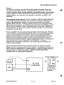
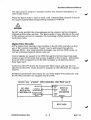
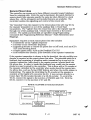
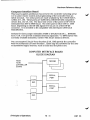
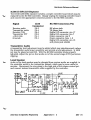
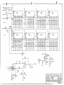
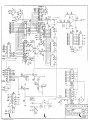
An on-board 21 volt supply (U24) provides the programming voltage
required for the older 2815 or 2816 E2PROMs. The 21 volt supply is
controlled by the microcomputer software and is kept off unless new data is
being programmed into the E2PROM. The 21 volt supply is not needed with
the 8K byte 9864 E2PROM. When the 9864 is installed instead of the
MX-l/2815's, U24 should be removed to avoid the possibility of damage due
to tum-on of the 21 volt supply.
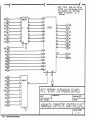
Another memory expansion board. the MX-2. may plug into the BUS
connector of the Main Controller Board to provide an additional 32K bytes of
program memory using a 27256 EPROM.
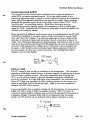
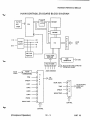
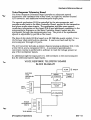
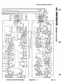
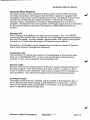
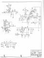
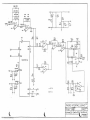
The repeater receiver audio is processed by the controller to remove
squelch tail and Touch-Tone and to provide a degree of automatic gain
control to reduce level variations through the repeater. The receiver audio
is pre:.filtered (low pass, U43) to limit its bandwidth before being applied to
the aUQio delay line. The audio passes through a gate (U45). then is delayed
75 ms-;in the delay line (U35). Post fIltering (U43) removes high frequency
clock:"fomponents generated in the delay line. The delayed audio passes
though an agc circuit (U36) whose control voltage is derived from the
undelayed receiver audio, providing a "predictive attack" agc characteristic.
The processed receiver audio is then available with the controller's other
audio inputs to be switched and mixed.
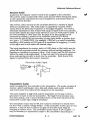
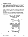
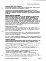
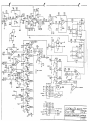
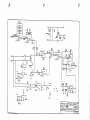
1\vo audio mixers (U 17) combine audio signals under computer control to
drive the repeater's transmitter and the phone line. Each input to the
mixers has its own level adjust and is Switched independently into the
mixers. In addition, an unswitched input is available to each mixer for
expansion. The mixer outputs drive the repeater's transmitter and the
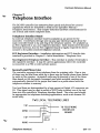
Telephone Interface Board.
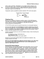
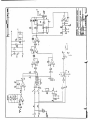
One of several audio sources is selected under computer control (U31) to
drive the Touch-Tone receiver. A bandsplit filter (U40) separates the high
and low tone components of the Touch-Tone signal, squares them up, and
applies them to the decoder inputs (U41). The logic outputs of the decoder
can be read by the microcomputer to determine. what Touch-Tone keys have
been sent to the controller (U42).
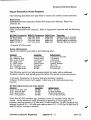
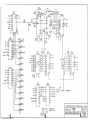
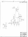
Buffered logic I/O interfaces the microcomputer to the other equipment in
the repeater system including the receiver and transmitter, link equipment,
courtesy tone select circuits, and various other equipment to be controlled
at the site (U29, U30, U19, U20, Q9-21). Inputs are TIL and CMOS
compatible Darlington transistor arrays while outputs are high voltage, high
current power FET transistors capable of sinking current to ground ("open
collector").
(Principles of Operation)
12 - 4
8/87 V3