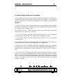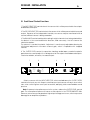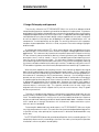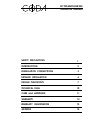
1
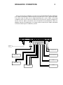
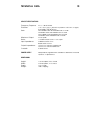
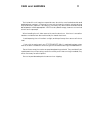
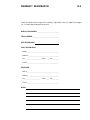
FET PREAMPLIFIER 02b
OPERATION MANUAL
T
E
C
H
N
O
L
O
G
I
E
S
I
N
C
.
SAFETY PRECAUTIONS
1
INTRODUCTION
2
INSTALLATION CONNECTIONS
3
DETAILED INSTALLATION
4
DESIGN PHILOSOPHY
7
TECHNICAL DATA
10
CARE and HANDLING
11
WARRANTY
12
WARRANTY REGISTRATION
13
ADDRESS
14
SAFETY PRECAUTIONS
1
CAUTION
WARNING
!
CAUTION: TO PREVENT ELECTRIC SHOCK,
DO NOT REMOVE COVER. NO USER
SERVICEABLE PARTS INSIDE, REFER
SERVICING TO QUALIFIED SERVICE
PERSONNEL.
THIS SYMBOL IS TO ALERT YOU OF THE
PRESENCE OF UNINSULATED DANGEROUS VOLTAGE WITHIN THE UNIT'S
ENCLOSURE THAT MAY BE OF SUFFICIENT MAGNITUDE TO CONSTITUTE A
RISK OF ELECTRIC SHOCK.
!
THIS SYMBOL IS INTENDED TO ALERT
YOU OF THE PRESENCE OF IMPORTANT
OPERATING AND MAINTENANCE
INSTRUCTIONS IN THE LITERATURE
ACCOMPANYING THE UNIT.
WARNING: TO PREVENT FIRE OR SHOCK HAZARD, DO NOT
EXPOSE THIS UNIT TO RAIN OR MOISTURE. TO
AVOID ELECTRICAL SHOCK, DO NOT OPEN THE
UNIT. REFER SERVICING TO QUALIFIED PERSONNEL.
CAUTION -
Never install or remove the power cord from the chassis
unless it has been disconnected from the AC power source
first.
Never pull on the power cord when removing it from an AC
power source. Grasp it by the plug.
Do not leave the power cord connected to an AC power
source unless it is connected to the unit.
It is recommend that during extended periods of nonuse
that the units power cord be unplugged from its AC power
source.
Route the AC power cord so that it will not be damaged or
walked on.
INTRODUCTION
2
This preamplifier is a precision device, designed in an effort to provide the listener with
unmatched sound quality, design, and construction. In order to operate your preamplifier
properly and to realize all of the capabilities of the FET PREAMPLIFIER 02b, we recommend
that you read this entire manual carefully.
INSTALLATION CONNECTIONS
3
The first section of the installation instructions for the FET PREAMPLIFIER 02b is a diagram
of the basic configuration required to bring the preamplifier into an operating mode.
These brief steps will allow you to begin operating your system. Make sure during
installation that the level control is turned fully counter clockwise, all other components
are off, and AC power connections are interrupted to the preamplifier. While the
diagram may be self explanatory, we strongly recommend that you read the detailed
instructions following this introductory section.
!
~
AC LINE INPUT
SEE SERIAL TAG FOR
POWER REQUIREMENTS
FOR CONTIMUED PROTECTION AGAINST
SHOCK OR FIRE HAZARD,DO NOT EXPOSE
THIS UNIT TO RAIN OR MOISTURE.
BALANCED OUTPUT
LEFT
RIGHT
UNBALANCED OUTPUT
LEFT
RIGHT
LEFT
OUT
RECORDER
IN
RIGHT
LEFT
VIDEO
RIGHT
LEFT
TUNER
RIGHT
LEFT
RIGHT
UNBALANCED DISC
LEFT
RIGHT
BALANCED DISC
LEFT
RIGHT
BALANCED DISC
UNBALANCED DISC
POWER AMP
TUNER
POWER AMP
OUTPUT
INPUT
RECORDER
VIDEO
DETAILED INSTALLATION
4
I. Set up and Installation
WARNING: NEVER OPERATE THIS UNIT WITH THE TOP COVER REMOVED. NEVER MAKE ANY
INTERNAL ADJUSTMENTS WHILE THIS UNIT IS CONNECTED TO AN AC POWER SOURCE.
1. Position the FET PREAMPLIFIER 02b in the space which you have chosen, leaving
enough space to connect the ancillary components of your audio system, and the AC
power cord for the preamplifier. Although the FET PREAMPLIFIER 02b has the ability to
reject external fields that produce system noise, it is recommended that the unit not be
placed near any sources of strong electromagnetic energy.
2. Before installing the preamplifier make sure all of the power switches of any associated
components are switched off. If any of your other audio components do not have power
switches, make sure they are unplugged from their AC power source.
!
Note: The Operating Voltage of the FET PREAMPLIFIER 02b is convertible in
order that it may be used worldwide. Contact your dealer to arrange
altering the operating voltage.
DETAILED INSTALLATION
5
II. Source-Output, and Power Connections
The input and output connectors are clearly marked on the rear lip of the top cover. It
is important to remember the correct left or right channel orientation. The function and
channel markings on the rear panel correspond to the front panel controls and their
signal paths.
They are:
1. The BALANCED DISC inputs should be attached to the balanced outputs of a compact
disc player or phono stage. The balanced XLR pin configuration is as follows; ground is
pin 1, positive is pin 2, negative is pin 3.
2. The UNBALANCED DISC, TUNER, and VIDEO input connections are all line level inputs,
requiring only the insertion of the RCA plugs.
3. The RECORDER inputs should be attached to the outputs of the corresponding
recording device; alternately, they may be used as additional line inputs.
4. The RECORDER outputs should be attached to the inputs of the corresponding
recording device.
5. The unbalanced OUTPUTS should be attached to the amplifier inputs either directly, or
through a crossover or processor, as appropriate to the application.
6. The BALANCED OUTPUTS should be attached to the balanced inputs of the amplifier,
either directly or through a crossover or processor, as appropriate to the application. The
balanced XLR pin configuration is as follows; ground is pin 1, positive is pin 2, negative is
pin 3.
7. The AC LINE INPUT should be attached to the power cable provided with the preamplifier. After making the appropriate connections and rotating the level control fully
counter clockwise, insert the three prong safety plug into an appropriate AC power
source. Once the FET PREAMPLIFIER 02b is properly connected, the LED on the front panel
will light. At this point, you may switch on your chosen ancillary components including
the power amplifier.
6
7
!
~
AC LINE INPUT
SEE SERIAL TAG FOR
POWER REQUIREMENTS
FOR CONTIMUED PROTECTION AGAINST
SHOCK OR FIRE HAZARD,DO NOT EXPOSE
THIS UNIT TO RAIN OR MOISTURE.
5
BALANCED OUTPUT
LEFT
RIGHT
UNBALANCED OUTPUT
LEFT
RIGHT
4
LEFT
OUT
RECORDER
IN
RIGHT
LEFT
3
1
2
VIDEO
RIGHT
LEFT
TUNER
RIGHT
LEFT
RIGHT
UNBALANCED DISC
LEFT
RIGHT
BALANCED DISC
LEFT
RIGHT
DETAILED INSTALLATION
6
III. Front Panel Control Functions
1. The INPUT SELECTOR control selects the source which will be presented to the outputs
and balanced outputs.
2. The RECORD SELECTOR control selects the source which will be presented to the record
output. Because of the independent controls, one source may be monitored while a
second, different source is being recorded.
3. The BALANCE control works by attenuating the right channel when being rotated from
the detent in the counterclockwise direction, and conversely, the left channel for
clockwise rotation.
The element is conductive plastic. Adjustment is continuously adjustable allowing for
infinitesimal adjustments to match channel gain, which is impossible with stepped
controls.
4. The OUTPUT LEVEL control is a precision tracking, audio taper, conductive plastic
potentiometer used to adjust the voltage level at the outputs and balanced outputs.
Clockwise rotation, of course, increases output.
1
2
INPUT SELECTOR
RECORD SELECTOR
BALANCED DISC
UNBALANCED DISC
3
4
BALANCE
OUTPUT LEVEL
RECORDER OFF
VIDEO
TUNER
TUNER
VIDEO
UNBALANCED DISC
RECORDER
BALANCED DISC
FET PREAMPLIFIER 02b
Select a source with the INPUT SELECTOR switch and advance the OUTPUT LEVEL
control to the level you wish. Keep in mind that your input sources will vary in level which
can, when switching from one input to another, abruptly yield uncomfortable sound
pressure.
Note: If a power interruption occurs to the system, reduce the OUTPUT LEVEL control
gain. The resumption of power will cause no noise pulses in the FET PREAMPLIFIER 02b.
However, some sources may produce high output voltages on turn on, which may cause
damage to an amplifier or speakers .
DESIGN PHILOSOPHY
7
I. Design Philosophy and Approach
The circuitry utilized in the FET PREAMPLIFIER 02b is the result of an advanced and
complete design process combining innovation and proven fundamentals. This process
avoids both the limitations of total adherence to convention and the flaws resulting from
inappropriate application of clever circuit gimmicks. Our approach demands painstaking
consideration of every facet of each design choice regardless of how small. Analytical,
as well as subjective techniques are all applied in an open-minded fashion with “no
compromise” musical perfection as the goal. The resulting refinement of the product
escapes simple explanation. With this in mind, we present here a few design highlights
and concepts.
All voltage gain is derived from FETs. While careful design can yield good results from
any device type, FETs consistently seem to have the edge in voltage gain and interface
applications. This is borne out by superior sonic qualities observed in subjective testing.
FETs are inherently transconductance devices, meaning that an input voltage controls
an output current. In other words, it “senses” the audio signal without drawing current
from the source to provide an output. This eliminates complex interactions with the
source allowing maximum performance from each system element and greatly reducing
the chance of cable characteristics altering the sound. The absence of input current in
FETs also allows high bias currents for linearity and speed without sacrificing DC parameters.
While excellent capacitors for coupling use exist, there can be no doubt that a signal
path free of coupling caps yields the best possible signal integrity. The DC stability of the
circuit eliminates the need for any questionable DC servo circuits or coupling capacitors.
We make no AC compromises for DC performance, however. Our key design choices
provide not only inherent DC stability, but also optimized AC performance throughout
the audio region and well beyond. These choices include the use of top quality dual FETS
in differential configurations for all voltage gain. Because the signal in these stages is
handled in a balanced manner, rejection of unwanted noise and modulation from
external sources is extremely high. This rejection extends even to noise which may
originate within the circuit from support circuity such as current sources. Stray RF signals
are also rejected well.
The class A complimentary followers used to drive the preamp output are of such
speed, linearity, and low output impedance that no feedback correction is required or
used. The advantage of this is that the circuit’s perfect stability and transient response
are preserved into a wide range of difficult and unpredictable loads. Variation in sound
which could occur through interactions with interconnect cables and other system
elements are thus avoided.
To accomplish balanced inputs and outputs, the FET PREAMPLIFIER 02b uses simple
very high performance inverters. The most commonly acknowledged advantage of this
is rejection of stray noise pickup, but improvements in distortion and bandwidth may
occur also.
The FET PREAMPLIFIER 02b controls provide an off position for the recording output. This
completely disconnects the recording system from the main system to prevent possible
interactions which may affect sound quality.
DESIGN PHILOSOPHY
8
The requirements of a power supply for flawless audio reproduction are straightforward
but important. The supplies in the FET PREAMPLIFIER 02b take a very direct approach to
high performance. First, a top quality shielded toroid transformer with plenty of reserve
current capability is used. About 28,000 uF of capacitance with very low ESR and
inductance provides good passive filtering. A reference voltage is developed by
delivering a constant current to zener diodes. The resulting voltage is heavily filtered and
delivered to each stage through independent class A followers which completely
decouples the stages. The resulting non-reactive low impedance over an extremely
wide bandwidth yields a perfect power source for the individual circuits. The simplicity
and absolute stability of the supplies removes the chance of unpredictable interactions
which may occur with the more elaborate, high feedback circuity often used.
Most companies in the upper end of the audio industry use either sheet metal or
formed aluminum. By contrast, the FET PREAMPLIFIER 02b has all structural parts made of
machined extruded aluminum. The advantage of this over an all stamped chassis is that
the machined metal can be worked more precisely allowing us to work on tighter
tolerances and use PC mounted parts more easily. Moreover such a design allows easier
servicing either for repair or for future upgrading. From the standpoint of appearance,
a machined surface can be contoured in a far more precise manner, giving the final
product a more seamless appearance.
DESIGN PHILOSOPHY
9
II. Parts' Quality
1. Finishes - All exterior and interior metal parts are anodized. While paint may be more
impact resistant, the anodized surface is more resistant to solvents and prevents corrosion.
Moreover, the anodized parts' appearance can be enhanced by either graining or
bead-blasting the surface.
2. Circuit Board - Circuit boards are fiberglass epoxy with gold plating over a tin/nickel
barrier. This gold layer will not corrode, while the barrier plate prevents the gold from
migrating to the lower copper layer and detracting from its appearance.
3. Resistors - All are high reliability metal film 1% resistors.
4. Capacitors - All capacitors have been eliminated where possible on the basis that “no
cap is better than the best cap". The only electrolytics used are in the power supply where
large numbers provide enormous filtering capacitance for the supply.
5. Semiconductors - There are no integrated circuits (IC) to be found in this product. Very
high quality dual FETs are the only source of voltage gain and were selected for their
superb noise performance and precision matching. The remaining semiconductors are
also of very high quality, each possessing parameters ideally suited for the specific
application.
6. Potentiometers - The volume controls are conductive plastic. These pots track with little
error and are totally neutral.
7. Connectors - Coda employs a standard RCA configuration with a gold plated case.
The balanced connectors are Neutriks from Switzerland.
8. Wire - All signal wire has been eliminated whenever possible. Where wire is used, Coda
employs silver plated copper, 141 strand, 18 guage wire with a silicone insulation.
TECHNICAL DATA
10
CIRCUIT SPECIFICATIONS
Frequency Response:
Distortion:
DC to -3 dB @ 200 kHz
< .01 % from 10 Hz to 40 kHz @ 6V peak into 600 Ohms or higher,
shunted by 1000 pF or less .
Gain:
Maximum Output:
Noise:
Input Impedance:
Output Impedance:
Crosstalk:
POWER SUPPLY
with unbalanced in and unbalanced out 14 dB
with balanced in and unbalanced out 14 dB
with unbalanced in and balanced out 20 dB
with balanced in and balanced out 20 dB
12 Volts peak
> 100 dBA referenced to 1 Volt output
unbalanced 20 k Ohms
balanced 20 k Ohms
15 Ohms non-reactive unbalanced
30 Ohms non-reactive balanced
70 dB @ 20 kHz
independently regulated with shielded toroidal transformer and
28,000 uf of capacitance
DIMENSIONS
Height:
Width:
Depth:
Weight:
1.75" Faceplate, 2.35" Overall
19.0" Faceplate, 17.0" Chassis
9.75" Overall
14 lbs. Shipping
CARE and HANDLING
11
The interior of the unit requires no special care, due to the use of sealed controls and
gold plating on contacts. If it becomes necessary to clean the exterior, a simple dusting
may be all that is required. If a cleaner is necessary, any dilute commercial ammonia
based product will be appropriate. NEVER use any abrasive rags, cleaners or chemical
solvents on the preamp.
When handling the unit, take care not to mar the aluminum. Aluminum is a medium
hardness metal and can be scratched by the harder tool steels.
Avoid exposing the unit to direct sunlight, and keep it away from sources of intense
heat.
If you wish to rack mount your FET PREAMPLIFIER 02b, it is advised to place nylon
washers under the heads of the mounting screws to avoid scratching the anodized finish.
Do not throw away the carton or associated packing material. They are ideal if you
need to pack the unit for moving, and in the unlikely event that servicing is needed, they
will be necessary for safe shipment.
Be sure to provide adequate insurance when shipping.
WARRANTY
12
I. Warranty- Any failure of the FET Preamplifier 02b to operate or to meet specifications,
applicable at time of manufacture, due to a manufacturing defect or component
failure, will be corrected by Coda Technologies, Inc. without charge for parts, or labor
for a period of ten years from date of original purchase. Coda Technologies, Inc. will
provide for surface transportation to and from the factory from an authorized Coda
Technologies, Inc. dealer for a period of one year from date of purchase.
II. Procedure- If the FET Preamplifier 02b should require service under warranty, take it with
proof of purchase date, with its carton and packing material, to a Coda Technologies,
Inc. dealer. The dealer will arrange for service. Direct shipments to the factory will be
accepted at the discretion of the company. Coda Technologies, Inc. products
purchased outside of the U.S. will be covered by those warranty conditions extended by
the importing distributor which may differ in some respects from those given above.
Warranty service, if required, is the responsibility of the importing distributor. If a Coda
Technologies, Inc. product is removed from the country of original purchase, Coda
Technologies, Inc. distributors or dealers are not obligated by the conditions of this
warranty and repairs will be affected at their discretion.
III. Exclusion of Coverage- At the sole opinion of Coda Technologies, Inc. the following
situations are specifically excluded from coverage:
1. Any FET Preamplifier 02b not operated in accordance with the instructions contained
in this manual, or otherwise subjected to abuse, tampering, modification, accidental
damage, or serial number defacement.
2. Damage to other property caused by any defects in this product, damages based
upon inconvenience, loss of use of the product, loss of time, commercial loss, or any other
damage whether incidental, consequential, or otherwise.
3. It is Coda Technologies, Inc. policy to extend coverage when reasonable doubt exist;
however, freight charges will be billed for any units returned under warranty and found
by the company to be operating according to specification.
This warranty gives you specific legal rights, and you may also have other rights which
vary from state to state.
Coda Technologies, Inc. continually researches new techniques, designs, and
construction methods and so reserves the right to introduce refinements into current
product lines without notice or obligation. The company may offer product modifications
to make these refinements available to earlier production units.
WARRANTY REGISTRATION
Fill in and retain this copy of the warranty registration sheet for your records .
MODEL DESIGNATION:__________________________________
SERIAL NUMBER:______________________________________
DATE OF PURCHASE:
PLACE OF PURCHASE
Dealer:___________________________________________
Address:__________________________________________
City:_____________________ State:____ Zip:__________
Phone:____________________________________________
PURCHASER
Name:_____________________________________________
Address:__________________________________________
City:_____________________ State:____ Zip:__________
Phone:____________________________________________
NOTES:
13
WARRANTY REGISTRATION
13.5
Please fill in and send this copy of the warranty registration sheet to Coda Technologies,
Inc. Include copy of proof of purchase.
MODEL DESIGNATION:__________________________________
SERIAL NUMBER:______________________________________
DATE OF PURCHASE:
PLACE OF PURCHASE
Dealer:___________________________________________
Address:__________________________________________
City:_____________________ State:____ Zip:__________
Phone:____________________________________________
PURCHASER
Name:_____________________________________________
Address:__________________________________________
City:_____________________ State:____ Zip:__________
Phone:____________________________________________
NOTES:
ADDRESS
Coda Technologies, Inc.
9941 Horn Road Suite A
Sacramento, CA 95827
Phone: (916) 363-4653
Fax:
(916) 363-4627
14