1
User's G uide
Gigabit Ethernet Switch
24-port 10/100Mbps Switch
Optional with Two 1000Mbps
Mini GBIC Fiber Modules
TABLE OF CONTENTS
1
UNPACKING INFORMATION..................................................................4
2
PRODUCT INTRODUCTION...................................................................5
2.1
KEY FEATURES ..............................................................................5
2.2
THE FRONT PANEL .........................................................................5
2.2.1
100BASE-TX TP Port ......................................................5
2.2.2
1000BASE-LX Fiber Ports (optional) ...............................5
2.2.3
1000BASE-SX Fiber Ports (optional) ...............................5
2.2.4
Cabling ............................................................................5
2.2.5
2.3
Status LEDs.....................................................................6
THE REAR PANEL ...........................................................................6
2.3.1
ON/OFF ("Reset") Switch ................................................6
2.3.2
Power Socket ..................................................................6
2.3.3
Console Port....................................................................7
2.4
TO LOCATE THE SWITCH ON A DESKTOP.............................................7
2.5
RACKMOUNT PLACEMENT ................................................................7
3
SMART FUNCTIONS SETTINGS............................................................8
3.1
START SMART FUNCTIONS...............................................................8
3.2
POWER ON SELF TESTING: .............................................................8
4
USE FUNCTION MENU ..........................................................................9
4.1
MAIN MENU ....................................................................................9
4.2
PORT STATUS ................................................................................9
2
4.3
PORT CONFIGURATION .................................................................. 11
4.3.1
Trunk Configuration ....................................................... 11
4.3.2
VLAN Configuration ....................................................... 12
4.4
QOS CONFIGURATION .................................................................. 14
4.4.1
TOS/Diff Serv. Priority.................................................... 14
4.4.2
802.1p Priority ............................................................... 14
4.4.3
Adapted Flow Control .................................................... 14
4.4.4
PRIORITY CONFIGURATION ............................................................ 15
4.6
MISC CONFIGURATION .................................................................. 16
4.7
5
6
Priority Weighted Ration ................................................ 15
4.5
4.6.1
MIB Counter .................................................................. 17
4.6.2
Device Feature .............................................................. 18
4.6.3
Global Configuration ...................................................... 19
4.6.4
Security Configuration ................................................... 20
4.6.5
Load Factory Default ..................................................... 20
4.6.6
Overview .......................................................................21
4.6.7
Diagnostics.................................................................... 21
PASSWORD .................................................................................. 22
HELPFUL SUGGESTIONS ................................................................... 24
5.1
PRIOR TO INSTALLATION ................................................................ 24
5.2
FAST ETHERNET & GIGABIT ETHERNET........................................... 24
5.3
MAC ADDRESS TABLE .................................................................. 24
PRODUCT SPECIFICATIONS...............................................................25
3
1
UNPACKING INFORMATION
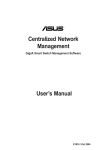
Thank you for purchasing this Gigabit Switch. Before continuing, please check the contents of the
product package. This product package should contain the following items:
.One Switch
.One Power Cord
.One Console Cable
.Four Rubber Feet (for desktop placement)
.One Rackmount Kit
.This User’s Guide
If anything is missing, please contact your place of purchase immediately.
Switch
Power Cord
Console Cable
Rackmount Kit
Rubber Feet
User’s Guide
4
2
PRODUCT INTRODUCTION
2.1
Key Features
. Auto-negotiation, Half-/Full-duplex and Flow-control for Flexible and Reliable Control on Packet
Transactions
. Provides Console Port for Easy Configuration
. Supports Broadcast Storm Filtering Control and Trunking Function (8 groups) for Enhanced
Network-wide Reliability and Efficiency
. Supports up to 32 VLAN Groups for Port-based and 802.1Q VLAN
. Supports Per-port Bandwidth Control and Priority Tag Insert and Remove Function
2.2
The Front Panel
2.2.1
100BASE-TX TP Port
Each of the twenty-four (24) 10/100Mbps ports provide an independent bandwidth for attached
devices. In addition, each port is supported by an Auto-Negotiation function that automatically
senses for the attached device’s fastest possible 100BASE-TX port speed, and then automatically
sets the port to operate at that speed. With Auto-MDI/MDI-X function, any port can be used for
connecting to another switch or hub using a straight-through CAT.5 cable.
2.2.2
1000BASE-LX Fiber Ports (optional)
Implementing long-wavelength laser transmissions, the optional fiber ports provide links of up to
550 meters using multi-mode cable and runs of 10 Kilometers when single-mode fiber cable is
used.
2.2.3
1000BASE-SX Fiber Ports (optional)
Implementing short-wavelength laser transmissions, the optional fiber ports provide links of up to
220 meters over 62.5-micron multi-mode cable or 550 meters using 50-micron multi-mode fiber
optic cable.
2.2.4
Cabling
For Fiber cable:
1000BASE-LX – To transmit at 1000Mbps requires Single-mode or Multi-Mode fiber cable.
1000BASE-SX –To transmit at 1000Mbps requires Multi-Mode fiber cable.
For TP (Twisted Pair) cable:
100BASE-TX - To transmit at 100Mbps requires Category 5 TP cabling
10BASE-T - When transmitting at 10Mbps Category 3, 4 or 5 TP cabling with RJ-45
sockets can be used.
5
Port Type
Cable Type
Connector
Fiber
1000BASE-LX
9/125 μm Single-Mode fiber cable
50/125 μm Multi-Mode fiber cable
62.5/125 μm Multi-Mode fiber cable
LC
1000BASE-SX
50/125 μm Multi-Mode fiber cable
62.5/125 μm Multi-Mode fiber cable
LC
100BASE-TX
Category 5 TP (Using min. 2 pairs)
RJ-45
10BASE-T
Category 3, 4 or 5 TP
RJ-45
TP
2.2.5
Status LEDs
This Switch comes with a complete range of LEDs. The table below lists each LEDs name, color
and a brief description of its function.
Name
Color
Function
PWR
Green
Lit: Power "On"
Ports 1~24
LINK/ACT
Yellow(10Mbps)
Green(100Mbps)
Lit: When the port has a valid physical connection with
another device.
Blinks: When the port is sending or receiving data (Activity).
Ports 1~24
FD/COL
Green
Lit: When the port is set to Full-Duplex mode.
Blinks: When a collision is detected in Half-Duplex mode.
Port 25,26
Fiber
Green
Lit: When the port has a valid physical connection with
another device at 1000Mbps.
Blink: When the port is sending or receiving data (Activity).
Ports 25,26
FD
Green
Lit: When the port is set to Full-duplex mode.
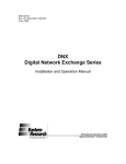
2.3
The Rear Panel
100-240V AC
50-60Hz
Console
OFF
2.3.1
ON
ON/OFF ("Reset") Switch
The power ON/OFF switch is located to the far right of the rear panel - next to the power
connector.
To reset the Switch, turn the power switch "OFF", then "ON".
Note: The Switch must be reset when the MAC address table needs to be rebuilt.
2.3.2
Power Socket
The Power Socket is designed to be used with the power cord included in the product package.
•Attach the female end of the power cord to the male power connector on the rear panel.
•Attach the male end of the power cord to a grounded power outlet.
6
2.3.3
Console Port
Used with the supplied console cable for switch configuration.
INSTALLATION
2.4
To Locate the switch on a desktop
.Attach the four rubber feet included in the product package to the bottom of the Switch, one in
each corner.
.Place the Switch on a clean, flat desk or tabletop close to a power outlet.
.Plug in all network connections and the power cord.
.Turn the power switch to "On".
2.5
Rackmount placement
.Attach one rackmounting bracket on each side of the Switch’s front panel and secure each
bracket with the provided screws.
.Use the other provided screws to secure the Switch to the rack.
7
3
SMART FUNCTIONS SETTINGS
3.1
Start Smart Functions
The Switch has built-in smart functions which when activated, can be used to manage the local
area network (LAN) more effectively. One can also use the default setting making the Switch to
operate as a dumb switch.
To configure the smart functions on the switch please follow the steps below:
.Use the supplied “RS-232” cable to connect the “console port” on the back of the switch to a
computer’s serial ports COM1 or COM2.
Note: If your Windows system doesn’t support Hyper Terminal, you have to install it first.
.Power “ON” the Switch
.Execute the “HyperTerminal” program:
Start Menu Æ Accessories Æ Communications Æ Hyper Terminal
.Setup the connection content of Hyper Terminal:
※ In connection tag, select which “COM” port is used to connect PC and the Switch.
※ Then press the “SETUP” button, set “Bits per second” to 19200, “Data bits” to 8,
“Parity” to None, “Stop bits” to 1, “Flow control” to None.
.After finishing the set-up in Hyper Terminal window, press any key to continue. Now the
computer can connect to Switch and use the user interface menu to select control functions.
Item
Setting
Port
COM
Baud rate
19200
Data bits
8 bits
Parity
None
Stop bits
1
Flow control NA
3.2
Power On Self Testing:
You can see the User Interface as below:
Please input the default password: 123
24-Port 10/100Mbps Switch
Optional with Two 1000Mbps Mini GBIC Fiber Modules
Password:
After entering the default username and password, the main switch configuration menu appears
on the screen.
8
4
USE FUNCTION MENU
4.1
Main menu
1. Port Status
2. Port Configuration
3. Trunk Configuration
4. VLAN Configuration
5. QoS Configuration
6. Priority Configuration
7. Misc
8. Password
Main Menu
=========
-------------------------------------------------------------------------------[1] Port Status
[2] Port Configuration
[3] Trunk Configuration
[4] VLAN Configuration
[5] QoS Configuration
[6] Priority Configuration
[7] Misc
[8] Password
-------------------------------------------------------------------------------Version : V1.00
Function Key
[ ]To select menu item, press item symbol. [F]Refresh Screen [X]Logout
4.2
Port Status
The port status screen displays the following information on each port:
Speed, Duplex, Link, Flow Control, Auto Negotiation, Trunk.
9
Port Status
===========
-------------------------------------------------------------------------------Port # | Speed | Duplex | Link | Flow Control | Auto Negotiation | Trunk
-------------------------------------------------------------------------------01
| 10M | Half
| Down | Enable
| Enable
|
02
| 10M | Half
| Down | Enable
| Enable
|
03
| 10M | Half
| Down | Enable
| Enable
|
04
| 10M | Half
| Down | Enable
| Enable
|
05
| 10M | Half
| Down | Enable
| Enable
|
06
| 10M | Half
| Down | Enable
| Enable
|
07
| 10M | Half
| Down | Enable
| Enable
|
08
| 10M | Half
| Down | Enable
| Enable
|
-------------------------------------------------------------------------------Function Key
[1/2]PageUp/PageDown [0]Return [F]Refresh Screen
Pressing [2] will show the same information for ports 9 to 16 and also for ports 17 to 24.
Port Status
===========
-------------------------------------------------------------------------------Port # | Speed | Duplex | Link | Flow Control | Auto Negotiation | Trunk
-------------------------------------------------------------------------------09
| 10M | Half
| Down | Enable
| Enable
|
10
| 10M | Half
| Down | Enable
| Enable
|
11
| 10M | Half
| Down | Enable
| Enable
|
12
| 10M | Half
| Down | Enable
| Enable
|
13
| 10M | Half
| Down | Enable
| Enable
|
14
| 10M | Half
| Down | Enable
| Enable
|
15
| 10M | Half
| Down | Enable
| Enable
|
16
| 10M | Half
| Down | Enable
| Enable
|
-------------------------------------------------------------------------------Function Key
[1/2]PageUp/PageDown [0]Return [F]Refresh Screen
10
4.3
Port Configuration
Display or change port configuration.
Port Configuration
==================
-------------------------------------------------------------------------------Port | Enabled | Speed
| Flow Control | Rx Bandwidth | Tx Bandwidth
|
| advertisement|
|
|
-------------------------------------------------------------------------------01 | Enable
|
Auto
| Enable
| Non-control | Non-control
02 | Enable
|
Auto
| Enable
| Non-control | Non-control
03 | Enable
|
Auto
| Enable
| Non-control | Non-control
04 | Enable
|
Auto
| Enable
| Non-control | Non-control
05 | Enable
|
Auto
| Enable
| Non-control | Non-control
06 | Enable
|
Auto
| Enable
| Non-control | Non-control
07 | Enable
|
Auto
| Enable
| Non-control | Non-control
08 | Enable
|
Auto
| Enable
| Non-control | Non-control
-------------------------------------------------------------------------------Function Key
[I/M/J/L]Up/Down/Left/Right [1/2]PageUp/PageDown [0]Return [F]Refresh Screen
[Space]Toggle State [R]Restart Auto Negotiation [S]Save
4.3.1
Trunk Configuration
Display or change Trunk configuration.
11
Trunk Configuration
===================
-------------------------------------------------------------------------------Trunking
| Enabled
-------------------------------------------------------------------------------Trunk1 (Port 01,13
) | Disable
Trunk2 (Port 02,14
) | Disable
Trunk3 (Port 03,04,15,16) | Disable
Trunk4 (Port 05,06,17,18) | Disable
Trunk5 (Port 07,08,19,20) | Disable
Trunk6 (Port 09,10,21,22) | Disable
Trunk7 (Port 11,12,23,24) | Disable
Trunk8 (Port 25,26
) | Disable
-------------------------------------------------------------------------------Function Key
[I/M]Up/Down [0]Return [F]Refresh Screen [S]Save
[Space]Toggle State
This switch supports up to 8 trunk groups. Depending on individual needs, the user can select
assigned 2 or 4 ports from port1 to port26 (10/100/1000 Mbps ports) to build a trunking group.
4.3.2
VLAN Configuration
Display or change VLAN configuration.
•VLAN Global Control
•VLAN Member Setup
VLAN Configuration
==================
-------------------------------------------------------------------------------[1] VLAN Global Control
[2] VLAN Member Setup
-------------------------------------------------------------------------------Function Key
[ ]To select menu item, press item symbol. [0]Return [F]Refresh Screen
12
VLAN Global Control
VLAN Global Control
===================
-------------------------------------------------------------------------------Function
| State
-------------------------------------------------------------------------------VLAN Function
| Disable
Unicast Packet Inter-VLAN Leaky
| Disable
ARP broadcast Packet Inter-VLAN Leaky | Disable
IP Multicast Packet Inter-VLAN Leaky
| Disable
802.1Q VLAN tag aware
| Disable
Ingress Rule for Acceptable frame types | Admit all Frames
Ingress Rule for Ingress Filtering
| Disable
-------------------------------------------------------------------------------Function Key
[I/M]Up/Down [0]Return [F]Refresh Screen [S]Save
[Space]Toggle State
VLAN Member Setup
13
VLAN Member Setup
[ Display Mode ]
-------------------------------------------------------------------------------VLAN | Port Base VLAN |VLAN|
Port (VLAN member)
Entry|
or
| ID |0|0|0|0|0|0|0|0|0|1|1|1|1|1|1|1|1|1|1|2|2|2|2|2|2|2
No. | 802.1Q VLAN
|
|1|2|3|4|5|6|7|8|9|0|1|2|3|4|5|6|7|8|9|0|1|2|3|4|5|6
-----+-----------------+----+-+-+-+-+-+-+-+-+-+-+-+-+-+-+-+-+-+-+-+-+-+-+-+-+-+|
|
||||||||||||||||||||||||||
-----+-----------------+----+-+-+-+-+-+-+-+-+-+-+-+-+-+-+-+-+-+-+-+-+-+-+-+-+-+|
|
||||||||||||||||||||||||||
-----+-----------------+----+-+-+-+-+-+-+-+-+-+-+-+-+-+-+-+-+-+-+-+-+-+-+-+-+-+|
|
||||||||||||||||||||||||||
-----+-----------------+----+-+-+-+-+-+-+-+-+-+-+-+-+-+-+-+-+-+-+-+-+-+-+-+-+-+|
|
||||||||||||||||||||||||||
-----+-----------------+----+-+-+-+-+-+-+-+-+-+-+-+-+-+-+-+-+-+-+-+-+-+-+-+-+-+|
|
||||||||||||||||||||||||||
-----+-----------------+----+-+-+-+-+-+-+-+-+-+-+-+-+-+-+-+-+-+-+-+-+-+-+-+-+-+|
|
||||||||||||||||||||||||||
-----+-----------------+----+-+-+-+-+-+-+-+-+-+-+-+-+-+-+-+-+-+-+-+-+-+-+-+-+-+Function Key
[I/M/J/L]Up/Down/Left/Right [1/2]PageUp/PageDown [0]Return [F]Refresh [S]Save
[E]Edit Mode [Enter]Update VLAN [A]Add VLAN [D]Del VLAN [Space]Toggle/Edit State
<E> to execute VLAN entry configure, <Enter> to update VLAN table!!
4.4
QoS Configuration
4.4.1
TOS/Diff Serv. Priority
When TCP/IP’s TOS/DiffServ (DS) based priority is applied, the Switch recognizes TCP/IP
Differentiated Services Code point (DSCP) priority information from the DS-field.
4.4.2
802.1p Priority
When 802.1p tag priority is applied, the Switch recognizes 802.1Q VLAN tagged packets and
extracts the 3-bit User Priority information from the VLAN tag.
4.4.3
Adapted Flow Control
The Switch can automatically turn off 802.3x Flow-control and Back-pressure Flow-control for 1~2
seconds whenever the port receives a high priority packet. Flow-control is re-enabled when no
priority packets are received for 1~2 seconds.
14
4.4.4
Priority Weighted Ration
The Switch supports two priority level queues. The queue service rate is based on the Weighted
Round Robin algorithm. The packet-based service weight ratio of high-priority and low-priority
queuing can be set as 4:1, 8:1, 16:1 or ‘Always high priority first’.
QoS Configuration
=================
-------------------------------------------------------------------------------Function
| State
-------------------------------------------------------------------------------TOS/Diff Serv. Priority
| Disable
802.1p Priority
| Disable
Adapted Flow Control
| Disable
Priority Weighted Ration(High:Low) | 16:1
|
-------------------------------------------------------------------------------Force Set High-Priority Port
-------------------------------------------------------------------------------[ ]Port01 [ ]Port05 [ ]Port09 [ ]Port13 [ ]Port17 [ ]Port21
[ ]Port02 [ ]Port06 [ ]Port10 [ ]Port14 [ ]Port18 [ ]Port22
[ ]Port03 [ ]Port07 [ ]Port11 [ ]Port15 [ ]Port19 [ ]Port23
[ ]Port04 [ ]Port08 [ ]Port12 [ ]Port16 [ ]Port20 [ ]Port24
[ ]Port 25
[ ]Port 26
Function Key
[I/M/J/L]Up/Down/Left/Right [0]Return [F]Refresh Screen [S]Save
[Space]Toggle State
4.5
Priority Configuration
Sets the priority QoS based on the physical port.
If a port is set as a high priority port, all packets received from that port will be treated as high
priority packets.
Bit value 1: Sets that port as a high priority port
Bit value 0: Sets that port as a low priority port
15
Priority Configuration
======================
-------------------------------------------------------------------------------Port | Tagging State
-------------------------------------------------------------------------------01 | Don't touch
02 | Don't touch
03 | Don't touch
04 | Don't touch
05 | Don't touch
06 | Don't touch
07 | Don't touch
08 | Don't touch
-------------------------------------------------------------------------------Function Key
[I/M]Up/Down [1/2]PageUp/PageDown [0]Return [F]Refresh Screen [S]Save
[Space]Toggle State
4.6
Misc Configuration
1. MIB Counter
2. Device Feature
3. Global
4. Security
5. Load Factory Default
6. Overview
7. Diagnostics
16
Misc Configuration
==================
-------------------------------------------------------------------------------[1] MIB Counter
[2] Device Feature
[3] Global
[4] Security
[5] Load Factory Default
[6] Overview
[7] Diagnostics
-------------------------------------------------------------------------------Function Key
[ ]To select menu item, press item symbol. [0]Return [F]Refresh Screen
4.6.1
MIB Counter
The MIB counters are 32-bit counters. After power on Reset, the counters are all reset to 0. A read
access of the MIB counter will NOT reset the counter to 0.
The time before the next read of the same counter should not be longer than the counter’s timeout.
The timeout of the 32-bit MIB counter depends on the object type and the port speed.
Packet counter timeout is calculated based on 64-byte packets and byte counter timeout is
calculated based on 1518 byte packets.
RX byte count: This counter is incremented once for every data byte of a received and forwarded
packet (includes both good and bad packets).
RX packet count: This counter is incremented once for every received and forwarded packet
(includes both good and bad packets).
TX byte count: This counter is incremented once for every data byte of a transmitted packet
(includes both good and bad packets).
TX packet count: This counter is incremented once for every transmitted packet (includes both
good and bad packets).
Drop packet count: This counter is incremented once for every drop of a received packet. Packet
drop events could be due to undersize, oversize, CRC error, lack of resources, local packet,
point-to-point control packet.
17
MIB Counter
===========
-------------------------------------------------------------------------------Port # | Tx Counter
| Rx Counter
| Drop Counter
| Unit: Packet
| Unit: Packet
| Unit: Packet
-------------------------------------------------------------------------------01
|
0
|
0
|
02
|
0
|
0
|
03
|
0
|
0
|
04
|
0
|
0
|
05
|
0
|
0
|
06
|
0
|
0
|
07
|
0
|
0
|
08
|
0
|
0
|
-------------------------------------------------------------------------------Note: Re-start polling MIB counter when you change unit (Byte/Packet).
0
0
0
0
0
0
0
0
Function Key
[1/2]PageUp/PageDown [0]Return [F]Refresh Screen [C]Clear All Counter
[P/X]Start/Stop Polling [T]Toggle Drop/CRC/Collision [B]Toggle Byte/Packet Unit
4.6.2
Device Feature
IGMP Snooping: The Switch supports ASIC-based IGMP (Internet Group Management Protocol)
snooping. This can be enabled and no other external CPU handling is required. It supports the
ability to parse the IGMP control protocol packets and IP multicast data packets and learn the
multicast router port and group address member ports into the multicast address table.
18
Device Feature
==============
-------------------------------------------------------------------------------Function
| State
-------------------------------------------------------------------------------IGMP Snooping | Disable
|
-------------------------------------------------------------------------------IP Multicast Router Port (Read Only) (Auto-refresh)
--------------------------------------------------------------------------------------------------------------------------------------------------------------Function Key
[0]Return [F]Refresh Screen [S]Save
[Space]Toggle State
4.6.3
Global Configuration
Half Duplex Back Pressure Flow: Set to globally enable or disable the Back-pressure
Flow-control ability of all ports.
Broadcast Storm Filtering Control: Set to disable broadcast packet (DA: ‘FFFFFFFFFFFF’)
strict flood mode and configure to loose flood mode. The control function is used under 802.3x
Flow-control mode. Strict flood mode will drop broadcast packets if any destination port member is
congested. Loose flood mode allows broadcast packets to be flooded to all non-congested ports.
Loop Detect: A loop-detection function is provided to notify if a network loop exists, either via a
visual LED, or via a register flag for smart applications.
Global Configuration
====================
-------------------------------------------------------------------------------Function
| Enabled
-------------------------------------------------------------------------------Half Duplex Back Pressure Flow
| Enable
Broadcast Storm Filtering Control | Disable
Loop Detect
| Disable
-------------------------------------------------------------------------------Function Key
[I/M]Up/Down [0]Return [F]Refresh Screen [S]Save
[Space]Toggle State
19
4.6.4
Security Configuration
Authentication Key: Used for security of the management operation.
The default Authentication key value is 0x2379. The Key value can be modified by the
administrator via a remote control packet. A received control packet with a valid Destination MAC
address but with an unmatched authentication key will be dropped with no reply. If the DA is a
broadcast address or is the address of another switch, it still will be relayed.
Default: 0x2379
Security Configuration
======================
-------------------------------------------------------------------------------Function
| Value
-------------------------------------------------------------------------------Authentication Key | 0x2379
|
-------------------------------------------------------------------------------Management Authorized Port Control
-------------------------------------------------------------------------------[V]Port01 [V]Port05 [V]Port09 [V]Port13 [V]Port17 [V]Port21
[V]Port02 [V]Port06 [V]Port10 [V]Port14 [V]Port18 [V]Port22
[V]Port03 [V]Port07 [V]Port11 [V]Port15 [V]Port19 [V]Port23
[V]Port04 [V]Port08 [V]Port12 [V]Port16 [V]Port20 [V]Port24
-------------------------------------------------------------------------------Function Key
[I/M/J/L]Up/Down/Left/Right [0]Return [F]Refresh Screen [S]Save
[Space]Toggle State [Enter]Edit OK
4.6.5
Load Factory Default
Load the default setting.
20
[V]Port 25
[V]Port 26
Misc Configuration
==================
-------------------------------------------------------------------------------[1] MIB Counter
[2] Device Feature
[3] Global
[4] Security
[5] Load Factory Default
[6] Overview
[7] Diagnostics
-------------------------------------------------------------------------------Load Factory Defaults & Hardware Reset (Y/N)?
Function Key
[ ]To select menu item, press item symbol. [0]Return [F]Refresh Screen
Load factory defaults & hardware reset. Initializing...initialization done.
4.6.6
Overview
It can show “Switch Name”, “Switch MAC ID”, “Chip Mode ID”, and “Vender ID”.
Overview
========
-------------------------------------------------------------------------------Description
| Data
-------------------------------------------------------------------------------Switch Name
| Switch-A
Switch MAC ID (Read Only) | 52:54:4C:01:02:03
Chip Model ID (Read Only) | 0xFF0C
Vender ID
(Read Only) | 0x40414243
-------------------------------------------------------------------------------Function Key
[0]Return [F]Refresh Screen
[E]Edit Switch Name [Enter]Edit OK
4.6.7
Diagnostics
It is easy for a host to do network connection diagnostics through a simple test packet, with or
without other hosts on the network. No IP assignment is required.
21
Diagnostics
===========
-------------------------------------------------------------------------------Fault Information
| VLAN ID | Port (VLAN member)
-------------------------------------------------------------------------------Trunk Link Warning | Trunk1(P01,13
)=>[ ] Trunk5(P07,08,19,20)=>[ ]
| Trunk2(P02,14
)=>[ ] Trunk6(P09,10,21,22)=>[ ]
| Trunk3(P03,04,15,16)=>[ ] Trunk7(P11,12,23,24)=>[ ]
| Trunk4(P05,06,17,18)=>[ ] Trunk8(25,26
)=>[ ]
-------------------------------------------------------------------------------Network Loop Fault | P01 P02 P03 P04 P05 P06 P07 P08 P09 P10 P11 P12 P13
Port Detected
|[][][][][][][][][][][][][]
|---------------------------------------------------------| P14 P15 P16 P17 P18 P19 P20 P21 P22 P23 P24 G01 G02
|[][][][][][][][][][][][][]
-------------------------------------------------------------------------------Note: [X]=>1.Detected some port link down, that belonged to the trunk group.
=>2.Some port loop detected.
Function Key
[F]Refresh Screen
4.7
[0]Return
Password
Configure the user password.
22
Main Menu
=========
-------------------------------------------------------------------------------[1] Port Status
[2] Port Configuration
[3] Trunk Configuration
[4] VLAN Configuration
[5] QoS Configuration
[6] Priority Configuration
[7] Misc
[8] Password
-------------------------------------------------------------------------------Enter Old Password ===> ***
Enter New Password ===> ***
Confirm New Password => ***
Version : V1.00
Function Key
[ ]To select menu item, press item symbol. [F]Refresh Screen [X]Logout
<Enter> to execute input action.
23
5
HELPFUL SUGGESTIONS
5.1
Prior to Installation
Before installing the Switch and connecting network devices, it is important to plan the network's
layout. Things you should consider include:
•Dedicated Bandwidth: File servers and other high-traffic hardware improve their performance if
they have their own dedicated 10Mbps, 100Mbps, or 1000Mbps bandwidth.
•Full-duplex: Determine which devices support Full-duplex connections.
•Fast Ethernet & Gigabit Ethernet: Make sure rules for cable lengths and categories are
followed. 100BASE-TX and 1000BASE-T have the same rules for cable and distance.
•Auto-negotiation: Devices with different speeds may be easily swapped when the other end of
the cable is fixed to a port with Auto-negotiation.
5.2
Fast Ethernet & Gigabit Ethernet
1000BASE-T is called "Gigabit Ethernet". In Gigabit Ethernet, data travels ten times faster
(1000Mbps) than in Fast Ethernet (100Mbps).
100BASE-TX is called "Fast Ethernet". In Fast Ethernet, data travels ten times faster (100Mbps)
than in traditional Ethernet (10Mbps).
Note: If your 10BASE-T network currently uses Category 5 TP cabling, you can instantly upgrade
the network to a 100BASE-TX network by changing network devices.
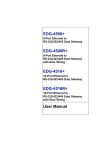
Note: Both 100BASE-TX and 1000BASE-T use Category 5 TP cabling. But 1000BASE-T must
use four pairs twisted pair wire. You should check that the Category 5 TP cabling you are using
has four pairs wire before you connect to a Gigabit device. The standard Category 5 TP cabling
pin-out as the following figures:
EIA/TIA
568A
1 W/Green
2 Green
3 W/Orange
4 Biue
5 W/Blue
6 Orange
7 W/Brown
8 Brown
P2
EIA/TIA
568B
P1 P3
P4
RJ-45 Jack Front View
5.3
1 W/Orange
2 Orange
3 W/Green
4 Biue
5 W/Blue
6 Green
7 W/Brown
8 Brown
P2
P1 P3
P4
RJ-45 Jack Front View
MAC Address Table
Every Ethernet data packet includes both source and destination addresses. This six (6) bytes ID
is called the MAC (Media Access Control) Address.
The Switch can automatically learn and store MAC addresses. However, the MAC address table
is volatile: it disappears when the Switch is powered “OFF” or reset.
Note: When the network needs reconfiguration, we recommend you to turn off the power first.
After all nodes have been moved, turn the Switch back "ON" to rebuild the internal MAC address
table.
24
6
Product specifications
Model
24-Port 10/100Mbps Switch Optional with Two 1000Mbps
Mini GBIC Fiber Module
Standards
.IEEE802.3: 10 BASE-T
.IEEE802.3u: 100 BASE-TX
.IEEE802.3z: 1000 BASE-X
.IEEE802.3x: Flow-control
Ports
.24 10/100Mbps Copper Ports
.2 1000Mbps Fiber module (Optional)
Media support
.10 Mbps: Category 3, 4 or 5 TP
.100Mbps: Category 5 TP
.1000Mbps: Duplex LC Connector Fiber
Bandwidth
.1000 BASE-T: 20/200/2000Mbps
.100 BASE-TX: 10/20/100/200Mbps
Forwarding/Filtering Rate
.14880 packets/second per port@10Mbps maximum
.148800 packets/second per port@100Mbps maximum
.1488000 packets/second per port@1000Mbps maximum
Duplex Modes
.Support Auto-negotiation and Auto-MDI/MDI-X functions
LED Indicators
.One LED displays PWR status
.For port 1 to 24 (10/100Mbps ports):
One (1) Yellow/Green LED per port for Link/ACT
One (1) LED per port for FDX/COL
.For port 25, 26 (Module ports):
One (1) LED per port for 1000Mbps LINK/ACT status
One (1) LED per port for FDX status
Power Supply
.Full range Auto-switching
.Input voltage: 100~240 +/-10%V AC/50~60Hz
Power Consumption
.36.4 Watt maximum
Environment
.Operating temp: 0~45°C(32~113°F)
.Storage temp: -20~70°C(-4~158°F)
.Humidity: 10%~90% Non-condensing
Certifications
.FCC Class A
.CE Mark
Dimensions
.442 x 44 x 185mm (17.4 x 1.73 x 7.28 inches)
25
P/N:1 2-00-0480-B1