1
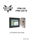
CAMBRIDGE USERS MANUAL CFP84 Family Panel Mount Rack Mount LCD Monitor User Guide 150-CFP-084(-) Contents Section 1 Display Set-up............................................................................................................... 3 Product Safety Precautions ................................................................................................ 3 Included Parts .................................................................................................................... 3 Connecting Your Display .................................................................................................... 4 Section 2 Getting Started.............................................................................................................. 5 Display Features ................................................................................................................. 5 Adjusting the Displays......................................................................................................... 5 Keyboard Layout & Function .............................................................................................. 5 OSD (On Screen Display) Adjustments ............................................................................. 5 OSD Membrane Layout...................................................................................................... 6 Adjustment Procedure ....................................................................................................... 7 Section 3 Touch Screen Set-up.................................................................................................. 10 Introduction to Touch Screen ........................................................................................... 10 Touch Screens Provided .................................................................................................. 10 Touch Screens and Special Drivers ................................................................................. 10 Section 4 Mounting Instructions.............................................................................................. 11 Panel Mounting................................................................................................................. 11 Rack Mounting.................................................................................................................. 11 Section 5 Touble Shooting Tips................................................................................................. 12 Section 6 Cleaning and Maintenance ........................................................................................ 14 Section 7 Appendices ................................................................................................................. 15 Appendix A - VGA Pin Assignments................................................................................. 15 Appendix B - RS-232 Pin Assignments ............................................................................ 15 Appendix C - NTSC/PAL and S-Video.............................................................................. 16 Appendix D - General Specifications ................................................................................ 17 Appendix E - Mounting Dimensions.................................................................................. 18 150-CFP-084(-) 2 1 Display Setup Section Product Safety Precautions Safety Precautions CAUTION: SHUT OFF YOUR TOUCH SCREEN BEFORE CLEANING!! IF YOUR DISPLAY HAS A TOUCH SCREEN PANEL, THE SCREEN WILL BE ACTUATED BY CLEANING. PRESSING ON THE SCREEN WHILE CLEANING WILL BE SEEN AS A TOUCH TO THE SYSTEM WHICH COULD CREATE A POTENTIALLY DANGEROUS CONDITION! • • • • • • • • Do not attempt to service this display yourself. The rear chassis has a seal so that non-qualified personnel will not expose themselves to dangerous voltages or other risks. To protect from electrical shock, unplug the display power supply from the wall before moving. Do not use this display near water. Do not place any heavy objects on the power cords. Damage may cause electrical shock. Unplug the power supply from the wall or unit if one of the following conditions exists: o Power cord or plug is damaged or frayed. o Liquid is spilled into the display or the display is exposed to rain or water. o The display does not operate normally when the operating instructions are followed. o The display has been dropped or the enclosure has been damaged. o The display exhibits a distinct change in performance, indicating a need for service. Ensure that sufficient space is available around the display to provide air circulation for cooling. Ensure that the ambient air temperature will not exceed the specified maximum temperature. Do not expose the display to direct sunlight or heat. Included Parts Open shipping container and lay all components on a flat clean surface. Your LCD monitor package will consist of the primary components listed below: • LCD Monitor • 6 ft Video Cable • 6 ft AC Power Cord • 6 ft RS-232 Touch Interface Cable (touch screen units only) • 6 ft USB Touch Interface Cable (touch screen units only) • Suitable Mounting Hardware (for use with Panel Mount or Rack Mount) • Documentation and Driver CD ROM • Users Manual 150-CFP-084(-) 3 Connecting Your Display Before progressing further, adjust your PC Video to VGA resolution (640 x 480) and 60Hz vertical refresh rate. 1. Connect all cables to the computer first. This includes the VGA cable, and if the unit has a touch screen, the RS-232 serial or the USB touch screen connection. 2. After connecting the cables between the LCD monitor and the computer, connect the supplied AC Power Cord to a suitable power source. 3. The LCD will immediately power up. 4. If your computer is off, turn on your computer. 5. Your display should now operate as a normal computer display – displaying the computers BIOS screens and booting into Windows or other operating system. NOTE: If for any reason the display goes blank and/or displays an “Out of Range” or “No Input Signal” message on the screen, your computer or video source may be putting out a signal that is incompatible with the LCD monitor. If this happens, you will need to adjust the computer to output a compatible video signal. Below are the most common reasons a display may not operate correctly: 1. The resolution is too high or low for the LCD or wrong sync signal configuration is provided. 2. The refresh rate is set too high. Refresh on an LCD is different than a CRT. Set the refresh to 60Hz. CRT’s need a high refresh rate to avoid flicker. The refresh rate has no impact on an LCD. 3. The power source is incorrect, or there is no power. Check if the rear LED is ON or blinking. If the LED is not lit, check to be sure there is power to the unit. 4. The unit is malfunctioning. If you believe this to be true, disconnect the video cable from the rear of the LCD and connect to a known good display. If an alternate display operates correctly, and the video is in a compatible range then contact Aydin Displays, Inc. technical support. 150-CFP-084(-) 4 2 Getting Started Section Display Features • • • • • The LCD is capable of displaying 262K colors in a continuous spectrum. The high contrast LCD enhances the image with no geometric distortion. The LCD directly accepts an Analog 3, 4 or 5 Wire RGB with sync input. The LCD is auto synchronous – adjusting the display to the appropriate VGA input. The LCD is supplied with an Anti-Glare Touch Screen or an Anti-Glare impact window on non touch screen models. Adjusting the Display The LCD display has an embedded microprocessor in the converter card which is the electronics that drives the LCD. In most cases the unit will require very little, if any, user intervention to operate correctly - that is to produce a sharp stable picture. The micoprocessor in the display has the capability to adjust itself to the computer to which it is attached. If the picture is not satisfactory, the first step is to allow the unit to attempt to adjust itself to your computer. The membrane keypad used for adjusting the display is below: Keyboard Layout and Function OSD (On Screen Display) Adjustments There are four membrane buttons located on the rear of the unit. They will activiate the OSD and allow navigation to all user required adjustments. 150-CFP-084(-) 5 OSD Membrane Layout Main Menu Automatic Adjustment Sub Adjustment Geometry & Color Balance Horizontal Position Horizontal Position Vertical Position Vertical Position Horizontal Size Horizontal Size Phase Phase Brightness Brightness Contrast Contrast Color Red, Green or Blue OSD Language English, Spanish, Dutch, French or Italian Advanced Factory Preset, OSD Horizontal Position, OSD Vertical Position Cancel 150-CFP-084(-) 6 Adjustment Procedure 150-CFP-084(-) 7 150-CFP-084(-) 8 The Aydin 150-CFP-084(-) 9 3 Touch Screen Set-up Section Introduction to Touch Screens Touch screen interfaces have become the standard interface in the past 5 years. They are rugged, reliable, extremely flexible and easier than ever to implement! The universal acceptance of the Windows GUI (Graphical User Interface) along with the extensive use of a mouse interface has significantly accelerated the use of a touch interface. Think of your touch screen as if it were a mouse. Touch Screens Provided 5 Wire Resistive RS-232 or USB Capacitive RS-232 or USB SAW RS-232 or USB Touch Screens and Special Drivers Software drivers for touch screen systems are provided in the Aydin Displays, Inc. accessory kit. It is always good to download the latest drivers from the respective web sites. Refer to the individual manufacturer’s documentation or contact the manufacturer to obtain special drivers: 3M Touch Additional drivers, manuals and instructions for touch systems can be found at: www.3m.com/3mtouchsystems Touch International Additional drivers, manuals and instructions for touch systems can be found at: www.touchintl.com ELO Touch Additional drivers, manuals and instructions for touch systems can be found at: www.elotouch.com/support/dnld.asp Follow the manufacturer’s instructions for installing special drivers. 150-CFP-084(-) 10 4 Section Mounting Instructions Panel Mounting Procedure 1. Cut and drill the panel to the proper size (see panel cutout in Appendix E). Measurements are shown in inches. 2. If access to the side of monitor is not available following installation, attach the power and video cables to the side of the monitor at this time. 3. Install the monitor in the prepared cutout. 4. Install the washers and lock nuts. 5. Tighten all mounting nuts evenly to approximately a torque of 24 inch-pounds. ATTENTION: Mounting nuts must be tightened to a torque of approximately 24 inchpounds to provide panel seal and avoid potential damage. Aydin Displays, Inc. assumes no responsibility for water or chemical damage to the monitor or other equipment within the enclosure due to improper installation. 6. Attach the power, video and touch screen cables (if applicable) to the side of the monitor. Rack Mounting Procedure 1. Position the monitor to the proper position in the rack. 2. Install the screws. Tighten all mounting screws evenly to approximately a torque of 23 inch-pounds. 3. Attach the power, video and touch screen cables (if applicable) to the side of the monitor. 4. If access to the side of the monitor is not available following the installation, attach the power and video cables to the side of the monitor at the same time 150-CFP-084(-) 11 5 Troubleshooting Tips Section No picture The signal cable should be properly connected to the display and computer. Try disconnecting the video cable from the display and connecting to another display if available to confirm the presence of proper video. Make sure the power is connected to the proper AC source. Make sure the resolution mode is supported by the display and check display settings of the PC. Confirm that the video cable is not defective. Image persistence Image persistence occurs when a ghost of an image remains on the screen after the screen image has been changed. Unlike a CRT monitor, an LCD monitor’s image persistence is not permanent. To erase an image ghost, turn the monitor off for several hours. What happens is that after extended periods of operation the liquid crystals “set”. To avoid this condition, install a screen saver program on the computer. Picture quality & image stability Check for proper video cable for proper grounding and shielding. Check the signal source for proper signal. Check for proper adjustment of the phase and frequency controls. Check for proper recommended signal timing. Green LED not lit 150-CFP-084(-) Check for proper power and power connections. 12 Display image is not properly sized Press the “Select” button to Auto Adjust the display. Adjust the Vertical and Horizontal size controls via the OSD (reference OSD Adjustments). Ensure that a supported mode is selected on the display card or system being used. Consult the display card or system manual for proper video. Image will not adjust Video timing outside of range. Use the on-screen menu to adjust the Clock Setting. Make sure timing is within VESA standard. Slight distortion in text or graphics Not working in native resolution. Display is present but “bars” appear or roll across screen Ground loop problem between computer and display. Vertical shaded bars on screen image Horizontal size is not properly adjusted. Adjust horizontal size. Image is not stable Monitor has incorrect or bad sync signals. Interference from adjacent equipment. Check for proper video cable installation. Replace suspected faulty cable. Check to ensure that the video source is within the display’s operating range. 150-CFP-084(-) 13 6 Cleaning & Section Maintenance Cleaning Occasionally clean the display panel and cabinet with a soft cloth dampened (not soaked) with a mild (non-abrasive) glass cleaner. Keep turning a fresh side of the cloth toward the screen surface to avoid scratching it with accumulated grit. NOTE: The solvent should be applied only to the cloth, NOT directly on the monitor screen. Do not use paper products as they may scratch the surface. To minimize the risk of abrasion, allow the screen to air dry. Special care should be taken when cleaning a touch screen or polycarbonate shield that is installed over the screen. Abrasive and certain chemical cleaners can damage the surface. Never use alcoholic or ammoniac cleaners to clean the polycarbonate shield or a touch screen. Replacing a Line Cord To avoid shock and fire hazards, the monitor’s power cord should be replaced if the insulation becomes broken or if it develops a loose internal connection. Other Maintenance Qualified service personnel should perform all maintenance, except for the power cord replacement described above. 150-CFP-084(-) 14 7 Appendices Section Appendix A – Video Pin Assignments Pin assignments for the HD15 Video Connector Pin 1 Pin 2 Pin 3 Pin 4 Pin 5 Pin 6 Pin 7 Pin 8 Red Video Green Video Blue Video Not Used Return Red Video Ground Green Video Ground Blue Video Ground Pin 9 Pin 10 Pin 11 Pin 12 Pin 13 Pin 14 Pin 15 No Connection Sync Ground Not Used Bi-Directional Data Horizontal Sync Vertical Sync Data Clock (SCL) Appendix B – RS-232 Pin Assignments Pin assignment for the 9 Pin Optional Touch Screen Connector Pin 1 Pin 2 Pin 3 Pin 4 Pin 5 Pin 6 Pin 7 Pin 8 Pin 9 150-CFP-084(-) DCD RD (Rx) SD (Tx) DTR SG DSR RTS CTS NC Data Carrier Detect Receive Data Transmit Data Data Terminal Ready Signal Ground Data Set Ready Request to Send Clear to Send No Connection 15 Appendix C – NTSC/PAL and S-Video S-Video S-Video, originally known as "Y/C Separated Video", is one of the higher quality ways to transmit a television signal from a peripheral device (DVD player, PlayStation 2, etc.) to a television. The way S-Video works is that it separates the color information (Chrominance) from the brightness (Luminance). By doing this, it reduces things such as color bleeding and dot crawl and greatly increases the general clarity and sharpness of the picture. The reason for this is that televisions are designed to display separate Luminance (Y) and Chrominance (C) signals. Composite Video Composite Video (RCA or BNC) is the old "AV" standard connector. The common RCA connector is color-coded Yellow for Composite video. The term "yellow-plug video" is recommended to help cut down on confusion between "composite" and "component" (which sound alike). 150-CFP-084(-) 16 Appendix D – CFP84 Specifications Active Screen Area Brightness 6.73” x 5.05” (170.9 x 128.2mm) 450 nits typical Contrast 500:1 Lamp Life 50K Max Screen Resolution VGA (640 x 480) Native Resolution (best picture) Sync Type VGA Separate H and V (5 Wire) ONLY 55/55 40/70 Reference PDF’s Section 7 16 Ga SS Al Machined .250” SS Machined (NEMA 4x) Reference PDF’s Section 7 Black Textured NEMA 4x Yes Yes RS-232 or USB No VGA (HD-15F) (female) 262,144 0° to 50° C 0° to 60° C 10% to 95% relative humidity non-condensing 4/12 and 4x 115/220VAC 30W Max View Angle L / R View Angle Up / Dn Installed Depth Chassis Construction Bezel Construction Bezel OD Bezel Finish (aluminum) Bezel Finish (stainless steel) Auto Adjust 5 Wire Touch Touch Interface Recessed Cable Exit PC Video Interface Colors Operating Temperature Storage Temperature Storage Humidity NEMA Front End Input Voltage Input Power NOTE: Does not include cable exit. Standard cable exit to the rear will add approximately 2” to the depth. With bottom exit cables, the cable hood extends down from the bottom edge of the display approximately 2”. 150-CFP-084(-) 17 Appendix E – Mounting Dimensions CFP84P1 Outline Dimensions 150-CFP-084(-) 18 Appendix E – Mounting Dimensions CFP84P1 Cutout Dimensions 150-CFP-084(-) 19