1
Features and Specifications Manual
(Australia and New Zealand)
NEC Business Solutions Ltd
A6-324000-642-05
Release 6.0
May 2003
NEC Business Solutions Ltd
Xen Master and Xen Axis Systems
A6-324000-642-05 - Release 6.0
May 2003
THIS PAGE INTENTIONALLY LEFT BLANK
ii
Features and Specifications Manual
Preface
GENERAL INFORMATION
The Xen Master and Axis Systems are feature-rich key systems that
provide over 200 features including Computer Telephony Integration, Least
Cost Routing, Automatic Call Distribution, ISDN-BRI Voice Trunks, LAN/
KTS Cabling Integration, and many others.
The Xen Master and Axis systems meet customer needs today and as
business expands the systems can be expanded to grow as well.
The Xen Master and Axis systems have a set of manuals that provide all the
information necessary to install and support the system. The manuals are
described in this preface.
THIS MANUAL
SUPPORTING
DOCUMENTS
This manual provides specific detailed information and specifications for all
features provided with the Xen Master and Axis systems for Australia and
New Zealand.
Xen Master and Axis Systems General Description Manual
This Manual provides general information about the system, its features,
system configuration and standards. This manual provides an overview of
the Xen Master and Axis Systems and can be used to present information
to potential customers.
Xen Master and Axis Systems Hardware Manual
The System Hardware Manual is provided for the system installer. This
manual has detailed instructions for installing the Xen Master and Axis
System KSUs, ETUs, Multiline Terminals, and optional equipment.
Xen Master and Axis Systems Programming Manual
This manual provides instructions for programming the Xen Master and Axis
system via a Multiline Terminal or PC.
Xen Least Cost Routing Manual
This manual provides instructions to the service technician for programming
the customer site for least cost routing.
A6-324000-642-05 - Release 6.0
May 2003
Xen Automatic Call Distribution Manual
This manual provides the service technician with instructions for
programming the ACD. This manual can also be used by the ACD
supervisor, at the customer site, to use to become familiar with the ACD/
MIS feature.
Features & Specifications Manual – Preface
iii
NEC Business Solutions Ltd
Xen Master and Xen Axis Systems
NEC shall not be liable for any direct, indirect, consequential or incidental
damages about the use of this equipment, manual or any related materials.
The information in this technical manual is advisory in nature and is subject
to change. NEC may make improvements and changes in the products
described in this manual without notice. Changes will be periodically made
to the information in the new editions.
Efforts have been made to ensure that the contents of this manual are
correct. Should you find any error, NEC welcomes your comments to
improve our communications, please contact NEC on 1800 036 136.
Contents of this manual are subject to change without prior notice at the
discretion of NEC Business Solutions Ltd.
This document has been prepared for the use of employees and customers
of NEC Business Solutions Ltd and may not be reproduced without the
prior, written approval of NEC Business Solutions Ltd.
Copyright 2003
NEC Business Solutions Ltd
635 Ferntree Gully Road
A6-324000-642-05 - Release 6.0
May 2003
Glen Waverley Vic 3150
iv
Preface – Features and Specifications Manual
Table of Contents
May 2003
Chapter 1
Introduction . . . . . . . . . . . . . . . . . . . . . . . . . . . . . . . . . . . . . .1
SECTION 1
SECTION 2
General Information . . . . . . . . . . . . . . . . . . . . . . . . . . . . . . . . . . . . . . . . . . 1
Multiline Terminals Used With The System . . . . . . . . . . . . . . . . . . . . . . . . 1
Chapter 2
Features. . . . . . . . . . . . . . . . . . . . . . . . . . . . . . . . . . . . . . . . . .3
SECTION 1
SECTION 2
General Information . . . . . . . . . . . . . . . . . . . . . . . . . . . . . . . . . . . . . . . . . . 3
Operating Procedures . . . . . . . . . . . . . . . . . . . . . . . . . . . . . . . . . . . . . . . . 5
A-1
Account Code Entry . . . . . . . . . . . . . . . . . . . . . . . . . . . . . . . . . . . . . . . . . . . . . . . . . . . 7
A-2
Account Code - Forced/Unverified . . . . . . . . . . . . . . . . . . . . . . . . . . . . . . . . . . . . . . . 11
A-3
Account Code - Forced/Verified . . . . . . . . . . . . . . . . . . . . . . . . . . . . . . . . . . . . . . . . . 15
A-4
Add-On Conference . . . . . . . . . . . . . . . . . . . . . . . . . . . . . . . . . . . . . . . . . . . . . . . . . . 19
A-5
All Call Page . . . . . . . . . . . . . . . . . . . . . . . . . . . . . . . . . . . . . . . . . . . . . . . . . . . . . . . . 21
A-6
Alphanumeric Display . . . . . . . . . . . . . . . . . . . . . . . . . . . . . . . . . . . . . . . . . . . . . . . . . 25
A-7
Ancillary Device Connection . . . . . . . . . . . . . . . . . . . . . . . . . . . . . . . . . . . . . . . . . . . . 29
A-8
Answer Hold . . . . . . . . . . . . . . . . . . . . . . . . . . . . . . . . . . . . . . . . . . . . . . . . . . . . . . . . 31
A-9
Answer Key . . . . . . . . . . . . . . . . . . . . . . . . . . . . . . . . . . . . . . . . . . . . . . . . . . . . . . . . 33
A-10 Assigned Night Answer (ANA) . . . . . . . . . . . . . . . . . . . . . . . . . . . . . . . . . . . . . . . . . . 35
A-11 Attendant Add-On Console . . . . . . . . . . . . . . . . . . . . . . . . . . . . . . . . . . . . . . . . . . . . 37
A-12 Attendant Camp-On . . . . . . . . . . . . . . . . . . . . . . . . . . . . . . . . . . . . . . . . . . . . . . . . . . 41
A-13 Attendant Positions . . . . . . . . . . . . . . . . . . . . . . . . . . . . . . . . . . . . . . . . . . . . . . . . . . 43
A-14 Attendant Station Outgoing Lockout . . . . . . . . . . . . . . . . . . . . . . . . . . . . . . . . . . . . . . 45
A-15 Attendant Transfer . . . . . . . . . . . . . . . . . . . . . . . . . . . . . . . . . . . . . . . . . . . . . . . . . . . 47
A-16 Automatic Answer with Delay Message . . . . . . . . . . . . . . . . . . . . . . . . . . . . . . . . . . . 49
A-17 Automated Attendant . . . . . . . . . . . . . . . . . . . . . . . . . . . . . . . . . . . . . . . . . . . . . . . . . 53
A-18 Automatic Callback . . . . . . . . . . . . . . . . . . . . . . . . . . . . . . . . . . . . . . . . . . . . . . . . . . . 59
A-19 Automatic Call Distribution (ACD) . . . . . . . . . . . . . . . . . . . . . . . . . . . . . . . . . . . . . . . 61
A-20 Automatic Call Distribution (ACD Plus) . . . . . . . . . . . . . . . . . . . . . . . . . . . . . . . . . . . 67
A-21 Automatic Day/Night Mode Switching . . . . . . . . . . . . . . . . . . . . . . . . . . . . . . . . . . . . 75
A6-324000-642-05 - Release 6.0
May 2003
A-22 Automatic Hold . . . . . . . . . . . . . . . . . . . . . . . . . . . . . . . . . . . . . . . . . . . . . . . . . . . . . . 77
A-23 Automatic Redial . . . . . . . . . . . . . . . . . . . . . . . . . . . . . . . . . . . . . . . . . . . . . . . . . . . . 79
A-24 Automatic Release . . . . . . . . . . . . . . . . . . . . . . . . . . . . . . . . . . . . . . . . . . . . . . . . . . . 81
A-25 Automatic Carrier Routing . . . . . . . . . . . . . . . . . . . . . . . . . . . . . . . . . . . . . . . . . . . . . 83
A-26 Automatic Trunk-to-Trunk Transfer . . . . . . . . . . . . . . . . . . . . . . . . . . . . . . . . . . . . . . 85
B-1
Background Music Over External Speakers . . . . . . . . . . . . . . . . . . . . . . . . . . . . . . . . 89
B-2
Background Music - Multiline Speaker . . . . . . . . . . . . . . . . . . . . . . . . . . . . . . . . . . . . 91
Features & Specifications Manual – Table of Contents
v
NEC Business Solutions Ltd
Xen Master and Xen Axis Systems
B-3
Barge-In . . . . . . . . . . . . . . . . . . . . . . . . . . . . . . . . . . . . . . . . . . . . . . . . . . . . . . . . . . . 93
B-4
Battery Backup - System Memory . . . . . . . . . . . . . . . . . . . . . . . . . . . . . . . . . . . . . . . 95
B-5
Battery Backup - System Power . . . . . . . . . . . . . . . . . . . . . . . . . . . . . . . . . . . . . . . . . 97
B-6
Busy Lamp Field on Multiline Terminals . . . . . . . . . . . . . . . . . . . . . . . . . . . . . . . . . . . 99
C-1
Call Alert Notification . . . . . . . . . . . . . . . . . . . . . . . . . . . . . . . . . . . . . . . . . . . . . . . . 101
C-2
Call Appearance Keys (CAP) . . . . . . . . . . . . . . . . . . . . . . . . . . . . . . . . . . . . . . . . . . 105
C-3
Call Arrival Keys (CAR) . . . . . . . . . . . . . . . . . . . . . . . . . . . . . . . . . . . . . . . . . . . . . . 107
C-4
Callback Request . . . . . . . . . . . . . . . . . . . . . . . . . . . . . . . . . . . . . . . . . . . . . . . . . . . 109
C-5
Caller ID Call Return . . . . . . . . . . . . . . . . . . . . . . . . . . . . . . . . . . . . . . . . . . . . . . . . 111
C-6
Caller ID - Incoming . . . . . . . . . . . . . . . . . . . . . . . . . . . . . . . . . . . . . . . . . . . . . . . . . 115
C-7
Caller ID - Outgoing . . . . . . . . . . . . . . . . . . . . . . . . . . . . . . . . . . . . . . . . . . . . . . . . . 121
C-8
Call Forward - All Calls . . . . . . . . . . . . . . . . . . . . . . . . . . . . . . . . . . . . . . . . . . . . . . . 125
C-9
Call Forward - Busy/No Answer . . . . . . . . . . . . . . . . . . . . . . . . . . . . . . . . . . . . . . . . 129
C-10 Call Forward - Off-Premise . . . . . . . . . . . . . . . . . . . . . . . . . . . . . . . . . . . . . . . . . . . . 131
C-11 Call Forward - Split . . . . . . . . . . . . . . . . . . . . . . . . . . . . . . . . . . . . . . . . . . . . . . . . . . 137
C-12 Call Park - System . . . . . . . . . . . . . . . . . . . . . . . . . . . . . . . . . . . . . . . . . . . . . . . . . . 139
C-13 Call Pickup Direct . . . . . . . . . . . . . . . . . . . . . . . . . . . . . . . . . . . . . . . . . . . . . . . . . . . 141
C-14 Call Pickup Group . . . . . . . . . . . . . . . . . . . . . . . . . . . . . . . . . . . . . . . . . . . . . . . . . . 145
C-15 Centralised Voice Mail . . . . . . . . . . . . . . . . . . . . . . . . . . . . . . . . . . . . . . . . . . . . . . . 147
C-16 Class of Service . . . . . . . . . . . . . . . . . . . . . . . . . . . . . . . . . . . . . . . . . . . . . . . . . . . . 149
C-17 Clock/Calendar Display . . . . . . . . . . . . . . . . . . . . . . . . . . . . . . . . . . . . . . . . . . . . . . 153
C-18 Code Restriction Password Override . . . . . . . . . . . . . . . . . . . . . . . . . . . . . . . . . . . . 155
C-19 Code Restriction . . . . . . . . . . . . . . . . . . . . . . . . . . . . . . . . . . . . . . . . . . . . . . . . . . . . 159
C-20 CO/PBX, Tie Line Digit Restriction . . . . . . . . . . . . . . . . . . . . . . . . . . . . . . . . . . . . . . 161
C-21 Computer Telephony Integration (CTI) . . . . . . . . . . . . . . . . . . . . . . . . . . . . . . . . . . . 163
C-22 Consecutive Speed Dial . . . . . . . . . . . . . . . . . . . . . . . . . . . . . . . . . . . . . . . . . . . . . . 165
C-23 Cordless Telephone Connection . . . . . . . . . . . . . . . . . . . . . . . . . . . . . . . . . . . . . . . 167
D-1
Data Line Security . . . . . . . . . . . . . . . . . . . . . . . . . . . . . . . . . . . . . . . . . . . . . . . . . . 173
D-2
Delay Announcement . . . . . . . . . . . . . . . . . . . . . . . . . . . . . . . . . . . . . . . . . . . . . . . . 175
D-3
Delayed Ringing . . . . . . . . . . . . . . . . . . . . . . . . . . . . . . . . . . . . . . . . . . . . . . . . . . . . 177
D-4
Dial 9 For Attendant . . . . . . . . . . . . . . . . . . . . . . . . . . . . . . . . . . . . . . . . . . . . . . . . . 179
D-5
Dialled Number Identification Service (DNIS) . . . . . . . . . . . . . . . . . . . . . . . . . . . . . . 181
D-6
Digit Insertion . . . . . . . . . . . . . . . . . . . . . . . . . . . . . . . . . . . . . . . . . . . . . . . . . . . . . . 183
D-7
Digital Voice Mail . . . . . . . . . . . . . . . . . . . . . . . . . . . . . . . . . . . . . . . . . . . . . . . . . . . 185
D-8
Direct Inward Dialling (DID) . . . . . . . . . . . . . . . . . . . . . . . . . . . . . . . . . . . . . . . . . . . 193
vi
Table of Contents – Features and Specifications Manual
A6-324000-642-05 - Release 6.0
May 2003
C-24 Customised Message . . . . . . . . . . . . . . . . . . . . . . . . . . . . . . . . . . . . . . . . . . . . . . . . 171
May 2003
D-9
Direct Inward System Access (DISA) . . . . . . . . . . . . . . . . . . . . . . . . . . . . . . . . . . . . 197
D-10 Direct Inward Termination (DIT) . . . . . . . . . . . . . . . . . . . . . . . . . . . . . . . . . . . . . . . . 201
D-11 Direct Paging Access . . . . . . . . . . . . . . . . . . . . . . . . . . . . . . . . . . . . . . . . . . . . . . . . 203
D-12 Direct Station Selection . . . . . . . . . . . . . . . . . . . . . . . . . . . . . . . . . . . . . . . . . . . . . . 205
D-13 Distinctive Ringing . . . . . . . . . . . . . . . . . . . . . . . . . . . . . . . . . . . . . . . . . . . . . . . . . . 207
D-14 Do Not Disturb (DND) . . . . . . . . . . . . . . . . . . . . . . . . . . . . . . . . . . . . . . . . . . . . . . . . 209
D-15 Door Lock Release Relays . . . . . . . . . . . . . . . . . . . . . . . . . . . . . . . . . . . . . . . . . . . . 213
D-16 Door/Monitor Telephone . . . . . . . . . . . . . . . . . . . . . . . . . . . . . . . . . . . . . . . . . . . . . . 215
D-17 DP to DTMF Switching . . . . . . . . . . . . . . . . . . . . . . . . . . . . . . . . . . . . . . . . . . . . . . . 217
D-18 Drop Key . . . . . . . . . . . . . . . . . . . . . . . . . . . . . . . . . . . . . . . . . . . . . . . . . . . . . . . . . 219
E-1
Elapsed Call Timer . . . . . . . . . . . . . . . . . . . . . . . . . . . . . . . . . . . . . . . . . . . . . . . . . . 221
E-2
Electronic Volume Control . . . . . . . . . . . . . . . . . . . . . . . . . . . . . . . . . . . . . . . . . . . . 223
E-3
E&M Tie Lines (4-Wire) . . . . . . . . . . . . . . . . . . . . . . . . . . . . . . . . . . . . . . . . . . . . . . 225
E-4
Equal Access Accommodation . . . . . . . . . . . . . . . . . . . . . . . . . . . . . . . . . . . . . . . . . 227
E-5
External Tone Ringer . . . . . . . . . . . . . . . . . . . . . . . . . . . . . . . . . . . . . . . . . . . . . . . . 229
E-6
External Zone Paging (Meet-Me) . . . . . . . . . . . . . . . . . . . . . . . . . . . . . . . . . . . . . . . 231
F-7
Feature Access – User Programmable . . . . . . . . . . . . . . . . . . . . . . . . . . . . . . . . . . 233
F-8
Flexible Line Assignment . . . . . . . . . . . . . . . . . . . . . . . . . . . . . . . . . . . . . . . . . . . . . 237
F-9
Flexible Numbering Plan . . . . . . . . . . . . . . . . . . . . . . . . . . . . . . . . . . . . . . . . . . . . . 239
F-10 Flexible Ringing Assignment . . . . . . . . . . . . . . . . . . . . . . . . . . . . . . . . . . . . . . . . . . 241
F-11 Flexible Timeouts . . . . . . . . . . . . . . . . . . . . . . . . . . . . . . . . . . . . . . . . . . . . . . . . . . . 243
F-12 Full Duplex Handsfree . . . . . . . . . . . . . . . . . . . . . . . . . . . . . . . . . . . . . . . . . . . . . . . 245
A6-324000-642-05 - Release 6.0
May 2003
F-13 Full Handsfree Operation . . . . . . . . . . . . . . . . . . . . . . . . . . . . . . . . . . . . . . . . . . . . . 247
G-1
General Purpose Relays . . . . . . . . . . . . . . . . . . . . . . . . . . . . . . . . . . . . . . . . . . . . . 249
G-2
Group Listening . . . . . . . . . . . . . . . . . . . . . . . . . . . . . . . . . . . . . . . . . . . . . . . . . . . . 251
H-1
Handset Mute . . . . . . . . . . . . . . . . . . . . . . . . . . . . . . . . . . . . . . . . . . . . . . . . . . . . . . 253
H-2
Handsfree Answerback . . . . . . . . . . . . . . . . . . . . . . . . . . . . . . . . . . . . . . . . . . . . . . 255
H-3
Handsfree Dialling and Monitoring . . . . . . . . . . . . . . . . . . . . . . . . . . . . . . . . . . . . . . 257
H-4
Headset Connection (Built In) . . . . . . . . . . . . . . . . . . . . . . . . . . . . . . . . . . . . . . . . . . 259
H-5
Hold With Recall (Exclusive & Non-Exclusive) . . . . . . . . . . . . . . . . . . . . . . . . . . . . . 261
H-6
Hot Line . . . . . . . . . . . . . . . . . . . . . . . . . . . . . . . . . . . . . . . . . . . . . . . . . . . . . . . . . . 265
H-7
Howler Tone Service . . . . . . . . . . . . . . . . . . . . . . . . . . . . . . . . . . . . . . . . . . . . . . . . 267
I-1
I-Hold Indication . . . . . . . . . . . . . . . . . . . . . . . . . . . . . . . . . . . . . . . . . . . . . . . . . . . . 269
I-2
ICM By-Pass CO Call . . . . . . . . . . . . . . . . . . . . . . . . . . . . . . . . . . . . . . . . . . . . . . . . 271
I-3
Incoming Call Identification . . . . . . . . . . . . . . . . . . . . . . . . . . . . . . . . . . . . . . . . . . . . 273
I-4
Internal Voice/Tone Signalling . . . . . . . . . . . . . . . . . . . . . . . . . . . . . . . . . . . . . . . . . 275
Features & Specifications Manual – Table of Contents
vii
Xen Master and Xen Axis Systems
I-5
Internal Zone Paging (Meet Me) . . . . . . . . . . . . . . . . . . . . . . . . . . . . . . . . . . . . . . . . 277
I-6
ISDN-BRI Trunk Connections . . . . . . . . . . . . . . . . . . . . . . . . . . . . . . . . . . . . . . . . . 279
I-7
ISDN-PRI Trunk Connections . . . . . . . . . . . . . . . . . . . . . . . . . . . . . . . . . . . . . . . . . 283
I-8
ISDN Supplementary Services . . . . . . . . . . . . . . . . . . . . . . . . . . . . . . . . . . . . . . . . . 289
I-9
I-Use Indication . . . . . . . . . . . . . . . . . . . . . . . . . . . . . . . . . . . . . . . . . . . . . . . . . . . . 291
I-10
Intercom Function . . . . . . . . . . . . . . . . . . . . . . . . . . . . . . . . . . . . . . . . . . . . . . . . . . . 293
K-1
Key Function/Multifunction Registration . . . . . . . . . . . . . . . . . . . . . . . . . . . . . . . . . . 295
L-1
Large LED Indication . . . . . . . . . . . . . . . . . . . . . . . . . . . . . . . . . . . . . . . . . . . . . . . . 297
L-2
Last Number Redial . . . . . . . . . . . . . . . . . . . . . . . . . . . . . . . . . . . . . . . . . . . . . . . . . 299
L-3
Least Cost Routing (LCR) . . . . . . . . . . . . . . . . . . . . . . . . . . . . . . . . . . . . . . . . . . . . 301
L-4
Live Monitoring . . . . . . . . . . . . . . . . . . . . . . . . . . . . . . . . . . . . . . . . . . . . . . . . . . . . . 303
L-5
Loop Start Trunks . . . . . . . . . . . . . . . . . . . . . . . . . . . . . . . . . . . . . . . . . . . . . . . . . . . 307
M-1
Message Waiting . . . . . . . . . . . . . . . . . . . . . . . . . . . . . . . . . . . . . . . . . . . . . . . . . . . 309
M-2
Microphone Control . . . . . . . . . . . . . . . . . . . . . . . . . . . . . . . . . . . . . . . . . . . . . . . . . 311
M-3
Multiline Conference Bridge . . . . . . . . . . . . . . . . . . . . . . . . . . . . . . . . . . . . . . . . . . . 313
M-4
Multilingual LCD Indication . . . . . . . . . . . . . . . . . . . . . . . . . . . . . . . . . . . . . . . . . . . . 317
M-5
Multiple Trunk Groups . . . . . . . . . . . . . . . . . . . . . . . . . . . . . . . . . . . . . . . . . . . . . . . 319
M-6
Multi-Zone Digital Cordless . . . . . . . . . . . . . . . . . . . . . . . . . . . . . . . . . . . . . . . . . . . 321
M-7
Music on Hold . . . . . . . . . . . . . . . . . . . . . . . . . . . . . . . . . . . . . . . . . . . . . . . . . . . . . . 329
N-1
Nesting Dial . . . . . . . . . . . . . . . . . . . . . . . . . . . . . . . . . . . . . . . . . . . . . . . . . . . . . . . 331
N-2
Night Call Pickup . . . . . . . . . . . . . . . . . . . . . . . . . . . . . . . . . . . . . . . . . . . . . . . . . . . 335
N-3
Night Chime . . . . . . . . . . . . . . . . . . . . . . . . . . . . . . . . . . . . . . . . . . . . . . . . . . . . . . . 337
N-4
Night Transfer . . . . . . . . . . . . . . . . . . . . . . . . . . . . . . . . . . . . . . . . . . . . . . . . . . . . . . 339
O-1
Off-Hook Ringing . . . . . . . . . . . . . . . . . . . . . . . . . . . . . . . . . . . . . . . . . . . . . . . . . . . 341
O-2
Off-Premise Extension . . . . . . . . . . . . . . . . . . . . . . . . . . . . . . . . . . . . . . . . . . . . . . . 343
O-3
One-Touch Feature Access . . . . . . . . . . . . . . . . . . . . . . . . . . . . . . . . . . . . . . . . . . . 345
P-1
PC Attendant Console . . . . . . . . . . . . . . . . . . . . . . . . . . . . . . . . . . . . . . . . . . . . . . . 347
P-2
PC Programming . . . . . . . . . . . . . . . . . . . . . . . . . . . . . . . . . . . . . . . . . . . . . . . . . . . 351
P-3
Pooled Line (Outgoing) . . . . . . . . . . . . . . . . . . . . . . . . . . . . . . . . . . . . . . . . . . . . . . 353
P-4
Power Failure Transfer . . . . . . . . . . . . . . . . . . . . . . . . . . . . . . . . . . . . . . . . . . . . . . . 355
P-5
Preset Dialling . . . . . . . . . . . . . . . . . . . . . . . . . . . . . . . . . . . . . . . . . . . . . . . . . . . . . 357
P-6
Prime Line Assignment . . . . . . . . . . . . . . . . . . . . . . . . . . . . . . . . . . . . . . . . . . . . . . 359
P-7
Privacy on All Calls . . . . . . . . . . . . . . . . . . . . . . . . . . . . . . . . . . . . . . . . . . . . . . . . . . 361
P-8
Privacy Release . . . . . . . . . . . . . . . . . . . . . . . . . . . . . . . . . . . . . . . . . . . . . . . . . . . . 363
P-9
Private Lines . . . . . . . . . . . . . . . . . . . . . . . . . . . . . . . . . . . . . . . . . . . . . . . . . . . . . . . 367
P-10 Programming from Multiline Terminal . . . . . . . . . . . . . . . . . . . . . . . . . . . . . . . . . . . . 369
viii
Table of Contents – Features and Specifications Manual
A6-324000-642-05 - Release 6.0
May 2003
NEC Business Solutions Ltd
May 2003
P-11 Push Button Dial - DTMF or DP . . . . . . . . . . . . . . . . . . . . . . . . . . . . . . . . . . . . . . . . 371
Q-1
Quick Transfer to Xen Mail . . . . . . . . . . . . . . . . . . . . . . . . . . . . . . . . . . . . . . . . . . . . 373
R-1
Recall Key . . . . . . . . . . . . . . . . . . . . . . . . . . . . . . . . . . . . . . . . . . . . . . . . . . . . . . . . 375
R-2
Recall With Station Identification . . . . . . . . . . . . . . . . . . . . . . . . . . . . . . . . . . . . . . . 379
R-3
Redial Key . . . . . . . . . . . . . . . . . . . . . . . . . . . . . . . . . . . . . . . . . . . . . . . . . . . . . . . . 381
R-4
Remote Programming . . . . . . . . . . . . . . . . . . . . . . . . . . . . . . . . . . . . . . . . . . . . . . . 383
R-5
Resident System Program . . . . . . . . . . . . . . . . . . . . . . . . . . . . . . . . . . . . . . . . . . . . 385
R-6
Restriction (Outgoing) . . . . . . . . . . . . . . . . . . . . . . . . . . . . . . . . . . . . . . . . . . . . . . . . 387
R-7
Ring Tone Variation . . . . . . . . . . . . . . . . . . . . . . . . . . . . . . . . . . . . . . . . . . . . . . . . . 389
R-8
Ringing Line Preference . . . . . . . . . . . . . . . . . . . . . . . . . . . . . . . . . . . . . . . . . . . . . . 391
R-9
Route Advance Block . . . . . . . . . . . . . . . . . . . . . . . . . . . . . . . . . . . . . . . . . . . . . . . . 393
S-1
Save and Repeat . . . . . . . . . . . . . . . . . . . . . . . . . . . . . . . . . . . . . . . . . . . . . . . . . . . 395
S-2
Scrolling Directories . . . . . . . . . . . . . . . . . . . . . . . . . . . . . . . . . . . . . . . . . . . . . . . . . 397
S-3
Secondary Incoming Extension . . . . . . . . . . . . . . . . . . . . . . . . . . . . . . . . . . . . . . . . 401
S-4
Seized Trunk Name/Number Display . . . . . . . . . . . . . . . . . . . . . . . . . . . . . . . . . . . . 403
S-5
Simplified Call Distribution . . . . . . . . . . . . . . . . . . . . . . . . . . . . . . . . . . . . . . . . . . . . 405
S-6
Single Line Telephone Access . . . . . . . . . . . . . . . . . . . . . . . . . . . . . . . . . . . . . . . . . 407
S-7
SLT Adaptor . . . . . . . . . . . . . . . . . . . . . . . . . . . . . . . . . . . . . . . . . . . . . . . . . . . . . . . 411
S-8
SLT Timed Alarm . . . . . . . . . . . . . . . . . . . . . . . . . . . . . . . . . . . . . . . . . . . . . . . . . . . 413
S-9
Softkeys . . . . . . . . . . . . . . . . . . . . . . . . . . . . . . . . . . . . . . . . . . . . . . . . . . . . . . . . . . 415
A-10 Speed Dial Stored Characters . . . . . . . . . . . . . . . . . . . . . . . . . . . . . . . . . . . . . . . . . 417
S-11 Speed Dial - Station . . . . . . . . . . . . . . . . . . . . . . . . . . . . . . . . . . . . . . . . . . . . . . . . . 423
S-12 Speed Dial - System . . . . . . . . . . . . . . . . . . . . . . . . . . . . . . . . . . . . . . . . . . . . . . . . . 427
S-13 Station Camp-On . . . . . . . . . . . . . . . . . . . . . . . . . . . . . . . . . . . . . . . . . . . . . . . . . . . 431
S-14 Station Hunting . . . . . . . . . . . . . . . . . . . . . . . . . . . . . . . . . . . . . . . . . . . . . . . . . . . . . 433
S-15 Station Message Detail Recording (SMDR) . . . . . . . . . . . . . . . . . . . . . . . . . . . . . . . 435
S-16 Station Name/Number Display . . . . . . . . . . . . . . . . . . . . . . . . . . . . . . . . . . . . . . . . . 441
S-17 Station Outgoing Lockout . . . . . . . . . . . . . . . . . . . . . . . . . . . . . . . . . . . . . . . . . . . . . 443
S-18 Station Relocation . . . . . . . . . . . . . . . . . . . . . . . . . . . . . . . . . . . . . . . . . . . . . . . . . . 445
A6-324000-642-05 - Release 6.0
May 2003
S-19 Station Transfer . . . . . . . . . . . . . . . . . . . . . . . . . . . . . . . . . . . . . . . . . . . . . . . . . . . . 449
S-20 Step Call . . . . . . . . . . . . . . . . . . . . . . . . . . . . . . . . . . . . . . . . . . . . . . . . . . . . . . . . . . 451
S-21 Store and Repeat . . . . . . . . . . . . . . . . . . . . . . . . . . . . . . . . . . . . . . . . . . . . . . . . . . . 453
S-22 Stored Hookflash . . . . . . . . . . . . . . . . . . . . . . . . . . . . . . . . . . . . . . . . . . . . . . . . . . . 455
S-23 Synchronous Ringing . . . . . . . . . . . . . . . . . . . . . . . . . . . . . . . . . . . . . . . . . . . . . . . . 459
S-24 System Data Up/Down Load . . . . . . . . . . . . . . . . . . . . . . . . . . . . . . . . . . . . . . . . . . 461
T-1
Tandem Switching of 4-Wire E&M Tie Lines . . . . . . . . . . . . . . . . . . . . . . . . . . . . . . 463
Features & Specifications Manual – Table of Contents
ix
NEC Business Solutions Ltd
Xen Master and Xen Axis Systems
Terminal Migration . . . . . . . . . . . . . . . . . . . . . . . . . . . . . . . . . . . . . . . . . . . . . . . . . . 465
T-3
Three-Minute Reminder . . . . . . . . . . . . . . . . . . . . . . . . . . . . . . . . . . . . . . . . . . . . . . 469
T-4
Tone Override . . . . . . . . . . . . . . . . . . . . . . . . . . . . . . . . . . . . . . . . . . . . . . . . . . . . . 471
T-5
Trunk Queuing . . . . . . . . . . . . . . . . . . . . . . . . . . . . . . . . . . . . . . . . . . . . . . . . . . . . . 473
T-6
Trunk-to-Trunk Transfer . . . . . . . . . . . . . . . . . . . . . . . . . . . . . . . . . . . . . . . . . . . . . . 475
T-7
Two-Color LEDs . . . . . . . . . . . . . . . . . . . . . . . . . . . . . . . . . . . . . . . . . . . . . . . . . . . . 477
U-1
Uniform Call Distribution (UCD) . . . . . . . . . . . . . . . . . . . . . . . . . . . . . . . . . . . . . . . . 479
U-2
Uniform Numbering Network . . . . . . . . . . . . . . . . . . . . . . . . . . . . . . . . . . . . . . . . . . 483
U-3
Universal Slots . . . . . . . . . . . . . . . . . . . . . . . . . . . . . . . . . . . . . . . . . . . . . . . . . . . . . 485
U-4
Unsupervised Conference . . . . . . . . . . . . . . . . . . . . . . . . . . . . . . . . . . . . . . . . . . . . 487
U-5
User Programming Ability . . . . . . . . . . . . . . . . . . . . . . . . . . . . . . . . . . . . . . . . . . . . . 489
V-1
Voice Mail Integration (Analogue) . . . . . . . . . . . . . . . . . . . . . . . . . . . . . . . . . . . . . . 491
V-2
Voice Mail Message Key . . . . . . . . . . . . . . . . . . . . . . . . . . . . . . . . . . . . . . . . . . . . . 493
P-3
Voice Over Internet Protocol (VoIP) . . . . . . . . . . . . . . . . . . . . . . . . . . . . . . . . . . . . . 497
V-4
Voice Over Split . . . . . . . . . . . . . . . . . . . . . . . . . . . . . . . . . . . . . . . . . . . . . . . . . . . . 501
V-5
Voice Prompt . . . . . . . . . . . . . . . . . . . . . . . . . . . . . . . . . . . . . . . . . . . . . . . . . . . . . . 505
A6-324000-642-05 - Release 6.0
May 2003
T-2
x
Table of Contents – Features and Specifications Manual
Introduction
Chapter 1
SECTION 1
GENERAL
INFORMATION
Both ETW-Type telephones and DTU-Type telephones can be used with
the Xen Master and Xen Axis systems.
SECTION 2
MULTILINE TERMINALS
USED WITH THE
SYSTEM
DTU-Type Terminals
ETW-Type telephones are not available in New Zealand.
DTU-Type terminals come in a soft white colour and are available as 8-line
non display, 16-line display and 32-line display models. Speakerphones
with full handsfree operation and headset jacks are standard. The large
Liquid Crystal Display (LCD) is provided on the display terminals which
provides call status data and programming information. For Attendant
Positions, an Attendant Add-On Console is available for 48 station and/or
outside line assignments and 12 function keys.
An SLT Adaptor can be used in place of a digital terminal for connecting
Single Line Telephones, or similar devices.
ETW-Type Terminals
ETW-Type telephones are not available in New Zealand.
If the Xen system is replacing an existing NEC telephone system using
ETW-Type terminals, these terminals can be retained and used with the
new system. These terminals come in a soft white colour and are available
as 8-line non display, 16-line non display, 16-line display and 24-line display
models. Speakerphones are standard, providing full handsfree operation.
The large Liquid Crystal Display (LCD) provides call status data and
programming information. For Attendant Positions, an Attendant Add-On
Console is available for 48 station and/or outside line assignments and 12
function keys.
A6-324000-642-05 – Release 6.0
May 2003
Feature Access, Single On/Off, or One-Touch Keys
Keys are designated Feature Access, Single On/Off, or One-Touch
throughout this manual. The keys operate much the same, but the
distinction is made because various limitations are imposed on each
key type.
Feature Access Keys
Depending on the type, a Multiline Terminal can have 8, 16, 24, or 32
Line keys. A maximum of 10 line keys can be assigned as Feature
Access to allow direct access to features. These highly-flexible keys
can be used for station DSS/BLF and Speed Dial keys also.
Features and Specifications Manual
1-1
NEC Business Solutions Ltd
Xen Master and Xen Axis Systems
Single On/Off Keys
Line keys may also be assigned as Single On/Off keys in System
Programming to toggle a feature on/off. This assignment has no
impact on the Feature Access keys, but the assigned features are very
specific. Call Forward All, Call Forward BNA, Scrolling (CID), headset,
and DND are examples of features available for Single On/Off keys.
A6-324000-642-05 – Release 6.0
May 2003
One-Touch Keys
One-Touch keys can perform the same function as Feature Access
keys. A Multiline Terminal has a fixed number of these keys. No
system assignment is necessary, and the number of keys ranges from
none to 20 depending on the terminal type.
1-2
Introduction
Features
SECTION 1
GENERAL
INFORMATION
Chapter 2
All features available with the Xen Master and Xen Axis systems are
described in this document. Features are listed alphabetically by feature
name. The following information is provided for each feature:
Feature Description – a brief definition of the feature and, if applicable,
how the feature is used by the end-user.
System Availability – contains two parts: Terminal Types and Required
Components. Terminal Types lists the Xen System Multiline Terminals that
can be used with this feature. Required Components lists any additional
equipment, such as adaptors or ETUs, that must be installed for this feature
to operate.
Guide to Feature Programming – is very useful to the person
programming the system. It provides a table of the system data that must be
programmed for this feature to operate. This table has three columns: Menu
Access, System Data Name, and Terminal Programming.
Menu Access – This column is subdivided into two columns: Keyboard
Shortcut and Tab Group. Keyboard Shortcut indicates the keyboard
commands that allow you to quickly access the menu(s) for the
associated System Data and the Tab Group indicates a submenu that
directly accesses the screen where the System Data resides.
System Data Name – This column indicates the name of the System
Data Name that can be changed.
Terminal Programming – This column indicates if this data item can be
programmed using an Attendant Multiline Terminal. If Yes is entered,
the data item can be programmed from an Attendant Multiline
Terminal. If blank, it cannot be programmed from an Attendant
Multiline Terminal.
A6-324000-642-05 – Release 6.0
May 2003
Operating Procedures – When applicable, detailed procedures for using
the feature are provided.
Quick Access Code Reference – provides a table that lists any Access
Codes that are used with the operation of the feature. This table is only
included for those features that have associated Access Codes. This table
has three columns: Default, Access Code Name, and Alphabetic
Designation.
Features and Specifications Manual
2-3
NEC Business Solutions Ltd
Xen Master and Xen Axis Systems
Default – indicates the default values for the Access Codes (i.e., the
values as they are set when the system is first installed). All Access
Codes can be changed in System Programming with the exception of
the System and Fixed codes.
Access Code Name – indicates the name associated with the Access
Code. At the end of each code name, in parenthesis, is the code type.
There are four types of Access Codes: System, Feature, Intercom,
and Fixed.
•
System Codes are usually 1-digit codes that apply to the
operation of the system. These codes can be changed in System
Programming.
•
Feature Codes are typically 3-digit codes and indicate Access
Codes that apply to the associated feature, these codes can be
changed in System Programming.
•
Intercom Codes are 2-digit codes that apply to the associated
feature and indicate Access Codes that can be changed in
System Programming.
•
Fixed Codes cannot be changed, they are set in the system.
Alphabetic Designation – helps you to easily remember the Access
Code. It is the alphabetic equivalent of the Access Code. These
designations are only available for Feature and Intercom codes.
Service Conditions – provides specific conditions that apply to the
operation of this feature.
A6-324000-642-05 – Release 6.0
May 2003
Related Features Lists – lists any associated features.
2-4
Features
Features and Specifications Manual
SECTION 2
OPERATING
PROCEDURES
May 2003
The operating procedures are the same for the DTU-Type and ETW-Type
Multiline Terminals. Minor differences in the keys are listed below. These
differences are important when performing the operations listed in the
remainder of this manual.
ETW-Type Multiline
Terminals
N
DTU-Type
Multiline
Terminals
T
Q
P
A~K
A~0
J
J
L
L
M
S
R
P
O
N
U
M
O
Q
R
S
T
A6-324000-642-05 – Release 6.0
May 2003
UV
Features
2-5
NEC Business Solutions Ltd
Xen Master and Xen Axis Systems
A6-324000-642-05 – Release 6.0
May 2003
THIS PAGE INTENTIONALLY LEFT BLANK
2-6
Features
Account Code Entry
A-1
FEATURE
DESCRIPTION
The Account Code Entry feature allows assignment of Account Codes up to
16 digits. Account Codes are incorporated in the call records generated by
the Station Message Detail Recording (SMDR) option and provide a
reference for billing.
SYSTEM
AVAILABILITY
Software Type
Release 4.0 or later.
Terminal Type
All terminals.
Required Components
MIFM-U13
OPERATING
PROCEDURES
To use this feature from a Multiline Terminal with an outside call in
progress:
T.
1.
Press
2.
Dial Access Code FF (fixed Access Code).
3.
Enter the Account Code using the dial pad while talking with the
outside party.
4.
Press
T.
A6-324000-642-05 – Release 6.0
May 2003
To use this feature from a Multiline Terminal with an outside call on
hold:
1.
While receiving internal dial tone, dial Account Code Entry Access
Code — (not assigned at default). This Access Code is
programmable in System Programming.
2.
Enter the Account Code using the dial pad.
3.
Retrieve the held call.
- OR -
4.
While receiving internal dial tone, press the Feature Access or
One-Touch key programmed for Account Code Entry.
5.
Enter the Account Code using the dial pad.
6.
Retrieve the held call.
Features and Specifications Manual
A1 - 7
NEC Business Solutions Ltd
Xen Master and Xen Axis Systems
To use this feature from a Single Line Telephone with an outside
call in progress:
QUICK ACCESS
CODE REFERENCE
1.
Press the hookswitch, and receive a new internal dial tone; the
outside party is put on hold.
2.
Dial Account Code Entry Access Code — (not assigned at default).
This Access Code is programmable in System Programming.
3.
Enter the Account Code using the dial pad.
4.
Provide a hookflash to return to the held call.
Default
A-1
SERVICE
CONDITIONS
Access Code Name
Account Code Entry
Alphabetic
Designation
N/A
Data Assignment
The Account Code Entry Access Code, used after a call has been put
on hold (no default is provided), can be changed in System
Programming.
The ability to enter an Account Code is determined by System
Programming.
Restrictions
No Account Code can be entered when a station is a member of a
conference supported by the system.
A hookflash results in a conference when a Single Line Telephone has
a call on hold and another call is in progress. In this case, an Account
Code cannot be entered.
General
SMDR Reports on incoming calls is dependent on System
Programming. When an Account Code is entered during an outgoing
call, a call report is generated regardless of system assignment.
If multiple Account Codes are entered during one call, the last entry is
output from SMDR.
Account Code length can be up to 16 digits.
Account Codes can be programmed to a Feature Access or
One-Touch key on any Multiline Terminal.
During Account Code Entry, Call Alert Notification is not provided.
SMDR card must be present and enclosed in system programming for
account codes to work.
A1 - 8
Account Code Entry
A6-324000-642-05 – Release 6.0
May 2003
Multiline Terminal users can enter an Account Code while talking with
the outside party (no tones are sent to the CO line and the outside
party is not put on hold).
May 2003
Feature
Number
Feature Name
A-2
Account Code - Forced/Unverified
S-1
Save and RepeatSave and Repeat
A6-324000-642-05 – Release 6.0
May 2003
RELATED
FEATURES LIST
Features and Specifications Manual
A1 - 9
NEC Business Solutions Ltd
Xen Master and Xen Axis Systems
A6-324000-642-05 – Release 6.0
May 2003
THIS PAGE INTENTIONALLY LEFT BLANK
A1 - 10
Account Code Entry
Account Code Forced/Unverified
A-2
FEATURE
DESCRIPTION
The Forced/Unverified Account Code feature forces the user to dial an
access code and an Account Code before being able to select an outside
line, but the account code entered is not verified against a list of stored
numbers (as it is in the Forced/Verified Account Code feature). This in effect
means that any number (of a specified length) can be entered without being
restricted to a certain selection only. The Account Code entered is then
presented in the SMDR report at the end of the call for account keeping or
identification purposes.
SYSTEM
AVAILABILITY
Software Type
Release 4.0 or later.
Terminal Type
All Terminals
Required Components
MIFM-U13 ETU
OPERATING
PROCEDURE
To enter a Forced/Unverified Account Code from any station:
1.
Lift the handset and wait for internal dial tone.
2.
Dial the Forced Account Access Code. A second dial tone is
received.
3.
Dial the Forced/Unverified Account Code. Wait for internal dial tone.
4.
Dial the Trunk Access code and the outside number.
A6-324000-642-05 – Release 6.0
May 2003
To use this feature with Scrolling Directories:
1.
Press the V (SYS. or STA softkey) to designate system or station
speed dialling.
2.
Press the V (UP or DOWN softkey) to view the names/numbers
listed in the directory.
- OR Press a dial pad key (to select the first letter of the name or number
of the desired speed dial buffer) and dial J.
3.
To dial the number press
4.
Enter the Account Code.
Features and Specifications Manual
P or lift the handset.
A2 - 11
NEC Business Solutions Ltd
SERVICE
CONDITIONS
Xen Master and Xen Axis Systems
Data Assignment
Use Memory Block 1-8-08 [Class of Service (Station) Feature
Selection 2], Page 6 LK3 to Allow (LED On) or Deny (default: LED Off)
Forced Account Code Unverified. System software Release 4.0 or
higher is required.
Use Memory Blocks 1-1-46~48 [Access Code (1-, 2-, or 3-Digit)
Assignment] to assign the Forced Account Code Access (Function
No. 147).
Use Memory Block 1-8-27 (Forced Account Code Length Assignment)
to assign the number of digits for Account Codes system-wide. One to
13 digits can be assigned; default is 10 digits.
Use Memory Block 7-1 (Card Interface Slot Assignment) to specify the
necessary MIFM-13 ETU.
Restrictions
Existing Code restrictions, Automatic Carrier Routing (ACR) and Least
Cost Routing (LCR) assignments are applied after Forced Account
Codes are entered.
000 (111 NZ) calls cannot be made unless a valid Forced Account
Code is entered.
A one-touch key must be programmed on these handsets allowing
emergency number access.
Verified and Unverified Forced Account Codes cannot be used in the
same Class of Service.
General
Only outgoing calls from Intercom require a Forced Account Code.
Direct access to trunks bypasses this feature, that is, by pressing a line
key, or dialling trunk access code.
The Forced Account Code without verification feature allows the user
to place an outgoing call without Account Code verification only the
length is verified.
Reorder tone is provided if an outgoing call is dialled without entering
the Forced Account Code access code and a valid Forced
Account Code.
PBR Timer values apply when using a Single Line Telephone to enter
a Forced/Unverified Account Code.
Verified and Unverified Forced Account Codes will be printed on the
SMDR report if both features are used.
An ’A’ is placed in front of the Forced/Unverified Account Codes on the
SMDR reports to distinguish them from other Account Code entries.
The Interdigit Timer (10sec) is applicable when a user inputs an
Account Code. Busy Tone is received if the timer expires.
A2 - 12
Account Code - Forced/Unverified
A6-324000-642-05 – Release 6.0
May 2003
Call Alert Notification is not provided during Account Code Entry.
May 2003
Feature
Number
Feature Name
A-1
Account Code Entry
A-3
Account Code - Forced/Verified
S-15
Station Message Detail Recording (SMDR)
A6-324000-642-05 – Release 6.0
May 2003
RELATED
FEATURES LIST
Features and Specifications Manual
A2 - 13
NEC Business Solutions Ltd
Xen Master and Xen Axis Systems
A6-324000-642-05 – Release 6.0
May 2003
THIS PAGE INTENTIONALLY LEFT BLANK
A2 - 14
Account Code - Forced/Unverified
Account Code Forced/Verified
FEATURE
DESCRIPTION
A-3
The Account Code - Forced/Verified feature forces selected station users to
dial an Access Code and a verified Account Code before making an
outgoing call. The outgoing call is processed only after the Dialled Account
Code is verified. This feature allows a system administrator to control
unauthorized outgoing calls. The Forced/Verified Account Code is part of
the Station Message Detail Recording (SMDR) call record. The maximum
number of digits for an Account Code is 13.
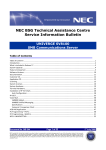
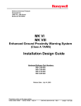
For main software phase 6 and above, use of the Line Key allows
different restriction settings, refer to figures A3-1 and A3-2.
SYSTEM
AVAILABILITY
Terminal Type
All Terminals
Required Components
MIFM-U13
OPERATING
PROCEDURE
To enter a Forced/Verified Account Code from any station:
1.
Lift the handset; receive internal dial tone.
2.
Dial the Forced Account Access Code. A second dial tone is
received. This Access Code is programmable in System
Programming.
3.
Dial the Forced Account Code. Internal dial tone is received.
4.
Dial the Trunk Access code and the outside number.
A6-324000-642-05 – Release 6.0
May 2003
To program Forced/Verified Account Code from Attendant
Position:
1.
Lift the handset; receive internal dial tone.
2.
Dial the Forced Account Access Code (not assigned at default). A
second dial tone is received.
3.
Dial the Forced Account Number (00A ~ E00).
4.
Dial the Forced Account Code (default: 10 digits). Confirmation tone
is received.
5.
Press
to enter the information. The next Account Number is
displayed. (Repeat steps 4 ~ 5 until all desired Account Codes
are entered.)
6.
Press
Features and Specifications Manual
N
P to finish entering Account Codes.
A3 - 15
NEC Business Solutions Ltd
Xen Master and Xen Axis Systems
To use this feature with Scrolling Directories:
1.
Press the V (SYS. or STA softkey) to designate system or station
speed dialling.
2.
Press the V (UP or DOWN softkey) to view the names/numbers
listed in the directory.
– OR –
Press a dial pad key (to select the first letter of the name or number
of the desired speed dial buffer) and dial J.
SERVICE
CONDITIONS
3.
To dial the number press
4.
Enter the Account Code.
P or lift the handset.
Data Assignment
Use Memory Block 1-8-07 [Class of Service (Attendant) Feature
Selection 1] Page 2 LK8 to Allow (default LED On) or Deny (LED off)
Attendant Positions to program Forced Account Codes.
Use Memory Block 1-8-08 [Class of Service (Station) Feature
Selection 2] Page 5 LK1 to Allow (LED On) or Deny (default: LED Off)
Account Code Forced/Verified.
Use Memory Block 1-8-27 (Forced Account Code Length Assignment)
to assign the number of digits for Account Codes system-wide. One to
13 digits can be assigned; default is 10 digits.
A6-324000-642-05 – Release 6.0
May 2003
Use Memory Block 7-1 (Card Interface Slot Assignment) to specify the
necessary MIFM-13 ETU.
A3 - 16
Account Code - Forced/Verified
May 2003
Fig.: A3-1 Account Code Forced/Verified (Version 5.XX and earlier)
Speaker on or off
mode ICM DT
Press Line Key
(Network DT)
Speaker or Off Hook
(ICM DT)
Trunk Access
Code
MB 1-1-46/47/48
Correct F/V
Account Code Access
NO
YES
Correct F/V
Account Code
NO
YES
Error Display
and Tone
ICM (DT)
MB 1-1-46/47/48
Enter trunk Access Code
(Second DT)
Dial Digits
Check against 4-07, 4-08
Dial destination if number allowed.
Fig.: A3-2 Account Code Forced/Verified (Version 6.XX and later)
Press Off Line Key
(Network DT)
Speaker or Off Hook
(ICM DT)
YES
NO
Trunk Access Code
(Trunk Group
Route Advance)
or CO/PBX
MB 1-1-46/47/48
Correct F/V
Account Code Access
YES
NO
Correct F/V
Account Code
YES
Error Displace
and Tone
ICM (DT)
MB 1-1-46/47/48
A6-324000-642-05 – Release 6.0
May 2003
Enter trunk Access Code
(Second DT)
Dial Digits
Dial Digits
Check against 4-07, 4-08
Check against 4-07, 4-08
Dial Digits
Check Agent
4-64, 4-65
Dial destination if number allowed.
Features and Specifications Manual
A3 - 17
NEC Business Solutions Ltd
Xen Master and Xen Axis Systems
Restrictions
Existing restrictions and Least Cost Routing (LCR) assignments are
applied after Forced Account Codes are entered.
000 calls cannot be made unless a valid Forced Account Code is
entered. In such cases, provide access to emergency numbers by
programming them into One-Touch or Feature Access keys.
Verified and Unverified Forced Account Codes cannot be used in the
same class of service.
General
For System Software Version 6.00 and above, an alternate restriction
table for direct trunk access is provided. Refer to Fig.: A3-1 Account
Code Forced/Verified (Version 5.XX and earlier) and Fig.: A3-2
Account Code Forced/Verified (Version 5.XX and earlier), above.
Only outgoing calls from an intercom require a Forced Account Access
Code. Direct access to trunks bypasses this feature.
Reorder tone is provided if an outgoing call is Dialled without entering
the Forced Account Access Code and a valid Forced Account Code.
Call Alert Notification is not provided during Account Code Entry
verification and programming.
PBR Timer values apply when using a Single Line Telephone to enter
a Forced/Verified Account Code.
Forced Account Codes can be uploaded, downloaded, or modified
using PC based System Programming.
Forced Account Code and Account Code entries print on the SMDR
report if both are used.
A is placed in front of the Forced Account Codes on the SMDR reports
to distinguish them from other Account Code entries.
Attendant Positions can be used to program Forced Account Codes
only if allow is assigned in Attendant Class of Service.
The maximum number of Forced Account Codes that can be entered
system-wide is 500.
RELATED
FEATURES LIST
A3 - 18
Feature
Number
Feature Name
A-1
Account Code Entry
A-2
Account Code - Forced/Unverified
S-15
Station Message Detail Recording (SMDR)
Account Code - Forced/Verified
A6-324000-642-05 – Release 6.0
May 2003
System software release 4.0 or later is required for Scrolling Directions
to be used with this feature.
Add-On Conference
FEATURE
DESCRIPTION
A-4
The Add-On Conference feature allows a conference call with a maximum
of four parties with various combinations of outside lines and stations. This
increases efficiency by allowing multiple parties to enter into a conversation.
Up to sixteen 4-party conferences are allowed with no more than two
outside lines per conference.
SYSTEM
AVAILABILITY
Terminal Type
All stations.
Required Components
None.
OPERATING
PROCEDURES
To initiate an Add-On Conference using a Multiline Terminal with a
call in progress:
R.
1.
Press
2.
Dial a station number or outside party, and inform the answering
party of the conference.
3.
Press
4.
Repeat steps 1~3 to add an additional party to the conference.
Ragain. TheRLED lights solid. Talk with both parties.
To initiate an Add-On Conference using a Single Line Telephone
with a call in progress:
1.
Press the hookswitch to place the first call on hold.
2.
Dial an internal station and announce conference.
3.
Press the hookswitch again. Talk with both parties.
A6-324000-642-05 – Release 6.0
May 2003
Refer to Privacy Release, on Page 363 for a different method of
entering conference.
SERVICE
CONDITIONS
Restrictions
A Single Line Telephone cannot be used to originate a 2-party CO
conference.
A Multiline Terminal user that is put on hold cannot enter into another
conference.
Features and Specifications Manual
A4 - 19
NEC Business Solutions Ltd
Xen Master and Xen Axis Systems
General
The elapsed time of the call (from the originating terminal) is shown on
all the Multiline Terminals with a display.
When all sixteen conference circuits are in use, the Conference key
lights solid red on all Multiline Terminals.
Allowed conference configurations are:
• 4 terminals - no outside party
• 3 terminals - 1 outside party
• 3 terminals - no outside party
• 2 terminals - 1 outside party
• 1 terminal - 2 outside parties
Only one member of a conference can place a conference on hold at
a time.
When the conference is placed on hold, the Conference LED flashes
on all phones in the conference.
No recall is provided at the Multiline Terminal when a conference is
on hold.
The CO to CO db loss of conference is 6 db (3 db per CO). This value
does not include the loss already occurring on each CO circuit. A
telephone for conference connection incurs a 10 db loss in volume.
RELATED
FEATURES LIST
Features which can use conference circuits are: Voice Over Split (V-2), Live
Recording (D-6), Barge-In (B-3), Unsupervised Conference (U-4) and Addon Conference.
Feature
Number
Feature Name
Automatic Release
P-8
Privacy Release
A6-324000-642-05 – Release 6.0
May 2003
A-24
A4 - 20
Add-On Conference
All Call Page
A-5
FEATURE
DESCRIPTION
The All Call Page feature allows simultaneous paging (internal and
external) of all idle Multiline Terminals in a zone over their built-in speakers
and over all external paging speakers. This enables a person, away from
their desk but within hearing distance of a Multiline Terminal or external
speaker, to respond to the paging call.
SYSTEM
AVAILABILITY
Terminal Type
All Terminals.
Required Components
None.
OPERATING
PROCEDURES
To originate a page on a Multiline Terminal:
U, if the
1.
Lift the handset, and receive internal dial tone (or press
user is already engaged on a call).
2.
Dial Access Code EI (set as default) for All Call Page.
3.
Page.
To answer a page on a Multiline Terminal:
1.
Go off-hook.
2.
Receive internal dial tone.
3.
Dial Meet-Me Access Code EJ (set as default); the display
changes to show the originator station number.
4.
Talk with All Call Page originator.
A6-324000-642-05 – Release 6.0
May 2003
To originate a page on a Single Line Telephone:
1.
Lift the handset, and receive internal dial tone or press the
hookswitch if the user is already engaged in a call.
2.
Dial Access Code EI (set as default) for All Call Page.
3.
Page.
Features and Specifications Manual
A5 - 21
NEC Business Solutions Ltd
Xen Master and Xen Axis Systems
To answer a page on a Single Line Telephone:
QUICK ACCESS
CODE REFERENCE
SERVICE
CONDITIONS
1.
Lift the handset or press the hookswitch if the user is already
engaged in a call.
2.
Receive dial tone.
3.
Dial Meet-Me Access CodeEJ (set as default).
4.
Talk with All Call Page originator.
Default
Access Code Name
Alphabetic
Designation
59
All Internal/External Zone Paging
N/A
5*
Internal/External Meet-Me
N/A
Data Assignment
Stations can be allowed or denied receiving paging through System
Programming. This includes All Call Page, Internal Zone Paging, and
External Zone Paging. This does not include Internal Emergency All
Call Page.
In System Programming, paging alert tone (Internal and/or External)
can be allowed or denied system-wide. The default assignment is
Receive Paging Alert Tone.
Restrictions
Multiline Terminal users engaged in a handsfree call do not receive All
Call Page or Internal Zone Pages.
Multiline Terminals provided with Off-Hook Voice Announcement
cannot receive All Call Page when already engaged in a call.
Only one All Call Page or Internal Zone Page can be established at a
time. Another page can be originated as soon as the first is abandoned
or answered (by Meet-Me Answer).
Simultaneous zone paging (Internal Zones A, B, and C) can be
established at one time; however, All Internal Zone Paging and Internal
Emergency All Call Page cannot be performed if any other internal
page is in use.
All Call Page can be originated or answered (by Meet-Me Answer)
from internal dial tone.
All Call Page times out using the External Paging Time Out with a
default time of five minutes.
A5 - 22
All Call Page
A6-324000-642-05 – Release 6.0
May 2003
General
May 2003
An outside line can be conferenced with External Page to allow a
conversation to be monitored.
The default Access Code for All Call Page is 59. The default Access
Code for All Call Page Meet-Me code is 5 (Internal/External
Meet Me).
Feature
Number
Feature Name
E-1
Elapsed Call Timer
I-5
Internal Zone Paging (Meet Me)
A6-324000-642-05 – Release 6.0
May 2003
RELATED
FEATURES LIST
Features and Specifications Manual
A5 - 23
NEC Business Solutions Ltd
Xen Master and Xen Axis Systems
A6-324000-642-05 – Release 6.0
May 2003
THIS PAGE INTENTIONALLY LEFT BLANK
A5 - 24
All Call Page
Alphanumeric Display
FEATURE
DESCRIPTION
A-6
DTU-Type Display Multiline Terminals are equipped with a 24-character by
3-line Liquid Crystal Display (LCD). Each ETW-Type Display Multiline
Terminals is equipped with a 16-character by 2-line LCD. These displays
provide information such as: date/time, elapsed call time on outside calls,
digits Dialled, internal calling party number, Customized Message, and
Speed Dial entries.
ETW-Type terminals not available in New Zealand.
SYSTEM
AVAILABILITY
Terminal Type
All Multiline Terminals with a Display.
Required Components
A6-324000-642-05 – Release 6.0
May 2003
None.
Features and Specifications Manual
A6 - 25
NEC Business Solutions Ltd
Display
12:24 AM WED 10
Refer to Display Indications table below.
Location
All Stations
with LCD
Definition
Clock/Calendar
FWD 100 - > [ ]
Set Call Forward - All Calls
ALL FWD CANCLD
Cancel DND/Call Forward - All Calls System-Wide
FWD/DND CANCLD
Originator
Cancel DND/Call Forward - All Calls At Individual
Stations
FWD SET [ ]
Originator
Set Call Forward - All Calls From Forward To Extension
FWD RESET [ ]
Reset Call Forward - All Calls From Forward To
Extension
BUSY 100 -- > [ _ ]
Set Call Forward - Busy
FWD BUSY CANCLD
Cancel Call Forward - Busy
NOANS 100 - > [ ]
Set Call Forward - No Answer
FWD NA CANCLD
Cancel Call Forward - No Answer
FWD BNA - > [ ]
Set Call Forward Busy - No Answer
FWD BNA CNCL
Cancel Call Forward Busy - No Answer
BACK MM/DD HH:MM
Set Customized Message
MESSAGE CLEAR
Cancel Customized Message System-Wide or From
Individual Station
NIGHT MODE SET
Night Mode Switch
NIGHT MODE RESET
Reset Night Mode
NT TENANT
Set Night Mode For Tenant
CALLBACK CANCLD
Cancel Callback System-Wide
FNC LAMP OFF
Reset FNC LED
CURRENT PASSWORD ?
Originator
Telephone Password (1)
NEW PASSWORD ?
Originator
Telephone Password (2)
ENTER PASSWORD
Originator
Set Password (CO/PBX Restriction)
RESTRICT SET
Originator
After Setting Password
CALL DENIED
Originator
Display on Station Outgoing Restricted Telephone
RESTRICT CANCLD
Originator
After Canceling Outgoing Call Restriction
CANCEL TEL ? ? ?
Cancel Restriction on Another Telephone
RLY 0 ON
Relay On
RLY 0 OFF
Relay Off
A6 - 26
Alphanumeric Display
A6-324000-642-05 – Release 6.0
May 2003
LCD DISPLAYS
Xen Master and Xen Axis Systems
May 2003
Display
Location
ALARM AM 00 : 00
Set Alarm For A.M.
ALARM PM 00 : 00
Set Alarm For P.M.
ALL ALARM CANCLD
Cancel Alarm System-Wide
SET TIME REMINDER
Set Timed Alarm for SLT
DND SET
Originator
Set Do Not Disturb
SAVE & REPEAT
Originator
Save and Repeat Number Is Stored
INT ALL PAGE
Originator
Internal All Zone Paging
INT PAGE [ A ]
Group Paging
TENT [ ]
Tenant Paging
SPKR [ A ]
Originator
External Speaker
TRF SET CO =
Set Automatic Tandem Trunk Transfer IN/OUT Trunk
TRF CNCL CO =
Reset Automatic Tandem Trunk Transfer
TRF TO CO =
Set or Confirm Transferred Trunk of Automatic Tandem
Trunk Transfer
TRNS TO N / A
Transferred Trunk Not Assigned
00 : EMPTY
No Speed Dial Number Entered
00 : 0 1 2 3 4 5 6 7 8 9
Speed Dial Number Confirmation
NO SMDR
Station Message Detail Recording Not Available
ERROR
Error Message
BUSY
Busy Message
PRINTER TROUBLE
Printer Problems
SPKR [ A , B , C ]
Originator
External All Paging
LINE IDLE
Originator
Trunk Queuing; CO/PBX Trunk Idle
TRUNK QUE SET
Originator
Trunk Queuing Set
LNR [ # ] / SPD [ ]
A6-324000-642-05 – Release 6.0
May 2003
Definition
Press LNR/SPD Key
TRUNK QUE CANCLD
Originator
Trunk Queue cancelled
RCL : 0 1 , 0 2 , 0 3 , 0 4
Originator
Hold Recall
120 < - [ 1 1 0 ] TRANSF
Destination
Ring Transfer
120 = = [ 1 1 0 ] TRANSF
Automatic Ring Transfer
OVD > [ ]
Barge-In On CO/PBX Line (1)
OVD - > CO [ ]
Barge-In On CO/PBX Line (2)
100 < - TIE LN —
Tie Line Answer
Features and Specifications Manual
A6 - 27
NEC Business Solutions Ltd
Display
Xen Master and Xen Axis Systems
Location
Definition
100 < - DID LN —
DID Answer
DATA ENTRY
Enter Data Via System Programming
STA NUMBER?
Call Pickup Direct Originate
100 _ _ [101]URGENT
Voice Over Split Originate/Receive
01/12147517627
Caller ID Indication
MUSIC SET/RESET
Background Music is On/Off
100
Extension number only to be displayed at idle
NAME
Extension name only to be displayed at idle
10 NAME
Extension No.2 digits with number and name display
100 NAME
Extension No.3 digits with number and name display
1000 NAME
Extension No.4 digits with number and name display
French, Spanish and Japanese characters are also available for some
displayed test.
A6-324000-642-05 – Release 6.0
May 2003
SERVICE
CONDITIONS
A6 - 28
Alphanumeric Display
Ancillary Device Connection
FEATURE
DESCRIPTION
A-7
The Ancillary Device Connection feature allows installation of selected
peripheral (ancillary) devices such as an amplified handset, headset,
Analogue telephone devices, or external speakerphone for use on any
Multiline Terminal. This feature enhances operation for which the peripheral
devices are designed.
DTU-Type Terminals accomplish this by using the APR-UA for Analogue
telephone devices, the HFU-UA for full duplex speakerphone, and the ADAUA for devices like tape recorders. These terminals have a built-in headset
connector.
ETW-Type Terminals accomplish this by using the ADA(1)-WA(SW) Unit for
amplified handset, headset, or external speakerphone.
SYSTEM
AVAILABILITY
Terminal Type
All Multiline Terminals.
Required Components
DTU-type MLT + APR-UA, HFU-UA, or ADA-UA Unit
ETW-type MLT + ADA(1)-WA(SW) Unit
OPERATING
PROCEDURES
SERVICE
CONDITIONS
Vary, depending on the ancillary device connected:
Data Assignment
Use Memory Block 1-1-02 (Hookflash Time Selection) to specify the
loop open time for a hookflash signal sent to the CO/PBX when the
recall key on a Multiline Terminal is pressed.
A6-324000-642-05 – Release 6.0
May 2003
Use Memory Block 1-3-02 (SLT Hookflash Signal Selection) to specify
whether a line is held internally or, if behind a PBX, a hookflash (HF)
signal is sent to the line when a Single Line Telephone user performs a
hookflash.
Use Memory Block 4-24 (SLT Hookflash Assignment) to either hold or
disconnect the trunk for the Single Line Telephone (SLT) hooking
operation.
Use Memory Block 4-39 (APR Ring Mode Assignment) to assign the
APR-UA Unit for NON (No Ring), STA (default: ring Station Number
only) or ALL.
Use Memory Block 4-59 (APR Hookflash Selection) to allow or deny
hookflash on an APR. System Software version 5.0 or higher
is required.
Features and Specifications Manual
A7 - 29
NEC Business Solutions Ltd
Xen Master and Xen Axis Systems
Restrictions
The ADA(2)-WA (GG) Unit must not be installed on to an ETW-Type
Terminal connected to a Xen system.
ETW-Type terminals and ADA(1)-WA(SW) Unit are not available in
New Zealand.
General
The optional devices fit underneath the appropriate terminal.
A6-324000-642-05 – Release 6.0
May 2003
An APR-UA Unit with hookflash enabled follows the same operating
procedures as a Single Line Terminal connected to an SLI(8)U13 ETU.
A7 - 30
Ancillary Device Connection
Answer Hold
A-8
FEATURE
DESCRIPTION
The Answer Hold feature enables a Multiline Terminal user to press the
flashing Answer key to answer an incoming ringing call on a CO line key. If
the Multiline Terminal user is already engaged in a call, the first call is
automatically placed on Non-Exclusive Hold when the second call is
answered. Answer Hold is particularly useful at Attendant Positions or other
central answering positions. Using the Answer key speeds call handling,
while Answer Hold prevents accidental call dropping.
SYSTEM
AVAILABILITY
Terminal Type
All Multiline Terminals.
Required Components
None.
OPERATING
PROCEDURES
To answer calls on a different line key with a call in progress:
O LED flashes.
Press O, and answer the new call (O LED goes off). The
1.
Receive CO/PBX incoming ring. The
2.
original call is put on Hold.
A6-324000-642-05 – Release 6.0
May 2003
SERVICE
CONDITIONS
a.
If the original call was on a Call Appearance Key, the call is
placed on Non-Exclusive Hold on the Call Appearance Key.
b.
If the call was on a line key, the call is placed on
Non-Exclusive Hold on the line key.
3.
Talk with the CO/PBX incoming caller.
4.
to place the current call
If additional calls are received, press
on Hold and connect to the next call. (Refer to a and b above.)
O
Restrictions
The Answer Hold feature does not function for incoming internal calls.
CO/PBX incoming calls not assigned to ring or assigned to other
tenants do not activate the Answer Hold feature.
DID/Tie line and DIT/ANA calls do not activate the Answer
Hold feature.
If all the Call Appearance keys are in use, the next call cannot
be answered.
Features and Specifications Manual
A8 - 31
NEC Business Solutions Ltd
Xen Master and Xen Axis Systems
General
CO/PBX ringing transfer/camp-on calls may be answered.
A6-324000-642-05 – Release 6.0
May 2003
If multiple incoming calls activate the Answer key LED, the LED
continues to flash until all the calls are answered.
A8 - 32
Answer Hold
Answer Key
A-9
FEATURE
DESCRIPTION
Multiline Terminals are equipped with an Answer key and associated LED.
The Answer key LED flashes when the Multiline Terminal user receives an
incoming CO/PBX, Tie/DID transferred, and CO/PBX transferred call
ringing/or not ringing in the same tenant group. When multiple calls are
received, the Answer key is used to pick up calls. The Answer key
continues flashing until the last unanswered call is answered. Press the
Answer key during a call to hold the current call and allow the next call to be
answered.
SYSTEM
AVAILABILITY
Terminal Type
All Multiline Terminals.
Required Components
None.
OPERATING
PROCEDURES
To answer calls using the Answer key:
1.
A6-324000-642-05 – Release 6.0
May 2003
SERVICE
CONDITIONS
Receive CO/PBX incoming ring or flashing MW lamp without
ringing.
LED flashes.
2.
O
Press O. The O LED goes out.
3.
Talk with the CO/PBX incoming calling party.
4.
LED flashes
If additional CO incoming calls are received, the
again. Press
to place the current call on Non-Exclusive Hold
and connect the Multiline Terminal user to the next call.
O
O
a.
If the original call was on a Call Appearance Key, the call is
placed on Non-Exclusive Hold on the Call Appearance Key.
b.
If the call was on a line key, the call is placed on
Non-Exclusive Hold on the line key.
Restrictions
Internal calls, internal transfer/camp-on calls, Secondary Incoming
Extension, Automated Attendant, and Tie/DID calls do not activate the
Answer key LED.
Features and Specifications Manual
A9 - 33
NEC Business Solutions Ltd
Xen Master and Xen Axis Systems
General
The Answer key LED functions for incoming CO/PBX calls, CO/PBX
transfer/camp-on calls, and transferred/camped-on Tie/DID calls.
Incoming CO/PBX ringing calls to other tenants, with the CO/PBX line
appearance and with or without ring assignment, activate the Answer
key LED.
A6-324000-642-05 – Release 6.0
May 2003
Incoming calls answered by the Answer key are handled by first infirst out.
A9 - 34
Answer Key
Assigned Night Answer
(ANA)
FEATURE
DESCRIPTION
A-10
The Assigned Night Answer (ANA) feature is a Direct Inward Termination
programmed to ring directly at a selected station when the system or tenant
is in the Night Mode. This assignment operates independently from the DIT
(Day Mode) ringing assignment.
For main software release 2 and above, the ringing can be delayed up to
30 seconds.
SYSTEM
AVAILABILITY
Terminal Type
All terminals.
Required Components
None.
OPERATING
PROCEDURES
SERVICE
CONDITIONS
Normal incoming call handling procedures apply:
Data Assignment
CO/PBX lines can be assigned to ring a station number, a hunt group
master number, or an ACD/UCD Pilot number.
Multiple CO/PBX lines can be assigned to ring at the same station,
hunt group master number, or ACD/UCD Pilot number.
Incoming ANA calls follow the station Call Forward setting.
Restrictions
When a CO/PBX line is assigned for ANA, the Night Mode CO/PBX
ring assignment is disabled.
General
A6-324000-642-05 – Release 6.0
May 2003
ANA incoming ringing is assigned for Distinctive Ring or Synchronous
Ring system-wide.
When a busy station, programmed for ANA, receives an incoming
ANA call, the system provides Camp-On tone for the busy station. The
calling party receives ringback tone until the call is answered.
A Call Pickup for the same tenant, Access Code 68 (set at default),
can be used to answer ANA calls.
ANA calls do not activate External Tone Ringer or Night Chime.
Features and Specifications Manual
A10 - 35
NEC Business Solutions Ltd
Xen Master and Xen Axis Systems
ANA calls can be assigned to ring on voice mail ports. A hunt group
can be assigned by using the internal master hunt number
assignments.
When a station, programmed for ANA, receives an incoming ANA call,
internal ring tone is heard at all stations where a secondary incoming
extension appeACR and is assigned to ring.
Incoming ANA calls cannot be answered directly at the CO line key
appearance. The CO line key indicates Other Use (red LED).
While receiving an incoming ANA call, an internal call cannot be made.
For main software release 2 and above, the ringing can be delayed for
0, 5, 10, 20, 30, 40, 50, 60 seconds.
RELATED
FEATURES LIST
Feature
Number
Direct Inward Termination (DIT)
A6-324000-642-05 – Release 6.0
May 2003
D-10
Feature Name
A10 - 36
Assigned Night Answer (ANA)
Attendant Add-On Console
A-11
FEATURE
DESCRIPTION
The Attendant Add-On Console functions in conjunction with a Multiline
Terminal programmed as an Attendant. This console provides access to a
maximum of 48 stations and/or outside lines. The Busy Lamp Field status is
shown as a red LED for each station or trunk. Trunks can include CO/PBX,
ISDN, DID and E&M Tie Lines. In addition, the Attendant Add-On Console
also has 12 function keys that can be used for attendant messaging, paging
access, or other undefined functions.
SYSTEM
AVAILABILITY
Terminal Type
Any terminal programmed as an Attendant Position.
Required Components
DCU-60-1(WH) or EDW-48-2(SW) DSS/BLF.
EDW-48-(SW) DSS/BLF is not available in New Zealand.
OPERATING
PROCEDURES
To transfer a call:
1.
Attendant answers an incoming CO/PBX call.
2.
Press the DSS/BLF key for the desired station. The calling party is
put on Non-Exclusive Hold.
3.
When the called party answers the Attendant call, the Attendant
announces the call and then presses
On Console.
4.
N on the Attendant Add-
Go on-hook.
- OR -
A6-324000-642-05 – Release 6.0
May 2003
Attendant answers an incoming CO/PBX call.
5.
Press the Attendant Add-On Console key for the desired station.
The calling party is put on Non-Exclusive Hold.
6.
Press
7.
Go on-hook.
Features and Specifications Manual
N on the Add-On Console.
A11 - 37
NEC Business Solutions Ltd
Xen Master and Xen Axis Systems
To call a station:
1.
Lift the handset and receive internal dial tone.
2.
Press the DSS/BLF key for the desired station. Hear ringback tone
or voice announce the station.
3.
Called party answers.
To set/cancel Message Waiting or Station Outgoing Lockout
(Outgoing Restrict) to station:
1.
Press the Message Wait or Station Lockout key.
2.
Press the DSS/BLF key for the desired station.
To make an outgoing call using the Attendant Add-On Console
from the Attendant Position:
1.
Go off-hook with the handset or just press a CO line key on the
Attendant Add-On Console.
2.
Dial the desired number.
To answer an incoming call using the Attendant Add-On Console
from the Attendant Position
Press the incoming CO line key or flashing
SERVICE
CONDITIONS
O if ringing is assigned.
Data Assignment
Additional attendant-type features can be allowed or denied in the
Class of Service (Attendant) Feature Selection.
Restrictions
A maximum of four DCU-60-1(WH) or EDW-48-2(SW) Consoles can
be installed per system.
A maximum of four Attendant Add-On Consoles can be connected to
one station.
General
Both DSS/BLF for stations and CO lines can appear on the same
DCU-60-1(WH) or EDW-48-2(SW) Consoles.
Depending on System Programming (DSS Call Voice/Tone Signal
Selection), the called party rings or receives a voice announcement
when an Attendant makes a call using the Attendant Add-On Console.
When the Attendant transfers a call, the transferred outside line
remains on Non-Exclusive Hold until the call is answered.
A11 - 38
Attendant Add-On Console
A6-324000-642-05 – Release 6.0
May 2003
The 48 DSS keys and 12 function keys on Attendant Add-On Consoles
are flexible and can be changed.
May 2003
Each installed Attendant Add-On Console reduces the maximum
number of stations by one.
The keys are assigned at default as follows:
Keys
01~48
49
50~53
ICM Call
Night Mode
Direct Paging Access
54
Vacant
55
Message
56~59
60
Stations 100-147 (depending
on system configuration)
Internal Zone and All Zone
Page
External All Zoone
Paging
External Zone and All Zone
Page
Transfer
o
Busy Lamp Field indications show if Multiline Terminals, outside lines,
or zone paging is in use.
Busy Lamp Field status indications at the Attendant Add-On
Console are:
LED Indications
Busy Lamp Field Status
Off
Station Idle
Green
Not Used
Red
Busy
Flashing
DND, Call Forward - All Calls, Break Mode
(by ACD Agent)
Winking
Function Programming Mode
A6-324000-642-05 – Release 6.0
May 2003
LED Indications
Features and Specifications Manual
Outside Line Status
Off
Outside Line Idle
Green
In Use (by Attendant station)
Red
Busy
Winking
Call On Hold
Flashing
Incoming Call
A11 - 39
NEC Business Solutions Ltd
Xen Master and Xen Axis Systems
Message Waiting/Station Outgoing Lockout status indications at the
Attendant Add-On Console are:
LED Indications
Station Status
Off
No Message/Lockout Not Set
Green
Message Waiting/Lockout Set
The Attendant, with an Attendant Add-On Console, can set a message
to a Single Line Telephone if the Single Line Telephone is equipped
with a Message Waiting LED and connected to a SLI(8)-U13 ETU.
When the Message Waiting indication is set, the Large LED flashes
green on Multiline Terminals and continues to flash until the message
is cancelled by an Attendant.
Attendant Add-On Consoles can be assigned to any Multiline Terminal
programmed as an Attendant Position.
When the entire system is switched into the Night Mode, the Night
Transfer (NT) key LED on the Attendant Add-On Console lights red.
An Attendant Add-On Console cannot have a Message Wait key and a
Station Lockout key assigned at the same time.
If multiple CO calls are ringing at an Attendant Station or Attendant
Add-On Console, the calls are answered in first in-first out order.
Feature
Number
Feature Name
A-13
Attendant Positions
A-14
Attendant Station Outgoing Lockout
B-1
Background Music Over External Speakers
M-1
Message Waiting
A6-324000-642-05 – Release 6.0
May 2003
RELATED
FEATURES LIST
A11 - 40
Attendant Add-On Console
Attendant Camp-On
A-12
FEATURE
DESCRIPTION
The Attendant Camp-On feature, used at an Attendant Position with an
Attendant Add-On Console, allows a call to be transferred to a busy station.
Press the Transfer key on the Attendant Add-On Console to send the
Camp-On tone to the busy station. A camped on call that is not answered in
a preprogrammed time recalls to the Attendant Position.
SYSTEM
AVAILABILITY
Terminal Type
Any terminal with Display programmed as an Attendant Position.
Required Components
DCU-60-1(WH) or EDW-48-2(SW) DSS/BLF.
EDW-48-2(SW) DSS/BLF is not available in New Zealand.
OPERATING
PROCEDURES
To use this feature at an Attendant Position with a CO/PBX Call in
progress:
1.
Press the DSS/BLF key on the Attendant Add-On Console or the
Attendant Position for the desired station.
2.
Receive call waiting tone.
3.
on the Attendant Add-On Console or on the Attendant
Press
Position. Camp-On is set.
4.
Go on hook.
5.
After time-out, if the Camp-On is not answered, a recall tone is
received at the Attendant Position, and the LED on the assigned
CO/PBX line key or Call Appearance Key returns to flashing green.
6.
Press the CO/PBX line key with the flashing green LED to return to
the call.
N
A6-324000-642-05 – Release 6.0
May 2003
To answer a Camp-On Call from a Multiline Terminal:
1.
The user is engaged in a call.
2.
Receive a camp-on tone. The
flashes red, the Large LED
flashes green, and CO/PBX line flashes green, if assigned.
3.
Press
O
O and talk with the CO/PBX incoming caller. The previous
call is put on hold.
Features and Specifications Manual
A12 - 41
NEC Business Solutions Ltd
Xen Master and Xen Axis Systems
To answer a Camp-On Call from a Single Line Telephone:
SERVICE
CONDITIONS
1.
The user is engaged in a call.
2.
Receive a camp-on tone.
3.
Hang up or put the call on System Call Park.
4.
Go off-hook, and talk with the CO/PBX incoming caller.
Data Assignment
This feature is allowed only if the system is programmed for Ring
Transfer.
The Attendant Camp-On Recall Timer can be set for 30 seconds, 1,
1.5, 2, 3, 5, 8, or 10 minutes (default:1 minute).
In Class of Service (station) assignments, stations can be assigned not
to receive an Attendant Camp-On tone.
Restrictions
Camp-On is not allowed to stations that have received Tone Override.
General
The camp-on tone is heard over the handset or from the speaker if the
Multiline Terminal is in the handsfree mode.
Any number of outside calls can be camped on to a station. When the
station goes idle, the Camp-On calls are answered in order from the
lowest numbered lines to the highest numbered lines.
Two types of Camp-On are provided by the system
• Attendant Camp-On
• Station Camp-On.
Feature
Number
Feature Name
C-16
Class of Service
D-14
Do Not Disturb (DND)
S-12
Speed Dial - System
A6-324000-642-05 – Release 6.0
May 2003
RELATED FEATURES
LIST
A12 - 42
Attendant Camp-On
Attendant Positions
A-13
FEATURE
DESCRIPTION
Any number of stations can be designated an Attendant Position. These
stations have access to distinct Attendant-type features; up to four
attendants can support Attendant Add-On Consoles. Attendant features
such as setting Night Mode and System Speed Dial memory
programming apply.
SYSTEM
AVAILABILITY
Terminal Type
Any terminal with Display programmed as an Attendant Position.
Required Components
None.
OPERATING
PROCEDURES
SERVICE
CONDITIONS
Provided under specific Attendant feature descriptions:
Data Assignment
The first two station ports, 01 and 02, are assigned as Attendant
Positions by Resident System Programming.
Attendant features can be assigned to any station via station Class
of Service.
Restrictions
A maximum of four Attendant Add-On Consoles can be assigned to
one Attendant Position.
A maximum of four Attendant Add-On Consoles can be assigned in
the system.
A6-324000-642-05 – Release 6.0
May 2003
Up to four Attendant positions can have an Attendant Add-on Console.
Features and Specifications Manual
A13 - 43
NEC Business Solutions Ltd
Feature
Number
Feature Name
A-17
Automated Attendant
C-1
Call Alert Notification
C-7
Caller ID - Outgoing
D-14
Do Not Disturb (DND)
N-4
Night TransferNight Transfer
S-8
SLT Timed Alarm
S-12
Speed Dial - System
S-18
Station Relocation
A6-324000-642-05 – Release 6.0
May 2003
RELATED FEATURES
LIST
Xen Master and Xen Axis Systems
A13 - 44
Attendant Positions
Attendant Station
Outgoing Lockout
A-14
FEATURE
DESCRIPTION
The Attendant Station Outgoing Lockout feature allows an Attendant
Position with an Attendant Add-On Console to set a predetermined Code
Restriction Class Assignment to any station that is assigned on the
Attendant Add-On Console. This allows an Attendant to set/reset
restrictions to disallow outgoing calls.
SYSTEM
AVAILABILITY
Terminal Type
Any Display terminal programmed as an Attendant Position.
Required Components
DCU-60-1(WH) or EDW-48-2(SW) DSS/BLF.
EDW-48-2(SW) DSS/BLF is not available in New Zealand.
OPERATING
PROCEDURES
To set the Attendant Station Outgoing Lockout from the Attendant
Position using the Attendant Add-On Console:
1.
Press the key programmed as Lockout key on the Attendant AddOn Console.
2.
Press the DSS key on the Attendant Add-On Console that is
associated with the station where Attendant Station Outgoing
Lockout is desired.
3.
The green LED lights next to the DSS key to indicate lockout is set.
A6-324000-642-05 – Release 6.0
May 2003
To cancel the Attendant Station Outgoing Lockout from the
Attendant Position using the Attendant Add-On Console:
1.
Press the key programmed as Lockout key on the Attendant AddOn Console.
2.
Press the DSS key on the Attendant Add-On Console that is
associated with the station where Attendant Station Outgoing
Lockout is to be cancelled.
3.
The green LED next to the DSS key turns off to indicate the lockout
is cancelled.
Features and Specifications Manual
A14 - 45
NEC Business Solutions Ltd
SERVICE
CONDITIONS
Xen Master and Xen Axis Systems
Data Assignment
At default, when a station with Attendant Station Outgoing Lockout is
set, the station is outgoing restricted. This can be changed
(system-wide) to a different Code Restriction Class in
System Programming.
When up to four Attendant Add-On Consoles are installed, the
Attendant Station Outgoing Lockout is displayed only on the Attendant
Add-On Console from where the Lockout was set.
Restrictions
An Attendant Add-On Console, with an Attendant Station Outgoing
Lockout key assigned on it, cannot be used to set the Message
Waiting feature from an Attendant.
General
All Attendant Add-On Consoles can be used to set Attendant Station
Outgoing Lockout.
Attendant Station Outgoing Lockout is retained by the memory
backup battery.
No indication is provided at a terminal when Attendant Station
Outgoing Lockout is set.
To confirm that Attendant Station Outgoing Lockout is set at an
Attendant Add-On Console, ensure that the green LED associated
with the station is lit. Lockout remains set until cancelled at the
Attendant Add-On Console where it was set.
The station with Attendant Station Outgoing Lockout set cannot
manually cancel the lockout.
Feature
Number
Feature Name
M-1
Message Waiting
S-17
Station Outgoing Lockout
A6-324000-642-05 – Release 6.0
May 2003
RELATED
FEATURES LIST
A14 - 46
Attendant Station Outgoing Lockout
Attendant Transfer
A-15
FEATURE
DESCRIPTION
The Attendant Transfer feature permits efficient call transfers in the system
using an Attendant Multiline Terminal equipped with one to four Attendant
Add-On Console(s). Transferred calls can be voice announced, ring
transferred, or camped on (if the station is busy). All unanswered
transferred calls return to the Attendant with distinct audible and visual
indications, after a programmed time interval.
SYSTEM
AVAILABILITY
Terminal Type
Any terminal with Display programmed as an Attendant Position.
Required Components
DCU-60-1(WH) or EDW-48-2(SW) DSS/BLF.
EDW-48-2(SW) DSS/BLF is not available in New Zealand.
OPERATING
PROCEDURES
To use this feature at the Attendant Position with a CO/PBX call in
progress:
1.
Press the DSS key on the Attendant Add-On Console or the
Attendant Position for the desired station.
2.
Receive ringback tone or voice announcement.
3.
Press
N on the Attendant Add-On Console or on the Attendant
A6-324000-642-05 – Release 6.0
May 2003
Position. The call is transferred.
SERVICE
CONDITIONS
4.
Hang up.
5.
After time-out, if the transferred call is not answered, a recall tone is
received at the Attendant Position; and the LED on the assigned
CO/PBX line key or Call Appearance Key returns to flashing green.
6.
Press the CO/PBX line key with the flashing green LED to return to
the call.
Data Assignment
The Attendant Transfer/Camp-On recall time-out is programmable
(default: 60 seconds).
CO Transfer Ring Pattern and Ring Tone can be assigned in System
Programming.
Features and Specifications Manual
A15 - 47
NEC Business Solutions Ltd
Xen Master and Xen Axis Systems
General
When a Transfer/Camp-On is denied, the call remains on hold at the
Attendant Position Multiline Terminal.
The outside line key LED flashes green on the station receiving the
Transfer/Camp-On, if the line appeACR on that station. The Large LED
also flashes green and the LED or the ANS key flashes red.
An Attendant trying to Transfer/Camp-On a call to a station may be
denied, if the Multiline Terminal is busy and receiving Tone Override.
Feature
Number
Feature Name
A-11
Attendant Add-On Console
A-12
Attendant Camp-On
A-24
Automatic Release
A6-324000-642-05 – Release 6.0
May 2003
RELATED
FEATURES LIST
A15 - 48
Attendant Transfer
Automatic Answer with
Delay Message
A-16
FEATURE
DESCRIPTION
The Automatic Answer with Delay Message feature answers incoming CO/
PBX calls and plays a specified message to the outside caller while still
ringing designated stations. Up to two messages can be played to the
outside caller. The message(s) played are the same as the Automated
Attendant message(s).
SYSTEM
AVAILABILITY
Terminal Type
Not applicable.
Required Components
VRS(4)-U13 ETU
OPERATING
PROCEDURES
To record an Automated Attendant Message:
1.
Go off-hook.
2.
Dial the VRS Voice Message Record/Verify/Erase Access Code
(e.g. E0).
3.
Dial operation:
A = Recording
B = Confirmation
C = Erasing
4.
Dial operation:
A = Automated Attendant
5.
Enter Automated Attendant Message (A~H).
6.
Enter Mode:
A= Day Mode
A6-324000-642-05 – Release 6.0
May 2003
B = Night Mode
7.
Record Message.
8.
Go on-hook.
Features and Specifications Manual
A16 - 49
NEC Business Solutions Ltd
Xen Master and Xen Axis Systems
To set the Automated Attendant/Delay Message Mode from the
Attendant Position:
T.
1.
Press
2.
Dial HA.
3.
Dial the incoming trunk number (00~FD). [00 = All
CO/PBX lines].
Dialling 00 sets or cancels the Automated Attendant mode for all
trunks when the trunks are idle. If a trunk is busy when 00 is dialled, it
is not set. To set the Automated Attendant to a busy trunk, dial the
individual trunk number.
4.
T.
Press
To cancel the Automated Attendant/Delay Message Mode from the
Attendant Position:
T.
1.
Press
2.
Dial HB.
3.
Dial the incoming trunk number (00~FD). [00 = All
CO/PBX lines].
Dialling 00 sets or cancels the Automated Attendant mode for all
trunks when the trunks are idle. If a trunk is busy when 00 is dialled, it
is not set. To set the Automated Attendant to a busy trunk, dial the
individual trunk number.
4.
T.
Press
To answer by One Level:
1.
Receive an incoming CO/PBX call.
2.
The Automatic Answer with Delay Message answers the call and
sends a greeting.
3.
The outside party heACR ringback tone or MOH (System
Programmable).
A16 - 50
1.
Receive an incoming CO/PBX call.
2.
The Automatic Answer with Delay Message answers the call and
sends a greeting.
3.
The outside party heACR ringback tone or MOH (System
Programmable).
4.
After the time expires, a second message is played.
5.
The outside party heACR ringback tone or MOH until the call is
answered.
Automatic Answer with Delay Message
A6-324000-642-05 – Release 6.0
May 2003
To answer by Two Levels:
May 2003
SERVICE
CONDITIONS
Data Assignment
A maximum of eight VRS(4)-U13 ETU channels, four channels per
VRS(4)-U13 ETU, can be used for Automated Attendant.
Each channel has 240 recording seconds that can be subdivided into
2, 4, 8 or 16 equal recording times.
A maximum of eight Automated Attendants can be assigned.
Automated Attendant can be assigned per CO/PBX line. Attendant
Positions can set or cancel the Automated Attendant per trunk.
The Day/Night Weekend mode greeting messages can be assigned to
each Automated Attendant position. The number of times a greeting
message is repeated can be assigned in System Programming.
The answering time (duration after the incoming CO/PBX call rings) is
programmable. This time affects the Day/Night/Weekend mode
settings per Automated Attendant.
The station can be used for recording, confirming, or deleting an
Automated Attendant message if it is allowed by Station Class of
Service assignment in System Programming.
Restrictions
Tie/DID lines are not supported by the Automatic Answer with Delay
Message feature.
DTMF digits cannot be dialled by the outside caller while in the
Automatic Answer with Delay Message mode.
CPUB( )-U13 ETU/MBD-U13 Unit PBR circuits are not used for
this feature.
Automatic Answer with Delay Message or Automated Attendant is
assigned per trunk.
Automatic Trunk-to-Trunk Transfer and the Automated Attendant
features cannot be set for the same trunk at the same time.
General
The Automatic Answer with Delay Message features uses the
Automated Attendant Message to play to the outside caller.
DIT/ANA assigned to the same trunk has higher priority.
A6-324000-642-05 – Release 6.0
May 2003
Automated Attendant and system Access Codes can be assigned
individually.
Automated Attendant assignment is assigned to tenants and follows
the tenants Day/Night/Weekend mode switching.
If Automated Attendant answer is assigned for a trunk and a VRS(4)U13 ETU is not installed, a second dial tone is provided for
incoming callers.
Features and Specifications Manual
A16 - 51
NEC Business Solutions Ltd
RELATED
FEATURES LIST
Xen Master and Xen Axis Systems
Feature
Number
Direct Inward System Access (DISA)
A6-324000-642-05 – Release 6.0
May 2003
D-9
Feature Name
A16 - 52
Automatic Answer with Delay Message
Automated Attendant
FEATURE
DESCRIPTION
A-17
The Automated Attendant answers incoming CO/PBX calls and sends a
greeting message for calling parties. When the caller enters a station
number or a 1- or 2-digit number from the dial pad, as instructed in the
greeting message, the Automated Attendant then transfers the call to a
designated station or Station Hunt group. The Automated Attendant can be
set to provide two automated answering levels.
Incoming DID calls can be answered by the Automated Attendant (system
software version 4.0 or higher is required).
SYSTEM
AVAILABILITY
Terminal Type
Not applicable.
Required Components
VRS(4)-U13 ETU
OPERATING
PROCEDURES
To record an Automated Attendant Message:
1.
Go off-hook.
2.
Dial the VRS Voice Message Record/Verify/Erase Access Code
(e.g., E0).
3.
Dial operation:
A = Recording
B = Confirmation
C = Erasing
4.
Dial operation:
A6-324000-642-05 – Release 6.0
May 2003
A = Automated Attendant
B= Voice Prompt Message
C = Delay Announcement
5.
Enter Automated Attendant Message (A~H).
6.
Enter Mode:
A= Day Mode
B = Night Mode
C= Weekend Mode
7.
Record Message.
8.
Go on-hook.
Features and Specifications Manual
A17 - 53
NEC Business Solutions Ltd
Xen Master and Xen Axis Systems
To set the Automated Attendant Mode from the Attendant Position:
T.
1.
Press
2.
Dial HA.
3.
Dial the incoming trunk number (00~FD). [00 = All
CO/PBX lines.]
4.
Dialling 00 sets or cancels the Automated Attendant mode for all
trunks when the trunks are idle. If a trunk is busy when 00 is Dialled,
it is not set. To set the Automated Attendant to a busy trunk, dial the
individual trunk number.
5.
Press
T.
To cancel the Automated Attendant Mode from the Attendant
Position:
T.
1.
Press
2.
Dial HB.
3.
Dial the incoming trunk number (00~FD). [00 = All
CO/PBX lines.]
Dialling 00 sets or cancels the Automated Attendant mode for all
trunks when the trunks are idle. If a trunk is busy when 00 is Dialled, it
is not set. To set the Automated Attendant to a busy trunk, dial the
individual trunk number.
4.
T.
Press
To set/cancel the Weekend Mode from the Attendant Position:
T.
1.
Press
2.
Dial HF.
3.
Dial tenant number (00~DG).
Dialling 00 sets or cancels the Automated Attendant mode for all
trunks when the trunks are idle. If a trunk is busy when 00 is Dialled, it
is not set. To set the Automated Attendant to a busy trunk, dial the
individual trunk number.
4.
T.
Press
A17 - 54
1.
Receive an incoming CO/PBX call.
2.
The Automated Attendant answers the call and sends a greeting.
3.
A DTMF tone is received. (Each tone is assigned to a station
number or a station hunt group.)
4.
The call is transferred to a designated station or station hunt group.
5.
The called party answers and talks.
Automated Attendant
A6-324000-642-05 – Release 6.0
May 2003
To answer by One Level:
May 2003
To answer by Multiple Levels (up to eight levels are available):
1.
Receive an incoming CO/PBX call.
2.
The Automated Attendant answers the call and sends a greeting.
3.
A 1-digit DTMF tone is received. (Each tone is assigned to another
message on the VRS ETU).
4.
The call is answered by the VRS ETU and another message
is played.
5.
A 1-, 2-, or 3-digit DTMF signal is received.
6.
The call is transferred to a designated station of the second level, or
another VRS ETU message is played.
7.
The called party answers and talks.
Timeout - No Answer :
SERVICE
CONDITIONS
1.
An incoming CO/PBX call is received on a line.
2.
The Automated Attendant answers the call and sends a greeting.
3.
A 1-digit DTMF tone is received.
4.
The call is transferred to a designated station or Station Hunt group.
5.
If there is no answer, the CO/PBX ringing transfer at the station is
changed to an ordinary CO/PBX ringing call on the CO/PBX line,
after a predetermined time.
6.
The calling party on the CO/PBX line is answered.
Data Assignment
A maximum of two VRS(4)-U13 ETU’s, four channels per card, can be
used for Automated Attendant.
Each channel has 240 recording seconds that can be subdivided into
2, 4, 8, or 16 equal recording times.
A6-324000-642-05 – Release 6.0
May 2003
A maximum of eight Automated Attendants can be assigned. Multiple
Automated Attendants can be assigned to one VRS(4)-U13
ETU channel.
Use Memory Block 1-4-08 (Automated Attendant PBR Timeout
Response Selection) to specify how a call is answered by the
Automated Attendant if DTMF tone is not received. If NORMAL Call is
specified (default), the system rings selected stations using Memory
Block 4-01[CO/PBX Ring Assignment (Day Mode)] or 4-02 [CO/PBX
Ring Assignment (Night Mode)]. When RELEAS is specified, the call is
dropped after a fixed time of 30 seconds.
Use Memory Block 1-4-09 (Automated Attendant PBR Start Time
Selection) to specify whether the PBR can receive DTMF signaling
while the Automated Attendant is sending the message (default: FR)
or after the message is finished (AF).
Features and Specifications Manual
A17 - 55
NEC Business Solutions Ltd
Xen Master and Xen Axis Systems
Use Memory Block 1-4-11 (Automated Attendant Message Day/Night
Mode Selection) to assign the Day/Night/Weekend mode greeting
messages to each Automated Attendant position.
Use Memory Block 1-4-13 (Automated Attendant Answer Delay Time
Assignment) to set the answering time (default: 4 seconds) between
when the incoming CO/PBX call rings and when it is answered. This
time affects the Day/Night/Weekend mode settings per Automated
Attendant.
Use Memory Block 1-4-16 (Automated Attendant Message Repeat
Selection) to assign the number of times a greeting message is
repeated (default: 1).
Use Memory Block 1-4-21 (Automated Attendant Extensions Number
Assignment) to specify the message that is played when a DID call is
received. System software release 4.0 or higher is required.
Use Memory Block 1-4-22 (Automated Attendant Direct Extension
Ring Assignment) to direct an AA Call to an extension or CAR Key
once the AA PBR timer has expired. Calls cannot be directed to a CAR
Key if 2 digit extension numbers are used.
Use Memory Block 1-8-07 [Class 0f Service (Attendant) Feature
Selection 1] Page 1 LK8 to Allow (default: LED On) or Deny (LED Off)
Attendant Positions to set/reset the Automated Attendant per trunk.
Use Memory Block 1-8-08 [Class 0f Service (Station) Feature
Selection 2] Page 2 LK6 to Allow (default: LED On) or Deny (LED Off)
a station to record, verify, or erase an Automated Attendant message.
Use Memory Block 3-05 (Trunk Incoming Answer Mode Selection) to
assign Automated Attendant per CO/PBX line.
Use Memory Block 3-65 (Hold Tone Automated Attendant Selection) to
specify the message to be played to an extension or DID trunk on an
incoming call. System software release 4.0 or higher is required.
Use Memory Block 4-58 (Automated Attendant Selection for DID) to
specify the message for DID calls. System software release 4.0 or
higher is required.
Use Memory Block 7-1 (Card Interface Slot Assignment) to specify the
VRS(4)-U13 ETU.
CPU-based PBR circuits are required and used for this feature. The
CPUB-U13 ETU of the Xen Master system or MBD-U13 Unit in the
B48-U13 KSU of the Xen Axis system has four built-in PBR circuits
that are programmable for use with the Automated Attendant, DISA
feature, or Single Line Telephones. If all four circuits are programmed
for AA/DISA use, then a PBR( )-U13 ETU must be installed for Single
Line Telephone use.
A17 - 56
Automated Attendant
A6-324000-642-05 – Release 6.0
May 2003
Restrictions
Tie/DID lines are not supported by the Automated Attendant feature.
May 2003
Automatic Trunk-to-Trunk Transfer and the Automated Attendant
features cannot be set for the same trunk at the same time.
General
If the VRS(4)-U13 ETU or PBR is busy and there is an incoming CO/
PBX call, the caller hears a ringback tone until a VRS channel and
PBR are available. (Applicable to DID calls for release 4.0 software
and above.)
If Automated Attendant or PBR is busy, after the call is transferred to
the second level, a ringback tone is sent to the calling party.
DIT/ANA assigned to the same trunk has higher priority.
Automated Attendant and system Access Codes can be assigned
individually.
Automated Attendant assignment is assigned to tenants and follows
the tenants Day/Night/Weekend mode switching.
If Automated Attendant answer is assigned for a trunk and a
VRS(4)-U13 ETU is not installed, second dial tone is provided for
incoming callers.
If an incoming caller is transferred to a busy station, the following
options are available to this caller:
Dial
Action
A
Step Call is performed
J
Second dial tone is provided
L
Ringing begins based on the Day/Night ringing
assignment
A6-324000-642-05 – Release 6.0
May 2003
After recording a new Automated Attendant message, verify its
operation by placing a call into the system and ensuring complete and
correct playback. If you find that the message is ending prematurely or
is automatically triggering the digit entry process, re-record the
message using a different person with a lower pitched voice
if possible.
Using system software version 4.0 or higher, Memory Block 1-4-02
(Automated Attendant Transfer Delayed Ringing Time Selection) is
not required to time out before incoming DID calls can be answered by
the Automated Attendant (can be set to No Limit).
RELATED
FEATURES LIST
Feature
Number
D-9
Features and Specifications Manual
Feature Name
Direct Inward System Access (DISA)
A17 - 57
NEC Business Solutions Ltd
Xen Master and Xen Axis Systems
A6-324000-642-05 – Release 6.0
May 2003
THIS PAGE INTENTIONALLY LEFT BLANK
A17 - 58
Automated Attendant
Automatic Callback
A-18
FEATURE
DESCRIPTION
After receiving a call waiting tone from a busy station, a user can set an
Automatic Callback. When both stations are idle, the system signals the
Automatic Callback originator first and, after answered, signals the
other station.
SYSTEM
AVAILABILITY
Terminal Type
All terminals.
Required Components
None.
OPERATING
PROCEDURES
SERVICE
CONDITIONS
To use this feature after calling a busy station and receiving a call
waiting tone:
1.
Dial Access Code 0 (set as default).
2.
Hang up.
3.
The originating station rings when both stations become idle.
4.
Lift the handset or press
5.
Receive tone burst or ringback tone; talk when the called station
user answers.
P.
Data Assignment
The Access Code can be changed to one of the following: , #, or 1~9.
Restrictions
Only one Automatic Callback at a time may be set at a station.
Automatic Callback cannot be set to a station that is in Do Not
Disturb mode.
A6-324000-642-05 – Release 6.0
May 2003
Call Pickup Group feature does not pickup Automatic Callback ringing
on the originator station.
Automatic Callback setting is automatically cancelled unless both
stations become idle within 30 minutes (set as default).
Features and Specifications Manual
A18 - 59
NEC Business Solutions Ltd
Xen Master and Xen Axis Systems
General
Any station can be used for setting an Automatic Callback. An
Automatic Callback can be set to multiple stations regardless
of tenants.
If the user that set an Automatic Callback receives the Callback and
does not answer within 30 seconds after the ringing begins, the
Callback is automatically released.
A6-324000-642-05 – Release 6.0
May 2003
While set, a Callback cannot be manually cancelled.
A18 - 60
Automatic Callback
Automatic Call
Distribution (ACD)
A-19
FEATURE
DESCRIPTION
The Automatic Call Distribution (ACD) feature permits any incoming calls
(DIT, ANA, DID, and CO Ring Transfer) to a prearranged ACD Group of
Agents. An incoming call is distributed to the Agent of the ACD Group that
has been idle the longest. The ACD feature has four distinct parts: Call
Distribution, Agents and Supervisor Function, Status screens and
Management Information System (MIS) reports, and Delay Announcement.
This feature is not available on the Xen Axis system.
SYSTEM
AVAILABILITY
Terminal Type
All terminals.
Required Components
MIFA-U13 ETU
KMA(XXX)-UA for ACD
VRS(4)-U13 ETU for Delay Announcement.
OPERATING
PROCEDURES
Refer to the Automatic Call Distribution Manual:
CALL PROCESSING
GENERAL
DESCRIPTION
This section includes the following features:
Abandoned Call Search
Abandoned incoming calls are not connected to Agent Positions. The
system can recognize abandoned calls and remove them from the queue
on trunks that provide calling party disconnect supervision.
A6-324000-642-05 – Release 6.0
May 2003
Call Distribution to Agents
Calls are automatically distributed in a uniform manner among Agents in an
ACD Group. Calls are distributed to the longest idle Agent Position. When
incoming calls are holding, the oldest call is connected to the first available
Agent position.
Call Transfer to ACD Group Queue
CO Trunk calls that have terminated to either a normal station, ACD Agent,
or Supervisor Position may be transferred to an ACD group queue.
Features and Specifications Manual
A19 - 61
NEC Business Solutions Ltd
Xen Master and Xen Axis Systems
Night Service
When the ACD group is placed in Night Mode, the system can route all
incoming ACD calls to one of the following: Internal Station, Night
Announcement, transfer to the Attendant, or Trunk-to-Trunk Transfer.
Overflow
Overflow Service allows calls held in queue for more than a predetermined
time to be directed to an assigned station or Station Hunt group, but not to
overflow to another group.
Queuing
All incoming calls destined for ACD groups are placed in queue when no
Agent in the ACD group is presently available to handle the call. Queue is
used to provide service in order of arrival (first in-first out).
Pilot Numbers
Pilot numbers are the Access Codes to ACD functions. They are
programmed into the System Data according to the numbering plan in effect
for the system. Pilot numbers do not correspond to any line appearances in
the Xen systems. No hardware equipment is required to assign a Pilot
number. An ACD Group Pilot number should not be programmed in a
Station Hunt group. The Station Hunt feature takes priority over the ACD
function.
SERVICE
CONDITIONS
Data assignment
Restrictions
No alert tone is provided even if all Agents in the ACD group are busy.
However, Pooled Line (Outgoing) can indicate the status of trunks in
an ACD group as an alternative method.
General
If the Agent (in the ACD group where a call is terminated) does not
answer for a predetermined time, the call is transferred to another
Agent in the ACD group.
If the Agents (in the ACD group where a call is terminated) are all busy,
the call waits in a queue until an Agent is available. The caller receives
a Delay Announcement and Music On Hold. Calls are answered firstin, first-out.
When an incoming call to an ACD group encounters all ACD Agents
busy or no answer, the call is queued and the caller receives a
recorded
announcement
(Delay
Announcement)
after
a
predetermined time.
The ACD group is assigned a Pilot number. Calls directed to the Pilot
number are directed to Agents of that ACD group.
A19 - 62
Automatic Call Distribution (ACD)
A6-324000-642-05 – Release 6.0
May 2003
When the overflow destination station is busy, calls continue searching
the ACD group for an available Agent.
May 2003
The following maximum assignments for programming ACD groups
and Agents are:
• Up to 32 Agents can be programmed per system.
• Up to four ACD Groups can be assigned per system.
Up to 32 Agents can be assigned in one ACD group.
All trunks used for ACD incoming calls must provide a receiving
remote disconnect signal to release abandoned calls.
Overflow is performed only once.
When the overflow destination station is set to Call Forward to an ACD
Group, overflow does not occur.
A Voice Mail Hunt group can be assigned as the destination station for
ACD overflow; however, no DTMF digits are sent to the voice mail
system.
AGENT AND SUPERVISOR FUNCTION
GENERAL
DESCRIPTION
This section includes the following features:
Assistance
This feature allows an Agent to call a Supervisor, in the ACD group, for
assistance. Activation of this feature, while on an ACD call, automatically
places the active call on hold and places an assistance call to the
Supervisor. This feature uses a Feature Access or One-Touch key.
Break Mode
This feature allows the Agent to take a position out of the ACD mode
without logging off. Break Mode is used for breaks from work (e.g., lunch or
coffee breaks). This feature uses the DND key that is programmed on a
Feature Access or One-Touch key.
A6-324000-642-05 – Release 6.0
May 2003
Logon/Logoff
This feature allows an Agent to logon/logoff the system. Operating statistics
are collected for the Agent until they logoff. This feature is activated by the
Logon/Logoff key that is programmed on a Feature Access or One-Touch
key on the Agent Position.
Non-ACD Call
This feature allows Agents or Supervisors to receive calls directly from dial
trunks (e.g., Tie line, DID, or DIT) or transferred calls to the agent. The
following ACD calls are counted as non-ACD calls by MIS when they are
picked up by Agents in another group: transferred ACD calls from another
Agent or ACD calls on hold by another Agent.
Answer/Release-Headset
This feature allows an Agent, that is using a headset, to answer or release
an ACD call. This feature uses the Headset On/Off key that is assigned on a
line key in System Programming.
Features and Specifications Manual
A19 - 63
NEC Business Solutions Ltd
Xen Master and Xen Axis Systems
Volume Control-Headset
This feature allows Agents to control the receiving level at their station,
independent of the level of the incoming calls.
Control of Night Mode
This feature allows the Supervisor to activate Night Mode. This feature can
be activated and deactivated by the NT key that is programmed on a
Feature Access or One-Touch key on the Supervisor terminal.
Monitoring (Barge-In)
This feature allows the Supervisor to monitor calls at an Agent Position. This
feature is activated by key operation on the Supervisor Terminal. During
monitoring, the Conference LED lights at both terminals involved.
SERVICE
CONDITIONS
Restrictions
An alert tone is provided for the Monitoring feature.
Agents can log off or enter Break Mode from their station only when it
is idle.
While an ACD Agent is logged on, Call Forwarding set at this station
does not function.
ACD Agents do not receive another ACD call if an existing ACD call is
on hold or is call parked. When the held or call parked call is
terminated, the ACD Agent can receive ACD calls again.
For correct MIS reporting, agents should exit Break Mode before
logging off.
If an agent logs on with an outside call on hold, the status of the agent
on the MIS terminal will show Available, but the system will not
distribute an ACD call to the agent until the held call is terminated or
transferred to another user.
General
Break Mode Set allow/deny is assigned by Class of Service.
When calls are transferred to an ACD Pilot number using Call
Appearance keys, these keys stay lit until the calls are answered and
released by Agents.
Any Agent in an ACD group can busy their station out by pressing the
Logoff key on the Multiline Terminal. When log off is activated, station
users can receive calls directed to their station number (but not the
ACD group number) and originate calls.
During Break Mode, incoming ACD calls cannot be received.
ACD MIS interfaces with the XEN MIS application software.
A19 - 64
Automatic Call Distribution (ACD)
A6-324000-642-05 – Release 6.0
May 2003
While the Agent is in Break Mode, the Busy Lamp Field (BLF)
flashes red.
May 2003
RELATED
FEATURES LIST
Feature
Number
Delay Announcement
A6-324000-642-05 – Release 6.0
May 2003
D-2
Feature Name
Features and Specifications Manual
A19 - 65
NEC Business Solutions Ltd
Xen Master and Xen Axis Systems
A6-324000-642-05 – Release 6.0
May 2003
THIS PAGE INTENTIONALLY LEFT BLANK
A19 - 66
Automatic Call Distribution (ACD)
Automatic Call Distribution
(ACD Plus)
A-20
The following information on ACD Plus is preliminary only and should be used only in conjunction
with advice from your NEC Account Manager.
All descriptions, references and service conditions detailed for the ACD Plus are subject
to change.
FEATURE
DESCRIPTION
The NEC ACD Plus is an Automatic Call Distribution ETU that supports up
to 40 agents and 12 supervisors. This feature allows any incoming DIT,
ANA, DID, or CO Ring Transfer call to terminate at a prearranged ACD
Group of agents. The incoming call is either distributed to the agent that has
been idle the longest or in accordance with a programmed preference level.
Operation includes Automatic Attendant (AA), ACD only, or both AA
and ACD.
The administration Program uses a Local Area Network (LAN) that allows
one administrator and up to five remote PCs, depending on site license, to
monitor ACD statistics and generate reports.
An agent or supervisor can be an active member in up to four ACD Groups
and can be logged on and receive calls from all four groups.
SYSTEM
AVAILABILITY
Software Type
Release 6.0 or later.
Terminal Type
Xen Multiline Terminals with softkeys.
Required Hardware Components
ACD(8)-U13 ETU
A6-324000-642-05 – Release 6.0
May 2003
OPERATING
PROCEDURES
GENERAL
DESCRIPTION
Refer to Automatic Call Distribution Manual:
Call Processing
Abandoned Call Search
Abandoned incoming calls are not connected to agent positions. The
system removes them from the queue on trunks that provide calling party
disconnect supervision.
Features and Specifications Manual
A20 - 67
NEC Business Solutions Ltd
Xen Master and Xen Axis Systems
Call Distribution Agents
Two methods can be used:
Longest Idle
Calls are automatically and uniformly distributed to the agent in an
ACD Group that has been idle the longest. When incoming calls are
holding the oldest call is connected to the first available agent.
Preferred
Calls are automatically distributed among idle agents according to an
assigned priority level of 1 (first) to 9 (last). If agents have the same
priority, the system connects the call to the longest idle agent in
that priority.
Call Transfer to ACD Group Queue
CO Trunk calls that terminate to a normal station, ACD agent, or supervisor
can be transferred to an ACD Group Queue.
Night Service
The administration program assigns ACD Groups to follow or ignore night
mode. When an ACD Group is in night mode, the system routes incoming
ACD calls to an Internal Station, Night Announcement, transfer to Attendant,
or Centrex Transfer.
Overflow
If all agents are busy and, calls have been held in queue for more than a
specified time, overflow allows calls to be directed to an assigned station,
Station Hunt Group, another queue, or Off-site using Centrex Transfer.
Queuing
All incoming calls for ACD Groups are placed in queue if no agent is
available. A queue provides first in-first out sequence for call processing.
Pilot Numbers
A system programmed pilot number is the entry point for callers to an ACD
Group. A pilot number corresponds to a Call Arrival key appearance in the
Xen system. Each queue has an individual CAR key. An ACD Group Pilot
Number must not be programmed in a station hunt group because Station
Hunt has priority over ACD.
Data Assignment:
The Flash ACD hardware connects to the Xen through ports the KSU
recognizes as Voice Mail ports. Eight ACD ports are supported.
Voice Prompts and firmware are stored in Flash Memory on the
ACD(8)-U13 ETU. Firmware upgrades are programmed using a serial
port on the ETU.
For correct operation the FBNA timer in Memory Block 1-2-22 should
be set to at least 6 seconds longer than the agent rings without answer
field in the ACD Administration Application.
A20 - 68
Automatic Call Distribution (ACD Plus)
A6-324000-642-05 – Release 6.0
May 2003
SERVICE
CONDITIONS
May 2003
Restrictions:
Only 40 agents and 12 supervisors can be logged in at the same time
to any or all ACD queues, depending on programming
If the agent in the ACD Group where a call terminates does not
answer after a programmed time, the call is put back in the queue and
the agent is logged off. If auto logout is disabled, the call goes to the
next available agent or follows overflow.
One system administrator can be connected to the server at a time.
Up to five remote monitors can be connected to the server at the
same time.
General:
Calls are answered first in-first out
Calls are distributed to the longest-idle agent or according to the
priority level assigned to an agent.
ACD Plus can be programmed per queue to follow or ignore
night mode.
Maximum programming assignments for ACD Groups and Agents are
listed below:
• 120 Agents per system
GENERAL
DESCRIPTION
•
12 Supervisors per system
•
120 Agents can be assigned to one ACD Group
•
40 Agents and 12 Supervisors can be logged in at the same time.
•
Four ACD Groups per system
Agent and Supervisor Function
Assistance
During an ACD call, An agent can press a programmed Feature Access or
One-touch key to automatically place the active call on hold and call the
supervisor for assistance.
A6-324000-642-05 – Release 6.0
May 2003
Break Mode
The agent can use a softkey to take a position out of ACD Mode for a break
from work without logging off.
Wrap Mode
The agent can use a softkey to take a momentary break to process the
previous call. This allows the agent to finish paper work and discuss the call
with a supervisor.
Logon/Logoff
An agent can logon by dialling the pilot number for the ACD port and
following displayed prompts. Operating statistics are collected until the
agent performs logoff. The agent can press the logoff softkey on the agent
position to logoff.
Features and Specifications Manual
A20 - 69
NEC Business Solutions Ltd
Xen Master and Xen Axis Systems
Non-ACD Call
An agent or supervisors can receive a transferred call or a call directly from
dial trunks (e.g., Tie Line, DID, or DIT). Transferred ACD calls from another
agent or ACD calls on hold by another agent are counted as non-ACD calls
by MIS if they are picked up by agents in another Group.
Headset Answer/Release
An agent using a handset can press a programmed Headset On/Off Line
Key to answer or release an ACD call.
Headset Volume Control
An agent can control the volume of the headset independently of the volume
of the handset.
Control of Night Mode
The supervisor can activate or deactivate Night Mode using an NT key
programmed on a Feature Access or One-Touch key on the supervisor
terminal. A supervisor can also place an individual queue in night mode
using softkeys once logged on. Each queue can be set to follow or ignore
system night mode. If a queue is set to ignore, it can be placed in night
mode only if the supervisor logs in and manually places it in night mode
using softkeys.
Monitoring (Barge-In)
The supervisor can monitor calls at an agent position using a key operation
on the supervisor terminal. The conference LED is on at each involved
terminal during monitoring.
SERVICE
CONDITIONS
Data Assignment:
A default alert tone is provided for Barge-In Monitoring.
Restrictions:
An agent can logoff or enter Break or Wrap mode only when the
station is idle. The agent can request these conditions by pressing the
applicable softkey during an ACD call. The last entered request is
carried out when the telephone returns to idle.
Agents and supervisors must have a DTU-type Xen terminal with
softkeys.
Agent telephones always follow forwarding including ACD calls. The
forwarding timers must be verified to ensure that they do not conflict
with agent operation or the automatic logout.
Incoming ACD calls cannot be received during Break or Wrap Mode.
A20 - 70
Automatic Call Distribution (ACD Plus)
A6-324000-642-05 – Release 6.0
May 2003
An agent cannot receive another ACD call while an existing ACD call
is on hold. After the held call is terminated, the agent can then receive
ACD calls.
May 2003
General
The LED for a Call Appearance key used to transfer a call to an ACD
pilot number remains on until the call is answered by the ACD ETU.
While an agent is logged on, call forwarding set at this station
functions and includes calls transferred from ACD.
After the agent dials the ACD(8)-U13 ETU, all agent functions are
accessed using softkeys.
Any agent in an ACD Group can press their logoff key to busy out the
station. The station user can then originate calls or receive calls
directed to the station number but not to the ACD Group number.
GENERAL
DESCRIPTION
Automated Attendant Function
Restrictions
Supervisors can record AA and ACD queue messages again using
the telephone. The maximum message length is 90 seconds.
This feature allows a caller to direct dial a valid extension defined by
the Administration application or one-key dialling only while a
message is playing.
If caller does not select an AA transfer option within eight seconds,
after the AA message finishes playing, the caller is automatically
transferred to the default transfer number. If a default transfer number
is not assigned, the AA message replays after eight seconds.
ACD Plus can be programmed to answer lines with AA while sending
others directly to the ACD queue.
General
The AA can transfer a call to any valid telephone number using
Centrex service. After the call is transferred at the Central Office, it
cannot use any Xen trunk lines.
Additional hardware is not required to support Automated Attendant.
GENERAL
DESCRIPTION
Announcements Function
A6-324000-642-05 – Release 6.0
May 2003
General
By default, all announcements except the AA and On-Hold message are
recorded. Using the Administration program, most messages can be
allowed or denied per group. Both AA messages and the Numbers
message are shared by all groups. The supervisor can login by telephone to
ACD and change any message if granted access rights for the group.
Recordings can also be changed using the Administration program by
downloading a voice file in the correct format from the PC.
Features and Specifications Manual
A20 - 71
NEC Business Solutions Ltd
Xen Master and Xen Axis Systems
Automated Attendant Messages
There is a standard greeting that is. not recorded at default and an error
message that plays if an invalid selection is dialled. Both messages are
shared by all groups.
ACD Greeting Message
A caller hears this message that is recorded per group if agents are not
available to answer a call. The Administration program can set this
message to play first even if there are idle available agents.
Numbers Message
This message shared by all groups can be recording by the Supervisor
using a telephone and contains the numbers played for queue depth. During
recording by telephone, the number to speak is shown in the display. If a
voice file from a PC is used, the message must be in indexed play format or
the queue depth feature does not work.
ACD On-Hold Message
This message (recorded and enabled per group) plays after the ACD
Greeting and Refresh 1 and Refresh 2 messages. By default this message
is not recorded.
ACD Refresh Message 1
This message (recorded and enabled per group) plays at programmed
intervals for callers that remain in queue. It plays after the ACD Greeting
and before ACD Refresh Message 2.
ACD Refresh Message 2
This message (recorded and enabled per group) plays at programmed
intervals for callers that remain in queue. It plays after the ACD Greeting,
ACD Refresh Message 1, and On-Hold messages.
Night Message
This message (recorded and enabled per group) is played when a group is
in night mode and the message is enabled for that queue.
ACD Queue Status Header
ACD Queue Status Trailer
This message (recorded and enabled per group) is played after the Queue
status header and Numbers Message. This message states: “in queue”.
Data Assignment
The answering time after the incoming CO/PBX call rings is
programmable per trunk when using Automated Attendant.
A20 - 72
Automatic Call Distribution (ACD Plus)
A6-324000-642-05 – Release 6.0
May 2003
This message (recorded and enabled per group) is used with the queue
depth feature to indicate the place in the queue. By default it states: “you are
caller number” followed by the prompt that plays the correct place for
the caller.
May 2003
Restrictions
The maximum length of messages is 90 seconds.
DIT/ANA, CO Ring transfers, AA transfers, or DID/Tie Line calls must
be directed to an ACD pilot number to receive announcements.
If all ACD ports are busy, the incoming caller continues to hear
ringback tone or Music on Hold until an ACD port is available.
Only eight calls can be connected to the ACD(8)-U13 ETU and receive
announcements at the same time. A maximum of 64 trunks can be
supported.
General
If all agents in the ACD group where a call is terminated are busy, the
call waits in queue until an agent is available. The caller receives
announcements, queue depth indication or Music on Hold.
Each caller hears every announcement from the beginning.
A6-324000-642-05 – Release 6.0
May 2003
When an agent becomes available, the caller is immediately
connected even if an announcement is in progress.
Features and Specifications Manual
A20 - 73
NEC Business Solutions Ltd
Xen Master and Xen Axis Systems
A6-324000-642-05 – Release 6.0
May 2003
THIS PAGE INTENTIONALLY LEFT BLANK
A20 - 74
Automatic Call Distribution (ACD Plus)
Automatic Day/Night Mode
Switching
A-21
FEATURE
DESCRIPTION
This feature allows the system to be programmed to switch automatically in
or out of the Night Mode at a preprogrammed time. This eliminates the need
to manually set/reset the Night Mode daily. After a preprogrammed time, the
system automatically switches back to Day Mode.
SYSTEM
AVAILABILITY
Terminal type
Not applicable.
Required Components
None.
OPERATING
PROCEDURES
SERVICE
CONDITIONS
Not applicable:
Data Assignment
This assignment can be set for the time of day and the day of the
week.
Two separate Day/Night Mode switch times are available. In any 24
hour period, the system changes from night mode to day mode at a
specified time, then later the system changes from day mode back to
night mode at a specified time.
Station Code Restriction Class Assignment may also change
automatically when the system goes into Night Mode.
This feature switches Day/Night Mode for all tenants.
A6-324000-642-05 – Release 6.0
May 2003
Station users can override this feature by manually setting the Day/
Night Mode, if allowed by Class of Service assignment.
Features and Specifications Manual
A21 - 75
NEC Business Solutions Ltd
Xen Master and Xen Axis Systems
A6-324000-642-05 – Release 6.0
May 2003
THIS PAGE INTENTIONALLY LEFT BLANK
A21 - 76
Automatic Day/Night Mode Switching
Automatic Hold
A-22
FEATURE
DESCRIPTION
The Automatic Hold feature works when an Attendant with an Attendant
Add-On Console presses a DSS key programmed for station or page
access while engaged in an outside call or when Multiline Terminal users,
engaged in an outside call, press a Feature Access key or One-Touch key
programmed for Direct Station Selection or Direct Paging Access. This
feature reduces the risk of accidentally disconnecting a call due to incorrect
operation and simplifies access to various features by reducing the
operational steps required.
SYSTEM
AVAILABILITY
Terminal Type
Not applicable.
Required Components
None.
OPERATING
PROCEDURES
SERVICE
CONDITIONS
While on an outside call at a Multiline Terminal:
1.
Press the DSS/BLF key for the desired station or paging. The
original call is automatically placed on Non-Exclusive Hold.
2.
Talk with called party, or page.
3.
Press the held line key or Call Appearance key to return to the
held call.
Any outside call on hold longer than the programmed time generates a
recall at the originating Multiline Terminal.
Press the Transfer, Conference, or a DSS key, with a call in progress,
to place the existing call on Non-Exclusive Hold.
Press the Answer key, with a call in progress and receiving an
incoming CO/PBX call, to place the existing call on Hold and connect
the Multiline Terminal user to the next call.
A6-324000-642-05 – Release 6.0
May 2003
Press the Hold key to place the existing call on Non-Exclusive Hold or
Exclusive Hold (if the Feature key and then the Hold key are pressed).
RELATED FEATURES
LIST
Feature
Number
A-8
Features and Specifications Manual
Feature Name
Answer Hold
A22 - 77
NEC Business Solutions Ltd
Xen Master and Xen Axis Systems
A6-324000-642-05 – Release 6.0
May 2003
THIS PAGE INTENTIONALLY LEFT BLANK
A22 - 78
Automatic Hold
Automatic Redial
A-23
FEATURE
DESCRIPTION
The Automatic Redial feature simplifies repetitive Dialling to a busy or
unanswered outgoing call. When receiving a busy tone or no answer while
attempting to make a CO/PBX call, the system periodically redials the party
number while the station user monitors the call for completion.
SYSTEM
AVAILABILITY
Terminal Type
All terminals.
Required Components
None.
OPERATING
PROCEDURES
To set while receiving a busy tone or no answer on an outside call:
1.
If using the handset, press
2.
Press
P and restore the handset.
3.
T.
PressQ.
4.
The call is repeated automatically (default: 2 times).
5.
Lift the handset to respond when the called party answers. If this is
not done, the call will be disconnected when the next redial
cycle starts.
To cancel Automatic Redial:
P.
1.
Lift the handset, then restore handset, or press
- OR -
Automatic Redial is cancelled automatically when the specified
number of redials (default: 2 redials) are completed.
Data Assignment
Automatic Redial timeout options are programmable as follows:
A6-324000-642-05 – Release 6.0
May 2003
SERVICE
CONDITIONS
Programming Range
Features and Specifications Manual
Default
Callback Time
1~100 seconds
30 seconds
Wait Time
1~100 seconds
60 seconds
Redial Times
1~ 15 times
2 times
A23 - 79
NEC Business Solutions Ltd
Xen Master and Xen Axis Systems
Restrictions
The station retains sole use of the outside line during Automatic
Redial.
If an internal call is received during Automatic Redial, it cannot be
answered unless Automatic Redial is released. The calling station
receives a call waiting tone.
This feature is not available for Single Line Telephones.
This feature is not available for Tie/DID lines.
General
This feature remains in effect until the party initiating the call lifts the
handset during a redial attempt. An incoming call is received on that
line, or two (depending on System Programming) redial attempts
are made.
The system does not detect an answer, no answer, or busy condition
from the outside network.
If Automatic Redial is in progress (a call is actually being initiated by
the system), an LCD appearance ( : Number Dialled) confirms
Automatic Redial is activated. For stations with or without an LCD, a
flashing Feature LED indication is provided, and the Redial key is
steadily lit.
The outside line LED on the Multiline Terminal, where Automatic
Redial is initiated, is green but lights red on other Multiline Terminals in
the system.
If the feature times out, access a CO/PBX line, press the Feature key
and then the Redial key, or a Feature Access or One-Touch key
programmed for this feature, to reactivate it.
If an incoming CO/PBX call is received from the CO during the waiting
period of the Automatic Redial feature, Automatic Redial is released
and a busy tone is sent to the station.
A station user cannot set a Tone Override to a station with an
Automatic Redial set. However, a Callback Request or an Automatic
Callback can be set.
A6-324000-642-05 – Release 6.0
May 2003
The handset must be lifted off-hook to disable Automatic Redial after
an outside call is answered.
A23 - 80
Automatic Redial
Automatic Release
A-24
FEATURE
DESCRIPTION
The Automatic Release feature releases the outside line circuit when an
outside party has abandoned the call. For this feature to work with Loop
Start Trunks, the CO/PBX providing the outside line must provide a line
reversal signal or busy tone upon disconnect. Automatic release is also
normally provided on DID, ISDN, and Tie Line Trunks.
SYSTEM
AVAILABILITY
Terminal Type
Not applicable.
Required Components
COI( )-U13 ETU
COID( )-U13 ETU
BRT(4)-U13 ETU
PRT(1)-U13 ETU
OPERATING
PROCEDURES
SERVICE
CONDITIONS
DID(4)-U13 ETU
TLI(2)-U13 ETU
Not applicable.
Data Assignment
Loop Start, DID and TIE Line Trunks provide this feature if the outside
exchange generates a line reversal signal to indicate the distant party
has abandoned the call. Automatic Release on ISDN trunks is
provided as part of the protocol.
New Zealand loop start trunks do not provide automatic release by
way of a line reversal signal.
If an outside line has been accessed via a dedicated line key, the LED
associated with the line key goes off when Automatic Release occurs.
A6-324000-642-05 – Release 6.0
May 2003
This feature functions while a call is in progress, on hold, or
conferenced.
The presence of a Busy Tone (Disconnect Tone in NZ) on the line, may
also be used to automatically release the circuit when the outside
party has abandoned the call.
Automatic Release can be turned on or off via system programming.
Features and Specifications Manual
A24 - 81
NEC Business Solutions Ltd
Xen Master and Xen Axis Systems
A6-324000-642-05 – Release 6.0
May 2003
THIS PAGE INTENTIONALLY LEFT BLANK
A24 - 82
Automatic Release
Automatic Carrier Routing
FEATURE
DESCRIPTION
A-25
Automatic Carrier Routing (ACR) allows an outgoing line to be seized using
a Trunk Group or Route Advance Block (RAB) for each number dialled
by the user. The ACR feature allows better use of the trunks connected to
the system.
This feature requires System Software Version 3 and above.
Access to Route Advance Blocks requires System Software version
5.0 and above.
System software version 6.0 and above allows ICM as a valid route.
SYSTEM
AVAILABILITY
Terminal Type:
All terminals.
Required Components:
None.
OPERATING
PROCEDURES
SERVICE
CONDITIONS
To use this feature:
1.
Lift the handset, and wait for dial tone.
2.
Dial ACR access code 0 (default) and receive LCR dial tone.
3.
Dial the desired number.
Data Assignments
Use Memory Block 1-1-46~48 [Access Code (1-, 2- or 3-Digit)
Assignment] (Function No.101) to assign an access code.
Use Memory Block 3-03 (Trunk-to-Trunk Group Assignment) to make
Trunk-to-Trunk Group Assignment.
A6-324000-642-05 – Release 6.0
May 2003
Use Memory Block 4-40 (LCR Class Selection) to specify the LCR
Class (default: 0) for each station.
Use Memory Block 1-8-08 [Class of Service (Station) Feature
Selection 2] Page 6 LK1 to program Trunk Groups 2~32 to Allow (LED
On) or Deny (default: LED Off) ACR Bypass.
Features and Specifications Manual
A25 - 83
NEC Business Solutions Ltd
Xen Master and Xen Axis Systems
Restrictions
Route Advance Blocks or Trunks programmed on a line key, bypass
ACR.
ACR is not available when the Xen system is in KF registration.
Outgoing calls using Direct Inward System Access (DISA) cannot
access ACR.
ACR cannot be used to route calls by hour of day or day of week.
Only a single Route Assignment can be specified for each Dialling
Assignment entry.
When ACR is set to YES (allow) using Memory Block 1-14-00 (ACR
Allow/Deny Selection), the MIFM LCR is disabled even when allowed
in system programming.
A maximum of 10 digits can be deleted or added to a Route
Assignment.
Last number redial access code is not allowed in ACR tables.
General
All Trunk Groups in the system (00 is used to deselect trunk groups)
can be accessed using ACR.
Trunk Group Access code 0 (default) activates ACR at stations
assigned for LCR Class assignment using Memory Block 4-40 (LCR
Class Selection).
ACR is based on actual digits dialled to properly route the call.
ACR can be programmed to consider a maximum of eight dialled digits
before making a selection for the number dialled.
When using Code Restriction with ACR, code restriction applies to the
digits dialled by the station user.
After an interdigit time of 10 seconds expires during dialling using
ACR, a busy tone is generated, and the user must redial the number.
When a station user places an outgoing call using ACR, Trunk queuing
cannot be set.
When ACR route assignment 00 is set using Memory Block 1-14-03
(ACR Route Table Number Assignment), the dialled number is sent out
Trunk Group 01 the way the number was dialled.
The LCR/ACR access codes must be assigned to Trunk Group 1.
Access to other Trunk Groups or Route Advance Blocks is then
assigned through LCR/ACR Route assignments.
A25 - 84
Automatic Carrier Routing
A6-324000-642-05 – Release 6.0
May 2003
When a feature code is assigned to CO Feature Service code for Code
Restriction using Memory Block 1-1-82 (CO Feature Code Service for
Code Restriction), this code does not have to be programmed in the
ACR Dialling Assignment Tables.
May 2003
Access codes in MB 1-1-46/47/48 can be programmed in an ACR
table to allow system features to be invoked via ACR. This is useful
when ACR is setup for Prime Line/Hot Line in MB 4-23. The last
Number Redial (LNR) cannot be used in this method. (Requires main
software version 6.0 or above.)
Assigning a route to a Route Advance Block requires System Software
version 5.0 and above.
The ICM option is applicable to ACR only. (Requires main software
version 6.0 or above.)
Access codes are provided in MB 1-1-46/47/48 to access different
ACR tables. These can be programmed in the ACR tables. (Requires
main software version 6.0 or above.)
A6-324000-642-05 – Release 6.0
May 2003
Intercom Access Codes assinged in Memory Blocks 1-1-46/47/48
(with the exception of Last Number Redial = Feature Code 096), can
be programmed in an ACR table to allow system features to be
invoked via ACR. This is useful when ACR is setup for Prime Line/Hot
Line in MB 4-13.
Features and Specifications Manual
A25 - 85
NEC Business Solutions Ltd
Xen Master and Xen Axis Systems
A6-324000-642-05 – Release 6.0
May 2003
THIS PAGE INTENTIONALLY LEFT BLANK
A25 - 86
Automatic Carrier Routing
Automatic Trunk-to-Trunk
Transfer
A-26
FEATURE
DESCRIPTION
This feature allows an incoming CO/PBX call to connect to another CO/PBX
trunk and dial a predetermined telephone number. This is especially useful
for forwarding calls to an answering service during non business hours (i.e.,
nights, weekends, holidays).
SYSTEM
AVAILABILITY
Terminal Type:
Attendant Position terminals assigned for this ability.
Required Components:
None.
OPERATING
PROCEDURES
To set the Trunk Forward Assignment from the Attendant Position:
T.
1.
Press
2.
DialFC.
3.
Dial the incoming trunk number (0A~FD),
4.
PressL.
5.
Dial outgoing telephone number where the call is to be directed.
6.
Press
T.
To cancel the Trunk Forward Assignment from the Attendant
Position:
T.
Press
2.
DialFC.
3.
Dial the incoming trunk number (0A~FD).
(00= all trunks)
4.
PressL.
5.
Press
A6-324000-642-05 – Release 6.0
May 2003
1.
T.
Dialling 00 sets or cancels the Automated Attendant mode for all
trunks when the trunks are idle. If a trunk is busy when 00 is dialled,
it is not set. To set the Automated Attendant to a busy trunk, dial the
individual trunk number.
Features and Specifications Manual
A26 - 87
NEC Business Solutions Ltd
Xen Master and Xen Axis Systems
To set the Automatic Trunk-to-Trunk Transfer Mode from the
Attendant Position:
T.
1.
Press
2.
Dial FA.
3.
4.
Dial the incoming trunk number (00~FD).
(00= all trunks)
Press
T.
Dialling 00 sets or cancels the Automated Attendant mode for all
trunks when the trunks are idle. If a trunk is busy when 00 is dialled,
it is not set. To set the Automated Attendant to a busy trunk, dial the
individual trunk number.
To cancel the Automatic Trunk-to-Trunk Transfer Mode from the
Attendant Position:
T.
1.
Press
2.
Dial FB.
3.
4.
Dial the incoming trunk number (00~FD).
(00= all trunks)
Press
T.
Dialling 00 sets or cancels the Automatic Trunk-to-Trunk Mode for
all trunks when the trunks are idle. If a trunk is busy when 00 is
dialled, it is not set. To set Automated Trunk-to-Trunk mode to a
busy trunk, dial the individual trunk number.
To confirm the Trunk Forward Assignment from the Multiline
Terminals with a LCD:
Press
2.
DialFD.
3.
Dial the incoming trunk number (0A~FD).
4.
(outgoing telephone number is displayed in the LCD). If
Press
the outgoing telephone number is longer than nine digits, continue to
press
to display the remaining digits.
T
T
Data Assignment:
By Class of Service (Attendant) assignment, Attendants are allowed to
set or cancel the Automatic Trunk-to-Trunk Transfer feature.
Automatic Trunk-to-Trunk Transfer must be allowed in System
Programming and the CO/PBX providing the outside line must be
assigned with Automatic Release.
An automatic disconnect timer is provided to release an Automatic
Trunk-to-Trunk Transfer (default: 1 hour).
A26 - 88
Automatic Trunk-to-Trunk Transfer
A6-324000-642-05 – Release 6.0
May 2003
SERVICE
CONDITIONS
T.
1.
May 2003
Restrictions:
The outgoing trunks are not available for use when the feature is set.
Automatic Trunk-to-Trunk Transfer and the Automated Attendant
feature cannot be set for the same trunk at the same time.
General:
When this feature is activated, and an incoming call rings in, any
ringing assigned station rings and the call can be answered while the
outgoing call is being made.
The incoming trunk can be a CO/PBX or Tie/DID line.
The outgoing trunk can be a CO/PBX or Tie line.
The Attendant can press the Feature key and the line key to verify the
Automatic Trunk-to-Trunk Transfer status when set.
If the outgoing line is in use and an incoming call rings in, the call is
treated as a normal incoming call. When the outgoing line becomes
free, the Automatic Trunk-to-Trunk Transfer feature is activated.
When this feature is activated, the incoming trunk LEDs assigned on
Multiline Terminals wink and the outgoing trunk LEDs light solid.
When this feature is activated, the incoming trunks set for Automatic
Trunk-to-Trunk Transfer (winking) are available for outgoing use.
The outgoing telephone number cannot exceed 24 digits.
After the system dials the outgoing number, the incoming call is
transferred, the trunk LED assigned to Line keys lights steady and the
call cannot be answered.
A6-324000-642-05 – Release 6.0
May 2003
The outgoing trunk circuit must provide a line reversal signal or busy
tone (disconnect tone) upon the outside party disconnecting the call.
Unless this is provided, the trunks used in the trunk-to-trunk transfer
may remain busy until cleared by the automatic disconnect timer.
Features and Specifications Manual
A26 - 89
NEC Business Solutions Ltd
Xen Master and Xen Axis Systems
A6-324000-642-05 – Release 6.0
May 2003
THIS PAGE INTENTIONALLY LEFT BLANK
A26 - 90
Automatic Trunk-to-Trunk Transfer
Background Music Over
External Speakers
B-1
FEATURE
DESCRIPTION
Background music over external speakers is integrated with the three-zone
paging system that is provided by the ECR-U13 ETU. The connection is
extremely easy, and no external relay system is necessary. When a zone
(or all zones) is connected to paging, the Paging System BGM is turned off
automatically.
SYSTEM
AVAILABILITY
Terminal Type
Not applicable.
Required Components
ECR-U13 ETU
OPERATING
PROCEDURES
SERVICE
CONDITIONS
Not applicable:
General
No amplifier is provided on the ECR-U13 ETU.
The impedance of the speakers is to be 600 W.
The Paging BGM input impedance is 600 W.
The control relays can handle up to 24 Vdc @ 500 mA.
A6-324000-642-05 – Release 6.0
May 2003
The paging output comes from the ECR-U13 ETU to an amplifier (up
to 10W) and then back into the ECR-U13 ETU. The speakers are
connected to the ECR-U13 ETU (up to three zones). The ECR-U13
ETU does the rest.
Features and Specifications Manual
B1 - 89
NEC Business Solutions Ltd
Xen Master and Xen Axis Systems
A6-324000-642-05 – Release 6.0
May 2003
THIS PAGE INTENTIONALLY LEFT BLANK
B1 - 90
Background Music Over External Speakers
Background Music Multiline Speaker
B-2
FEATURE
DESCRIPTION
Music on hold provides station background music through the station
speaker when the station is idle. A COI port can be used as an alternate
background music source.
SYSTEM
AVAILABILITY
Terminal Type
All Multiline Terminals.
Required Components
None.
OPERATING
PROCEDURES
To set Background Music (BGM) when the Multiline Terminal is idle:
T+ BF).
1.
Press BGM On/Off key (or press
2.
Background Music is displayed on the Multiline Terminals for five
seconds.
To cancel Background Music:
SERVICE
CONDITIONS
T+ BF).
1.
Press BGM On/Off key (or press
2.
The Background Music display is cancelled after five seconds.
Data Assignment
A COI port may be assigned as the station BGM port in system
programming.
General
Background Music stops while the Multiline Terminal is in use.
A6-324000-642-05 – Release 6.0
May 2003
When Background Music is provided via a COI port, a Batesford
Electronics Model No. TIC2F2 Line Isolation Unit (or equivalent) is
required to provide Talk Battery to the COI port.
BGM stops at a station that is in DND mode while receiving an
incoming call indication.
Call origination, answering a voice announcement, a ringing call,
paging, or pressing the Feature key interrupts Background Music.
Features and Specifications Manual
B2 - 91
NEC Business Solutions Ltd
Xen Master and Xen Axis Systems
A6-324000-642-05 – Release 6.0
May 2003
THIS PAGE INTENTIONALLY LEFT BLANK
B2 - 92
Background Music - Multiline Speaker
Barge-In
B-3
FEATURE
DESCRIPTION
This programmable feature allows selected Multiline Terminal users in the
system to override another station user’s conversation with an audible alert
to that station user.
SYSTEM
AVAILABILITY
Terminal Type
All Multiline Terminals.
Required Components
None.
OPERATING
PROCEDURES
To Barge-in using a station number :
2.
P and receive internal dial tone.
PressT, then press R.
3.
Dial the station number to be overridden.
4.
Press
5.
Interrupt is enabled.
1.
Lift the handset or press
T.
To Barge-in using an outside line number:
2.
P and receive internal dial tone.
PressT, then press R.
3.
Dial J.
4.
Dial the CO/PBX number to be overridden.
5.
Press
6.
Interrupt is enabled.
1.
Lift the handset or press
T.
A6-324000-642-05 – Release 6.0
May 2003
To Barge-in using an outside line key:
2.
P and receive internal dial tone.
Press T, then pressR.
3.
Press the CO/PBX line key to be interrupted.
4.
Interrupt is enabled.
1.
Features and Specifications Manual
Lift the handset or press
B3 - 93
NEC Business Solutions Ltd
SERVICE
CONDITIONS
Xen Master and Xen Axis Systems
Data Assignment
Multiline Terminals, specified in System Programming, can be used to
interrupt the privacy status of conversations on outside lines.
Barge-In can be allowed or disallowed by Class of Service.
Each Barge-In in progress uses a conference circuit.
Restrictions
Barge-In is not allowed for internal calls.
Barge-In is not allowed until the Elapsed Call Timer starts.
Add-On Conference calls cannot be interrupted.
The Barge-In feature is not permitted if six Add-On Conferences are
in progress.
The Barge-In feature does not override a conversation of a
Private Line.
A Single Line Telephone user cannot activate Barge-In; however, the
conversation on a Single Line Telephone can be interrupted.
The Barge-In feature cannot be used on outside lines for another
tenant unless the lines are assigned to both tenants.
Data Line Security denies a station from barging in, even if Barge-In is
allowed in Class of Service.
Barge-In is not allowed on outside lines on Hold.
General
Barge-In overrides a conversation held by a station in Do Not
Disturb mode.
When Barge-In is denied, DENIED is displayed in the LCD.
The station interrupting an outside line cannot put the CO/PBX call on
hold. Battery Backup - System Memory.
A6-324000-642-05 – Release 6.0
May 2003
An alert tone is provided to the station user when Barge-In is initiated.
B3 - 94
Barge-In
Battery Backup System Memory
B-4
FEATURE
DESCRIPTION
A battery is provided on the CPUB( )-U13 ETU (Xen Master) and MBD-U13
Unit (Xen Axis), to retain System Program Memory if power fails. When fully
charged, the battery maintains backup power for approximately 21 days.
System Data, Speed Dial Memories, and Clock/Calendar are among the
functions protected by the backup battery. When power is restored, the
system returns to normal operation.
SYSTEM
AVAILABILITY
Terminal Type
Not applicable.
Required Components
None.
OPERATING
PROCEDURES
SERVICE
CONDITIONS
Not applicable:
Restrictions
Battery backup on the CPUB( )-U13 ETU/MBD-U13 Unit does not
protect the following:
1. Automatic Callback
2. Off-line Status (for programming system or station assignments)
3. Automatic Redial
4. Trunk Queuing
General
A6-324000-642-05 – Release 6.0
May 2003
The battery connector on the CPUB( )-U13 ETU/MBD-U13 Unit should
be disconnected during long term storage but must be connected
(protection against loss of power) at the time of installation to provide
battery backup for System Memory.
When fully charged, the battery retains System Memory for
approximately 21 days.
Features and Specifications Manual
B4 - 95
NEC Business Solutions Ltd
Xen Master and Xen Axis Systems
Battery backup on the CPUB( )-U13 ETU/MBD-U13 Unit retains
memory for the following functions:
1. System Program
2. Night Transfer Status
3. Call Forwarding
4. Callback Request
5. Speed Dial Memories (System/Station)
6. Clock/Calendar
7. Do Not Disturb (DND)
8. Save and Repeat
9. Store and Repeat
10. Last Number Redial
11. Message Waiting
12. Microphone Status
13. Station Lock (Set and Password)
14. Timed Alarm
15. Customized Message
16. Voice Mail Message
17. Feature Access and One-Touch Keys
18. Volume Set Level
19. Automatic Attendant Mode
20. Automatic Trunk-to-Trunk Transfer Mode
21. General Purpose Relay setting
RELATED FEATURES
LIST
During normal operation, the batteries are continually recharged via a
built-in charging circuit.
Feature
Number
B-5
B4 - 96
Feature Name
Battery Backup - System Power
Battery Backup - System Memory
A6-324000-642-05 – Release 6.0
May 2003
SERVICE
CONDITIONS
Battery Backup System Power
B-5
FEATURE
DESCRIPTION
A built-in battery provides complete system operating power for
approximately 30 minutes during commercial power outages. If the optional
EBB-U13 KSU and locally provided batteries are connected and fully
charged, full system operation can be maintained for an extended time of
approximately 2 hours. Actual time depends on system configuration, traffic
conditions, and the capacity of the batteries being used.
SYSTEM
AVAILABILITY
Terminal Type
Not applicable.
Required Components
B64-U13 KSU
E64-U13 KSU
B48-U13 KSU
OPERATING
PROCEDURES
SERVICE
CONDITIONS
Not applicable.
General
During normal operation, the batteries are continually being recharged
via a built-in charging circuit.
Each KSU is equipped with batteries for system battery backup.
RELATED FEATURES
LIST
Feature
Number
N/A
A6-324000-642-05 – Release 6.0
May 2003
N/A
Feature Name
Features and Specifications Manual
B5 - 97
NEC Business Solutions Ltd
Xen Master and Xen Axis Systems
A6-324000-642-05 – Release 6.0
May 2003
THIS PAGE INTENTIONALLY LEFT BLANK
B5 - 98
Battery Backup - System Power
Busy Lamp Field on
Multiline Terminals
B-6
FEATURE
DESCRIPTION
The Busy Lamp Field (BLF) feature indicates station status with LEDs. The
LEDs light for Feature Access keys and One-Touch keys (when applicable)
programmed for Direct Station Selection (DSS). This allows Multiline
Terminal users to determine at a glance if a station is in use.
SYSTEM
AVAILABILITY
Terminal Type
DTU-8-1A( ) TEL
Up to 8 line keys
DTU-8D-1A( ) TEL
Up to 8 line keys
DTU-16D-1A( ) TEL
Up to 16 line keys
DTU-32D-1A( ) TEL
Up to 16/24 line keys and 16/8 One-Touch keys
ETW-8E-1A( ) TEL
Up to 8 line keys
ETW-16C-1A( ) TEL
Up to 16 line keys
ETW-16D-1A( ) TEL
Up to 16 line keys and 16 One-Touch keys
ETW-24S-1A( ) TEL
Up to 24 line keys and 12 One-Touch keys
ETW-Type equipment is not available in New Zealand.
Required Components
None.
OPERATING
PROCEDURES
To program the Feature Access key for DSS/BLF:
2.
T.
PressQ.
3.
Press the Feature Access key.
4.
Dial A.
5.
Dial the station number.
6.
Dial A (optional step, toggles call between voice and tone).
7.
Press
A6-324000-642-05 – Release 6.0
May 2003
1.
Features and Specifications Manual
Press
T.
B6 - 99
NEC Business Solutions Ltd
Xen Master and Xen Axis Systems
To program the One-Touch key for DSS/BLF:
2.
T.
Press Q.
3.
Press the One-Touch key.
4.
Dial A.
5.
Dial the station number.
6.
Dial A (optional step, toggles call between voice and tone).
7.
Press
1.
SERVICE
CONDITIONS
Press
T.
Data Assignment
System Speed Dial (100 mode) must be assigned in System
Programming to enable programming line keys as Feature Access
keys. The user can then assign Feature Access keys as DSS/
BLF keys.
General
A single colour LED (red only) is used to indicate the following
station status:
LED is Flashing:
Station is in Do Not Disturb (DND) or Call
Forward - All Calls, Break Mode.
LED is Winking:
Station is Off-Line (to program). Station is
accessing FNC features.
LED On:
Station is busy, receiving Voice
Announcement, receiving Internal/DIT/ANA/
TIE/DID ringing signal, or was put on hold.
LED Off:
Station is idle, receiving CO/PB call, receiving
CO/PBX transferred call, or receiving recall.
Assignment of One-Touch keys for Direct Station Selection (DSS) with
busy lamp indications is programmable by the user from an ETW-16D1A(SW or DTU-32D-1A(WH) Multiline Terminal. Any existing station
can be assigned.
B6 - 100
Busy Lamp Field on Multiline Terminals
A6-324000-642-05 – Release 6.0
May 2003
Local power is not required for the BLF function on a Multiline
Terminal. The Attendant Add-On Console requires an AC transformer
that is provided with the console.
Call Alert Notification
FEATURE
DESCRIPTION
C-1
The Call Alert Notification feature allows station users to receive an alert
tone, flashing ICM, Large LED, and LCD identification when an incoming
caller has called while the user station is busy. This allows the station user
to put the current call on hold to answer a second call, increasing call
handling abilities.
This feature works with Call Forward BNA so the second incoming call is
queued to the station for 8 seconds (default) before the forward is provided.
SYSTEM
AVAILABILITY
Terminal Type
All terminals.
Required Components
None.
OPERATING
PROCEDURES
To answer an incoming DIT, DID, Tie line, or Automated Attendant
transferred call on a Multiline Terminal after receiving a Call Alert
Notification, while talking with another party:
O. The first call is put on hold.
1.
Press
2.
Incoming caller is automatically connected.
To answer the incoming call on any station (single-line station in
particular) after receiving a Call Alert Notification, while talking with
another party:
A6-324000-642-05 – Release 6.0
May 2003
SERVICE
CONDITIONS
1.
Go on-hook on the first call.
2.
Go off-hook to answer the incoming call.
Data Assignment
If a station that has Call Forward - Busy assigned receives a second
call, this call follows the Call Forward - Busy setting either immediately
or after the Call Forward - No Answer timer has expired.
When Data Line Security is assigned to a Multiline Terminal that allows
Call Alert Notification in Class of Service, the tone is heard only
through the speaker of the Multiline Terminal.
Features and Specifications Manual
C - 101
NEC Business Solutions Ltd
Xen Master and Xen Axis Systems
Restrictions
If a station that has set DND receives a second call, no Call Alert
Notification tone is provided.
A station does not receive Call Alert Notification if the Automatic Redial
feature is activated.
General
This feature is provided for DID, DIT, Tie line, internal transferred calls,
and Automated Attendant transferred calls.
If an Automated Attendant transferred call does not get answered and
changes to a normal CO ringing, the Call Alert Notification is no longer
provided at the station receiving the transferred call.
If a station that has Call Forward - No Answer assigned receives a
second call, this call follows the Call Forward - No Answer timer before
it is forwarded.
If a station is already receiving a Call Alert Notification, an additional
internal call to this station provides Busy tone to the caller. If Call
Forward - Busy was set, the internal call follows this forward setting.
Incoming Call Alert Notification to Multiline Terminals is as follows:
• ICM and Large LED flash.
• LCD shows second incoming call.
• A Call Alert Notification tone of 0.8 seconds is provided to the
called party.
There is no LCD indication to show a second call is ringing in when
using the Store and Repeat feature.
Incoming Call Alert Notification to Single Line Telephones is as follows:
•
A Call Alert Notification tone of 0.8 seconds is provided to the
called party.
Multiple incoming calls, except internal and Automated Attendant
transferred calls, continue to ring at a station that is busy. However, the
LCD of this station only indicates the first call waiting to be answered.
ACD agents who are busy on a call do not receive Call Alert
Notification if another ACD call is received, Call Alert Notification is
provided if a call is transferred to the station and not the pilot.
C - 102
A6-324000-642-05 – Release 6.0
May 2003
The calling party hears the following when the called station is already
on another call:
• Automated Attendant, DIT, DID, and Tie line callers hear ringback
tone.
• Internal callers hear call waiting, allowing Step Calling to be used.
If a station is the Master Hunt Number for a Station Hunt group, the
second call follows the Station Hunt Group assignment. If all agents in
this group are busy, then Call Alert Notification is given to the called
party and the call remains at the master station.
May 2003
A6-324000-642-05 – Release 6.0
May 2003
The following are the maximum incoming calls that can wait at
a station:
• DIT, DID, and Tie lines:
No Limitation
• Internal and Automated Attendant transferred calls:
No Limitation
Calls in the Call Alert Notification condition cannot be answered using
Call Pickup.
Features and Specifications Manual
C - 103
NEC Business Solutions Ltd
Xen Master and Xen Axis Systems
A6-324000-642-05 – Release 6.0
May 2003
THIS PAGE INTENTIONALLY LEFT BLANK
C - 104
Call Appearance Keys (CAP)
C-2
FEATURE
DESCRIPTION
The Call Appearance key feature automatically places an outside call onto a
Call Appearance key when the system is operated as a hybrid
(multifunction) system. These keys can be assigned on any Multiline
Terminal or the same key can appear on multiple terminals. This feature
allows efficient call handling when numerous CO calls are received, but a
limited number of CO line appearances are available. These keys are often
called CO loop keys.
SYSTEM
AVAILABILITY
Terminal Type
All Multiline Terminals.
Required Components
None.
OPERATING
PROCEDURES
To place a Multiline Terminal outgoing call on hold and retrieve it:
P. Receive internal
1.
Go off-hook using the handset or press
dial tone.
2.
Dial Trunk Access Code (default:0). A Call Appearance key lights.
3.
Dial the outside party, and begin conversation.
4.
Press
5.
Press the flashing Call Appearance key to retrieve the call.
U. The Call Appearance key flashes.
A6-324000-642-05 – Release 6.0
May 2003
To place a Multiline Terminal incoming call on hold and retrieve it:
SERVICE
CONDITIONS
1.
Receive CO/PBX incoming ring.
2.
Go off-hook using the handset, or press
key lights. Talk with outside party.
3.
Press
4.
Press the flashing Call Appearance key to retrieve the call.
P. A Call Appearance
U. The Call Appearance key flashes.
Restrictions
A conference call involving two outside lines cannot reside on one Call
Appearance key.
Features and Specifications Manual
C2 - 105
NEC Business Solutions Ltd
Xen Master and Xen Axis Systems
General
When a trunk call is originated or answered at a Multiline Terminal, it
must appear on a line key. The line key can be assigned as the trunk
itself or as a Call Appearance Key. A Call Appearance Key is dynamic
because a CAP key is used for any trunk call a multiline terminal is
using. An 8-key multiline terminal can have eight CAP keys that allow
the telephone to process all 64 trunks, 8 trunks at a time.
The Xen system selects trunks from last trunk to the first within a trunk
group. Trunk Access Code (default:0) will not work if no CAP or
trunk appearance on the MLT. This occurs at default systems with
more than 8 trunks.
There are 1152 different CAP keys that are broken up into 48 CAP
blocks with 24 keys per block. In system programming, a Multiline
Terminal is associated with a single CAP block. As the Multiline
Terminal processes calls, only keys in its assigned CAP block
are used.
Several Multiline Terminals can be assigned to the same CAP block
with the same set of 24 keys. Incoming trunks to these Multiline
Terminals appear on the same CAP key at each station.
Call Arrival keys can also be associated with a CAP block. As calls
arrive and are answered from a CAR, they will move to the assigned
CAP keys on the terminal. Different CAR keys can be associated with
different CAP blocks to segregate calls based on the extension the call
was sent to. In addition if a CAR is not assigned to a CAP block, then
the telephone CAP assignment is used by the CAR.
Any held call left on a Call Appearance key for more than the
programmed time interval recalls to the Multiline Terminal where the
call was originally put on hold.
If a Multiline Terminal (other than the one that originally initiated or
received a call) is used to retrieve a held call, the SMDR records a
transfer to the Multiline Terminal where the call was retrieved.
Only outside lines use a Call Appearance key.
Outside lines reside on the Call Appearance key in the order of lowest
to highest line key numbers on the station.
A Multiline Terminal can have multiple Call Appearance keys assigned
to it (including those from different Call Appearance blocks).
Multiline Terminals and Call Arrival Keys are assigned to Call
Appearance blocks in System Programming.
RELATED
FEATURES LIST
Feature
Number
C-3
C2 - 106
Feature Name
Call Arrival Keys (CAR)
Call Appearance Keys (CAP)
A6-324000-642-05 – Release 6.0
May 2003
All Flexible Line keys on a Multiline Terminal can be assigned as Call
Appearance keys in System Programming.
Call Arrival Keys (CAR)
C-3
FEATURE
DESCRIPTION
Call Arrival keys (CARs) are software extensions available as part of 120
possible station numbers for the Xen Master and 32 for Xen Axis (40 for
Xen Axis for software Version 3 an above). A Call Arrival extension that is
assigned to a line key, can appear and ring on an individual station or
multiple stations. When a call is directed to a CAR, any station with the CAR
can answer that call. This ensures that every call to that group is answered
promptly. A Multiline Terminal/Terminals may have several CAR extension
appearances depending on the application.
SYSTEM
AVAILABILITY
Terminal Type
All Multiline Terminals.
Required Components
None.
OPERATING
PROCEDURES
To answer an incoming outside call to the Call Arrival key while on
an outside or internal line call with Off-Hook Ringing assigned:
1.
Receive off-hook ringing.
2.
Press
. The first call is placed on hold, and the CAR is
answered.
3.
The incoming call resides on a Call Appearance key, or CO Line key
if it is assigned on the telephone.
O
A6-324000-642-05 – Release 6.0
May 2003
To answer an incoming outside line call to the Call Arrival key while
on an internal call with Ringing Line Preference:
SERVICE
CONDITIONS
1.
Go on-hook on an internal call.
2.
Go off-hook to answer incoming outside line call to a Call Arrival
key.
Restrictions
Call Arrival extensions use system extension numbers that are
assigned in groups of four.
The Xen Master can contain up to 112 Call Arrival keys. This number
is shared with a maximum of 120 station ports. If 112 CARs are
assigned, the remaining eight numbers can be assigned for hardware
extension numbers.
Features and Specifications Manual
C3 - 107
NEC Business Solutions Ltd
Xen Master and Xen Axis Systems
The Xen Axis can contain up to 24 Call Arrival Keys out of a possible
32 stations.
For software Version 3 and above the Xen Axis can have 40 CAR keys
and 8 station ports or 32 station ports and 16 CAR ports.
Call Arrival keys are likely assigned to a Call Appearance block in
System Programming. Read the Call Appearance Key features and
specifications because CAR and CAP can be closely related.
Call Forward cannot be set on a CAR key that has a station number of
00,000, or 0000.
General
Incoming outside line calls can ring on a CAR. When the call is
answered, it resides on a CAP. The CAR becomes idle for another
incoming call or it continues to flash indicating that another call is
waiting to be answered. If no Call Appearance key (or CO Line key) is
available, an outside line call to a Call Arrival key cannot be answered.
Incoming internal calls to a Call Arrival key can be answered with no
Call Appearance key assigned. The ICM lamp (if provided) indicates a
call, and if the call is put on hold, flashes at the Conf key.
Go off-hook, press the Speaker key if Ringing Line Preference is
assigned, press the flashing Call Arrival key, or press the Answer key
to answer Calls ringing into a Call Arrival key.
Call Arrival Keys can be set for Call Forward-All Calls and Call
Forward-Busy/No Answer.
Call Arrival keys can be set for Call Forward - Off Premise.
Off-Hook Ringing can be provided for calls ringing into Call Arrival
keys.
Call Arrival keys can be assigned as a station hunting master number
and/or as members of a Station Hunt group.
A BLF indication is provided on an Attendant Add-On Console for
incoming calls.
A Call Arrival key can be used as a DSS key from an Attendant
Add-On Console or as a DSS key at a Multiline station.
An internal call to a Call Arrival key is ring only. (Voice announce is not
available).
DID/Intercom calls to a CAR key have priority over CO transferred
calls to the same CAR key.
RELATED
FEATURES LIST
Feature
Number
C-2
C3 - 108
Feature Name
Call Appearance Keys (CAP)
Call Arrival Keys (CAR)
A6-324000-642-05 – Release 6.0
May 2003
CO calls that are transferred to a CAR key are not answered on a First
in First Out basis.
Callback Request
C-4
FEATURE
DESCRIPTION
A Callback Request can be set to any Multiline Terminal to notify the user
that another station wants a call returned. Users of Multiline Terminals can
receive a maximum of three Callback Requests from other station users.
Non-display Multiline Terminal users receive a Feature LED indication when
a Callback Request is set. Single Line Telephone users can set but not
receive a Callback Request.
SYSTEM
AVAILABILITY
Terminal Type
All Multiline Terminals.
Required Components
None.
OPERATING
PROCEDURES
To set from a station while placing an internal call and receiving
Call Waiting or No Answer:
1.
Dial Access Code L.
2.
Hang up.
To cancel from the originating station:
Dial the destination where the Callback Request is set.
To cancel from an Attendant Position (system-wide):
T. Requires class of service 1-8-07 to be enabled.
1.
Press
2.
Dial HH.
3.
Press
T.
At default, this ability is denied.
A6-324000-642-05 – Release 6.0
May 2003
To Callback from a Multiline Terminal with LCD:
Por lift the handset.
1.
Press
2.
Dial the number to be called back, or assigned access code (not set
in default).
3.
Lift the handset to talk when the party answers.
4.
Hang up.
Features and Specifications Manual
C4 - 109
NEC Business Solutions Ltd
Xen Master and Xen Axis Systems
To Callback from a Multiline Terminal with or without LCD:
SERVICE
CONDITIONS
Por lift the handset.
1.
Press
2.
Dial assigned access code (not set in default).
3.
Lift the handset to talk.
4.
Hang up.
General
All stations can be used to set a Callback Request. A Callback
Request can be set to one or more Multiline Terminals regardless of
tenant assignment.
Multiline Terminals without displays receive an indication of the
Callback Request by a flashing Feature LED that flashes 0.25 seconds
On, 0.25 seconds Off.
If a Multiline Terminal receives two or more Callback Requests, they
are called back in the order they were received.
A maximum of three Callback Requests can be set at one Multiline
Terminal.
Callback Requests are protected by system memory battery backup.
A caller does not receive a set tone when attempting to leave a
Callback Request at a station where three Callback Requests are set.
When a Callback Request is set, the caller receives a set tone.
Callback Requests that are set in the system can be cancelled
(system-wide) only at Attendant Positions.
Individual Callback Requests are cancelled by:
1. Callback recipient places internal call to Callback originator.
2. Callback originator places internal call to Callback recipient.
3. Callback recipient enters Feature, 99, Feature.
The Access Code can be changed to one of the following: Q, #, 1~9,
or 0).
Access Code # must be changed from function 096 to 026 in
System Programming.
C4 - 110
Callback Request
A6-324000-642-05 – Release 6.0
May 2003
A Callback Request can be set to a Single Line Telephone (SLT), but
there is no indication at the SLT. The SLT can still go Off-hook and dial
L to complete the callback.
Caller ID Call Return
FEATURE
DESCRIPTION
C-5
The Caller ID Call Return feature allows the voice mail system to use Caller
ID information captured with the message to call and connect the person
that left the message with the voice mail user that is checking messages.
After the call is ended by either party, the voice mail user returns to
checking messages.
System Software Version 5.00 or higher is required.
FMS Voice Mail System Software Q revision 06231 database version
6.68 or higher is required.
VMS Voice Mail System Software Q revision 01031 database version
6.68 or higher is required.
SYSTEM
AVAILABILITY
Terminal Type:
All Multiline terminals and Single Line telephones.
Required Components:
VMS(2)/(4)/(8)-U13 ETU or FMS(2)/(4)-U13 ETU.
OPERATING
PROCEDURES
Caller ID Information Operation on non-display Multiline telephone
or Single Line telephone:
1.
Dial the XenMail extension.
2.
After message playback, XenMail prompts to hear Caller ID
number only.
- OR DialKduring message to stop playback, save the current
message as an old message, and hear Caller ID number only.
3.
When Caller ID information is available after the Caller ID number is
played, the system prompts the mailbox user with an option to
return the call.
A6-324000-642-05 – Release 6.0
May 2003
- OR During message playback dial LK.
To repeat the Caller ID number during its playback, dial
end of the Caller ID number dial
.
J
4.
Features and Specifications Manual
L. To skip to the
To end a Return Call, dial LKJto return to the mailbox and
disconnect the outside call.
C5 - 111
NEC Business Solutions Ltd
Xen Master and Xen Axis Systems
Caller ID Information Operation on display telephone with Softkeys:
1.
Dial the XenMail extension.
2.
During message playback, XenMail displays Caller ID name and/or
number only depending on system programming. To change display
between Name and Number, press V(MORE) Softkey twice then
press V(CID) Softkey.
- OR DialKduring message to stop playback, save the current
message as an old message, and hear Caller ID number only.
Kis dialled, you can dialLto repeat the Caller ID number or
Jto skip to the end of the number.
When
dial
3.
During playback, using a mailbox that allows the option, press the
V(MORE) Softkey three times then press the V(CALL) Softkey
to return the call.
4.
To end a Return Call, press the V(END) Softkey to return to the
mailbox and disconnect the outside call.
Caller ID Information operation from telephone outside the system:
1.
Call the number that takes you to the main greeting of the XenMail
system.
2.
While main greeting is playing, dial I, by default, and your
extension to take you to the mailbox. Enter security code if
prompted.
3.
Follow prompts to listen to new, old, or archived voice
mail messages.
4.
When Caller ID information is available, XenMail prompts to hear
Caller ID number only after message playback.
- OR DialKduring message to stop playback, save the current
message as an old message, and hear Caller ID number only.
5.
When Caller ID information is available, the system prompts the
mailbox user with an option to return the call after the Caller ID
number is played.
During message playback dialLK,
To repeat the Caller ID number during playback, dial
the end of the Caller ID number dial J.
6.
C5 - 112
L. To skip to
To end a Return Call, dialLKJto return to the mailbox and
disconnect the outside call.
Caller ID Call Return
A6-324000-642-05 – Release 6.0
May 2003
- OR -
May 2003
SERVICE
CONDITIONS
Data Assignment:
Use Memory Block 1-8-08 [Class of Service (Station) Feature
Selection] Page 4, LK3 to allow (LED On) or Deny (default: LED Off)
capture of Caller ID information on voice mail ports.
The Return Call feature can be enabled per mailbox in Expanded
Access Codes and can be enabled for internal numbers only or for
both internal and external numbers.
To use this feature for long distance calls, LCR or ACR must be
programmed for the voice mail ports set to dial out. Refer to Chapter 2
in the Xen Master/Axis Programming Manual for detailed
programming instructions.
The enhanced Caller ID is enabled by setting CID=0,0 on the
Integration Options line of Easymade Switch Setup Screen, Page 1.
When Caller ID is already enabled on a system that is updated, the
CID=X,Y setting can be changed to CID=0,0. Only one CID setting is
allowed on this line.
The Return Call parameter must be entered on the Integration Options
line of Easymade Switch Setup Screen, Page 1 to enable this voice
mail feature. Default is RCV=6,10 where 6 is the number of rings voice
mail tries when returning a call, and 10 is the number of minutes a
retuned call can last.
A trunk access code must be entered on Easymade Switch Setup
Screen, Page 1, line 9 so the Return Call feature can access a trunk to
return the call. When this is not entered, the mailbox user is not
prompted to return the call even when Caller ID information is
available.
The Rings to answer field on Easymade Applications Screen, Page 2,
line 15 must be set to 2 or greater because Caller ID information is
provided from Telco between the first and second ring.
Restrictions:
A6-324000-642-05 – Release 6.0
May 2003
This feature is supported only on Xen Master/Axis systems using
System Software V5.00 or higher. VMS revision 01031 v 6.68 and
FMS revision 06231 v 6.68 or higher are also required.
When Centralized Voice Mail is used, the remote voice mail user gets
only Caller ID number when voice mail answers incoming CO calls
and performs an Await-Answer transfer to the remote user. A Call that
forwards to voice mail from the remote system does not have Caller ID
information.
Live Record is not available when using Return Call.
A Telephone used as an ACD Plus agent or supervisor station should
not have mailboxes that support Softkeys. Softkeys can be disabled
per mailbox in Access Codes Options on Easymade Application
Screen, Page 5 of 6. Place an * in front of Hands Free Play (Item N) to
disable Softkeys for a particular station.
Features and Specifications Manual
C5 - 113
NEC Business Solutions Ltd
Xen Master and Xen Axis Systems
General:
A caller using a telephone without Softkeys, calling from outside the
system, or from a remote system is prompted to hear Caller ID
information and return a call.
Return Call is available for subscriber messages and public messages.
Return Call is accessible to a subscriber during and after message
playback.
Return Call is available for new and old messages.
Return Call is accessible to a subscriber using Softkeys in Softkey
mode or using DTMF in voice conversation Mode.
One minute before disconnecting the original caller, voice mail plays a
warning prompt and immediately before disconnecting plays a prompt
to indicate that it is returning to the subscriber mailbox.
When a subscriber listens to a message from a Softkey equipped
telephone, and Caller ID information is unavailable, the voice mail
system leaves the second line of the LCD blank. When Caller ID is
disabled on the system, voice mail displays the message count.
From the subscriber options Softkey menu, a subscriber can access a
Softkey menu that allows selection of name or number to be displayed
on the LCD during message playback. The default is number. Voice
mail uses this setting to determine the initial display on the LCD
during playback.
Voice mail continues to display Caller ID on the LCD while the postmessage playback menu is still displayed on a telephone equipped
with Softkeys.
During Return Call, the voice mail port is in conference with the box
owner and messages.
A6-324000-642-05 – Release 6.0
May 2003
Internal station terminals using Call Return have the Conf key LED On.
C5 - 114
Caller ID Call Return
Caller ID - Incoming
C-6
FEATURE
DESCRIPTION
Caller ID displays the calling party telephone number and/or name on the
LCD of the Multiline Terminal for CO incoming calls. Up to 16 Multiline
Terminals that have CO ringing and/or CAR appearance assigned can
automatically display Caller ID information during an incoming call. Multiline
Terminals that are not part of these 16 terminals can display Caller ID if they
have the appropriate class of service by manual operation. After the CO call
has been answered the Caller ID information will follow the call wherever it
is transferred to.
SYSTEM
AVAILABILITY
Terminal Type
All Multiline Terminals with an LCD.
Required Components
COID(4)-U( ) ETU, COID(8)-U( ) ETU, BRT(4)-U13 ETU, or PRT(1)-U13
ETU to receive Caller ID indication from a central office.
MIFM-U13 ETU with KMM(XXX)UA installed when Caller ID Scrolling or
Call Return are desired.
OPERATING
PROCEDURES
To display a stored Caller ID:
Press the Scroll key to display the last incoming Caller ID. Repeatedly press
the Scroll key to display additional Caller ID names/numbers. (A maximum
of 10 Caller ID names/numbers are displayed.)
The Scroll key is programmed in System Programming using the Line
Key Selection for the Telephone Mode Memory Block. Refer to
Programming in the Xen Installation Service Manual for instructions.
To return a call to the name/number displayed on the LCD:
Go off-hook. The system automatically accesses an outside line and dials
the ID number displayed on the LCD.
A6-324000-642-05 – Release 6.0
May 2003
This function is not supported in New Zealand.
Manual Operation:
Applicable for main software release 2 and above.
For Multiline Terminals without automatic Caller ID display but which have
an appropriate class of service assigned, the following key sequences will
also display Caller ID indication: Feature key + CO key, Feature key + CAR
key, or Feature key + Answer key.
Features and Specifications Manual
C6 - 115
NEC Business Solutions Ltd
SERVICE
CONDITIONS
Xen Master and Xen Axis Systems
Data Assignment:
Caller ID Indication (Analogue Trunks)
Use Memory Block 7-1 (Card Interface Slot Assignment) to specify the
COID(4)-U13, COID(8)-U13, COIB(4)-U13 or MIFM-U13 ETU.
Use Memory Block 1-1-78 (Caller ID Display Assignment for System
Mode) to assign up to 15 Multiline Display Terminals to display Caller
ID indication for incoming calls.
Use Memory Block 4-49 (Caller ID Display for CAR Key Assignment)
to assign one Multiline Terminal per CAR Key to display Caller ID
indication for incoming calls.
Use Memory Block 3-44 (Caller ID Display Assignment for CO/PBX
Line) to assign the Caller ID Display for normal incoming CO/PBX
calls.
Use Memory Block 3-71 (Caller Name Display Assignment) to specify
whether the network name or speed dial name match is to be
displayed.
Use Memory Block 1-8-08 [Class of Service (Station) Feature
Selection 2] Page 4 LK3 to Allow (LED On) or Deny (default: LED Off)
Caller ID.
Use Memory Block 1-8-08 [Class of Service (Station) Feature
Selection 2] Page 4 LK4 to Allow (LED On) Caller ID Number display
or Deny (default: LED Off) to display the Caller ID Name, when Name
and Number are received.
Use Memory Block 1-8-08 [Class of Service (Station) Feature
Selection 2] Page 5 LK7 to Allow (LED On) or Deny (default: LED Off)
display of both the name and number. System Software version 3.0 or
higher is required. Both the name and number must be received from
the network providing the analogue trunks. Page 4 LK4 selects the
position of the name or number on the Display for stations assigned to
the Class of Service. When Page 4 LK4 is On, the number is displayed
on the top line of the display. When Page 4 LK4 is Off, the name is
displayed on the top line of the display.
Use Memory Block 4-17 (Station to Class of Service Feature
Assignment) to make each station Class of Service Assignment.
Use Memory Block 3-53 (Caller Name Indication Selection) to allow
the name (NAM) (default: NUM) to be displayed When system speed
dial buffers are assigned number and name and when the Caller ID
number information matches an assigned speed dial number.
C6 - 116
Caller ID - Incoming
A6-324000-642-05 – Release 6.0
May 2003
Use Memory Block 4-01 [CO/PBX Ring Assignment (Day Mode)] or 402 [CO/PBX Ring Assignment (Night Mode)] to make the CO/PBX
ringing assignments.
May 2003
When the name is not included in the Caller ID information, Memory
Block 3-53 (Caller Name Indication Selection) compares the Caller ID
information with the dial data in the speed dial area. When the
numbers match, the name in the speed dial area is used as the name.
When a CAR key is assigned on the Multiline Terminal and a DIT/ANA
or VRS/Automated Attendant transferred call is received at the CAR,
the following assignments are required:
• Use Memory Block 4-41 (SIE/CAR Ringing Line Preference
Selection) to specify whether to allow (default: YS) or deny (NO)
Ringing Line Preference (go off-hook or press speaker key) on all
telephones that are assigned to CAR keys.
• Assign the Multiline Terminal with the CAR key as part of the Caller
ID group.
Scrolling Caller ID with Return Call
Use Memory Block 7-3-04 [MIF (Caller ID) Assignment) to specify
Scrolling and/or Out Dial function to the MIFM-U13 ETU with
KMM( )UA Unit.
Use Memory Block 4-44 (Caller ID Preset Dial Outgoing CO Selection)
to assign the Trunk Group, Route Advance Group, or Closed
Numbering Group that is seized for Caller ID Outgoing Calls.
Use Memory Block 4-12 (Line Key Selection for Telephone Mode) to
assign the Scroll Key to a line key for each Multiline Terminal using the
Scroll Feature.
Restrictions
To receive Caller ID Indication, the COID(4)/(8)-U13 ETU, BRT(4)-U13
ETU or PRT(1)-13 ETU must be installed.
SIE incoming calls do not support Caller ID Indication even when the
Multiline Terminal is ringing.
Using system software version 2.0 or higher, the user can press the
Feature key and then the flashing red CO line key (incoming CO call),
CAR key or
key to display Caller ID.
O
A maximum of 16 stations can display Caller ID. _ Five users can
access the Scroll function at the same time. IN USE is displayed on
the Multiline terminal of another user that tries to access it.
A6-324000-642-05 – Release 6.0
May 2003
A maximum of 13 characters can be displayed on the LCD for Caller
ID Name/Number.
Caller ID scrolling and automatic dial out features require installation
of the MIFM-U13 ETU with attached KMM( )UA Unit.
When a call transferred to a station goes unanswered and is
transferred again, Caller ID information is not stored in the scrolling bin
at that station.
In New Zealand, Display Number/Call Back Number are not
compatible with Analogue Trunks, depending on the number received
from the network
Features and Specifications Manual
C6 - 117
NEC Business Solutions Ltd
Xen Master and Xen Axis Systems
General:
Caller ID Indication (Analogue Trunks)
When the CO line key, CAR key or ANSWER key is flashing red
(Incoming CO call), the user can press Feature + Key to display Caller
ID even when Caller ID is not normally displayed. System Software
version 2.0 or higher is required.
When the telephone company sends the caller name and number, the
name or the number is displayed on the LCD while the Multiline
Terminal is ringing. When the telephone company sends the caller
number only, it is displayed on the top line of the LCD while the
Multiline Terminal is ringing.
A maximum of 15 Multiline Terminals can be assigned to display Caller
ID for normal incoming CO calls system-wide. A sixteenth Multiline
Terminal can be assigned to display Caller ID for normal incoming CO
calls per CO line. These 16 Multiline Terminals constitute a Caller ID
group. An answered call can be transferred to any station in the
system, and Caller ID is displayed at that station.
Press the green line key where the CO call resides during a CO call, to
verify the Caller ID. When the telephone company provides both Name
and Number (depending on the system assignment) they are
displayed for 5 seconds, followed by the remaining information.
System software version 3.0 or higher is required to display both Name
and Number.
When the telephone company sends the caller name and number, the
name or the number is displayed on the LCD while the Multiline
Terminal is ringing. When the telephone company sends the caller
number only, it is displayed on the top line of the LCD while the
Multiline Terminal is ringing.
Caller ID Speed Dial matching will not take place if:
• The speed dial number is incorrectly entered e.g., missing the Area
Code.
• The Caller ID received from the network already includes name
information e.g., MOBILE or PAY PHONE calls. This applies to
System Software version 3.0 or earlier, and to version 4.0 or higher
where priority is given in system programming to the "CO Name".
When a Multiline Terminal is busy, the Caller ID is displayed for an
incoming call.
When a Multiline Terminal is set for Do Not Disturb, the Caller ID is
displayed for incoming calls.
C6 - 118
Caller ID - Incoming
A6-324000-642-05 – Release 6.0
May 2003
When system speed dial buffers are assigned number and name, the
name can be displayed when the Caller ID number information
matches a speed dial number. This is only applicable for the first 100
(000 - 099) system speed dials when the system has been set to 1000
speed dials and first 80 (00 to 79) when the system has been set to
100 system speed dials. Memory Block 3-53, Caller ID Name
Indication assignment is used to allow this.
May 2003
When a Multiline Terminal receives multiple incoming calls, the first
Caller ID is displayed. After the first call is answered, the second
Caller ID is displayed.
The Caller ID Indication disappears:
• When an incoming call is answered.
• When an internal or ring transfer call is received.
• When Feature Access, DSS, Redial, or Feature key is pressed.
The Caller ID number is printed on the SMDR printout for incoming
calls that are answered at stations that can display Caller ID data. The
name is not printed.
When a station is engaged in a voice over, whisper page, or broker's
call, the station can display Caller ID until the process ends.
When an incoming call is answered before Caller ID is sent, the Caller
ID is not displayed.
The following incoming calls display Caller ID on a Multiline terminal:
• Ordinary CO Calls
• DIT/ANA calls
• VRS/AA calls
• Ring Transfer calls
• CAR calls
• ACD/UCD calls
• Calls with delayed ringing
When a Multiline Terminal displays Caller ID with off hook ringing and
receives another incoming CO call, the Caller ID changes to the
second caller.
When trunk name indication is assigned, the data in Memory Block 300 (Trunk Name/Number Assignment) is displayed on the Multiline
Terminal assigned for Caller ID indication even when a terminal
receives a caller name and number.
When hotline/prime line is set in Memory Block 4-23 (Prime Line/Hot
Line Assignment, a station user can originate an outgoing call using
Caller ID.
A6-324000-642-05 – Release 6.0
May 2003
Scrolling Caller ID with Return Call
When the Scroll key is used, a maximum of 10 Caller IDs can be
stored in System Memory. When 10 Caller IDs are stored and an
additional call is answered, the first Caller ID is erased from System
Memory. Press the Scroll key to display the stored Caller IDs. When
you go Off-hook, the displayed Caller ID is automatically dialled. The
LCR or ACR feature is required for the Automatic Dial Out option.
When Scroll key is not pressed and held in five seconds, the LCD
returns to idle, and Caller ID disappears.
When an outgoing call is made using the Scroll function, the call
follows Code Restriction, Digit Restriction, and Least Cost Routing
Features and Specifications Manual
C6 - 119
NEC Business Solutions Ltd
Xen Master and Xen Axis Systems
(LCR) or Automatic Carrier Routing (ACR). The LCR or ACR feature is
required for the Scroll function to operate properly.
Caller ID data is not stored when the following conditions apply:
• Mobile
Call from a Mobile Telephone.
• Pay Phone
Caller ID is sent from a pay phone.
• Out of Area
Data is sent from a CO that cannot process
Caller ID data.
• Private
Calling party disables Caller ID information for
the called party.
• Data Error
The data stream includes an error.
When Out of Area or Private characters are received, the MIFM-U13
ETU does not store them in the Scroll Key buffer.
Feature
Number
Feature Name
A-25
Automatic Carrier Routing
C-16
Class of Service
D-14
Do Not Disturb (DND)
I-6
ISDN-BRI Trunk Connections
I-7
ISDN-PRI Trunk Connections
L-3
Least Cost Routing (LCR)
A6-324000-642-05 – Release 6.0
May 2003
RELATED
FEATURES LIST
C6 - 120
Caller ID - Incoming
Caller ID - Outgoing
FEATURE
DESCRIPTION
C-7
This feature allows extensions to present a specific Caller ID number to the
called party via the ISDN network. This number is assigned per extension in
system programming and identifies the specific extension which is making
the call, rather than presenting the group number of the ISDN trunk on
which the call is made. This number should generally fall within the
allocated DID number range of the ISDN service and is authenticated by the
network before being passing onto the called party. This facility applies to
ISDN trunks assigned as DID only and may be network dependant.
This feature is applicable to System Software version 5.0 and higher.
SYSTEM
AVAILABILITY
Terminal Type
All terminals.
Required Components
PRT(1)-U13 ETU
BRT(4)-U13 ETU
OPERATING
PROCEDURES
None.
SERVICE
CONDITIONS
Data Assignment
Use Memory Block 3-91 (Trunk Type Selection) to specify the BRI or
PRI ISDN trunks as type 'DID'.
A6-324000-642-05 – Release 6.0
May 2003
Use Memory Block 4-47 (ISDN Directory Number Selection) to specify
whether or not the station is allowed to present the assigned number
in Memory Block 4-62 to the network for Caller ID information when
trunks are assigned as DID in Memory Block 3-91.
Use Memory Block 4-62 (ISDN-PRI Directory Number Selection) to
provide individual stations with the 10-digit number to be presented to
the ISDN Network when trunks are assigned as DID in Memory Block
3-91. User provided Call screening and presentation may or may not
be needed from the ISDN provider. The area code must always be
included, even for local numbers, minus the leading '0' (e.g. 03 9234
2345 must be entered as 392342345).
Features and Specifications Manual
C7 - 121
NEC Business Solutions Ltd
Xen Master and Xen Axis Systems
General
ISDN (PRT or BRT) trunk types must be assigned as DID in Memory
Block 3-91 for Memory Block 4-62 to provide the number to the ISDN
Network.
A maximum of 13 digits may be entered as the extension-based
outgoing caller ID number. This is assigned per station in system
programming.
Caller ID numbers sent to the ISDN network are authenticated by the
network ensuring they are within the assigned indial range of that
ISDN service. If it is not then the Group Directory Number (GDN) will
be inserted by the network instead.
This feature allows for multiple PRT's or a mix of PRT and BRT
services, but care must be taken when specifying the outgoing DID
trunk for an extension. The associated caller ID number must be within
the indial range of the ISDN service selected.
When using the feature "Code Restriction Password Override", the
extension-based outgoing Caller ID generated will be the number
associated with the station from where the call is being made and not
the station whose ID/Password has been entered.
When Memory block 4-47 is assigned as YES, and Memory Block 4-62
has a number assigned, the setting in Memory Block 4-62 overrides
the number set in Memory Block 3-52 when the station places an
outgoing call using an ISDN service.
If 'CO' is assigned in Memory Block 3-91, or Memory Block 4-62 is left
unassigned, the number stored in Memory Block 3-52 (ISDN Trunk
Directory Number Assignment) will be presented as the outgoing
Caller ID. If Memory Block 3-52 is also unassigned, the ISDN network
will insert the Group Directory Number for that interface.
A6-324000-642-05 – Release 6.0
May 2003
For ICM calls to a station with Call Forward Off-Premise set, the
outgoing trunk call will present the CLI assigned in MB 4-62 of the
station initiating the ICM call. For DID/DIT calls to a station with Call
Forward Off-Premise set, the outgoing trunk which was seized, or the
network GDN if this is not programmed.
C7 - 122
Caller ID - Outgoing
May 2003
A6-324000-642-05 – Release 6.0
May 2003
Flow Chart
Features and Specifications Manual
C7 - 123
NEC Business Solutions Ltd
Xen Master and Xen Axis Systems
A6-324000-642-05 – Release 6.0
May 2003
THIS PAGE INTENTIONALLY LEFT BLANK
C7 - 124
Caller ID - Outgoing
Call Forward - All Calls
C-8
FEATURE
DESCRIPTION
The Call Forward - All Calls feature forwards all calls directed to one station,
to another station, Voice Mail system, or to the Attendant. This permits more
efficient call processing by allowing a station to be left unattended and have
calls answered at another location. Call Forward - All Calls can be set or
cancelled at the destination station. Attendant Positions can be used to
cancel Call Forward - All Calls system-wide.
SYSTEM AVAILABILITY
Terminal Type
All stations.
Required Components
None.
OPERATING
PROCEDURES
To set Call Forward - All Calls from a forwarding station:
1.
Press the Call Forward All ON/OFF key.
2.
Dial the station number or press
- OR -
P.
T.
3.
Press
4.
Dial F0.
5.
Dial the forward destination.
6.
Press
T.
A6-324000-642-05 – Release 6.0
May 2003
To set Call Forward - All Calls from Single Line Telephone or
Multiline Terminal:
P.
1.
Lift the handset or press
2.
Dial Access Code DA (set as default).
3.
Dial the station number or hunt group master number where
incoming calls are to be forwarded.
4.
Receive the confirmation tone, and restore handset or press
Features and Specifications Manual
P.
C8 - 125
NEC Business Solutions Ltd
Xen Master and Xen Axis Systems
To set Call Forward - All Calls from Single Line Telephone or
Multiline Terminal:
P.
1.
Lift the handset or press
2.
Dial Access Code DA (set as default).
3.
Dial the station number or hunt group master number where
incoming calls are to be forwarded.
4.
Receive the confirmation tone, and restore handset or press
P.
To verify (Multiline Terminals only):
1.
T LED indicates the station is in Call Forward - All
A winking
Calls mode.
- OR -
2.
The Feature Access or single On/Off key LED (if equipped) steadily
lights if this setting is assigned on the key.
To cancel (Multiline Terminal only):
1.
Press Call Forward - All Calls On/Off key.
2.
Press
P.
To cancel (Single Line Telephone or Multiline Terminal):
P.
1.
Lift the handset or press
2.
Dial Access Code DB (set as default).
3.
Receive confirmation tone, and restore the handset or press
P.
To set from a destination station (Attendant Positions only):
P.
1.
Lift the handset or press
2.
Dial Access Code DG (set as default).
3.
Dial the station number to be forwarded.
4.
Receive confirmation tone, and restore the handset or press
P.
C8 - 126
P.
1.
Lift the handset or press
2.
Dial Access Code DH (set as default).
3.
Dial the station number where forwarding is to be cancelled.
4.
Receive the confirmation tone, and restore the handset or
.
press
P
Call Forward - All Calls
A6-324000-642-05 – Release 6.0
May 2003
To cancel from a destination station (Attendant Positions only):
May 2003
To cancel Call Forward - All Calls, Busy/No Answer, and Do Not
Disturb system-wide (Attendant Positions only):
SERVICE
CONDITIONS
T.
1.
Press
2.
Dial Access Code FH.
3.
Press
T.
Data Assignment
The ability to set Call Forward - All Calls/DND is based on Class of
Service assignment.
Call Forward - All Calls can be set or cancelled by the forwarding
station user or the destination station user if allowed by Class of
Service.
Call Forward - All Calls set/cancel from destination or system-wide
cancel can be performed at the Attendant Position if allowed by Class
of Service.
Restrictions
At default, system-wide cancel of Call Forward - All Calls from
Attendant Positions is not allowed.
Ring Transfer, Camp-On, and Tone Override cannot be set to a station
that has Call Forward - All Calls set.
DND and Call Forward - All Calls cannot be set at the same time at
a station.
General
If a station with Call Forward assigned receives a second call, and Call
Forward is set to a busy station, the second incoming call does not
follow the forwarding assignment unless the forwarding station
becomes idle.
The Call Forward - All Calls set and cancel Access Codes can be
programmed on separate Feature Access or One-Touch keys. A line
key defined in system programming as Call Forward - All Calls set
lights when Call Forward - All Calls is set. The Feature key LED
flashes when Call Forward - All Calls is set.
A6-324000-642-05 – Release 6.0
May 2003
All internal and transferred calls to the station follow the Call
Forward - All Calls setting.
Tie/DID and DIT/ANA line calls follow Call Forward - All Calls setting.
A station can be the destination of any number of Call Forward - All
Calls settings.
When the station user sets this feature, the associated red LED winks
on any DSS/BLF key assigned for that station.
Features and Specifications Manual
C8 - 127
NEC Business Solutions Ltd
Xen Master and Xen Axis Systems
The destination station is the only station that can call a station with
Call Forward - All Calls set.
Call Forward - All Calls has higher priority than Call Forward Busy,
Call Forward - No Answer, or Call Forward - Busy/No Answer.
Secondary Incoming Extensions cannot be set for Call Forward - All
Calls.
When Call Forward - All Calls is set, no indication is displayed in the
LCD (if equipped) of the Multiline Terminal where Call Forward - All
Calls was set.
Call Forward Split feature allows internal calls and external calls be
forwarded differently for Version 3.0 software and versions above only.
Feature
Number
Feature Name
C-9
Call Forward - Busy/No Answer
C-10
Call Forward - Off-Premise
C-11
Call Forward - Split
A6-324000-642-05 – Release 6.0
May 2003
RELATED
FEATURES LIST
C8 - 128
Call Forward - All Calls
Call Forward Busy/No Answer
C-9
FEATURE
DESCRIPTION
The Call Forward - Busy/No Answer feature is used to forward calls directed
to one station, to another station, Voice Mail system, or to the Attendant
Position for Busy or Ring No Answer. This permits more efficient call
processing by allowing calls to be routed to another station or to the
Attendant Position.
SYSTEM
AVAILABILITY
Terminal Type
All terminals.
Required Components
None.
OPERATING
PROCEDURES
To set Call Forward - Busy/No Answer from a forwarding station:
1.
Press Call Forward - Busy/No Answer ON/OFF key.
2.
Dial the station number or press
P.
To cancel Call Forward - Busy/No Answer:
1.
Press Call Forward - Busy/No Answer On/Off key.
2.
Receive confirmation tone, and restore handset or press
P.
To cancel Call Forward - All Calls, Busy/No Answer, and Do Not
Disturb system-wide from the Attendant Position only:
A6-324000-642-05 – Release 6.0
May 2003
SERVICE
CONDITIONS
T.
1.
Press
2.
Dial Access Code FH.
3.
Press
T.
Data Assignment
At default, the system-wide cancel of Call Forward - All Calls, Busy/No
Answer, and Do Not Disturb from an Attendant Position is not allowed.
The ability to set and cancel Call Forward - Busy/No Answer is based
on Class of Service assignment.
Access Codes can be assigned in System Programming to set and
cancel Call Forward - Busy only and Call Forward - No Answer only. At
default, no Access Codes are assigned.
Features and Specifications Manual
C9 - 129
NEC Business Solutions Ltd
Xen Master and Xen Axis Systems
Call Forward - Busy and Call Forward - No Answer can be set
independently of each other to two separate stations. Separate Access
Codes are required.
The time allowed for Call Forward - Busy/No Answer is programmable
in System Programming (default: 10 seconds).
General
If a station with Call Forward assigned receives a second call, and Call
Forward is set to a busy station, the second incoming call does not
follow the forwarding assignment unless the forwarding station
goes idle.
All internal and transferred calls to the station follow the Call Forward Busy/No Answer setting.
Tie/DID and DIT/ANA line calls follow the Call Forward - Busy/No
Answer settings.
Only one Call Forward - Busy/No Answer forwarding destination can
be set from one station at a time.
A station can be the destination of any number of Call Forward - Busy/
No Answer settings.
Call Forward-Busy/No Answer forwards to another station only once
(cannot chain call).
Secondary Incoming Extensions cannot be set for Call Forward - Busy/
No Answer.
Call Forward - All Calls has higher priority than Call Forward - Busy,
Call Forward - No Answer, or Call Forward - Busy/No Answer.
If Call Forward - Busy/No Answer is set, camped-on calls and DIT/ANA
calls forward after the No Answer Timer expires.
Call Alert Notification has a significant affect on Call-Forward Busy/No
Answer.
Call Forward Split feature allows internal calls and external call be
forwarded differently. For Version 3.0 software and versions
above only.
C9 - 130
Feature
Number
Feature Name
C-1
Call Alert Notification
C-7
Caller ID - Outgoing
C-10
Call Forward - Off-Premise
C-11
Call Forward - Split
A6-324000-642-05 – Release 6.0
May 2003
RELATED
FEATURES LIST
Call Forward - Busy/No Answer
Call Forward - Off-Premise
FEATURE
DESCRIPTION
C-10
The Call Forward - Off-Premise feature forwards calls to an outside line.
The call forward destination can be a CO/PBX Trunk, Tie line or ISDN line.
For main software release 2 and above, Call Forward - Off Premise is also
applicable for CAR Keys (Software extension numbers).
SYSTEM
AVAILABILITY
Terminal Type
All terminals.
Required Components
None.
OPERATING
PROCEDURES
To set Call Forward - All Calls from a forwarding station (Multiline
Terminal only):
T in the idle mode.
1.
Press
2.
Dial Access Code F0 (fixed Access Code).
3.
Dial the Trunk Access Code and telephone number where incoming
calls are to be forwarded.
4.
Press
T.
- OR Press the Call Forward - All Calls ON/OFF key.
5.
Dial the Trunk Access Code and telephone number.
6.
Press
P.
A6-324000-642-05 – Release 6.0
May 2003
To set Call Forward - All Calls from a Single Line Telephone or a
Multiline Terminal:
P.
1.
Lift the handset or press
2.
Dial Access Code DA (set as default).
3.
Dial the Trunk Access Code and telephone number where incoming
calls are to be forwarded.
4.
Restore the handset or press
Features and Specifications Manual
P.
C10 - 131
NEC Business Solutions Ltd
Xen Master and Xen Axis Systems
To set Call Forward - All Calls for a CAR from a Multiline Terminal
Note: For main software release 2 and above:
P.
1.
Lift the handset or press
2.
Dial Access Code DG. (This is defaulted value for Call Forward
All. Access Code 45 is default for Call Forward Busy/No
Answer Set)
3.
Enter CAR extension number.
4.
Enter Trunk group access code (e.g. 0 for out going CO call).
5.
Enter to the external number required.
6.
Restore the handset or press
P.
To verify Call Forward - All Calls (Multiline Terminals only):
TLED indicates the station is in Forward - All Calls
A winking
mode.
- OR -
The Feature Access or One-Touch key LED (if equipped) steadily
lights if this setting is assigned on the key.
To verify Call Forward - All Calls for a CAR from a Multiline Terminal
Note: For main software release 2 and above:
P.
1.
Lift the handset or press
2.
Dial Access Code DG. (This is the defaulted value for Call
Forward All. Access Code 45 is default for Call Forward Busy/No
Answer Set)
3.
Enter CAR extension number.
4.
Restore the handset or press
P.
To cancel Call Forward - All Calls (Multiline Terminal only):
Press Call Forward - All Calls On/Off key.
To cancel Call Forward - All Calls from a Single Line Telephone or a
Multiline Terminal:
C10 - 132
Lift the handset or press
2.
Dial Access Code DB (set as default).
3.
Receive confirmation tone, and restore the handset or press
P.
Call Forward - Off-Premise
A6-324000-642-05 – Release 6.0
May 2003
P.
1.
May 2003
To cancel Forward - All Calls, Busy/No Answer, and Do Not Disturb
system-wide (Attendant Positions only):
T.
1.
Press
2.
Dial Access Code FH(fixed Access Code).
3.
Press
T.
To set Call Forward - Busy/No Answer from forwarding station:
P.
1.
Lift the handset or press
2.
Dial the Call Forward - Busy/No Answer Access Code DC (set
as default).
3.
Dial the Trunk Access Code and telephone number where incoming
calls are to be forwarded.
4.
Go on-hook or press
P.
- OR 1.
Press the Call Forward Busy/No Answer ON/OFF key.
2.
Dial the Trunk Access Code and telephone number.
3.
Press
P.
To cancel Call Forward - Busy/No Answer:
1.
Press Call Forward - Busy/No Answer On/Off key.
2.
Receive confirmation tone, and restore handset or press
P.
To Cancel Call Forward - All Calls for a CAR from a Multiline Terminal
Note: For main software release 2 and above:
P.
1.
Lift the handset or press
2.
Dial Access Code DH. (This is defaulted value for Call Forward
All. Access Code 46 is default for Call Forward Busy/No
Answer Set.)
3.
Enter CAR extension number.
4.
Restore the handset or press
A6-324000-642-05 – Release 6.0
May 2003
P.
Features and Specifications Manual
C10 - 133
NEC Business Solutions Ltd
SERVICE
CONDITIONS
Xen Master and Xen Axis Systems
Data Assignment
The ability to set Call Forward - Off-Premise is based on Station Class
of Service.
When Call Forward - All Calls is set and an outgoing outside line is not
available, the Automated Attendant call is not forwarded and a busy
tone is sent to the calling party or the Automated Attendant switches to
normal Day or Night ringing.
Restrictions
A maximum of 24 digits, including pauses can be stored as the
destination outside number. (The Trunk Access Code is not counted as
part of the 24-digit number.)
When Call Forward - Busy/No Answer is set, the caller hears ringback
tone until a trunk becomes available. If an outside line is not available,
DIT/ANA calls are not forwarded, these calls remain at the station
setting the Call Forward - Off-Premise until a line becomes available.
Even when Call Forward - Off-Premise is set, Recall, Trunk Queuing,
and Automatic Callback calls directed to the extension line are not
forwarded.
The Call Forward destination number cannot be routed by Least Cost
Routing or by Automatic Carrier Routing.
General
Features like Code restriction, or forced account codes that are
enabled for the Call forward - Off-Premise extension apply to any call
that follows Call forward - Off-Premise.
The Feature key LED flashes red when Call Forward - Off-Premise (All
Calls) is set from a Multiline Terminal.
The ACD/UCD overflow destination station can be set to Call Forward
- Off-Premise.
The Access Codes for Call Forward set and cancel can be
programmed on Feature Access keys or One-Touch keys. If the key is
pressed during the conversation with an internal or outside party, the
call is placed on hold and the Access code is dialled.
If a Call Forward On/Off key (All or Busy/No Answer) is programmed
on the line key via System Programming, set/cancel toggles. The
Trunk Access Code and destination outside number need to be dialled
after pressing this key when setting Call Forward-Off-Premise.
For main software release 2 and above, the Call Arrival key (CAR)
number can be set for Call Forward - Off-Premise.
The Speed Dial number cannot be set as the destination
forward number.
If the system is installed in the Key Function (KF) mode, a Specified
Line Seizure Access Code must be used when setting Call Forward Off-Premise.
C10 - 134
Call Forward - Off-Premise
A6-324000-642-05 – Release 6.0
May 2003
Incoming calls from a voice mail system follows the Call Forward - OffPremise setting.
May 2003
The following incoming calls can be forwarded:
• CO/PBX Transferred Call
• Ordinary Incoming Internal Call
• Direct Inward Termination (DIT)
• Assigned Night Answer (ANA)
• Direct Inward Dialling (DID)
• Tie Line
• Automated Attendant (AA)
If the outside party, where the call is forwarded, is busy or does not
answer, the call is terminated when the calling party hangs up.
If the station is set for Call Forward - All calls and an outgoing outside
line is not available, the DID/Tie internal call is not forwarded. The
calling party hears a busy tone.
When an ISDN/Tie/DID call is forwarded from an outside line to
another outside line, pad control is applied according to the System
Data assigned on Memory Block 3-31 (Trunk External Transmit Pad
Selection) and Memory Block 3-32 (Trunk External Receive Pad
Selection).
After a call has been forwarded to an outside line, the call is
disconnected when the Tandem Transfer Automatic Disconnect Timer
has expired.
An alert tone is provided to both the calling party and to the destination
outside party one minute before the Tandem Transfer Automatic
Disconnect Time runs out.
An outgoing call is charged to the internal calling party even if the
destination outside party does not answer or is busy when printed via
Station Message Detail Recording (SMDR).
The destination number is output through SMDR as the call record for
the station setting Call Forward - Off-Premise. When incoming outside
calls are received, 999 is printed on the report. When incoming internal
calls are received, the station number of the calling party is printed on
the report.
A6-324000-642-05 – Release 6.0
May 2003
Call Forward Split feature allows internal calls and external call be
forwarded differently. For Version 3.0 software and versions
above only.
Features and Specifications Manual
C10 - 135
NEC Business Solutions Ltd
Feature
Number
Feature Name
A-23
Automatic Redial
C-7
Caller ID - Outgoing
C-9
Call Forward - Busy/No Answer
C-19
Code Restriction
C-11
Call Forward - Split
S-1
Save and Repeat
A6-324000-642-05 – Release 6.0
May 2003
RELATED FEATURES
LIST
Xen Master and Xen Axis Systems
C10 - 136
Call Forward - Off-Premise
Call Forward - Split
FEATURE
DESCRIPTION
C-11
This feature allows the call forwarding of calls to different destinations
depending upon the type of call. The Split has the selection of internal and
external calls. Access Codes determine the type of the call forwarding used.
This is applicable for the following types of call forwarding: Call Forward All,
Busy and No Answer. It is also applicable for the following types of Internal
calls: ICM (No Hold) and TIE lines; external calls: DIT/ANA, AA Incoming
calls, DID, CO Transferred calls.
Note : This feature is only applicable for Version 3 software and above.
SYSTEM
AVAILABILITY
OPERATING
PROCEDURES
Terminal Type
All Stations, Multiline (includes CAR keys) and Single Line Telephones.
To set a Call Forwarding Split:
P (ICM dial tone received)
1.
Press
2.
Enter Call Forward Split code for a particular Call Forward type
<x><x> (e.g. 50 for Call Forward All, this code depends upon
system programming)
The system gives two options depending on Call Type (0 for
external and 1 for internal)
To set external
3.
Dial 0.
4.
Dial station to forward to <x><x><x>
To set internal
Dial A.
6.
Dial station to forward to <x><x><x>
7.
Hang up
A6-324000-642-05 – Release 6.0
May 2003
5.
Features and Specifications Manual
C11 - 137
NEC Business Solutions Ltd
Xen Master and Xen Axis Systems
To cancel a Call Forwarding Split:
P (ICM dial tone received)
1.
Press
2.
Enter Call Forward Split Cancel code for a particular Call Forward
type <x><x> (e.g. 51 for Call Forward All, this code depends upon
system programming)
The system give two options, depending on Call Type (0 for external
and 1 for internal)
To cancel external
3.
Dial 0(if only external, hang up at this point)
To cancel internal
4.
Dial A
5.
Hang up
Note : If only internal or external is required to be cancelled, select one and
hang up afterwards.
SERVICE
CONDITIONS
Conditioning for the other Call Forward types are the same. That is
Call Forward – All Calls, Busy/No Answer and Off-Premise are
applicable.
Call Forward All Split set for external only, causes an internal call to
that station to receive call waiting tone. The MLT receiving the internal
call rings as normal in this condition.
Feature
Number
Feature Name
C-6
Call Forward - All Calls
C-7
Call Forward - Busy/No Answer
C-8
Call Forward - Off-Premise
A6-324000-642-05 – Release 6.0
May 2003
RELATED
FEATURES
C11 - 138
Call Forward - Split
Call Park - System
C-12
FEATURE
DESCRIPTION
The Call Park - System feature allows the user to place a call into one of 10
common Call Park - System locations. This can be done from any station in
the system. This feature allows the call to be removed from the station and
frees that station to answer other calls. The call can be retrieved from
System Call Park at any station in the system.
SYSTEM
AVAILABILITY
Terminal Type
All terminals.
Required Components
None.
OPERATING
PROCEDURES
To set from a Multiline Terminal:
N, and receive internal dial tone
1.
With a call in progress, press
(the party is placed on Hold).
2.
Dial the Call Park Set Access Code DJ (set as default).
3.
Dial the Call Park location number (0~I), and receive
confirmation tone; the call is parked.
4.
Restore the handset.
A6-324000-642-05 – Release 6.0
May 2003
To set from a Single Line Telephone:
1.
With a call in progress, press the hookswitch, and receive internal
dial tone (the party is placed on Exclusive Hold).
2.
Dial the Call Park Set Access CodeDJ (set as default).
3.
Dial the Call Park location number (0~I), and receive
confirmation tone; the call is parked.
4.
Restore the handset.
To retrieve a parked call from either a Multiline Terminal or a Single
Line Telephone:
1.
Go off-hook, and receive internal dial tone.
2.
Dial the Call Park Retrieve Access Code DL (set as default).
3.
Dial the Call Park location number (0~I) of the call to be
retrieved.
4.
Talk with party.
Features and Specifications Manual
C12 - 139
NEC Business Solutions Ltd
SERVICE
CONDITIONS
Xen Master and Xen Axis Systems
Data Assignment
A recall timer for a parked call can be programmed in System
Programming (default: 1 minute).
General
Any call left in Call Park for more than the programmed time recalls to
the station where the call was originally parked. The Call Park location
becomes idle after the recall, and the trunk line key switches to
Non-Exclusive Hold.
When attempting to set Call Park to a busy Call Park location, and a
busy tone is heard, Step Call can be used to access an idle location to
park the call.
If a station other than the station originally used to park the call
retrieves the call, the SMDR records a transfer to the station where the
call is retrieved.
When a Call Park is in recall mode, the call cannot be picked up using
the Call Park retrieval Access Code.
Call Park is set and retrieved from internal dial tone.
Outside calls and internal calls can be parked from any station.
Conference calls cannot be parked.
A6-324000-642-05 – Release 6.0
May 2003
When attempting to set Call Park while all Call Park locations are busy,
a busy tone is heard and ALL PARK BUSY is displayed on Multiline
Terminals with LCDs.
C12 - 140
Call Park - System
Call Pickup Direct
FEATURE
DESCRIPTION
C-13
This feature allows station users to answer any calls directed at another
station from their station. This permits efficient handling of calls that are
directed to unattended stations.
For main software release 2 and above, call pickup from an extension group
is possible.
SYSTEM
AVAILABILITY
Terminal Type
All terminals.
Required Components
None.
OPERATING
PROCEDURES
A6-324000-642-05 – Release 6.0
May 2003
SERVICE
CONDITIONS
To receive an incoming call:
1.
Unattended station A receives a call.
2.
Press
3.
Dial Access Code FG (set as default).
4.
Dial the number for station A and begin talking.
P or lift the handset at station B.
General
The Call Pickup Direct feature answers the following calls:
• Intercom Ringing
• Intercom Voice
• CO/PBX Incoming
• DIT/ANA
• VRS/Automated Attendant Transfer
• DID/Tie Incoming
• ACD/UCD Incoming
• Camp-On Recall
• Hold Recall
• Off-Hook Ringing
• Transfer Recall
• Call Forward
• Delayed Ringing
• CO Ring Forward
• Ring Transfer
• Step Call
• Call Park Recall
Features and Specifications Manual
C13 - 141
NEC Business Solutions Ltd
Xen Master and Xen Axis Systems
The Call Pickup Direct Feature cannot be used to answer the following
calls:
• CAR extension number
• Call Alert
• A station that is in DND mode
• Calls to Private Lines if no Private Line is assigned at the station
doing the call pickup
• Trunk Queuing Recall
• Automatic Callback Ringing
If different calls are received at a station, the following Call Pickup
priorities are used by the system:
1. Internal Calls
2. DIT/ANA Calls
DID Calls
E&M Calls
3. VRS/Automated Attendant Transfer Calls
4. Ring Transfer Calls
5. CO/PBX Calls
6. Calls on SIE/CAR keys
7. Recalls (DIT/ANA, DID, E&M calls are the same priority)
•
Ordinary Incoming CO/PBX Calls
After the first call is picked up, the lowest numbered CO/PBX
Trunks are picked up (i.e., if a call is received on Trunks 01 and 02,
then Trunk 01 is picked up first).
•
Calls on SIE/CAR keys
First In/First Out
•
DIT, DID, VRS/Automated Attendant Transfer Calls
First In/First Out
•
Ring Transferred CO/PBX Calls
After the first call is picked up, the lowest numbered CO/PBX
Trunks are picked up (i.e., if a call is received on Trunks 01 and 02,
then Trunk 01 is picked up first).
•
Recalls
After the first internal call is picked up, the lowest numbered CO/
PBX Trunks are picked up (i.e., if a call is received on Trunks 01
and 02, then Trunk 01 is picked up first).
CAR/SIE incoming calls are answered by dialling the station number
where the CAR/SIE call is ringing.
The Call Pickup Direct Access Code can be programmed on a Feature
Access key or One-Touch key.
C13 - 142
Call Pickup Direct
A6-324000-642-05 – Release 6.0
May 2003
If more than one of the same type of calls are received at a station, the
following Call Pickup priorities are used by the system:
May 2003
Station Message Detail Recording prints the Call Pickup originating
station number.
Call Pickup Direct is allowed between different tenants.
A6-324000-642-05 – Release 6.0
May 2003
A station that does not have the CO/PBX line key or an available CAP
key cannot pick up the ringing outside line from the ringing station.
Features and Specifications Manual
C13 - 143
NEC Business Solutions Ltd
Xen Master and Xen Axis Systems
A6-324000-642-05 – Release 6.0
May 2003
THIS PAGE INTENTIONALLY LEFT BLANK
C13 - 144
Call Pickup Direct
Call Pickup Group
FEATURE
DESCRIPTION
C-14
Any station user can answer a call intended for another station user either in
their programmed Call Pickup group (Tenant Assignment) or another
Tenant Group, depending on the Call Pickup Access Code used. Incoming
ringing outside calls to a station can be answered by any station in the same
Call Pickup group or by stations in other Tenant groups. The system can be
subdivided into 48 separate Tenant groups, each with its own outside
line assignments.
For main software release 2 and above, group could be formed by
Extension Numbers.
SYSTEM
AVAILABILITY
Terminal Type
All terminals.
Required Components
None.
OPERATING
PROCEDURES
To use this feature from a station:
1.
Station A is receiving a call.
2.
Press
3.
Dial the Call Pickup Access Code.
P or lift the handset at station B.
Default Access Codes are:
FHIntra-Tenant Ringing Call Pickup
FINight Call Pickup
FJFor CO/PBX lines in same tenant
Use the handset to talk to the party calling station A.
A6-324000-642-05 – Release 6.0
May 2003
4.
Features and Specifications Manual
C14 - 145
NEC Business Solutions Ltd
SERVICE
CONDITIONS
Xen Master and Xen Axis Systems
Data Assignment
Other types of Call Pickups that can be assigned but do not have an
Access Code at default are:
•
•
•
•
•
•
•
•
Call Pickup (PBX only) in same tenant.
Call Pickup (CO only) in same tenant.
Call Pickup (CO/PBX) by tenant (1-digit).
Call Pickup (CO/PBX) by tenant (2-digit).
Call Pickup (CO/PBX) for other tenants.
Internal (CO/PBX) Transfers, Tie/DID, Call Pickup in same tenant.
Call Pickup (Tie) outside call ringing to Internal Zone
Paging Group.
For main software release 2 and above, Call Pickup
Extension Group.
Restrictions
Voice announced internal calls cannot be picked up in the same
Tenant Group.
General
Call Pickup Groups are created by assigning Tenant Groups. A
maximum of 48 Call Pickup Groups can be assigned.
All Calls Pickup Access Codes are valid for both Day Mode and Night
Mode except the Night Call Pickup Access Code. The Night Call
Pickup Access Code is valid when a tenant is in Night Mode and
assigned the Night Chime feature in System Programming.
An incoming Tie/DID call is first treated as an internal call. After
timeout (default: No Timeout), the incoming call is treated as an
incoming CO/PBX outside call.
If incoming calls terminate on two or more stations simultaneously, the
internal call with the lowest station number is answered first.
To Call Pickup a Secondary Incoming Extension, a user must dial the
applicable Access Code to pick up the original call.
A6-324000-642-05 – Release 6.0
May 2003
Call Pickup Extension Groups are created by assigning groups with
Extension Numbers. A maximum of 10 groups of 30 extensions can
be created.
C14 - 146
Call Pickup Group
Centralised Voice Mail
FEATURE
DESCRIPTION
C-15
(This feature is applicable for software release 4 and above)
This feature allows multiple systems to share one Voice Mail (VM). The
systems are connected Tie Lines to each other, and Uniform Numbering
Network (Closed Numbering Plan). Terminals in a system that does not
have VM can access VM by using Tie Line. This feature allows VM Box
Access from ICM/CO, Automated Attendant, VM Message LED Indication,
Call Forward-Off Premise to VM Setting.
Example:
SYSTEM
AVAILABILITY
Xen B
Xen A
No. 100 sys
No. 200 sys
VM
Ext. 250
Terminal Type
All Terminals.
Required Components
System with Voice Mail.
VMS(2, 4, 8)-U13 or FMS (2, 4)-U13.
OPERATING
PROCEDURES
Refer to Digital Voice Mail, on Page 185 and
(Analogue), on Page 491.
SERVICE
CONDITIONS
Data Assignment
Voice Mail Integration
All systems must be on the same Closed Number Group and
connected by Tie Lines.
A6-324000-642-05 – Release 6.0
May 2003
Voice Mail Quick Transfer Master Hunt Number (MB:1-8-26) of all Xen
systems in the configuration must be same.
Access Code Feature Number 502 and 503 must be assigned in Xen
systems without Voice Mail, for the control of VM Message LED in the
system, by Access Code (1-,2-,3- Digit) Assignment (MB1-1-46/4748).
Voice Mail Digit Add Assignment (MB1-3-7) requires to be assigned in
order to perform call transfer to VM.
Features and Specifications Manual
C15 - 147
NEC Business Solutions Ltd
Xen Master and Xen Axis Systems
General
Release 4 main system software is required to support this feature.
VM Call Back Indication/Answer is not supported on systems without
Voice Mail.
Multiple Voice Mail “Devices/Services” are supported if they are in the
Uniform Numbering Network. However, terminals must not be
assigned to more than 1 Voice Mail Device.
The Master Hunt number for the VM must be shared by multiple
systems.
The following features can be performed in Xen System without Voice
Mail.
•
VM Box Access from ICM/CO
•
Automated Attendant
•
VM Message LED indication
•
Call Forward-Off Premise set to VM
However, Incoming call types must be DID, AA, and DIT. AA and DIT
incoming are Call Forwarded to the VM Xen system via CAR. Note:
CO calls should be changed into DIT calls for CARs.
Xen with the Voice Mail (VM) controls VM Message LED On/Off of
Terminals in System B. Main S/W receives VM Message LED AA Info.,
analyzes it, changes to PB dial, and sends to non VM Xens via
Tie Line.
The Xen without VM does not support: Quick Transfer, Camp On
Recall (Ring Transfer), Call Back Message, Soft Key indication, Live
Transfer, VM MSG LED on LK/DSS and Message Display Board.
Calling Party will hear RBT when the Tie Line(s) are busy and Transfer
to VM is not completed. Call attempts continues to the VM control
by timer.
The non-VM system’s terminals are treated as internal (ICM) calls by
the VM. The setting of VM Box Number is the same as if the VM is in
the non-VM system.
On start up/powered on of DVM (Digital Voice Mail), the start up
sequence is the same for extension of the VM Xen system and
remote Xen system(s). It sends Message LED state AA
information to all Terminals. Main S/W stores and sends VM
Message LED information to remote system(s). These signals
controls LED successively using CAR specified by new system
data (MB1-8-47). This is same for normal VM Message Set/
Cancel sequence.
C15 - 148
Centralised Voice Mail
A6-324000-642-05 – Release 6.0
May 2003
The terminal on the non-VM Xen system can use “Message LED Set/
Cancel” key.
Class of Service
C-16
FEATURE
DESCRIPTION
The Class of Service feature allows or denies the user access to several
features. Various Class of Service combinations can be programmed.
Stations are then assigned to these different Class of Service assignments.
SYSTEM
AVAILABILITY
Terminal Type
All terminals.
Required Components
None.
OPERATING
PROCEDURES
SERVICE
CONDITIONS
Not applicable.
Data Assignment
Class of Service assignments have two types: Class of Service
(Attendant) Feature Selection 1 allows assignment of Attendant
related features. Class of Service (Station) Feature Selection 2 relates
to station features.
Each Class of Service provides 16 different Classes.
Each station is assigned to one class for both Class of Service
Assignments.
At default for Class of Service (Attendant) Feature Selection 1, Station
Class 00 is set to allow all features (except Item Number 10) and
Station Classes 01~15 are set to deny all features.
At default for Class of Service (Attendant) Feature Selection 1,
Stations 100 and 101 are set for Class 00 and all others stations are
designated Class 15.
A6-324000-642-05 – Release 6.0
May 2003
General
The following Attendant-type features can be allowed or denied in
each class for Class of Service assignment (Attendant) Feature
Selection 1:
Feature
1. Automatic Trunk-to-Trunk Transfer (Set/Reset) and Programming
of Outgoing Numbers
2. Automated Attendant Mode/DISA Mode (Set/Reset)
3. Automated Attendant Weekend Mode (Set/Reset) per Tenant
Features and Specifications Manual
C16 - 149
NEC Business Solutions Ltd
Xen Master and Xen Axis Systems
4. Call Forward-All Calls (Set/Reset) from Destination Station
Call forward CAR extensions
Call forward BNA
5. Cancel Station Lockout and Default Password for Another station
6. Night Mode Switching (System-Wide)
7. Night Mode Switching (per Tenant)
8. Timed Alarm (Set/Reset) for Single Line Telephones
9. System Speed Dial Programming
10. System-Wide Reset of Timed Alarm, Call Forward-All Calls, Do Not
Disturb, Customized Message, and Callback Request
11. Forced Account Code Programming
12. DISA Password Cancel
13. DISA Password Confirmation
14. Terminal Exchange Mode Set
The following features can be allowed or denied in each class level for
Class of Service (Station) Feature Selection 2 assignment.
C16 - 150
Default
Values
(All Stations)
1.
Set/Cancel Call Forward-All Calls, Do Not
Disturb (DND),
Break Mode
Allow
2.
Trunk Queuing
Allow
3.
Automatic Callback
Allow
4.
Barge-In Originate on a CO/PBX Line
Deny
5.
Barge-In Receive
Allow
6.
SLT Timed Alarm Set/Cancel (by user)
Allow
7.
General Purpose Relay
Allow
8.
Tone Override (Originate)
Allow
9.
Customized Message Display Selection
Allow
10.
Callback Request Originate
Allow
11.
Station Lockout (Set/Cancel)
Allow
12.
Call Forward Busy, No Answer, Busy/No
Answer Set
Allow
13.
VRS Voice Message Record/Verify/Release
Allow
14.
DISA Password Set
Allow
Class of Service
A6-324000-642-05 – Release 6.0
May 2003
Features
May 2003
A6-324000-642-05 – Release 6.0
May 2003
Features
Default
Values
(All Stations)
15.
User Controlled Ring Line Preference
Allow
16.
Voice Override/Tone Override/Camp-On
Receive
Allow
17.
LCR Bypass
Deny
18.
Station Trunk-to-Trunk Transfer
Deny
19.
Account Code Entry
Deny
20.
Digit Restriction Timer Selection
Allow
21.
Call Alert Notification
Allow
22.
LCR Recall
Allow
23.
Simplified Transfer
Allow
24.
Caller ID Indication
Deny
25.
Caller ID Name/Number Selection
Name
26.
Digital Voice Mail Live Recording (manual)
Deny
27.
Digital Voice Mail Auto Live Recording
Deny
28.
Back Ground Music
Allow
29.
Unsupervised Conference
Allow
30.
Forced Account Codes
Deny
31.
Group Listening
Deny
32.
Station Relocation
Allow
33.
Call Forward - Off-Premise
Deny
34.
Pre-setting Outgoing CO Selection
Deny
35.
Pre-set Dialling
Deny
36.
2-Row Caller ID Display
Deny
37.
Mallicoms Call Trace
Deny
38.
General Purpose Relay
Allow
39.
Digit Restriction Timer Selection
Alllow
At default for Class of Service (Station) Feature Selection 2, Station
Class 00 is set to Allow most features. Station Classes 01~15 are set
to Deny all features.
At default for Class of Service (Station) Feature Selection 2, all
stations are set for Class 00.
Features and Specifications Manual
C16 - 151
NEC Business Solutions Ltd
Xen Master and Xen Axis Systems
A6-324000-642-05 – Release 6.0
May 2003
THIS PAGE INTENTIONALLY LEFT BLANK
C16 - 152
Class of Service
Clock/Calendar Display
C-17
FEATURE
DESCRIPTION
The Clock/Calendar Display is available on Multiline Display Terminals. This
feature displays the time and day of the week on the LCD. It is
programmable from the first two station ports in the system.
SYSTEM
AVAILABILITY
Terminal Type
All Multiline Terminals with LCD.
Required Components
None.
OPERATING
PROCEDURES
To set the Clock/Calendar from a Multiline Terminal with an LCD
connected to Port 01 or 02:
T.
1.
Press
2.
DialI.
3.
Dial L.
4.
Dial current time (e.g.,0C:BI).
7.
S to toggle AM/PM.
PressU to advance to the calendar.
PressS to select the day of the week.
8.
Press L to move the cursor to the day of month setting.
9.
Enter the day by using the dial pad.
5.
6.
Press
S to select the month.
10. Press
11. Press L to move the cursor to the year setting.
A6-324000-642-05 – Release 6.0
May 2003
12. Enter the year by using the dial pad (only the last two digits are
entered).
13. Press
T.
If only setting the time, press
Features and Specifications Manual
T after making the changes.
C17 - 153
NEC Business Solutions Ltd
SERVICE
CONDITIONS
Xen Master and Xen Axis Systems
Data Assignment
The clock can be assigned to display 12 hours (12:00 to 11:59 AM,
12:00 to 11:59 PM) or 24 hours (00:00 to 23:59) system-wide via
System Programming (default: 12-hour clock).
Restrictions
The Clock/Calendar Display is programmed only from station ports 01
and 02.
General
A6-324000-642-05 – Release 6.0
May 2003
The Clock/Calendar Display feature is protected by the memory
backup battery.
C17 - 154
Clock/Calendar Display
Code Restriction
Password Override
FEATURE
DESCRIPTION
C-18
By entering a password, the code restriction settings at a station can be
overridden and dialling allowed according to new code restriction settings
associated with the password which was entered. The password consists of
three elements, Access Code + ID Number + ID Password. The password
portion is optional. Entering the password changes the code restriction
settings for the next call only and once that call is ended, code restrictions
return to the station's normal settings.
This feature is requires System Software version 5.0 and higher.
SYSTEM
AVAILABILITY
Terminal Type
All Stations.
Required Components
None
OPERATING
PROCEDURES
Entering a Password to override code restriction:
1.
Lift the handset to receive internal dial tone.
2.
Dial the "Code Restriction Password Override" Access Code (not
set at default).
3.
Dial your ID Number.
4.
Dial your ID Password (optional step, depending on system
programming settings).
5.
If ID Number and
automatically seized.
6.
Dial outside number.
ID
Password
match,
a
trunk
is
A6-324000-642-05 – Release 6.0
May 2003
Changing your password:
1.
Lift the handset to receive internal dial tone.
2.
Dial the "Set ID Password" Access Code (not set at default).
3.
Dial your ID Number.
4.
Enter your current ID Password (default: 0000000000).
5.
Enter your new ID Password.
6.
Hang up.
Features and Specifications Manual
C18 - 155
NEC Business Solutions Ltd
Xen Master and Xen Axis Systems
Confirming your password:
1.
Lift the handset to receive internal dial tone.
2.
Dial the "Confirm ID Password" Access Code (not set at default).
3.
Dial your ID Number.
4.
Current ID Password is displayed.
5.
Hang up.
Resetting your password:
SERVICE
CONDITIONS
1.
Lift the handset to receive internal dial tone.
2.
Dial the "Reset ID Password" Access Code (not set at default).
3.
Dial your ID Number.
4.
Hang up.
Data Assignments
Use Memory Block 1-1-19 (Automatic Outgoing Line Selection) to
specify which trunk(s) are to be used when for a call made using the
Code Restriction Password Override feature.
Use Memory Block 1-1-46/47/48 (2/3/4-digit
Assignment) to assign access codes to
Function Numbers.
Access Code
the following
250 ID Call Originate
251 DISA/ID Password Set
252 DISA/ID Password Reset
253 DISA/ID Password Confirmation
Use Memory Block 1-5-23 (Outgoing Mode Selection) to specify
whether the Code Restriction Password Override feature (ID) or the
Forced Account Code feature (TEL) is to be used (these cannot be
used concurrently).
This Memory Block also specifies whether a station’s Extension
Number (TEL) or ID Number (ID) is to be printed in SMDR
call records.
Use Memory Block 1-9-00 (DISA/ID Code Assignment) to specify the
ID Numbers.
Use Memory Block 1-9-02 (DISA/ID Password Selection) to specify
whether or not a Password is required.
Use Memory Block 1-9-03 (ID Code Restriction Class Assignment Day Mode) and 1-9-04 (ID Code Restriction Class Assignment - Night
Mode) to specify the day and night mode code restrictions classes for
each ID number.
C18 - 156
Code Restriction Password Override
A6-324000-642-05 – Release 6.0
May 2003
Use Memory Block 1-8-08 (Class of Service (Station) Feature
Selection 2), Page 2 : LK 8, to specify DISA/ID Password Set.
May 2003
Use Memory Block 4-26 (DISA ID Number Station Assignment) to
assign the Direct Inward System Access (DISA) ID Buffer Number
corresponding to the station port number.
Use Memory Block 4-27 (ID Outgoing Restriction Selection) to specify
which ID Numbers can be entered to override code restriction
per station.
General
A maximum of 120 ID Numbers can be assigned.
The ID Password can be from 1 to 10 digits (default: 0000000000).
Once a user has entered 10 digits while setting a new ID Password,
the process automatically ends and the new password is accepted. If
the user goes on-hook before entering the full 10 digits, the shorter
password is accepted as the new password.
Override passwords can have different access depending upon the
system's mode, day or night.
Error indication is produced if a user attempts to set, verify or reset a
password on a station is not assigned with this feature.
Code Restriction Override is allowed when the ID Number and ID
Password match.
Whether entry of an ID Password is required or not is specified in
system programming.
A desired ID Number must be assigned to a specific ID management
number.
Origination of a call from a station with restriction set in terms of an ID
management number (Memory Block 4-27) is denied if the call is
placed in terms of the corresponding ID Number.
The procedures to originate an Override call and set an ID Password
can be performed at all the stations.
The procedures to reset and confirm an ID Password can be
performed at Attendant stations only.
The number of digits of the ID Number is determined by the setting of
Memory Block 1-2-03 (2-, 3-, or 4-Digit Station Number Selection).
A6-324000-642-05 – Release 6.0
May 2003
The Code Restriction Password Override feature and the Forced
Account Code feature cannot be used concurrently.
The trunk selection in Memory Block 1-1-19 (Automatic Outgoing Line
Selection) are only used when an Override call is originated.
When an Override call is originated, the code restriction settings in MB
1-9-03 and MB 1-9-04 take precedence over the settings in MB 4-07
and MB 4-08, for the next call only.
Code restriction settings revert to those assigned in MB 4-07 and MB
4-08 once the call is ended.
Features and Specifications Manual
C18 - 157
NEC Business Solutions Ltd
Xen Master and Xen Axis Systems
The ID Number will be printed in SMDR records in place of the
Extension Number feature when this is used.
When the Code Restriction Password Override feature is used to
make an outgoing call from a telephone assigned with ACR, ACR is
bypassed for that call and a trunk is selected according to MB 1-1-19.
When the system is operating in ID mode (Memory Block 1-5-23 = ID),
to ensure Trunk to Trunk transfer calls indicate correctly in the SMDR
records, you must apply one of the following:
1. In MB 1-9-00, assign 999 to an unused ID number.
2. In MB 1-4-04, enter one of the ID numbers you have assigned in
MB1-9-00.
A6-324000-642-05 – Release 6.0
May 2003
Note that if the Trunk Transfer is completed before the outgoing call is
answered (or the call duration timer has started), the SMDR records
will show the EXT or ID number assigned in MB 1-4-04, not the EXT or
ID number of the station transferring the call.
C18 - 158
Code Restriction Password Override
Code Restriction
C-19
FEATURE
DESCRIPTION
The Code Restriction feature is an advanced system of restricting outgoing
calls based on the first eight digits dialled. Code Restriction denies outside
calls based on number dialled over a trunk group, and accommodates
equal access to Other Common Carriers (OCCs) as well as CO Feature
Codes. This eliminates unauthorized calls and configures system calling
functions to provide cost control.
SYSTEM
AVAILABILITY
Terminal Type
All terminals.
Required Components
None.
OPERATING
PROCEDURES
SERVICE
CONDITIONS
When a station user attempts an outside call and the station is code
restricted, the following occurs:
1.
The user goes off-hook, receives internal dial tone, and dials a
Trunk Access Code or goes off-hook on an outside line.
2.
The user receives an outside dial tone.
3.
The user dials a restricted telephone number.
4.
The user receives a reorder tone, and ERROR is displayed on the
LCD (if equipped).
Data Assignment
System Programming has 16 classes (class 00~15). Two of the 16
classes are fixed restrictions: class 00 allows all outside calls and
class 15 restricts all outside calls (default: Allow all outside calls for all
stations).
A6-324000-642-05 – Release 6.0
May 2003
Each table can be assigned individually as an Allow or Deny Table in
the Class Assignment.
Each station is assigned to a class for the Day Mode and Night Mode
separately, per station, as required.
CO Feature Codes can be programmed in the system. Code
Restriction applies after CO Feature Code is dialled.
When the system is installed behind a PBX or Centrex, the PBX/
Centrex Trunk Access Codes can be programmed in the system and
this code is ignored in the restriction table.
Features and Specifications Manual
C19 - 159
NEC Business Solutions Ltd
Xen Master and Xen Axis Systems
The system automatically drops a call when the interdigit time duration
exceeds 10 seconds while the system is waiting for enough digits to
complete the call. This time can be disabled per station in Class of
Service (Station).
At default, the 14 programmable station classes are assigned as
follows:
Class 01:
Allow only 000 and 1144x calls
Class 02~14:
Allow all calls
Note : All classes deny OCC calls
System Speed Dial can be assigned to override Code Restriction, per
class (Classes 01~ 04) (default: override).
Code Restriction can be assigned for Tie line use system-wide
(default: Use Code Restriction).
When Attendant Station Outgoing Lockout or Station Outgoing Lockout
is set, a preprogrammed Code Restriction class is assigned (default:
Class 01, Allow 000 and 1144x calls only).
The use of other common carriers (equal access) can be allowed or
denied by the Code Restriction feature.
Code Restriction may be allowed or denied, per Trunk group.
When using Code Restriction with LCR, Code Restriction is applied to
the digits dialled by the system.
General
Sixteen code tables can be assigned for each of the 14 remaining
classes. Each code table allows eight digits to be entered.
The Recall key and Drop key cannot be used to bypass each
restriction. (A Drop key is provided by programming a Feature Access
Code on a Feature Access key or One-Touch key).
Feature
Number
Feature Name
A-14
Attendant Station Outgoing Lockout
C-20
CO/PBX, Tie Line Digit Restriction
S-17
Station Outgoing Lockout
A6-324000-642-05 – Release 6.0
May 2003
RELATED
FEATURES LIST
C19 - 160
Code Restriction
CO/PBX, Tie Line
Digit Restriction
C-20
FEATURE
DESCRIPTION
The CO/PBX, Tie Line Digit Counting feature restricts the number of digits
that can be dialled from a station on an outside line. This can be used to
eliminate unauthorized calls.
SYSTEM
AVAILABILITY
Terminal Type
All stations.
Required Components
None.
OPERATING
PROCEDURES
SERVICE
CONDITIONS
Not applicable.
Data Assignment
The maximum number of digits is determined in System Programming,
per station [01~99 digits or No Restriction (default assignment)].
General
Q, and # are counted as digits dialled; pauses are
Digits 0~9,
not counted.
When the outside line is released, the digit counter is reset.
Press the Recall or Drop key to reset the digit counter. (A Drop key is
provided by programming a Feature Access Code on a Feature
Access key or One-Touch key.)
When Feature Access or One-Touch key (programmed for hookflash)
is pressed, the digit counter is reset.
If System Speed Dial is set to override Code Restriction, CO/PBX Tie
Line Digit Restriction is not applied.
A6-324000-642-05 – Release 6.0
May 2003
Single Line Telephone users cannot be restricted by CO/PBX, Tie Line
Digit Counting after the PBR is released because the DTMF dial
signals are sent to the outside line from the Single Line Telephone.
When the outside line is put on hold, the digit counter retains the
number of digits dialled. When a station user picks up the held line,
digit counting continues.
Code Restriction must be assigned to the station before this feature
is used.
Features and Specifications Manual
C20 - 161
NEC Business Solutions Ltd
RELATED
FEATURES LIST
Xen Master and Xen Axis Systems
Feature
Number
Code Restriction
A6-324000-642-05 – Release 6.0
May 2003
C-19
Feature Name
C20 - 162
CO/PBX, Tie Line Digit Restriction
Computer Telephony
Integration (CTI)
FEATURE
DESCRIPTION
C-21
CTI is an advanced terminal feature that allows a PC and its TAPI compliant
software application to connect to the Xen system. The Xen system
provides all station information to the PC, called a CTI Terminal, that it
normally provides to a digital Multiline Terminal. The synergy provided by
the CTI Terminal and Xen system is limited only by the software application
running on the CTI Terminal. Automatic Data Lockup, Screen Popups, PC
Attendant Consoles, and Directory Dialling are examples of these
software applications.
For main software release 2 and above, Windows NT4 and USB (Universal
Serial Bus) are supported.
SYSTEM
AVAILABILITY
Terminal Type
CTI Terminal.
Required Components
CTA-UA Unit, CTU(C)-UA Unit, CTU(S)-UA Unit, PCT(C)-U13 Unit, or
PCT(S)-U13 Unit.
OPERATING
PROCEDURES
CTI is provided as follows:
The CTA-UA Unit connects to the bottom of a Xen or Dterm Series Multiline
Terminal to provide an RS-232 interface that connects to a PC running a
TAPI compliant application.
- OR A PCT(C)-U13 Unit or PCT(S)-U13 Unit is an interface board (installed in an
ISA slot of a PC) that connects to the Xen Electronic Station Interface and
may also connect to a Multiline Terminal. The PC with this unit and TAPI
compliant application software becomes the CTI Terminal and handles all
Call Control functions.
A6-324000-642-05 – Release 6.0
May 2003
The CTU (C or S)-UA Unit connects to the bottom of a DTU-type Multiline
Terminal that provides a USB interface that connects to a PC running a
TAPI-compliant application.
SERVICE
CONDITIONS
Data Assignment
For more specific information, refer to the CTI product literature.
Features and Specifications Manual
C21 - 163
NEC Business Solutions Ltd
Xen Master and Xen Axis Systems
A6-324000-642-05 – Release 6.0
May 2003
THIS PAGE INTENTIONALLY LEFT BLANK
C21 - 164
Computer Telephony Integration (CTI)
Consecutive Speed Dial
C-22
FEATURE
DESCRIPTION
The Consecutive Speed Dial feature provides for the use of System Speed
Dial, Station Speed Dial, and manual dialling for all stations consecutively.
Complicated dialling sequences are simplified. This feature eases access to
secondary common carriers, credit card verification, and any application
that requires entry of groups of numbers such as authorisation codes or
customer numbers.
SYSTEM
AVAILABILITY
Terminal Type
All Multiline Terminals.
Required Components
None.
OPERATING
PROCEDURES
SERVICE
CONDITIONS
To use this feature from a Multiline Terminal:
P. Receive a dial tone.
1.
Lift the handset or press
2.
Use any combination of manual dialling, Station Speed Dial, and
System Speed Dial.
General
A maximum of 24 digits can be stored in Multiline Terminal Speed Dial
buffers. Pause, hookflash, #, and Q count as digits when stored in
speed dial buffer.
A6-324000-642-05 – Release 6.0
May 2003
When using Single Line Telephones, only manual dialling sequences
can follow a Station or System Speed Dial sequence.
Features and Specifications Manual
C22 - 165
NEC Business Solutions Ltd
Xen Master and Xen Axis Systems
A6-324000-642-05 – Release 6.0
May 2003
THIS PAGE INTENTIONALLY LEFT BLANK
C22 - 166
Consecutive Speed Dial
Cordless Telephone
Connection
FEATURE
DESCRIPTION
C-23
With an APR-UA Unit a cordless telephone can be connected to a Multiline
Terminal. System Programming defines whether or not the cordless
telephone rings when calls are directed to the Multiline Terminal associated
with it. The SLI(8)-U13 ETU also supports cordless telephones, but this
feature refers to Multiline Terminal cordless connection.
System Software version 5.0 or higher allows a Hookflash to be sent from a
Cordless Telephone connected to an APR-UA Unit.
SYSTEM
AVAILABILITY
Terminal Type
All Multiline Terminals with an APR-UA Unit installed.
Required Components
Analogue cordless Single Line Telephone.
OPERATING
PROCEDURES
To make a call from a cordless Single Line Telephone:
1.
Go off-hook.
2.
Dial the station number or dial the Trunk Access Code and
telephone number.
To answer a call from a cordless Single Line Telephone:
When the Multiline Terminal is ringing, the incoming call can be
answered by the cordless Single Line Telephone user by going offhook, when ringing line preference is assigned for the Multiline
Terminal.
A6-324000-642-05 – Release 6.0
May 2003
To transfer a call from a cordless Single Line Telephone to its
associated Multiline Terminal:
1.
Multiline Terminal user goes off-hook.
2.
Single Line Telephone user goes on-hook (at this time, the call is
automatically connected to the Multiline Terminal).
To transfer a call from a Multiline Terminal to its associated
cordless Single Line Telephone:
1.
Single Line Telephone user goes off-hook (at this time, the call is
automatically connected to the Single Line Telephone).
2.
Multiline Terminal user goes on-hook.
Features and Specifications Manual
C23 - 167
NEC Business Solutions Ltd
Xen Master and Xen Axis Systems
To use APR Hookflash:
Refer to operation for Single Line Telephone Access.
SERVICE
CONDITIONS
Data Assignment
Use Memory Block 4-39 (APR Ring Mode Assignment) to specify NON
(no ring), STA (ring Station Number only), or ALL (ring all stations) for
SLTs connected to the APR-UA Unit for the cordless telephone.
Default is STA.
Use Memory Block 4-59 (APR Hookflash selection) to allow or deny
Hookflash on an APR-UA Unit. System Software version 5.0 or
higher is required.
Restrictions
A voice announced internal call to the Multiline TErminal does not ring
the cordless telephone.
Only one cordless Single Line Telephone can be connected to an
APR-UA Unit.
When CO Prim Line is assigned to the associated Multiline Terminal,
internal dial tone cannot be transferred to the cordless telephone.
The cordless telephone requires a PBR circuit while dialling. When all
PBR circuits are busy, a busy tone is heard when the phone goes
off hook.
General
This feature works with analogue cordless Single Line Telephones.
System Programming determines whether the cordless telephone
rings when any call is directed to the associated Multiline Terminal,
rings only for Tie/DID, DIT/ANA, and internal calls, or does not ring.
The following are not supported for cordless telephones: disconnect
signal, DTMF sending (to cordless telephone), Message Wait, and
DP-type cordless telephones.
A maximum of 120 APR-UA Units can be installed in Multiline
Terminals on the Xen Master system, or a maximum of 32 on the Xen
Axis system.
The Multiline Terminal LCD displays normal information for Multiline
Terminal when a cordless terminal is used.
If the Multiline Terminal user goes off-hook before the cordless Single
Line Telephone user, a PBR circuit is not connected for the cordless
Single Line Telephone.
An analogue cordless telephone connected via an APR-UA Unit
cannot send a hookflash signal.
C23 - 168
Cordless Telephone Connection
A6-324000-642-05 – Release 6.0
May 2003
The Multiline Terminal user and its associated cordless telephone user
cannot talk to each other.
May 2003
The cordless telephone must be installed within 3 metres of the APRUA Unit.
System Software version 4.0 or higher allows a Hookflash to be sent
from a cordless telephone connected to an APR-UA Unit. This
provides the additional ability to transfer calls or place calls on hold
within the Xen System and access various intercom features.
RELATED
FEATURES LIST
Feature
Number
Ancillary Device Connection
A6-324000-642-05 – Release 6.0
May 2003
A-7
Feature Name
Features and Specifications Manual
C23 - 169
NEC Business Solutions Ltd
Xen Master and Xen Axis Systems
A6-324000-642-05 – Release 6.0
May 2003
THIS PAGE INTENTIONALLY LEFT BLANK
C23 - 170
Cordless Telephone Connection
Customised Message
C-24
FEATURE
DESCRIPTION
A station with Do Not Disturb set can select a Customized Message that is
displayed at any other Multiline Display Terminal when an internal call is
made to the DND station. The message remains displayed on the LCD of
the Multiline Terminal where the message was set. Ten different messages
can be set in System Programming.
SYSTEM
AVAILABILITY
Terminal Type
All Multiline Terminals equipped with an LCD.
Required Components
None.
OPERATING
PROCEDURES
To set a message from a Multiline Terminal:
T.
1.
Press
2.
Dial Access Code G0.
3.
Press Jto select a message. Continue pressing J to scroll
through the possible messages.
4.
Press L, and enter date and time. (Date and time are optional.)
5.
Press
6.
Set Do Not Disturb.
T.
To receive a message at a Multiline Terminal with a LCD:
1.
Lift the handset, and receive internal dial tone.
2.
Dial the desired station number that has Customized Message set.
3.
A message is received on the LCD from the station that was called.
A6-324000-642-05 – Release 6.0
May 2003
To cancel a message from a Multiline Terminal:
T.
1.
Press
2.
Dial GI.
3.
Press
Features and Specifications Manual
T.
C24 - 171
NEC Business Solutions Ltd
SERVICE
CONDITIONS
Xen Master and Xen Axis Systems
Data Assignment
A maximum of 10 messages can be programmed in System
Programming.
General
Six messages are provided in default, however, all 10 can be
programmed.
Default messages are as follows:
• Don’t Disturb
• Meeting
• Business Trip
• Not In
• With Guest
• Out of Office
The message remains displayed on the LCD of the Multiline Terminal
where the message was set.
This feature is programmable for Multiline Terminals in Class of
Service assignments.
When this feature is set, the Feature LED flashes.
A maximum of 13 characters and the return time can be set for
each message.
Don’t Disturb must be set to display the message.
A6-324000-642-05 – Release 6.0
May 2003
When calling a station in Do Not Disturb mode, a message displays on
the caller terminal. Three seconds later, the return date and time
are displayed.
C24 - 172
Customised Message
Data Line Security
D-1
FEATURE
DESCRIPTION
The Data Line Security feature protects any station port from receiving
audible tones (such as Camp-On or Override tones) and denies a station
from barging in while busy. It prevents disruption of data transmission when
using a modem or fax (facsimile) machine.
SYSTEM
AVAILABILITY
Terminal Type
All terminals.
Required Components
None.
OPERATING
PROCEDURE
SERVICE
CONDITIONS
Not applicable.
Data Assignment
This feature is assigned, per station, via System Programming.
General
When a Multiline Terminal is assigned for Data Line Security, a Tone
Override and call alert notification tone are not heard from the
handset; however, the Tone Override and call alert notification tone
are sent and heard from the speaker when the Multiline Terminal is
off hook.
A Single Line Telephone connected to an SLI(8)-U13 ETU or an
SLT(1)-U13 ADP, with Data Line Security assigned, rings at a rate of 1
second ON/2 seconds OFF for any ringing or transferred call.
The ringing pattern of a Single Line Telephone, connected to an APRUA Unit, does not change when Data Line Security is assigned.
A6-324000-642-05 – Release 6.0
May 2003
Data Line Security protects a station from Barge-In, even if Barge-In is
allowed in Class of Service.
RELATED
FEATURES LIST
Feature
Number
Feature Name
C-1
Call Alert Notification
C-16
Class of Service
Features and Specifications Manual
D1 - 173
NEC Business Solutions Ltd
Xen Master and Xen Axis Systems
A6-324000-642-05 – Release 6.0
May 2003
THIS PAGE INTENTIONALLY LEFT BLANK
D1 - 174
Data Line Security
Delay Announcement
D-2
FEATURE
DESCRIPTION
The Delay Announcement feature activates when an incoming call to an
Automatic Call Distribution (ACD) or Uniform Call Distribution (UCD) group
encounters all ACD/UCD stations busy or receives no answer within a
preprogrammed time. The call is queued and receives a recorded
announcement after a predetermined time. Multiple Delay Announcements
(first and second) are available. The incoming call type can be Direct Inward
Termination (DIT/ANA), CO Ring Transfer, Automated Attendant Transfer,
or DID/Tie line. Only UCD is supported on the Xen Axis system, ACD is
not supported.
SYSTEM
AVAILABILITY
Terminal Type
Not applicable.
Required Components
VRS(4)-U13 ETU is required for recorded announcement
MIFA-U13 ETU is required for Uniform Call Distribution (UCD)
MIFA-U13 ETU and KMA(XXX)UA are required for Automatic Call
Distribution (ACD)
In the Xen Master system, MIFA-U13 ETU and KMA(1.0)UA are required
for Automatic Call Distribution (ACD).
OPERATING
PROCEDURES
To record a Delay Announcement:
Refer to A-17 Automated Attendant, for these instructions.
A6-324000-642-05 – Release 6.0
May 2003
To process an incoming call:
1.
An incoming call to an ACD/UCD group is received.
2.
The First Delay Announcement answers the caller.
3.
After the message, the call is connected to Music on Hold.
4.
The Second Delay Announcement answers the caller after a
programmed time.
5.
After the message, the call is connected to Music on Hold again.
6.
The Second Delay Announcement answers the caller again after a
programmed time.
7.
Steps 5 and 6 continue until the caller is answered by an Agent in
the ACD/UCD group.
Features and Specifications Manual
D2 - 175
NEC Business Solutions Ltd
SERVICE
CONDITIONS
Xen Master and Xen Axis Systems
Data Assignment
The announcements each have predetermined programmable times.
Each Delay Announcement Start Timer and Release Timer are also
programmable.
1. First Delay Announcement, number of repetitions/times (1~8
times).
2. Time between First and Second Delay Announcement [default: 20
sec. (0~60 sec., Infinity)].
3. Second Delay Announcement, number of repetitions/times (1~8
times).
4. Time between Second Delay Announcement and repeat of Second
Delay Announcement [default: 20 sec.(0~60 sec., Infinity)].
The Delay Announcement feature is programmed, per trunk.
General
DIT/ANA, CO Ring transfers, Automated Attendant Transfers, and
DID/Tie line calls must be directed to the ACD/UCD Pilot number to
receive Delay Announcement.
If all Delay Announcement circuits are busy, the incoming caller
continues to hear ringback tone or Music on Hold until a Delay
Announcement circuit is available.
A maximum of two VRS(4)-U13 ETUs can be installed in the
Xen system.
A maximum of four calls can be connected to a single VRS(4)-U13
ETU at the same moment.
Each caller hears every announcement from the beginning.
When an ACD/UCD Agent becomes available, the caller is
immediately connected to the Agent, even if a recorded
announcement is in progress.
This feature provides eight channels of two Delay Announcements. All
four ACD/UCD groups share the two Delay Announcements.
D2 - 176
Feature
Number
Feature Name
A-19
Automatic Call Distribution (ACD)
U-1
Uniform Call Distribution (UCD)
A6-324000-642-05 – Release 6.0
May 2003
RELATED
FEATURES LIST
Delay Announcement
Delayed Ringing
D-3
FEATURE
DESCRIPTION
The Delayed Ringing feature allows a secondary answering positions to
ring on incoming calls after a programmed time interval. This feature applies
to CO/PBX lines, Secondary Incoming Extensions, and Call Arrival Keys.
SYSTEM
AVAILABILITY
Terminal Type
All terminals.
Required Components
None.
OPERATING
PROCEDURES
SERVICE
CONDITIONS
To process an incoming call:
1.
Receive delayed incoming ring.
2.
Answer the call in the standard manner.
Data Assignment
The time interval between the detection of an incoming call and the
start of Delayed Ringing is programmable in system data in
increments of one second. Default values are:
•
•
Outside call15 seconds
Internal call10 seconds
Tenant Ringing conflicts are resolved by programming Trunk-toTenant Assignment. The lower numbered tenant that is assigned is
used as the ringing control.
General
The following incoming calls support Delayed Ringing:
A6-324000-642-05 – Release 6.0
May 2003
•
•
•
•
•
Features and Specifications Manual
Normal incoming CO/PBX ringing.
DIT/ANA, internal calls to Secondary Incoming Extension, and Call
Arrival Keys.
Incoming DID/Tie line calls.
DID/Tie line/Automated Attendant calls that convert to normal CO
ringing calls.
Incoming outside lines that appear at the Attendant Add-On
Console.
D3 - 177
NEC Business Solutions Ltd
Xen Master and Xen Axis Systems
Single Line Telephone users can receive CO/PBX Delayed Ringing.
Delayed Ringing is provided to a terminal that is off-hook and is
assigned for Off-Hook Ringing.
Single Line Telephones assigned Delay Ringing follow Station Hunting.
When a CO line is assigned DIT/ANA to a station that also has Delay
Ringing assigned, the DIT/ANA does not occur until the Delay Ringing
Timer expires.
Feature
Number
Feature Name
C-1
Call Alert Notification
F-10
Flexible Ringing Assignment
A6-324000-642-05 – Release 6.0
May 2003
RELATED
FEATURES LIST
D3 - 178
Delayed Ringing
Dial 9 For Attendant
D-4
FEATURE
DESCRIPTION
Stations can access a system Attendant Position by dialling 9.
SYSTEM
AVAILABILITY
Terminal Type
All terminals.
Required Components
None.
OPERATING
PROCEDURES
To use this feature from a Multiline Terminal:
Pand receive internal dial tone.
1.
Lift the handset or press
2.
DialIto call the Attendant (set at default).
3.
Lift the handset to talk with Attendant.
To use this feature from a Single Line Telephone:
SERVICE
CONDITIONS
1.
Lift the handset, and receive internal dial tone.
2.
DialIto call the Attendant (set at default).
3.
Talk with the Attendant.
General
Any station can be called by dialling 9 (default: All stations call station
100).
The Attendant can also be called by dialling the applicable station
number.
The system can have multiple Attendants. Only one can be called by
dialling 9. If that Attendant dials 9, an error tone is received.
A6-324000-642-05 – Release 6.0
May 2003
When dialling a busy Attendant and receiving call waiting tone, the
Step Call feature can be used to advance to an idle station.
RELATED
FEATURES LIST
Feature
Number
Feature Name
A-11
Attendant Add-On Console
A-13
Attendant Positions
Features and Specifications Manual
D4 - 179
NEC Business Solutions Ltd
Xen Master and Xen Axis Systems
A6-324000-642-05 – Release 6.0
May 2003
THIS PAGE INTENTIONALLY LEFT BLANK
D4 - 180
Dial 9 For Attendant
Dialled Number
Identification Service (DNIS)
D-5
FEATURE
DESCRIPTION
The Dialled Number Identification Service (DNIS) feature allows the display
of name, extension number and caller ID (if subscribed and using ISDN
trunks as DID) for an incoming DID call.
SYSTEM
AVAILABILITY
Terminal Type
All Multiline terminals.
Required Components
DID(4)-U13 ETU (Cannot display Caller ID)
PRT(1)-U13 ETU (Can display Caller ID if subscribed and programmed)
BRT(4)-U13 ETU (Can display Caller ID if subscribed and programmed)
OPERATING
PROCEDURES
SERVICE
CONDITIONS
Not applicable.
Up to eight characters can be used for a name.
A name can be set for each DID number. There is no day and night
assignment for this.
For DID ringing on a tenant, the system can ring upto 15 terminals,
that is one for each possible outside line for the tenant.
For DID ringing to multiline terminals (CAR) the system can use up to
15 telephones, one for each virtual extension.
DID ringing on a real extension will only ring this extension.
For DID ringing to a tenant, an outside line ringing tone must be
specified.
For DID ringing to multiline (CAR), an extension ringing tone must
be specified.
When another Multiline terminal is ringing which has Caller ID
key then the C0 key,
presented and DNIS, pressing the
then the CAR key, or
then the
key on a MLT that is set to
Not display Caller ID, it will only display caller ID information, but
not DNIS.
A6-324000-642-05 – Release 6.0
May 2003
T
T
O
T
The DNIS is always displayed on the middle line of the Multiline
terminal and Caller Identification, Indication Name, transfer DID
indications on the top row, if provided.
Features and Specifications Manual
D5 - 181
NEC Business Solutions Ltd
Xen Master and Xen Axis Systems
The information that can cause (activate?) a display by DNIS is as
follows:
Incoming DID calls to Tenant
Incoming DID call to extensions, including CAR
Caller ID that arrived with the above calls
However, once a call is answered and the call is transferred, then the
call will not have the above indication.
When a call is Call Forwarded before answered, Call Forward All,
Busy/No Answer, the forwarding station is displayed with the DNIS.
DNIS is not displayed after answered and cannot be obtained during
conversation.
Incoming ACD/SCD call display DNIS indication.
DNIS will not be displayed for calls coming in the DID Forward Station
Number.
DNIS can be disabled by having blank entries in the DID table or if
Caller ID is set to "Deny" in Class of Service (MB 1-8-08).
The display of DNIS shows the identical number followed by name,
e.g. 700: John
A6-324000-642-05 – Release 6.0
May 2003
If two row Caller ID is used then DNIS will block the second row caller
ID information from being seen. In this case the caller ID can be
programmed to swap the positions of names and number, depending
on which one is required to be seen at the top.
D5 - 182
Dialled Number Identification Service (DNIS)
Digit Insertion
D-6
FEATURE
DESCRIPTION
The Digit Insertion feature provides user friendly operation when the system
is installed behind a PBX or Centrex Central Office. When a system user
originates an outgoing call, the system automatically inserts the PBX/
Centrex Trunk Access Code. This feature saves the user from dialling an
additional Access Code.
SYSTEM
AVAILABILITY
Terminal Type
All terminals.
Required Components
None.
OPERATING
PROCEDURES
SERVICE
CONDITIONS
To make a call using Digit Insertion
1.
Lift the handset, and receive internal dial tone.
2.
Dial the Trunk Access Code, then dial the desired telephone
number.
General
The Trunk Access Code of the Xen should be the same number as the
Trunk Access Code of the PBX/Centrex.
An outside call by Digit Insertion feature complies with Code
Restriction.
Digit Insertion can be assigned per Trunk group.
Digit Insertion can be assigned to a maximum of 16 Trunk groups.
When an outside call is originated by pressing a CO/PBX line key, a
digit is not inserted.
A Trunk Access Code can be programmed as 1, 2, or 3 digits.
A6-324000-642-05 – Release 6.0
May 2003
When a station user originates an outside call using the Digit Insertion
feature, the Least Cost Routing (LCR) feature cannot be accessed.
A maximum of 10 digits can be inserted.
Features and Specifications Manual
D6 - 183
NEC Business Solutions Ltd
Xen Master and Xen Axis Systems
A6-324000-642-05 – Release 6.0
May 2003
THIS PAGE INTENTIONALLY LEFT BLANK
D6 - 184
Digit Insertion
Digital Voice Mail
FEATURE
DESCRIPTION
D-7
The VMS(2/4/8)-U13 ETU or FMS(2/4)-U13 ETU provides Digital Voice Mail
Service, Automated Attendant (AA), Audiotext, Fax Detection, Message
Notification, Live Recording and Live Monitoring. The VMS(2/4/8)-U13 ETU
and FMS(2/4)-U13 ETU are complete voice mail applications (Xen Mail)
built on a single ETU. This method has advantages that include tighter
application integration and built-in battery backup for the complete system.
Descriptions are as follows:
Voice Mail Service
Voice Mail allows a caller to leave a recorded message in their voice and
exact words for another individual.
Automated Attendant
The Automated Attendant answers a call, determines the extension, and
transfers the call to that extension.
Audiotext
Audiotext provides around the clock information and allows an organisation
to present it with natural voice, music, or whatever they want callers to hear.
Fax Detect Routing and Notification
Incoming faxes are detected and automatically delivered to a fax machine.
When using the fax machine handset, the fax originator can record a voice
message which can be sent to the attendant.
Live Recording
Live Recording simplifies Message and note taking by permitting all or a
portion of the conversation in progress to be recorded.
In New Zealand only Manual Mode is allowed. The recording party
must inform the recorded party that the recording is taking place.
A6-324000-642-05 – Release 6.0
May 2003
Live Monitoring
Live Monitoring allows a station user to listen to a caller leaving a voice mail
message. Audio is provided through the Multiline Terminal speaker. The
station user can pick up the handset and answer the call anytime during the
recording.
Available on the VMS( )-U13 ETU only. Requires main software
release 2 or above. Refer to L-4 Live Monitoring on page 303.
Features and Specifications Manual
D7 - 185
NEC Business Solutions Ltd
SYSTEM
AVAILABILITY
Xen Master and Xen Axis Systems
Terminal Type
All stations (available for all features except Live Recording).
Multiline Terminals (available for all features).
Required Components
VMS(2/4/8)-U13 ETU
FMS(2/4)-U13 ETU
OPERATING
PROCEDURES
To program the Feature Access key for Live Recording from a
Multiline Terminal
2.
T.
Press Q.
3.
Press the Feature Access key.
4.
Dial B.
5.
Dial the Live Record feature code.
1.
Press
Feature codes are:
00 = Record
0A = Pause
0B = Rerecord
0C = Erase
0D = End
0E = Urgent Page
0F = Address
0G = Live Monitoring
6.
Press
T.
To program a One-Touch key for Live Recording from a Multiline
Terminal
2.
T.
Press Q.
3.
Press One-Touch key.
4.
Dial B.
D7 - 186
Press
A6-324000-642-05 – Release 6.0
May 2003
1.
Digital Voice Mail
May 2003
5.
Dial the Live Recording feature code.
Feature codes are:
00 = Record
0A = Pause
0B = Rerecord
0C = Erase
0D = End
0E= Urgent Page
0F = Address
6.
Press
T.
To set up personal mailboxes
1.
Lift handset and receive an internal dial tone.
2.
Dial Voice Mail extension (wait for main greeting).
3.
Dial I and the extension number.
4.
Follow the verbal instructions to personalize the mailbox.
Digital Voice Mail Messages
To retrieve message from a Multiline Terminal or a Single Line
Telephone
1.
Go off-hook; receive internal dial tone.
2.
Dial the assigned station number to access Voice Mail.
3.
Follow the verbal instructions provided by the Digital Voice
Mail system.
4.
Press Easy Message Access key.
5.
Follow the verbal instructions to program the One-Touch key.
To program a One-Touch key for easy message access
2.
T.
Press Q.
3.
Press One-Touch key.
4.
Dial A, followed by Voice Mail extension number.
5.
Press
A6-324000-642-05 – Release 6.0
May 2003
1.
Press
T.
Live Recording
Features and Specifications Manual
D7 - 187
NEC Business Solutions Ltd
Xen Master and Xen Axis Systems
To record an incoming CO/PBX conversation using Automatic Live
Recording
1.
To record an incoming CO/PBX conversation, go off-hook to answer
the call or, to record an outgoing CO/PBX conversation, place the
call on hold and retrieve the call. Live Recording automatically
starts. RECORD is displayed in the lower section of the LCD on a
Multiline Terminal.
2.
To store the recorded conversation in a different mailbox, dial a
mailbox number or press a One-Touch key or Feature Access key
programmed with the mailbox number. RECORD XXXXXX is
displayed in the lower section of the LCD on a Multiline Terminal.
(XXXXXX is the station name/number where the conversation is
stored)
NOTE: Be sure to inform the outside party that their conversation is
being recorded.
To record a CO conversation in progress using Manual Live
Recording
1.
Press the Feature Access key programmed as the Record key. The
Record key flashes red when Live Recording begins and flashes
green when the Live Recording is addressed. RECORD is displayed
in the lower section of the LCD on a Multiline Terminal.
2.
To store the recorded conversation, dial a mailbox number or press
a One-Touch key or Feature Access key programmed with the
mailbox number. RECORD XXXXXX is displayed in the lower
section of the LCD on a Multiline Terminal. (XXXXXX is the station
name/number where the conversation is stored)
In New Zealand, the recording party must inform the recorded party.
Digital Voice Mail
SERVICE
CONDITIONS
General
A VMS(2/4/8)-U13 ETU or FMS(2/4)-U13 ETU, must be installed to
provide Digital Voice Mail.
•
Multiline Terminals equipped with an LCD receive a message in the
LCD indicating a message is waiting.
• The Large LED and Feature (FNC) LED flashes red to indicate a
message is waiting on all Multiline Terminals.
• Single Line Telephones supported by an SLI(8)-U13 ETU light the
Message Wait Lamps to indicate a message is waiting.
A Feature Access key or One-Touch key can be assigned for easy
message access.
D7 - 188
Digital Voice Mail
A6-324000-642-05 – Release 6.0
May 2003
All Multiline Terminals (with or without an LCD) and Single Line
Telephones (with a Message Wait Lamp) receive an indication that a
Voice Mail message is waiting.
May 2003
If a call transferred from a Voice Mail port is not answered in three
minutes (fixed timer), the call recalls to the Voice Mail port.
If a station is programmed for multiple Call Forward (e.g.,100 CFWD 101 CFWD - VM Hunt Group) and a call is made to station 100, the
caller is forwarded to the mailbox for station 100.
Voice Mail Message Waiting can be set/cancelled only from a Voice
Mail port.
The Digital Voice Mail recognizes the CO/PBX busy tone.
Refer to S-14 Station Hunting for specific information about station
hunt groups.
The following major features are provided:
• Voice Mail Service
• Automated Attendant
• Audiotext
• Fax Detect, Routing and Notification
• Optional Multilingual Prompts
Live Recording
General
Tone Override, Call Alert, Barge-In, Camp-On, and Voice Over Split
feature tones are denied during Live Recording.
If a Multiline Terminal user completes the Live Recording without
specifying a mailbox where the conversation should be stored and
Automatic Recall is not assigned in Digital Voice Mail programming,
the conversation is stored in the mailbox assigned to the Multiline
Terminal. When a Multiline Terminal user completes the Live
Recording without specifying a mailbox where the conversation should
be stored and Automatic Recall is assigned in Digital Voice Mail
programming, the conversation is stored in the mailbox assigned to
the Multiline Terminal and the system recalls the Multiline Terminal and
plays the recorded conversation.
(Auto Callback rings - 4 times, Waiting Time - 3 minute, Redial 5 times.)
Live Recording can be used only from Multiline Terminals.
A6-324000-642-05 – Release 6.0
May 2003
Individual trunks must be assigned for the Live Recording feature
to operate.
An alert tone is provided for Live Recording. The alert tone is heard by
both the outside party and the Multiline Terminal user when the
recording starts or at specified intervals during recording. The interval
between alert tones is assigned in the Digital Voice Mail System
Programming. The tone lasts for 0.5 seconds. The system can also be
programmed so that an alert tone is not provided.
Features and Specifications Manual
D7 - 189
NEC Business Solutions Ltd
Xen Master and Xen Axis Systems
Up to seven feature keys can be programmed for use with Live
Recording. These feature keys can be assigned to Feature Access
keys, One-Touch keys, or DSS keys (on a DSS/BLF console). If the
feature keys are assigned to One-Touch keys, no LED indications
are provided.
The following feature keys can be programmed:
Record Key
Use this key to manually start Live Recording. The associated LED
flashes red while recording. The associated LED goes off when
recording ends or a pause occurs and flashes green when a live
recorded message is addressed.
Pause Key
Use this key to pause and restart live recording. The associated LED
flashes green when recording has paused.
Erase Key
Use this key to erase the live recorded conversations. After the Erase
key is pressed, the Voice Mail port remains off-hook until the call
is terminated.
End Key
Use this key to end the live recording. The conversation can continue
without being recorded.
Rerecord Key
Use this key to erase a recorded conversation while recording is in
progress and restart a new recording.
Urgent Page Key
Use this key to change the Live Recording assignment from dial out to
pager. (Message Notification to Pager Assignment turns ON/OFF
when this key is pressed while recording.)
Address Key
Use this key to confirm Live Recording, erase Live Recording, change
the mailbox number where Live Recording is stored, or add a recorded
prelude to a recorded conversation.
During each Live Recording, a conference circuit is used.
Additional internal parties cannot be added to a live recorded
conversation via conferencing.
Only CO/PBX, Tie, and DID calls can be recorded using Live
Recording. Internal calls cannot be recorded by the Live Recording
feature.
The Record key LED is on when all conference circuits or all Digital
Voice Mail ports are busy.
D7 - 190
Digital Voice Mail
A6-324000-642-05 – Release 6.0
May 2003
Live Recording is not allowed if sixteen Add-On Conference circuits
are being used.
May 2003
Any station user can direct a live recorded message to another station
user.
Any Multiline Terminal can change the Message Notification mode to
Pager Notification mode by first directing a live recorded message to
another station and then pressing the Urgent Page key. The station
that is put into the Urgent Page mode must have a pager telephone
number assigned.
An
is displayed in the far right corner of the lower LCD when a
Multiline Terminal (with LCD) is in Pager Notification mode.
CAUTION
Using Live Recording feature to eavesdrop or record sound activities at the
other end of the telephone line may be illegal under certain circumstances
and laws. Consult a legal advisor before implementing any practice to
monitor or record a telephone conversation. Some federal and state laws
require a party monitoring or recording a telephone conversation to use a
beep-tone(s), notify all parties to the telephone conversation, and/or obtain
consent of all parties to the telephone conversation. To monitor or record
sound activities at the other end of the telephone line using the Live
Recording feature, the sound of the alert tone at the beginning of the Live
Recording may or may not be considered sufficient under applicable laws.
Some applicable laws provide for strict penalties for illegal monitoring or
recording of telephone conversations.
In New Zealand, the recording party must inform the recorded party.
Feature
Number
Feature Name
L-5
Live Monitoring
Q-1
Quick Transfer to Xen Mail
S-14
Station Hunting
A6-324000-642-05 – Release 6.0
May 2003
RELATED
FEATURES LIST
Features and Specifications Manual
D7 - 191
NEC Business Solutions Ltd
Xen Master and Xen Axis Systems
A6-324000-642-05 – Release 6.0
May 2003
THIS PAGE INTENTIONALLY LEFT BLANK
D7 - 192
Digital Voice Mail
Direct Inward Dialling
(DID)
FEATURE
DESCRIPTION
D-8
Direct Inward Dialling lines can be connected to the system. With DID,
incoming calls from the CO can reach any station in the system without
Attendant intervention.
Sending DID calls to a tenant is allowed (System Software Release 3.0 or
higher is required).
The number of incoming DID calls to a tenant can be limited (System
Software Release 4.0 or higher is required).
Sending DID calls to the Automated Attendant is also possible (System
Software Release 4.0 or higher is required).
SYSTEM
AVAILABILITY
Terminal Type
All terminals.
Required Components
DID(4)-U13 ETU
PRT(1)-U13 ETU (With Direct Indial subscribed)
BRT(4)-U13 ETU (With Direct Indial subscribed)
VRS(4)-U13 ETU (If Automated Attendant required)
OPERATING
PROCEDURES
A6-324000-642-05 – Release 6.0
May 2003
SERVICE
CONDITIONS
Not applicable
Data Assignment
Incoming DID numbers can be routed to any station or tenants (main
software release 2 and above) in the system regardless of the
numbering plan. If an incoming DID number is invalid, the call can be
sent to a preassigned station or hunt group pilot number.
Two different DID digit modification choices are available:
1. A maximum of two digits can be added and/or deleted from the
incoming DID digits provided by the DID trunk for incoming
address signalling. This is selectable by System Programming per
Trunk Group. [Memory Block 5-00 (Digit Add/Del for Tie Line
Networking Assignment.]
2. DID Full Digit Modification collects the incoming digits and sends
the call to a specified station number.
Features and Specifications Manual
D8 - 193
NEC Business Solutions Ltd
Xen Master and Xen Axis Systems
If a DID incoming call is not answered before a time specified in
Memory Block 1-1-07 (Tie Line Delay Ringing Time Selection), the call
can switch to normal Day or Night ringing assignment (default:
No Timeout).
System Software Release 4.0 or higher allows DIDs to be routed to
specified tenants using Memory Block 1-1-22 (DID Digit Conversion
Table).
Use Memory Block 1-1-55 (DID Line ringing Pattern Selection) to
change the ringing pattern (default: A) for an incoming DID call.
Use Memory Block 2-09 (DID Limit to Tenant Assignment) to specify
the number of calls allowed to ring at a specified Tenant (System
Software Release 4.0 or higher is required).
Use Memory Block 3-14 (Tie Line Type Assignment) to assign loop
supervision for each trunk associated with a tie line to 2nd DIAL
(default), IMMEDIATE, DELAY or WINK.
Use Memory Block 7-1 (Card Interface Slot Assignment) to specify the
DID(4)-U13 ETU.
Memory Block 1-4-21 cannot be the same as the physical extension,
CAR, ACD/UCD/SCD pilot number.
Restrictions
When DID Full Digit Modification is used the uniform numbering
networking cannot be used for incoming DID calls.
Automated Attendant requires System Software Release 4.0 or
higher to support DIDs. Refer to the Automated Attendant feature.
A DID call does not activate External Tone Ringer or Night Chime.
When an incoming DID call changes to normal ringing, the call is still
counted toward the number of effective calls to the Tenant.
If the number of DID incoming calls is over the limit, and DID Forward
Station Number for Undefined Digit is active, forwarding is not
activated and the outside party receives a Burst Tone.
General
A maximum of 16 DID(4)-U13 ETUs can be installed in the Xen Master
system. A maximum of 4 DID(4)-U13 ETUs can be installed in the Xen
Axis system. Each DID(4)-U13 ETU provides connection circuitry to
handle up to four DID lines. The Xen Master system total of 64 trunks
and the Xen Axis system total of 16 trunks must be adhered to.
Each port of the DID(4)-U13 ETU can be programmed to receive
DTMF or Dial Pulse (10 pps or 20 pps) signalling.
D8 - 194
Direct Inward Dialling (DID)
A6-324000-642-05 – Release 6.0
May 2003
If the number of DID incoming calls is not over the limit, and DID
Forward Station Number for Busy Station or Undefined Digit is active,
forwarding is activated.
May 2003
Any of the following methods of loop supervision can be used for DID
lines. This is selectable by System Programming per trunk:
•
•
Immediate Start
Wink Start
•
•
Delay Start
Second Dial Tone
Incoming calls on Direct Inward Dialling lines follow Call Forward and
Station Hunting.
Direct Inward Dialling calls can be routed to an ACD or UCD
Hunt group.
A DID call does not activate External Tone Ringer or Night Chime.
Incoming DID calls can be assigned for voice announcement from the
outside party system-wide.
For software version 3.0 and above DNIS is applicable. DNIS allows
for display of name and number of the DID member, and Calling Line
Identification (CLI) of the caller. Refer to Feature D9 (Direct Inward
System Access (DISA)).
A PRI connection can be configured for CO as well as DID calls, on
the one service.
Outgoing restriction can be assigned to DID lines, per station to
prevent access when the line is assigned to a line key.
For system software release 4.0 and above, the number of calls
(trunks) used at the same time can be limited.
Trunk limitation on tenant only applies to incoming calls to the tenant.
Outgoing calls, individual incoming calls and normal calls are not
counted for DID tenant limitation.
DID calls that change from DID to normal incoming are counted as
part of the trunk to tenant limitations.
Once the DID limit is reached for a tenant, the caller will receive a
busy tone.
If the DID of one group is Call Forwarded to another, or these calls are
’undefined’ digits the trunk limitation will not count for these calls.
If the forwarded trunk group’s limit has been reached, then the busy
tone is given to the originator.
A6-324000-642-05 – Release 6.0
May 2003
When a call is terminated to a tenant, termination indication and
ringing is performed only on telephones in that tenant. On the
telephones in other tenants, the red CO line key LED is on and ringing
is not assigned.
Termination to a tenant can also be specified as the destination for the
Busy Station or Undefined Digits.
DID incoming call termination can also be performed to the destination
in the DID Conversion table (Day or Night) according to the day and
night modes for that specified tenant.
Features and Specifications Manual
D8 - 195
NEC Business Solutions Ltd
Xen Master and Xen Axis Systems
When the number of DID incoming calls is over, a busy signal is sent
to the network. The reason for refusing an incoming ISDN call is User
Busy (Cause #17).
The following DID Calls are counted against the number of total calls:
• A call that is placed on hold, transferred or conferenced.
• A call received by one Tenant and Transferred to another Tenant
counts against the first Tenant.
• A call that is received and disconnected.
A6-324000-642-05 – Release 6.0
May 2003
Figure 2-1 Direct Inward Dialling Operation
D8 - 196
Direct Inward Dialling (DID)
Direct Inward System
Access (DISA)
D-9
FEATURE
DESCRIPTION
Direct Inward System Access allows an outside caller to access the system
from an outside line without Attendant or station assistance. The outside
user may originate calls over any or all of the system facilities such as a Tie
line network or CO/PBX trunk after successfully entering a password.
SYSTEM
AVAILABILITY
Terminal Type
Not applicable.
Required Components
VRS(4)-U13 ETU to hear a message telling the caller which digits to enter
for DISA access. A message is not required for DISA to work.
OPERATING
PROCEDURES
To place a call using DISA:
1.
Dial the desired number to connect to the system.
2.
A special tone is heard after ringback tone. (If a VRS(4)-U13 ETU is
programmed for DISA, a voice announcement can be provided
instead of a special tone.)
3.
Dial the DISA Access Code.
• If accepted, internal dial tone is heard.
• If denied, error tone is heard.
4.
Dial the DISA ID code (Station Number).
5.
Dial the password.
6.
Dial a Trunk Access Code and the desired outside number.
To place an internal call using DISA:
Dial the desired number to connect the system.
2.
Dial the station number.
A6-324000-642-05 – Release 6.0
May 2003
1.
Features and Specifications Manual
D9 - 197
NEC Business Solutions Ltd
Xen Master and Xen Axis Systems
To change a DISA password:
1.
Go off-hook.
2.
Dial the DISA password set Access Code ___ (default not assigned,
System Programmable).
3.
Enter the ID code (station number is default).
4.
Enter the DISA password
(default: 0000000000).
5.
Enter the new DISA password (maximum: 10 digits).
6.
Go on-hook.
To reset the DISA password from the Attendant Position:
1.
Go off-hook.
2.
Dial the DISA password reset Access Code ___ (default not
assigned, System Programmable).
3.
Enter the ID code (station number is default). Password is reset.
4.
Go on-hook.
To confirm a DISA password from the Attendant Position:
1.
Go off-hook.
2.
Dial the DISA password confirmation Access Code ___ (default not
assigned, System Programmable).
3.
Enter the ID code. Current password is displayed.
4.
Go on-hook.
To set/cancel a CO/PBX line used for DISA from the Attendant
Position:
T.
1.
Press
2.
Dial HA to set or HB to cancel.
3.
Enter the CO/PBX line number (00~FD).
00 = All Trunks
Press
T.
A6-324000-642-05 – Release 6.0
May 2003
4.
D9 - 198
Direct Inward System Access (DISA)
May 2003
SERVICE
CONDITIONS
Data Assignment
A DISA Access Code is entered using System Programming.
General
DTMF signalling is required from the outside caller.
When the DISA feature is activated, incoming outside callers hear a
special tone when DISA trunks are called. These trunks can still be
used for outgoing calls.
A maximum 64 trunks for DISA can be installed in the Xen Master
system or 16 trunks in the Xen Axis system. Each trunk can be
programmed for Day Mode or Night Mode.
A DISA Password can be programmed from any station. A maximum
of 10 digits is allowed.
The DISA ID Code can be a maximum of four digits, and each can
correspond to a station number.
Code Restriction depends on setting a station that has a DISA
ID number.
DISA ID numbers can be assigned to Allow or Deny in System
Programming.
Outgoing calls via DISA cannot access LCR.
DISA ID Codes are printed in the SMDR record.
DISA Password is not printed in SMDR record.
DISA feature is not available on DID. During DISA access and before
entry of a DISA ID Code is completed, press the key to return the
caller to the beginning of the call. The caller is then required to begin
dialling the DISA Access Code.
With a VRS(4)-U13 ETU installed, the incoming DISA caller can hear a
message telling the caller which digits to enter for DISA access.
Internal calls must be made before the DISA Access Code is entered.
A6-324000-642-05 – Release 6.0
May 2003
The DISA feature allows outgoing trunk calls and internal call including
Voice Mail access (if equipped). Call Forwarding and VRS(4)-U13
ETU access are not allowed.
Features and Specifications Manual
D9 - 199
NEC Business Solutions Ltd
Xen Master and Xen Axis Systems
A6-324000-642-05 – Release 6.0
May 2003
THIS PAGE INTENTIONALLY LEFT BLANK
D9 - 200
Direct Inward System Access (DISA)
Direct Inward Termination
(DIT)
FEATURE
DESCRIPTION
D-10
Direct Inward Termination (DIT) allows CO/PBX lines to be programmed to
ring directly at stations (bypassing the Attendant). A separate Assigned
Night Answer (ANA) ringing assignment is available. A System or Tenant
group can be set to the Night Mode independently.
For main software release 2 and above, the ringing can be delayed up to 30
seconds.
SYSTEM
AVAILABILITY
Terminal Type
All terminals.
Required Components
None.
OPERATING
PROCEDURES
SERVICE
CONDITIONS
No manual operation is required.
Data Assignment
CO/PBX lines can be assigned to ring a station number, a hunt group
master number, or an ACD/UCD Pilot number.
Multiple CO/PBX lines can be assigned to ring at the same station,
hunt group master number, or ACD/UCD Pilot number.
Separate Day/Night Mode DIT assignments can be programmed in the
system. The ANA feature provides the Night Mode DIT assignment.
Incoming DIT calls follow the station Call Forward setting.
Restrictions
Incoming DIT calls cannot be answered directly at the CO line key
appearance. The CO line key indicates Other Use (red LED).
A DIT call does not activate External Tone Ringer or Night Chime.
A6-324000-642-05 – Release 6.0
May 2003
General
When an idle station programmed for DIT receives an incoming DIT
call, internal ring tone is heard at the station(s) where a Secondary
Incoming Extension is assigned to ring.
DIT incoming ringing is assigned for Distinctive Ring or Synchronous
Ring system-wide.
Features and Specifications Manual
D10 - 201
NEC Business Solutions Ltd
Xen Master and Xen Axis Systems
When a busy station programmed for DIT receives an incoming DIT
call, the system provides Camp-On tone for the busy station. The
calling party receives ringback tone until the call is answered.
When a busy station receives an incoming DIT Camp-On tone, the
existing call can be terminated [held (including Call Park),
automatically held, or transferred] to enable the station user to answer
the incoming DIT call.
For main software release 2 and above, the ringing can be delayed
from 0 to 30 seconds.
Feature
Number
Feature Name
A-8
Answer Hold
C-1
Call Alert Notification
A6-324000-642-05 – Release 6.0
May 2003
RELATED
FEATURES LIST
D10 - 202
Direct Inward Termination (DIT)
Direct Paging Access
D-11
FEATURE
DESCRIPTION
The Attendant Add-On Console Direct Station Selection/Busy Lamp Field
(DSS/BLF) keys allow direct access to each of the Internal, External, and All
Call Paging. The programmable Feature Access and One-Touch keys on
the Multiline Terminals can also be used for Direct Paging Access.
SYSTEM
AVAILABILITY
Terminal Type
All Multiline Terminals and Attendant Add-On Consoles .
Required Components
ECR-U13 ETU for External Zone Paging.
OPERATING
PROCEDURES
SERVICE
CONDITIONS
To use this feature from a Multiline Terminal with a Feature Access
or a One-Touch key programmed for Direct Paging Access or with
the Attendant Add-On Console assigned:
1.
Go off-hook.
2.
Press the Direct Paging Access key.
3.
Make the paging announcement.
Data Assignment
All Attendant Add-On Consoles have eight Direct Paging Access keys.
All are set in default as shown:
A6-324000-642-05 – Release 6.0
May 2003
DSS
Key
DSS
Key
1.
Internal Zone A
50
5.
External Zone A
56
2.
Internal Zone B
51
6.
External Zone B
57
3.
Internal Zone C
52
7.
External Zone C
58
4.
All Internal Zone
53
8.
All External Zone
59
Internal Zones A, B, and C are not active until zone assignments are
made.
Restrictions
All Internal/External Page Access cannot be programmed to a key on
the Attendant Add-On Console.
Features and Specifications Manual
D11 - 203
NEC Business Solutions Ltd
Xen Master and Xen Axis Systems
General
If a Direct Paging Access key for All Internal Zone or Internal Zone
Page on the Attendant Add-On Console is pressed, a paging
announcement is made over the speakers of all idle Multiline Terminals
programmed in a zone.
Paging access through external speakers is available if a system has
external speakers. An optional ECR-U13 ETU is required for External
Zone Paging.
Single Line Telephone users can access Internal and External Paging
and Meet-Me by using an Access Code, but cannot receive a paging
announcement.
Feature Access and One-Touch keys on Multiline Terminals can be
assigned for any type paging allowed in System Programming. This
includes the paging features listed previously and All Internal Call
Paging, Internal/External Paging, and specific Tenant Internal Paging.
Feature
Number
Feature Name
A-8
Answer Hold
E-6
External Zone Paging (Meet-Me)
I-5
Internal Zone Paging (Meet Me)
A6-324000-642-05 – Release 6.0
May 2003
RELATED
FEATURES LIST
D11 - 204
Direct Paging Access
Direct Station Selection
D-12
FEATURE
DESCRIPTION
The Direct Station Selection (DSS) feature allows all Multiline Terminal
users to make station calls by pressing only one key.
SYSTEM
AVAILABILITY
Terminal Type
All Multiline Terminals and Attendant Add-On Consoles.
Required Components
None.
OPERATING
PROCEDURES
To use this feature from a Multiline Terminal with a Feature Access
or a One-Touch key programmed for DSS:
1.
Press the programmed Feature Access key. Hear ringback tone or
make voice announcement.
2.
When the called party answers, talk with called party.
To use this feature from a Multiline Terminal with the Attendant
Add-On assigned:
SERVICE
CONDITIONS
1.
Lift the headset and receive internal dial tone.
2.
Press the DSS/BLF key on the Attendant Add-On Console. Hear
ringback tone or make voice announcement.
3.
When called party answers, talk with party.
General
When station numbers are assigned to Feature Access or One-Touch
keys on a Multiline Terminal, the user can press the DSS key to call
the station.
A6-324000-642-05 – Release 6.0
May 2003
When a station is called by pressing a DSS key and that station is
busy, a call waiting tone is sent to the calling station. Any other station
that calls the original busy station receives a busy tone while the first
calling station is receiving call waiting tone.
A station user may press a different DSS key on the station or
Attendant Add-On Console to directly call another station.
If a station user, with a completed internal call, calls another station
user by pressing a key on the Attendant Add-On Console, the first
internal call is placed on hold (Conf key).
Features and Specifications Manual
D12 - 205
NEC Business Solutions Ltd
Xen Master and Xen Axis Systems
With an outside call in progress, press any DSS key to place the
outside call on Non-Exclusive Hold.
If the DSS key has an LED associated with it, BLF indication is
also provided.
RELATED
FEATURES LIST
Feature
Number
Feature Access – User Programmable
A6-324000-642-05 – Release 6.0
May 2003
F-7
Feature Name
D12 - 206
Direct Station Selection
Distinctive Ringing
FEATURE
DESCRIPTION
D-13
The Distinctive Ringing feature distinguishes between internal and incoming
outside calls. This feature provides distinct ring audible signals
and patterns.
For Release 4.0 and above, Distinctive Ring can be assigned per trunk or
per telephone basis.
SYSTEM
AVAILABILITY
Terminal Type
All terminals, except Single Line Telephones connected to an APR-UA Unit.
Required Components
None.
OPERATING
PROCEDURES
SERVICE
CONDITIONS
Not applicable.
Data Assignment
Synchronous Ringing (Allow or Deny) is assigned system-wide.
An unanswered CO/PBX call can switch to a different ring tone (higher
pitch), if assigned in System Programming. The switching times are
10, 20, and 30 seconds or No Timeout (default: No Timeout).
An unanswered Tie/DID call can switch to a different ringing pattern
and ring selected stations by using the Day or Night Mode Ringing
Assignment, if assigned in System Programming. The switching
options are 10, 20, and 30 seconds, or No Timeout (default: No
Timeout).
A6-324000-642-05 – Release 6.0
May 2003
CO distinctive ringing tones can be assigned for each Multiline
Terminal or each CO/PBX line system-wide. Then each Multiline
Terminal or CO/PBX can be assigned a low, medium, or high tone.
The same high tone is used when CO/PBX ring alarm is assigned.
Transfer ringing cycles and tones are assigned one time for the entire
system. This tone and cycle are used for the transferred calls
regardless of the tone and cycle initially used by the trunk.
For software Release 4.0 and above the order of Priority of Ring
pattern is:
1. MB4-59
CO Line Ringing Pattern by Telephone or CO Line
Selection
2. MB1-1-59
Synchronous Ringing Selection
Features and Specifications Manual
D13 - 207
NEC Business Solutions Ltd
Xen Master and Xen Axis Systems
General
Incoming outside calls and internal calls provide flexible ringing tones
and patterns.
Distinctive ringing patterns are as follows:
1. Internal ring tone provides a distinctive ringing pattern of 1 second
ON/2 seconds OFF (system default).
2. Incoming CO/PBX outside calls are assigned synchronous ring.
The ringing pattern sent from the exchange connected to the CO/
PBX/Centrex lines is repeated at all stations assigned to ring,
except for Single Line Telephones connected to APR-UA Units.
3. If synchronous ringing is disabled, an incoming CO call can be
assigned to ring at one pattern and an incoming PBX/Centrex call
can ring at a different pattern.
4. Incoming TIE/DID outside calls provide a distinctive ring pattern of
2 seconds ON/4 seconds OFF (at system default).
5. Incoming TIE/DID delayed ringing pattern is 0.25 sec. ON/0.25 sec.
OFF (at system default).
6. Automated Attendant transferred calls provide a distinctive ring
pattern of 0.5 sec. ON/0.5 sec. OFF (system default).
DIT/ANA calls to stations
(Synchronous ring pattern).
also
provide
Distinctive
Ringing
Internal ringing tone to Multiline Terminals is programmable in System
Programming system-wide.
For Release 4.0 and Above
Off Hook Ringing does not ring synchronously.
When an individual Ringing Timer elapses and spreads to normal
incoming call, Ring Pattern follows "Hold Tone AA Selection"; MB3-65.
Refer to the Xen Programming Manual for detailed information about
ringing patterns and ring tones.
A6-324000-642-05 – Release 6.0
May 2003
Distinctive ringing feature MB 4-55 disables the use of MB 1-1-34 for
tie lines.
D13 - 208
Distinctive Ringing
Do Not Disturb (DND)
D-14
FEATURE
DESCRIPTION
The Do Not Disturb (DND) feature temporarily eliminates all audible signals
for incoming calls to the station. This temporarily isolates the station from
others in the system.
SYSTEM
AVAILABILITY
Terminal Type
All terminals.
Required Components
None.
OPERATING
PROCEDURES
To set Do Not Disturb using a Multiline Terminal:
Tin idle mode.
1.
Press
2.
Dial Access CodeF0.
3.
Press
T.
- OR 4.
Press the DND On/Off key.
To set Do Not Disturb for any station:
P.
1.
Lift the handset or press
2.
Dial DND set:D0(set at default).
3.
Go on-hook or press
P.
A6-324000-642-05 – Release 6.0
May 2003
To cancel Do Not Disturb using a Multiline Terminal
Tin idle mode.
1.
Press
2.
Dial Access Code FI.
3.
Press
T.
- OR 4.
Features and Specifications Manual
Press the DND On/Off key.
D14 - 209
NEC Business Solutions Ltd
Xen Master and Xen Axis Systems
To cancel Do Not Disturb from any station
P.
1.
Lift the handset or press
2.
Dial DND cancel;DB(set at default).
3.
Go on-hook or press
P.
To cancel Call Forward - All Calls and Do No Disturb System-Wide
from Attendant Positions only
SERVICE
CONDITIONS
T.
1.
Press
2.
Dial Access CodeFH.
3.
Press
T.
Data Assignment
At default, the system-wide cancel DND from Attendant Positions is
not allowed.
DND is allowed or denied in Class of Service.
Restrictions
Automatic Callback cannot be set to a station that is in DND mode.
If DND and Call Forward - All Calls are set at the same time at a
station, Call Forward - All Calls takes priority.
General
The Do Not Disturb set and cancel Access Codes can be programmed
on separate Feature Access or One-Touch keys. The DND set key
LED (if equipped) does not light when DND is set.
If a station has a Do Not Disturb single On/Off key assigned, the LED
lights when DND is set.
When a station user sets this feature, the associated red LED winks on
any DSS/BLF key assigned for that station.
Transferred/Hold Recalls, Trunk Queues, Automatic Callback, and
Barge-In override the DND setting.
Callback Request may be set to a Multiline Terminal in DND mode.
Ring Transfer, Camp-On, and Tone Override cannot be set to a station
that has DND set.
When DND is set, a Customized Message is displayed in the LCD (if
equipped) of the Multiline Terminal. The user can select any of the 10
messages assigned in System Programming.
D14 - 210
Do Not Disturb (DND)
A6-324000-642-05 – Release 6.0
May 2003
Setting DND eliminates audible signals that are sent through the
speaker, including Voice Announcement. However, a call to this station
can still be answered.
May 2003
Internal calls to a station in DND result in a Call Waiting Tone. The
LCD on the calling party Multiline Terminal displays a Customized
Message indicating the called party is unavailable.
RELATED
FEATURES LIST
Feature
Number
Customised Message
A6-324000-642-05 – Release 6.0
May 2003
C-24
Feature Name
Features and Specifications Manual
D14 - 211
NEC Business Solutions Ltd
Xen Master and Xen Axis Systems
A6-324000-642-05 – Release 6.0
May 2003
THIS PAGE INTENTIONALLY LEFT BLANK
D14 - 212
Do Not Disturb (DND)
Door Lock Release Relays
FEATURE
DESCRIPTION
D-15
Door Lock Release Relays are provided by the DPH(4)-U13 ETU. While a
station user is talking to a Doorphone, an Access Code can be dialled to
operate the relay associated with that Doorphone. Each Doorphone has a
relay associated with it and the relay can only be operated while talking to
the Doorphone.
The door lock release relay break time can be controlled by the station user
per call.
SYSTEM
AVAILABILITY
Terminal Type
All Multiline Terminals.
Required Components
DPH(4)-U13 ETU
DP-D-1D
OPERATING
PROCEDURES
While a Multiline Terminal is talking to a Doorphone :
Dial a single digit code B~Ito control the door-to-lock release
make time.
1.
Make means shorted or closed.
Dial a single digit code Aor Jto make the relay break open
again. This step is optional as the relay breaks after some time
anyway (controlled in step 1).
2.
SERVICE
CONDITIONS
Door Lock Release Relays cannot be controlled by Single Line
Telephones.
Relay make times are flexible.
Dial
A6-324000-642-05 – Release 6.0
May 2003
2
3
4
5
6
Time
2 Seconds
4 seconds
6 seconds
8 seconds
10 seconds
Dial
7
8
9
1
*
Time
12 seconds
14 seconds
15 seconds
Break (open)
Break (open)
The relay is controlled by the last entry. For example, 5 was dialled (8
seconds) then 9 is dialled. One can expect the relay to remain active
for 15 more seconds.
RELATED
FEATURES LIST
Feature
Number
D-16
Features and Specifications Manual
Feature Name
Door/Monitor Telephone
D15 - 213
NEC Business Solutions Ltd
Xen Master and Xen Axis Systems
A6-324000-642-05 – Release 6.0
May 2003
THIS PAGE INTENTIONALLY LEFT BLANK
D15 - 214
Door Lock Release Relays
Door/Monitor Telephone
FEATURE
DESCRIPTION
D-16
The Xen system supports up to four Door/Monitor telephones. A Doorphone
can be called by a station or a station (or number of stations) can be
signalled when a Doorphone call button is pressed. When a station answers
the Doorphone ringing, a two-way speech path is established.
In addition to the Doorphone ringing assignment, both the tone and
cadence of Doorphone ringing can be defined. This offers an easy way for
the station user to distinguish a Doorphone call from any other type of call.
The Door/Monitor Telephone works closely with the Door Lock Release
feature, and the DPH(4)-U13 ETU that supports both features.
SYSTEM
AVAILABILITY
Terminal Type
All Multiline Terminals.
Required Components
DPH(4)-U13 ETU
Up to four DP-D-IDs
OPERATING
PROCEDURES
To call a Doorphone from a Multiline Terminal
P.
1.
Lift the handset or press
2.
Dial the desired Doorphone Access Code (default is not defined).
3.
Door Lock Release can be controlled while talking with the
Doorphone.
To answer a Doorphone from a Multiline Terminal
1.
While the Multiline Terminal requiring Doorphone is ringing, lift the
handset or press
.
P
A6-324000-642-05 – Release 6.0
May 2003
To answer a Doorphone that is ringing at another Multiline Terminal
1.
While the Doorphone Ringing is ringing at some other station, dial
the DP1, DP2, DP3, or DP4 Access Code depending on which
Doorphone is ringing.
2.
The Door Lock Release Relay can be controlled while talking with
the Doorphone user.
Features and Specifications Manual
D16 - 215
NEC Business Solutions Ltd
SERVICE
CONDITIONS
Xen Master and Xen Axis Systems
Restrictions
Doorphone Ringing cannot be assigned to Single Line Telephones.
This includes Single Line Telephones supported by analogue port
adaptors.
General
Two speech paths are available for Doorphones. Doorphones 1 and 3
share a speech path and Doorphones 2 and 4 share a speech path.
When one Doorphone is busy the speech path is also busy.
Doorphone Ringing indication works normally, but the second
Doorphone cannot be answered until the speech path is idle.
RELATED
FEATURES LIST
Feature
Number
Data Line Security
A6-324000-642-05 – Release 6.0
May 2003
D-1
Feature Name
D16 - 216
Door/Monitor Telephone
DP to DTMF Switching
FEATURE
DESCRIPTION
D-17
This feature is used for systems connected to Dial Pulse (DP) trunks that
require communication with computers that demand DTMF signalling.
DP dialling is not supported by the New Zealand network.
SYSTEM
AVAILABILITY
Terminal Type
All Multiline Terminals.
Required Components
TLI(2)-U13 ETU or COI( )-U13, COID( )-U13.
OPERATING
PROCEDURES
SERVICE
CONDITIONS
To switch an outside call in progress on the Dial Pulse line:
1.
Dial J and L.
2.
Dial desired number.
Restrictions
Dial Pulse Single Line Telephones cannot send DTMF signals and
cannot use this feature.
General
After a DP line is switched to DTMF (by using an Access Code), the
connection can only be switched back to DP by going on-hook.
DP/DTMF switching operations can be programmed as part of the
Speed Dial program.
This feature is not required for DTMF Single Line Telephones. These
telephones send their own DTMF signals over the voice path to the
outside equipment.
A6-324000-642-05 – Release 6.0
May 2003
Code Restriction, Outgoing Restriction, and LCR are not bypassed
when this feature is used.
RELATED
FEATURES LIST
Feature
Number
Features and Specifications Manual
Feature Name
E-3
E&M Tie Lines (4-Wire)
S-6
Single Line Telephone Access
D17 - 217
NEC Business Solutions Ltd
Xen Master and Xen Axis Systems
A6-324000-642-05 – Release 6.0
May 2003
THIS PAGE INTENTIONALLY LEFT BLANK
D17 - 218
DP to DTMF Switching
Drop Key
D-18
FEATURE
DESCRIPTION
The Drop Key abandons a call while retaining the PBX/Centrex line for
originating another call. The Drop Key is provided by programming a
Feature Access or One-Touch key. This feature allows the Recall key to be
used to provide a hookflash to the PBX or Central office.
SYSTEM
AVAILABILITY
Terminal Type
All Multiline Terminals.
Required Components
None.
OPERATING
PROCEDURES
To program a Feature Access key as a Drop key:
2.
T.
PressQ.
3.
Press the Feature Access key.
4.
DialL.
5.
DialE.
6.
Press
1.
Press
T.
To program a One-Touch key as a Drop key:
2.
T.
PressQ.
3.
Press the One-Touch key.
4.
DialL.
5.
DialE.
6.
Press
A6-324000-642-05 – Release 6.0
May 2003
1.
Features and Specifications Manual
Press
T.
D18 - 219
NEC Business Solutions Ltd
Xen Master and Xen Axis Systems
To use the Drop key from a Multiline Terminal with a CO/PBX call in
progress:
SERVICE
CONDITIONS
1.
Press the Feature Access or One-Touch key programmed as a
Drop key.
2.
Receive new CO/PBX dial tone.
3.
Dial the desired number.
Restrictions
The Drop key provides a timed disconnect signal on CO/PBX lines.
The time of a disconnect signal is fixed at 1.5 seconds, and cannot be
changed by System Programming.
The Drop key cannot be used for internal, DID, or Tie line calls.
General
When on a CO/PBX call, you can press the Feature key and dial 5 to
use the Drop key function.
RELATED
FEATURES LIST
Feature
Number
Recall Key
A6-324000-642-05 – Release 6.0
May 2003
R-1
Feature Name
D18 - 220
Drop Key
Elapsed Call Timer
E-1
FEATURE
DESCRIPTION
The Elapsed Call Timer feature provides each Multiline Terminal with an
indication on the LCD showing how long the station has been connected to
an outside line.
SYSTEM
AVAILABILITY
Terminal Type
All Multiline Terminals equipped with an LCD
Required Components
None
OPERATING
PROCEDURES
SERVICE
CONDITIONS
Not applicable.
General
The elapsed call time is shown on the LCD when a Multiline Terminal
user is talking on an outside line.
The maximum display on the Elapsed Call Timer is 99 minutes and 59
seconds. When the timer reaches the maximum, it resets to 00
minutes and 00 seconds.
When a call is placed on hold (Exclusive or Non-Exclusive) or a
Transfer Recall, the Elapsed Call Timer continues timing.
When a transferred call is answered, the Elapsed Call Timer is reset
to 00:00.
For outgoing CO/PBX calls, the starting time is set at 20 seconds
(default) after the last digit is dialled. For incoming outside calls, the
starting time is immediate. However, there is a five second delay after
the call is answered.
The starting time for outgoing Tie line calls is when the called party
answers the call.
A6-324000-642-05 – Release 6.0
May 2003
The Elapsed Call Timer display clears during dialling and returns five
seconds after the last digit is dialled.
The Elapsed Call Timer for each outside line operates independently.
When several outside calls have been made from a station, the LCD
displays the elapsed time when talking on each individual call.
During a 2-line conference call, the LCD displays the elapsed time of
the last individual line call.
Features and Specifications Manual
E1 - 221
NEC Business Solutions Ltd
Xen Master and Xen Axis Systems
The Elapsed Call Timer display clears when receiving a Tone
Override.
A6-324000-642-05 – Release 6.0
May 2003
During a conference call that includes one outside party and two
internal parties, the Elapsed Call Timer shows on the display of the two
internal parties.
E1 - 222
Elapsed Call Timer
Electronic Volume Control
E-2
FEATURE
DESCRIPTION
Electronic Volume Control is provided on all Multiline Terminals. This allows
for easy changes to the LCD contrast on Multiline Display Terminals, OffHook Ringing volume, Station Ringing volume, and Handset/Station
Speaker volume control.
SYSTEM
AVAILABILITY
Terminal Type
All Multiline Terminals
Required Components
None
OPERATING
PROCEDURES
To change the LCD contrast for Multiline Terminals with an LCD:
P.
1.
Go off-hook by pressing
2.
Dial Access Code F0 (default).
3.
Dial B from the dial pad.
4.
PressM(^ = darker) or (v = lighter) to increase/decrease LCD
contrast.
5.
Go on-hook.
- OR While the station is idle, pressM(^ = darker) or (v = lighter) to
increase/decrease LCD contrast.
A6-324000-642-05 – Release 6.0
May 2003
To change the off-hook ringing volume:
1.
Go off-hook with the handset.
2.
Dial Access CodeF0 (default).
3.
Dial A from the dial pad.
4.
PressM(^ = higher) or (v = lower) to increase/decrease off-hook
ringing volume.
5.
Features and Specifications Manual
Go on-hook.
E2 - 223
NEC Business Solutions Ltd
Xen Master and Xen Axis Systems
To change the station ringing volume:
P.
1.
Go off-hook by pressing
2.
Dial Access CodeF0 (default).
3.
Dial A from the dial pad.
4.
Press
M (^
= higher) or (v = lower) during ringing to increase/
decrease ringing volume.
5.
Go on-hook.
To set the handset receiver volume:
1.
Go off-hook with the handset.
2.
PressM(^ = higher) or (v = lower) to increase/decrease handset
receiver volume.
To set the speaker volume:
P.
1.
Go off-hook by pressing
2.
PressM(^ = higher) or (v = lower) to increase/decrease speaker
volume.
3.
Go on-hook.
- OR While using the speakerphone, pressM(^ = higher) or (v = lower)
key to adjust the volume.
SERVICE
CONDITIONS
Data Assignment
Depending on System Programming, it is possible to retain the last
handset receiver volume set by the station user, per station.
Single Line Telephone users can also have their handset volume
increased by 6 dB in System Programming.
General
A6-324000-642-05 – Release 6.0
May 2003
LCD contrast, off-hook ringing volume, station ringing volume, and
speaker volume adjustments are saved in system memory.
E2 - 224
Electronic Volume Control
E&M Tie Lines (4-Wire)
E-3
FEATURE
DESCRIPTION
E&M Tie Lines (4-Wire) can be connected to the system. Tie lines provide
access to and from remote systems and facilities. The system can receive
and/or transmit DTMF or Dial Pulse signals on E&M Tie Lines.
SYSTEM
AVAILABILITY
Terminal Type
All terminals
Required Components
TLI(2)-U13 ETUs
OPERATING
PROCEDURES
To originate a call:
1.
Dial the Trunk Group Access Code assigned for E&M Tie Lines.
2.
Dial the station to be called, or if using Uniform Numbering Network,
dial the distant system number and the station to be called, or dial
the Trunk Access Code and number to be called.
- OR -
SERVICE
CONDITIONS
1.
Press the line key with direct E&M Tie Line appearance, and receive
a dial tone.
2.
Dial the station to be called if using Uniform Numbering Network,
dial the distant system number and the station to be called, or dial
the Trunk Access Code and number to be called.
Data Assignment
Each port of the TLI(2)-U13 ETU can be programmed to send and
receive DTMF or Dial Pulse signalling (10 or 20 pps) on E&M Tie
Lines.
Dial tone can be sent or disabled on E&M Tie Lines to distant systems
via System Programming (default: Send Dial Tone).
A6-324000-642-05 – Release 6.0
May 2003
Access to E&M Tie Lines can be denied, per line/per station, via
Outgoing Restriction.
Each station in the system can be restricted to a maximum number of
digits that can be dialled out on a Tie line when Code Restriction is
programmed in System Programming.
Internal and External Transmit and Receive pad adjustments (volume
levels) are programmable in System Programming.
Features and Specifications Manual
E3 - 225
NEC Business Solutions Ltd
Xen Master and Xen Axis Systems
An unanswered Tie/DID call can be switched to a different ringing
pattern and ring selected stations by using the Day or Night Mode
ringing assignment, if assigned, in System Programming. The
switching options are 10, 20, 30 seconds, or No Timeout (default: No
Timeout).
Tie/DID lines can be assigned to add up to two digits and/or delete up
to two digits per Trunk group as needed, in System Programming.
General
Each TLI(2)-U13 ETU supports a maximum of two 4-wire E&M Tie
Lines.
When a call from/to the remote end is made to a busy station in the
Xen systems, the caller cannot set Callback Request, Step Call, or
Camp-On.
The incoming ringing pattern for Tie line calls can be changed in
System Programming, or voice announcement can be selected
system-wide (default: 2 seconds ON/4 seconds OFF).
Any of the following methods of loop supervision can be selected via
System Programming per trunk: immediate start, wink start, delay
start, or second dial tone (default: Second Dial Tone).
If voice announcement for incoming Tie calls is selected, the outside
party cannot switch the call to a ringing call.
The Recall key and Drop key are ignored when Tie lines are used.
Feature
Number
Feature Name
F-9
Feature Access – User Programmable
T-1
Tandem Switching of 4-Wire E&M Tie Lines
T-6
Tandem Switching of 4-Wire E&M Tie Lines
U-2
Uniform Numbering Network
A6-324000-642-05 – Release 6.0
May 2003
RELATED
FEATURES LIST
E3 - 226
E&M Tie Lines (4-Wire)
Equal Access
Accommodation
E-4
FEATURE
DESCRIPTION
The Equal Access Accommodation feature permits Speed Dial memories
and Code Restriction to be applied to CO/PBX lines that provide access to
Specialized Common Carriers (SCCs).
SYSTEM
AVAILABILITY
Terminal Type
All terminals
Required Components
None
OPERATING
PROCEDURES
To use this feature from a Multiline Terminal:
1.
Press an outside line key.
2.
Dial Equal Access Code A0 + XXX. Equal Access inspection is
applied.
3.
Dial the long distance number.
4.
Talk with called party.
To use this feature from a Single Line Telephone:
A6-324000-642-05 – Release 6.0
May 2003
SERVICE
CONDITIONS
1.
Lift the handset, and receive internal dial tone.
2.
Dial a trunk Access Code, and receive outside dial tone.
3.
Dial Equal Access Code A0 + XXX.
4.
Dial the applicable long distance number. Code Restriction
inspection is applied.
5.
Talk with called party.
Stations can have access to other specified long distance common
carriers by Code Restriction Class Assignment (Day and Night) when
assigned in System Programming.
Code Restriction applies after an Other Common Carrier (OCC) code
is dialled.
RELATED
FEATURES LIST
Feature
Number
Feature Name
C-19
Code Restriction Password Override
C-20
CO/PBX, Tie Line Digit Restriction
Features and Specifications Manual
E4 - 227
NEC Business Solutions Ltd
Xen Master and Xen Axis Systems
A6-324000-642-05 – Release 6.0
May 2003
THIS PAGE INTENTIONALLY LEFT BLANK
E4 - 228
Equal Access Accommodation
External Tone Ringer
E-5
FEATURE
DESCRIPTION
The External Tone Ringer provides a common audible tone signal with relay
contacts for control when incoming CO/PBX calls are received in Day and
Night Mode. The relay contact closures may be used for external bells or
chimes. When an Attendant is not available, station users may respond to
the external ring signal and answer incoming calls. This feature provides for
wide area coverage or loud ringing for noisy locations when there are
incoming CO/PBX calls to be answered.
SYSTEM
AVAILABILITY
Terminal Type
Not applicable
Required Components
ECR-U13 ETU for common audible and control relays
OPERATING
PROCEDURES
SERVICE
CONDITIONS
Not applicable.
General
An ECR-U13 ETU is required for common audible and control relays.
Ten relays are provided with this ETU.
A maximum of four relays are programmable for External Tone Ringer
control.
Each External Tone Ringer control relay is programmable based on
Tenant Groups.
Each External Tone Ringer control circuit is programmable for one of
five distinctive ringing intervals, including continuous ring.
Tie lines, DIT/ANA calls, and DID trunks do not activate the External
Tone Ringer control relays.
The external ringing equipment must be locally provided.
A6-324000-642-05 – Release 6.0
May 2003
Incoming calls to an External Tone Ringer can be answered by Call
Pickup (Intra-tenant/Inter-tenant).
The External Tone Ringer feature does not operate on a trunk that is
not assigned to a Tenant group.
Features and Specifications Manual
E5 - 229
NEC Business Solutions Ltd
Xen Master and Xen Axis Systems
A6-324000-642-05 – Release 6.0
May 2003
THIS PAGE INTENTIONALLY LEFT BLANK
E5 - 230
External Tone Ringer
External Zone Paging
(Meet-Me)
E-6
FEATURE
DESCRIPTION
The External Zone Paging (Meet-Me) feature allows for up to three zones of
External Zone Paging plus All Zone External Paging. This feature allows the
user to locate personnel quickly using external paging. An external speaker
can be installed in a noisy area where a telephone would not be
appropriate. All Zone External Paging enables emergency announcements
to be made to all areas quickly. The Meet-Me function allows the paged
party to respond quickly to the paged call.
SYSTEM
AVAILABILITY
Terminal Type
All terminals
Required Components
ECR-U13 ETU and a 1- or 2-way amplifier
OPERATING
PROCEDURES
To originate on a Multiline Terminals:
1.
Lift the handset.
2.
Dial the Access CodeEE~EI (as set in default) for the
required zone, or press the programmed Feature Access or
One-Touch key.
To answer on a Multiline Terminals:
1.
Lift the handset.
2.
Dial the Meet-Me Access Code (EJ, if the page is an Internal/
External Page, or EL, if the page is an External Page, as set in
default), or press the programmed Feature Access or
One-Touch key.
A6-324000-642-05 – Release 6.0
May 2003
To originate on a Single Line Telephones:
1.
Lift the handset.
2.
Dial the desired Access Code EE~EI(as set in default) for
the required zone.
To answer on a Single Line Telephones:
1.
Lift the handset.
2.
Dial the Meet-Me Access Code (EJ, if the page is an Internal/
External Page, or EL, if the page is only an External Page, as
set in default).
Features and Specifications Manual
E6 - 231
NEC Business Solutions Ltd
SERVICE
CONDITIONS
Xen Master and Xen Axis Systems
Data Assignment
After five minutes (default value for External Page timeout) a page
automatically disconnects.
An alert tone to external speakers can be specified in System
Programming. The alert tone can be provided at the beginning and
end of the external page.
Internal and External Zone Paging time outs can be assigned
individually. During an All Internal/External Zone Page, the external
timeout timer is used.
General
Up to three zones of paging and All Zone Paging are possible.
When an External Zone Page is in progress (either Zone A, B, C, or All
Zone), no other station can activate External Zone Paging until all
zones become idle again.
Default Access Codes are:
External Zone A
56
External Zone B
57
External Zone C
58
All Internal/External Zones
59
All External Zones
55
External Meet-Me
5#
Internal Meet-Me
5
Default Access Codes can be changed
at the time of installation.
After a page is established and the Meet-Me code is dialled, the paging
circuit is released and another party may page.
If external speakers are used, they must be specified (YES/NO) in
System Programming as being connected to the system. Up to three
external zones can be connected.
A Multiline Terminal user can conference an outside line with an
External Zone Page; this allows a conversation to be monitored by
people within speaker range.
Talk Back Paging is supported on Xen Master only.
RELATED
FEATURES LIST
Feature
Number
B-1
E6 - 232
Feature Name
Background Music Over External Speakers
External Zone Paging (Meet-Me)
A6-324000-642-05 – Release 6.0
May 2003
A single zone of paging is built in on the Xen Axis system.
Feature Access – User
Programmable
F-7
FEATURE
DESCRIPTION
The User Programmable - Feature Access keys and One-Touch keys on
the Multiline Terminals can be used for System/Station Speed Dial and
many system features.
SYSTEM
AVAILABILITY
Terminal Type
All Multiline Terminals
Required Components
None
OPERATING
PROCEDURES
To program the Feature Access key for DSS/BLF:
2.
T.
PressQ.
3.
Press the Feature Access key.
4.
Dial A.
5.
Dial the station number.
6.
Dial A (optional step, refer to Note).
1.
Press
Dialling 1 switches the call from Voice to Tone or Tone to Voice.
7.
T.
Press
To program the Feature Access key for Station Speed Dial:
2.
T.
PressQ.
3.
Press the Feature Access key.
4.
Dial 0.
5.
Dial the Trunk or Trunk Group Access Code (maximum 4 digits).
6.
Dial the telephone number to be dialled.
7.
Press
A6-324000-642-05 – Release 6.0
May 2003
1.
Features and Specifications Manual
Press
T.
F7 - 233
NEC Business Solutions Ltd
Xen Master and Xen Axis Systems
To program the Feature Access key for a dial code feature:
2.
T.
PressQ.
3.
Press the Feature Access key.
4.
Dial A.
5.
Dial the feature code
6.
Press
1.
Press
T.
To program a Feature Access key for a Feature key + code feature:
2.
T.
PressQ.
3.
Press the Feature Access key.
4.
Dial L. (Lis used to indicate
5.
Dial the Feature Access Code.
6.
Press
1.
SERVICE
CONDITIONS
Press
Tto the Xen system.)
T.
Data Assignment
Feature Access keys and One-Touch keys are similar in purpose and
ability. Up to 10 feature access keys are available depending on
system programming. Unused Line keys can be assigned as Feature
Access keys. One-Touch key availability is controlled by the type of
Multiline Terminal.
General
Line keys, not used for CO/PBX line access, may be assigned as
Feature Access keys in System Programming. The user can then
program the Feature Access keys for Speed Dial, DSS/BLF, and
selected features (e.g., Call Pickup, Paging, DND set, and DND
cancel).
A6-324000-642-05 – Release 6.0
May 2003
Each Feature Access key can store up to 16 digits.
F7 - 234
Feature Access – User Programmable
May 2003
RELATED FEATURES
LIST
Feature
Number
D-12
Feature Name
Direct Station Selection
Flexible Line Assignment
N-1
Nesting Dial
O-3
One-Touch Feature Access
S-11
Speed Dial - Station
S-12
Speed Dial - System
A6-324000-642-05 – Release 6.0
May 2003
F-8
Features and Specifications Manual
F7 - 235
NEC Business Solutions Ltd
Xen Master and Xen Axis Systems
A6-324000-642-05 – Release 6.0
May 2003
THIS PAGE INTENTIONALLY LEFT BLANK
F7 - 236
Feature Access – User Programmable
Flexible Line Assignment
FEATURE
DESCRIPTION
F-8
Each Multiline Terminal has complete flexibility of line key assignments to
meet individual needs. Functions can be programmed on Flexible Line
Keys, including DSS numbers and a variety of Feature Access Codes to
simplify the use of these functions. Outside line appearances and
Secondary Incoming Extensions can also be assigned to Flexible Line keys.
For Xen Phase 4 and above Feature Access keys range is from 10 to 16.
SYSTEM
AVAILABILITY
Terminal Type
All Multiline Terminals
Required Components
None
OPERATING
PROCEDURES
SERVICE
CONDITIONS
Not applicable.
Data Assignment
Flexible Line key assignment is done in System Programming.
General
Each Flexible Line key can be assigned one of the following 10
options:
1. Outside Lines (01~64)
2. Trunk Groups (01~32)
3. Route Advance Blocks (01~16)
4. Secondary Incoming Extensions (01~120) (Refer to Note.)
5. Call Appearance keys (for Groups 00~47, Locations 01~24)
A6-324000-642-05 – Release 6.0
May 2003
6. Feature Access keys (01~10) (Phase 4 and above MAX=01~16)
Applicable for tenant mode and telephone mode.
7. MIC ON/OFF key
8. Headset ON/OFF key
9. Call Arrival Key (05~120) (Phase 4 and above 9~120)
10. Scroll Key for Caller ID Indication
11. Call Forward - Busy/No Answer
Features and Specifications Manual
F8 - 237
NEC Business Solutions Ltd
Xen Master and Xen Axis Systems
12. Call Forward - All Calls
13. Do Not Disturb/Break On/Off
14. Log On/Off
15. Background Music On/Off
16. ICM key (only one is possible per hand set)
SIE and CAR extensions are used for incoming call pickup operation
only. Outgoing calls cannot be made using these features.
The ETW-8E-1A (SW) and DTU-8-1A (WH) TEL have eight Flexible
Line keys.
The ETW-16C-1A(BK)/(SW) TEL, ETW-16D-1A (SW) TEL, DTU-16D1A (WH) TEL, DTU-32D-1A (WH) TEL each have 16 Flexible Line
keys.
The ETW-24S-1A (SW) TEL has 24 Flexible Line keys.
A maximum of one MIC ON/OFF key and one Headset ON/OFF key
can be assigned for each Multiline Terminal. If a headset ON/OFF key
is used, an ADA(1)-W(SW) Unit is required to support the headset.
ADA(1)-W(SW) Unit is available for ETW type telephones only.
Feature Access keys are programmed by the user for DSS, Speed
Dial, or Feature Access Codes.
At system default, Flexible Line keys 01~08 are assigned as CO
01~08. ETW-Type Multiline Terminals are not available in New
Zealand.
There are 10 Feature Access keys per terminal, each is unique and
cannot be double assigned in one terminal.
A6-324000-642-05 – Release 6.0
May 2003
ETW-Type telephones and ADA(1)-W(SW) are not available in
New Zealand.
F8 - 238
Flexible Line Assignment
Flexible Numbering Plan
F-9
FEATURE
DESCRIPTION
A Flexible Numbering Plan is automatically assigned by the Resident
System Program when the system power is first turned on. The Station
Numbering Plan may be changed via System Programming to fit customer
needs. A station can be assigned a 2-, 3-, or 4-digit station number. An
Automated Attendant Numbering Plan is also available within the Flexible
Numbering Plan.
SYSTEM
AVAILABILITY
Terminal Type
All terminals
Required Components
None
OPERATING
PROCEDURES
SERVICE
CONDITIONS
Not applicable .
Data Assignment
Station Numbering Plan, Automated Attendant/DISA Numbering Plan,
and Uniform Numbering plan can be assigned in System
Programming.
Restrictions
The same station number may not be assigned to two or more
stations.
Station Numbering Plan can be 2, 3, or 4 digits; however, only one
plan can be used at a time.
General
The default station numbers are 100~219 (depending on system
configuration).
A6-324000-642-05 – Release 6.0
May 2003
Refer to the Xen Programming Manual for the Numbering Plan
Access Code defaults.
Features and Specifications Manual
F9 - 239
NEC Business Solutions Ltd
Xen Master and Xen Axis Systems
A6-324000-642-05 – Release 6.0
May 2003
THIS PAGE INTENTIONALLY LEFT BLANK
F9 - 240
Flexible Numbering Plan
Flexible Ringing
Assignment
F-10
FEATURE
DESCRIPTION
Flexible Ringing Assignments for incoming outside calls and Secondary
Incoming Extension appearances can be programmed to ring at specified
Multiline Terminals. Separate day and night ring assignments are available
and Delayed Ringing is an option for Multiline Terminals.
SYSTEM
AVAILABILITY
Terminal Type
All terminals
Required Components
None
OPERATING
PROCEDURES
SERVICE
CONDITIONS
Not applicable.
Data Assignment
CO/PBX ringing is assigned per line, per station. Day and Night mode
are also independently assigned.
Secondary Incoming Extensions and Call Arrival Keys can be
assigned to ring at Multiline Terminals, per extension/per line key, if
assigned on a Flexible Line key. Day and Night mode are also
independently assigned.
Distinctive Ringing Assignments can be programmed in System
Programming per station or per trunk.
General
Single Line Telephones can be assigned to ring for any line.
Single Line Telephones support Delayed Ringing.
A6-324000-642-05 – Release 6.0
May 2003
Default values assign Attendants 1 and 2 (stations 100 and 101) to
have CO/PBX lines 01~08 ringing.
Features and Specifications Manual
F10 - 241
NEC Business Solutions Ltd
Xen Master and Xen Axis Systems
A6-324000-642-05 – Release 6.0
May 2003
THIS PAGE INTENTIONALLY LEFT BLANK
F10 - 242
Flexible Ringing Assignment
Flexible Timeouts
F-11
FEATURE
DESCRIPTION
The Flexible Timeouts feature provides a variety of timeouts in the Resident
System Program to allow the system to operate without initial programming.
The system timeouts can be changed to meet customer needs according to
the requirements of the system application.
SYSTEM
AVAILABILITY
Terminal Type
All terminals
Required Components
None
OPERATING
PROCEDURES
Refer to the Xen Programming Manual for more information.
A6-324000-642-05 – Release 6.0
May 2003
SERVICE
CONDITIONS
Not applicable.
Features and Specifications Manual
F11 - 243
NEC Business Solutions Ltd
Xen Master and Xen Axis Systems
A6-324000-642-05 – Release 6.0
May 2003
THIS PAGE INTENTIONALLY LEFT BLANK
F11 - 244
Flexible Timeouts
Full Duplex Handsfree
F-12
FEATURE
DESCRIPTION
The HFU-UA Unit is an add-on device to the DTU-Type Multiline Terminals
that provides the full duplex speakerphone ability. An external microphone
is also provided with the HFU-UA Unit. The microphone has a push-to-mute
control button that turns the microphone off when it is pushed and held
down.
SYSTEM
AVAILABILITY
Terminal Type
All DTU-Type Multiline Terminals
Required Components
The HFU-UA Unit must be installed in each DTU-Type Multiline Terminal
OPERATING
PROCEDURES
Pand make an internal or external call.
1.
Press
2.
When muting is desired press and hold down the Mute key on the
external microphone.
General
This is a full duplex unit, however, it cannot be assumed to work as
well as a conference-room-type speakerphone. The echo cancellation
is geared towards a smaller area (such as an office) with average
acoustic realities. Large environment or areas that have hard surfaces
that tend to bounce sound have an adverse affect on the
speakerphone quality. The HFU-UA Unit can be turned to a halfduplex mode in these cases.
A6-324000-642-05 – Release 6.0
May 2003
SERVICE
CONDITIONS
To use the HFU-UA:
Features and Specifications Manual
F12 - 245
NEC Business Solutions Ltd
Xen Master and Xen Axis Systems
A6-324000-642-05 – Release 6.0
May 2003
THIS PAGE INTENTIONALLY LEFT BLANK
F12 - 246
Full Duplex Handsfree
Full Handsfree Operation
F-13
FEATURE
DESCRIPTION
A built-in handsfree ability is included with all Multiline Terminals for internal
and outside calls. A MIC ON/OFF key or Feature Access Code allows the
microphone to be muted.
SYSTEM
AVAILABILITY
Terminal Type
All Multiline Terminals
Required Components
HFU-UA to provide full duplex speakerphone functionality on DTU-Type
telephones
OPERATING
PROCEDURES
To turn the built-in Microphone ON/OFF:
T.
1.
Press
2.
Dial A.
- OR -
3.
Press the Flexible Line key assigned as a MIC ON/OFF key or
One-Touch key programmed as a Microphone Control key.
To Mute the HFU-U Microphone :
1.
While talking, push the Mute button on the external mic.
To use this feature with Multiline Terminal :
Originating
P.
1.
Press
2.
Dial the desired internal or outside number.
3.
Talk with the party when the call is answered.
A6-324000-642-05 – Release 6.0
May 2003
- OR 1.
Press the desired Feature Access or One-Touch key programmed
for Speed Dial.
2.
Talk with the party when the call is answered.
Answering
1. Press the line key receiving an incoming call or press
2.
Features and Specifications Manual
O.
Talk with the calling party.
F13 - 247
NEC Business Solutions Ltd
SERVICE
CONDITIONS
Xen Master and Xen Axis Systems
General
One Override can be received during handsfree conversation.
The microphone must be ON to answer calls handsfree.
A Flexible Line key can be assigned as a MIC ON/OFF key, or a OneTouch key can be programmed as a Microphone Control key.
While engaged on an outside line conversation using the built-in
Handsfree Operation feature, the conversation may be interrupted
(half-duplex) if both parties speak simultaneously.
Allow or Deny Full Handsfree Operation is determined, per station, via
System Programming.
During a conversation, the MIC ON/OFF key can be used to mute the
microphone.
Monitoring volume can be adjusted using the volume control on the
Multiline Terminal.
When a Multiline Terminal user lifts the handset, the monitoring
condition is automatically released, and the Speaker LED goes off.
A6-324000-642-05 – Release 6.0
May 2003
The built-in Speakerphone is a half-duplex speaker phone. Noisy or
poor acoustical environments have a large impact on the speaker
phone switching from transmit to receive calls and vice versa.
F13 - 248
Full Handsfree Operation
General Purpose Relays
G-1
FEATURE
DESCRIPTION
Two relays located on the ECR-U13 ETU are designated for use as an
application dictates. These relays are either off or on, and do not change
state until a station user manually makes the change.
SYSTEM
AVAILABILITY
Terminal Type
All Multiline Terminals
Attendant Add-on Console
Required Components
ECR-U13 ETU
OPERATING
PROCEDURES
To control the General Purpose Relay from the Attendant Add-on
Console:
1.
Press the key assigned GPR0 or GPR1.
2.
The GPR LED is on (red) to indicate the relay is closed (on), or Off
to indicate the relay is open (off).
To control the General Purpose Relay from a Multiline Terminal:
To turn the GPR relay on:
T+0.
1.
Press
2.
Dial the relay number0 orA(for GPR0 or GPR1).
3.
Dial the desired number +
T.
A6-324000-642-05 – Release 6.0
April 2003
To turn the GPR relay off:
T+0.
1.
Press
2.
Dial the relay number0 orA(for GPR0 or GPR1).
3.
Dial theJ+
T.
To toggle the relay from on to off (or off to on):
T+0.
1.
Press
2.
Dial the relay number0 orA(for GPR0 or GPR1).
3.
Press
Features and Specifications Manual
T.
G1 - 249
NEC Business Solutions Ltd
SERVICE
CONDITIONS
Xen Master and Xen Axis Systems
The rating of the General Purpose relays are 24 Vdc at 500 mA.
The red LED indication is provided to indicate on or off when the GPR
Access Codes are assigned to a Feature Access key.
A6-324000-642-05 – Release 6.0
April 2003
The LED indication is provided to all Feature Access keys and
Attendant Add-on Consoles that are assigned with a GPR0 or
GPR1 key.
G1 - 250
General Purpose Relays
Group Listening
G-2
FEATURE
DESCRIPTION
The Group Listening feature allows user to press the Speaker key so others
in the room can listen to a conversation over the built-in speaker of a
Multiline Terminal. While Group Listening is active, the Multiline Terminal
user can continue to talk on the handset or headset.
SYSTEM
AVAILABILITY
Terminal Type
All Multiline Terminals
Required Components
None
OPERATING
PROCEDURES
To activate/deactivate Group Listening:
1.
While using the handset/headset, prospect activate Group
Listening.
2.
Press
P or go on-hook to end Group Listening.
To mute the handset during Group Listening using DTU-Type
Multiline Terminals :
While Group Listening is active, press the MIC button.
To mute the handset during Group Listening using ETW-Type
Multiline Terminals (Release 2):
While Group Listening is active, press the Volume Up and Volume
Down keys at the same time.
A6-324000-642-05 – Release 6.0
April 2003
SERVICE
CONDITIONS
General
Group Listening applies to the following conditions:
•
•
•
•
•
During an internal call
During an outside call
During a conference call
During a Voice Over call
During a Whisper Page call
The Group Listening feature is assigned in Station Class of Service.
A feedback loop is possible if the Group Listening feature is not
cancelled before the handset is placed in the cradle. The outside caller
hears a feedback squeal. When switching to Handsfree Monitor Mode
or Speakerphone Mode, NEC recommends muting the handset before
placing it in the cradle.
Features and Specifications Manual
G1 - 251
NEC Business Solutions Ltd
Xen Master and Xen Axis Systems
When the user goes on-hook during Group Listening, the call is
automatically placed in Handsfree Monitor/Speakerphone Mode and
Group Listening is cancelled.
Off-hook ringing is provided with this feature.
Camp-on tone and Tone Override are heard over the handset,
headset, or speakerphone.
During Group Listening, speaker volume can be adjusted using the
Multiline Terminal volume control. The handset volume cannot be
adjusted.
During Group Listening, the user cannot use the built-in microphone
for handsfree use. When the MIC key is pressed, it controls the
handset mute and the MIC LED flashes red during handset mute
mode (DTU-Type Multiline Terminals only).
ETW-Type Multiline Terminals (Release 2) provide the handset mute
function by pressing both the Volume Up and Volume Down keys at
the same time. The Large LED lights amber to indicate mute status.
A6-324000-642-05 – Release 6.0
April 2003
ETW-Type Multiline Terminals are not available in New Zealand.
G1 - 252
Group Listening
Handset Mute
H-1
FEATURE
DESCRIPTION
The Handset Mute feature is provided to most terminals connected to the
Xen system. While talking on the Multiline Terminal handset, a station user
can dial a feature code or press MIC button to mute the transmit speech
path. The station user can still hear the outside (or intercom) voice.
SYSTEM
AVAILABILITY
Terminal Type
All Multiline Terminals (some limitations - check service conditions.
Required Components
None.
OPERATING
PROCEDURES
While talking on an DTU-Type Multiline Terminal Handset:
Press
T+A.
While talking on an ETW-Type Multiline Terminal Handset:
Press the volume up and volume down keys at the same time.
ETW type Multiline Terminals are not available in New Zealand.
SERVICE
CONDITIONS
RELATED
FEATURES LIST
General
This feature is not supported by revision 1 for ETW-Type Multiline
Terminals.
Feature
Number
Feature Access – User Programmable
A6-324000-642-05 – Release 6.0
May 2003
F-7
Feature Name
Features and Specifications Manual
H1 - 253
NEC Business Solutions Ltd
Xen Master and Xen Axis Systems
A6-324000-642-05 – Release 6.0
May 2003
THIS PAGE INTENTIONALLY LEFT BLANK
H1 - 254
Handset Mute
Handsfree Answerback
H-2
FEATURE
DESCRIPTION
Each Multiline Terminal is equipped with a microphone for Handsfree
Answerback during internal voice calls. Microphone status is indicated by a
MIC LED located on each Multiline Terminal. The MIC key or Feature
Access Code is used to mute the microphone to ensure privacy.
SYSTEM
AVAILABILITY
Terminal Type
All Multiline Terminals
Required Components
None
OPERATING
PROCEDURES
To turn microphone ON/OFF:
T.
1.
Press
2.
Dial A.
- OR Press the programmable line key assigned as a MIC ON/OFF key.
- OR Press the Push to Mute button on the external microphone on the
HFU-UA Unit.
To use this feature when receiving an internal voice call:
SERVICE
CONDITIONS
1.
Ensure MIC LED is on.
2.
Talk with calling party.
Data Assignment
A programmable line key can be assigned as a MIC ON/OFF key.
A6-324000-642-05 – Release 6.0
May 2003
Restrictions
If a station is signaled by a tone signal, the station user cannot
respond with Handsfree Answerback, unless the calling party changes
to voice call.
This feature works only for incoming internal voice calls.
Features and Specifications Manual
H1 - 255
NEC Business Solutions Ltd
Xen Master and Xen Axis Systems
General
Multiline Terminal MIC LED must be turned on.
The calling station controls the voice announcement or ringing signal.
Multiline Terminal users can receive voice calls from Single Line
Telephone users.
Group Call Pickup and Call Forwarding do not operate for voice
announcement calls.
RELATED
FEATURES LIST
Feature
Number
I-Hold Indication
A6-324000-642-05 – Release 6.0
May 2003
I-4
Feature Name
H1 - 256
Handsfree Answerback
Handsfree Dialling
and Monitoring
H-3
FEATURE
DESCRIPTION
The Handsfree Dialling and Monitoring feature enables all Multiline Terminal
users to dial and monitor calls without using the handset. This feature frees
the user to perform other tasks while waiting for a call to be answered or
while on hold.
SYSTEM
AVAILABILITY
Terminal Type
All Multiline Terminals
Required Components
None
OPERATING
PROCEDURES
To use handsfree dialling:
P.
1.
Press
2.
Use any dialling method allowed by the system.
3.
When the party answers, talk using the handset or built-in
Handsfree Unit if enabled.
4.
If a no answer or busy tone is received, prospect disconnect
the line.
To use monitoring with a call in progress:
Press
2.
Restore the handset.
Restrictions
This feature is available only on Multiline Terminals.
A6-324000-642-05 – Release 6.0
May 2003
SERVICE
CONDITIONS
P.
1.
Features and Specifications Manual
H3 - 257
NEC Business Solutions Ltd
Xen Master and Xen Axis Systems
General
A Multiline Terminal is considered off-hook by the system when this
feature is used.
This feature may be used for internal and outside calls.
Monitoring volume may be adjusted using the volume control on the
Multiline Terminal.
When a Multiline Terminal user lifts the handset, the monitoring
condition is automatically released, and the Speaker LED goes off.
The Multiline Terminal must remain in monitor mode when Automatic
Redial is being used.
RELATED
FEATURES LIST
Feature
Number
Feature Name
A6-324000-642-05 – Release 6.0
May 2003
A-22
H3 - 258
Handsfree Dialling and Monitoring
Headset Connection
(Built In)
H-4
FEATURE
DESCRIPTION
A headset can be connected directly to an DTU-Type Multiline Terminal or it
can be connected to an ETW-Type Multiline Terminal using the ADA(1)W(SW) Unit. This eliminates the need for an external headset switch. In
addition, a headset ON/OFF key can be assigned to the terminal to allow
easy operation of the headset.
SYSTEM
AVAILABILITY
Terminal Type
All Multiline Terminals
Required Components
ADA(1)-W(SW) Unit for ETW-Type Multiline Terminals
ADA(1)-W(SW) Unit and ETW-Type Multiline Terminals are not
available in New Zealand
OPERATING
PROCEDURES
To make a call:
1.
Press the headset ON/OFF key.
2.
Dial the desired number and talk.
To end a call:
SERVICE
CONDITIONS
1.
At the end of a conversation, press the headset ON/OFF key.
2.
Call is disconnected.
General
This feature works with several compatible capsule-only type
headsets.
Capsule-only type headsets do not require external power. The
Multiline Terminal provides a built-in headset amplifier and volume
control.
A6-324000-642-05 – Release 6.0
May 2003
The headset ON/OFF Feature Access key must be programmed in
System Programming.
RELATED
FEATURES LIST
Feature
Number
F-7
Features and Specifications Manual
Feature Name
Feature Access – User Programmable
H4 - 259
NEC Business Solutions Ltd
Xen Master and Xen Axis Systems
A6-324000-642-05 – Release 6.0
May 2003
THIS PAGE INTENTIONALLY LEFT BLANK
H4 - 260
Headset Connection (Built In)
Hold With Recall (Exclusive
& Non-Exclusive)
H-5
FEATURE
DESCRIPTION
Station users can place a call on Hold, to free the station for other calls.
Multiline Terminal users can use Exclusive Hold (a held line can only be
picked up at the station that put the line on hold) and Non-Exclusive Hold (a
held line can be picked up at any station that has access to that line). Single
Line Telephone users place calls on Exclusive Hold. A call on hold for
longer than a preprogrammed interval generates a recall at the originating
station. When the recalled Multiline Terminal is idle, an audible signal and
an LCD indication (if equipped) are provided to indicate that the line is
recalling.
SYSTEM
AVAILABILITY
Terminal Type
All terminals.
Required Components
None.
OPERATING
PROCEDURES
To execute from a Multiline Terminal with an outside call in
progress (Non-Exclusive Hold):
U.
1.
Press
2.
To retrieve a Non-Exclusive Hold call, press the flashing line key or
Call Appearance Key.
To execute from a Multiline Terminal with an outside call in
progress (Exclusive Hold):
Tand thenU.
1.
Press
2.
To retrieve an Exclusive Hold call, press the flashing line key or Call
Appearance Key.
A6-324000-642-05 – Release 6.0
May 2003
To execute from a Single Line Telephone with a Call in progress:
1.
Momentarily press the hookswitch; the call is placed on Exclusive
Hold. If the handset is returned to the cradle, the call recalls
immediately.
2.
To retrieve a held call, momentarily press the hookswitch; the held
call is connected.
- OR To retrieve a held call, return the handset to the cradle.
3.
Features and Specifications Manual
When recall begins, lift the handset and the call is connected.
H5 - 261
NEC Business Solutions Ltd
SERVICE
CONDITIONS
Xen Master and Xen Axis Systems
Multiline Terminal
Non-Exclusive Hold
After Non-Exclusive Hold is set, the user can originate or answer other
calls.
Any station with the same outside line or programmed Call
Appearance key can pick up the held call.
A CO/PBX call on Non-Exclusive Hold can be picked up by dialling an
Access Code (Specified Line Seizure) if assigned in System
Programming.
After a preprogrammed time (default: 1 minute), the held or parked line
recalls to the station where the call was placed on Hold.
The station where the Hold originated receives an I-Hold indication
(flashing green LED). The LED associated with the held line key
flashes red on all other Multiline Terminals.
Exclusive Hold
After Exclusive Hold is set, the user can originate or answer other
calls.
If assigned, a call is held on a CO line key appearance. If not
assigned, the call is exclusively held on Call Appearance key.
Only the station where the Exclusive Hold was set can retrieve the
held call, until the call recalls.
After a preprogrammed time (default: 1 minute), the held line recalls to
the station where the call was placed on hold and the held call
changes to Non-Exclusive Hold.
The LED of other Multiline Terminals for the held line have a red LED
steadily lit until the call recalls.
Exclusive Hold and Non-Exclusive Hold Recall time intervals can be
adjusted independently of one another.
Hold Recall
Provides a timed reminder to the user that a call was placed on hold.
Non-Exclusive Hold, Ring Transfer, Hold Recall, Call Park System,
and Attendant Ring Transfer/Camp-On have separate Recall Timers.
For Multiline Terminals, internally held calls do not recall.
A Recall Tone is provided when the handset is on-hook. Off-key
ringing is not provided if the handset is off-hook.
H5 - 262
Hold With Recall (Exclusive & Non-Exclusive)
A6-324000-642-05 – Release 6.0
May 2003
When a held line recalls, Multiline Terminals equipped with an LCD
receive the following information: the upper LCD line shows the
recalling outside line number, the lower LCD line shows the station
number the call was held at and the station number where the call was
transferred (used for recalling Ring Transfer or Camp-On calls).
May 2003
Single Line Telephone
If the user goes on-hook during Exclusive Hold, a recall immediately
follows.
When a line is holding on a Multiline Terminal, the red LED is steadily
lit until the Exclusive Hold Recall Timer expires.
A6-324000-642-05 – Release 6.0
May 2003
The System Call Park feature can be used to put calls on hold.
Features and Specifications Manual
H5 - 263
NEC Business Solutions Ltd
Xen Master and Xen Axis Systems
A6-324000-642-05 – Release 6.0
May 2003
THIS PAGE INTENTIONALLY LEFT BLANK
H5 - 264
Hold With Recall (Exclusive & Non-Exclusive)
Hot Line
H-6
FEATURE
DESCRIPTION
The Hot Line feature enables a station user to automatically dial an outside
number or another station when the station goes off-hook. This feature is
provided for Multiline Terminals and Single Line Telephones.
SYSTEM
AVAILABILITY
Terminal Type
All terminals.
Required Components
None.
OPERATING
PROCEDURES
SERVICE
CONDITIONS
To execute from any station programmed for Hot Line:
P.
1.
Go off-hook by lifting the handset or pressing
2.
The station or outside number is called.
Data Assignment
The Hot Line feature must be programmed in System Programming.
General
There is no limit, other than hardware abilities, to the number of Hot
Lines that can be supported in the system.
Up to 10 digits can be stored for dialling, including Trunk Access
Codes.
Multiline Terminal users assigned Hot Line can press the Feature key
and Access Code 6 or press Feature + Speaker to receive internal
dial tone.
With Hot Line assigned, internal dial tone can be received by pressing
the Hold, Conference, or Transfer key.
RELATED
FEATURES LIST
Feature
Number
A6-324000-642-05 – Release 6.0
May 2003
F-7
Features and Specifications Manual
Feature Name
Feature Access – User Programmable
H5 - 265
NEC Business Solutions Ltd
Xen Master and Xen Axis Systems
A6-324000-642-05 – Release 6.0
May 2003
THIS PAGE INTENTIONALLY LEFT BLANK
H5 - 266
Hot Line
Howler Tone Service
H-7
FEATURE
DESCRIPTION
The Howler Tone Service feature provides a Howler Tone when a station
remains off-hook after a call is completed or when a station is off-hook and
digits are not dialled in a predetermined time.
SYSTEM
AVAILABILITY
Terminal Type
All terminals.
Required Components
None.
OPERATING
PROCEDURES
SERVICE
CONDITIONS
Not applicable.
Howler tone occurs 30 seconds after a call has been disconnected or
digits have not been dialled.
The Howler tone is continuously modulating at 2400 Hz and 16 Hz, by
system default. This cycle can be changed in System Programming.
A6-324000-642-05 – Release 6.0
May 2003
This tone can be disabled (system-wide) in System Programming.
Features and Specifications Manual
H5 - 267
NEC Business Solutions Ltd
Xen Master and Xen Axis Systems
A6-324000-642-05 – Release 6.0
May 2003
THIS PAGE INTENTIONALLY LEFT BLANK
H5 - 268
Howler Tone Service
I-Hold Indication
I-1
FEATURE
DESCRIPTION
The I-Hold Indication feature provides a green LED line key indication for
calls held at a Multiline Terminal. Calls held at other stations provide a red
LED line key indication. This feature allows easy identification of calls the
user placed on hold.
SYSTEM
AVAILABILITY
Terminal Type
All Multiline Terminals
Required Components
None
OPERATING
PROCEDURES
To place a call on Hold
U (the call is placed on Non-Exclusive Hold).
- OR PressT, and then U (the call is placed on Exclusive Hold).
Press
SERVICE
CONDITIONS
The I-Hold and other hold-flash rates are the same, 0.25 seconds ON/
0.25 seconds OFF.
When a call is placed on Exclusive Hold, all other Multiline Terminals
with that line appearance receive a busy indication (steady red LED).
Internal calls can only be put on Exclusive Hold.
A6-324000-642-05 – Release 6.0
April 2003
Answer Hold, Transfer Hold, and Conference Hold use the I-Hold
indication.
Features and Specifications Manual
I1 - 269
NEC Business Solutions Ltd
Xen Master and Xen Axis Systems
A6-324000-642-05 – Release 6.0
April 2003
THIS PAGE INTENTIONALLY LEFT BLANK
I1 - 270
I-Hold Indication
ICM By-Pass CO Call
FEATURE
DESCRIPTION
(This feature is applicable for software phase 4 and above)
SYSTEM
AVAILABILITY
Terminal Type
I-2
This feature allows the station to ignore an incoming CO call, even when the
station has answer pre-set, and call another Extension.
Multiline Terminals
Required components
None
OPERATION
PROCEDURE
1.
1. Press ICM Key Or Feature Speaker
2.
2. dial extension
Data Assignment
The ICM key assigned to the Multiline Terminal using Privacy Release.
A6-324000-642-05 – Release 6.0
April 2003
SERVICE
CONDITIONS
Accessing extension while a CO call is offered.
Features and Specifications Manual
I2 - 271
NEC Business Solutions Ltd
Xen Master and Xen Axis Systems
A6-324000-642-05 – Release 6.0
April 2003
THIS PAGE INTENTIONALLY LEFT BLANK
I2 - 272
ICM By-Pass CO Call
Incoming Call Identification
FEATURE
DESCRIPTION
I-3
The Incoming Call Identification feature identifies incoming calls on Multiline
Terminals with an LCD. Internal calls are identified by showing the caller
name and station number. A ringing Tie line/DID call generates a display on
the LCD of the line number.
Analogue DID are not available in New Zealand.
SYSTEM
AVAILABILITY
Terminal Type
All Multiline Terminals with LCD
Required Components
None
OPERATING
PROCEDURES
SERVICE
CONDITIONS
For an incoming internal call
1.
The ICM LED flashes.
2.
The caller station number and name (if assigned) are displayed on
the LCD.
When an internal call is received at a station, that station user number
is displayed to the left, and the station number and name (if assigned)
of the station where the call was initiated are displayed to the right on
the LCD. If the call is placed on hold, the station user number remains
and the number of the station where the call was initiated disappears.
In an Add-On Conference, the station numbers of the parties are
displayed.
Each station can be assigned a name (maximum of six characters,
including spaces).
A6-324000-642-05 – Release 6.0
April 2003
Incoming Call Identification is provided for Internal Ring Transfer, Call
Forward, and CO Transfer Ring.
Features and Specifications Manual
I3 - 273
NEC Business Solutions Ltd
Xen Master and Xen Axis Systems
A6-324000-642-05 – Release 6.0
April 2003
THIS PAGE INTENTIONALLY LEFT BLANK
I3 - 274
Incoming Call Identification
Internal Voice/Tone
Signalling
I-4
FEATURE
DESCRIPTION
The Internal Voice/Tone Signalling feature allows Multiline Terminal users to
be signalled on incoming internal calls by voice announcement or by
ringing, depending on System Programming. The caller can dial an
additional digit to switch a voice announcement call to a ringing call, or
switch a ringing call to voice announcement. This feature allows Voice/Tone
switching from the calling side.
SYSTEM
AVAILABILITY
Terminal Type
All Multiline Terminals
Required Components
None
OPERATING
PROCEDURES
When programmed for Voice/Tone
1.
Lift the handset, and receive internal dial tone.
2.
Dial the station number.
3.
Receive voice page alert tone.
4.
Voice announce the call.
5.
Called party can reply handsfree.
- OR Dial A (set as default). (Called party lifts the handset to respond to
ringing.)
When programmed for Tone/Voice
1.
Lift the handset, and receive internal dial tone.
2.
Dial the station number. (Called party station rings.)
3.
Talk with party after the call is answered.
- OR -
A6-324000-642-05 – Release 6.0
April 2003
Dial A (set as default).
4.
Voice announce the call.
5.
Called party can reply handsfree.
Features and Specifications Manual
I4 - 275
NEC Business Solutions Ltd
SERVICE
CONDITIONS
Xen Master and Xen Axis Systems
Data Assignment
Voice/Tone or Tone/Voice is assigned in System Programming
system-wide (default: voice/tone call).
Restrictions
Single Line Telephone users can voice announce to Multiline Terminal
users but cannot receive voice announcements.
General
The Access Code used to change from a voice call to a tone call, or
from a tone call to a voice call, can be changed in System
Programming.
Voice or Tone can be selected as often as needed by dialling 1 (set as
default) during a call.
If the station is receiving a handsfree call, the MIC must be activated
for reply.
Single Line Telephone users can switch from voice to tone or from
tone to voice by dialling 1 (set at default) during an internal call to a
Multiline Terminal.
When a voice announcement is received at a Multiline Terminal, other
audible signals cannot be received.
A6-324000-642-05 – Release 6.0
April 2003
This feature allows Voice/Tone switching only from the calling side.
I4 - 276
Internal Voice/Tone Signalling
Internal Zone Paging
(Meet Me)
I-5
FEATURE
DESCRIPTION
The Internal Zone Paging feature allows for up to three zones of internal
paging. The zones, consisting of Multiline Terminals, can be paged
individually or all zones can be paged at once. Any station user can answer
the page and speak privately to the originator of the page with the Meet-Me
feature.
SYSTEM
AVAILABILITY
Terminal type
All terminals
Required Components
None
OPERATING
PROCEDURES
To originate a page
P or lift the handset.
1.
Press
2.
Dial the Access Code. Default values are as follows:
EA - All Internal Zones
EB - Internal Zone A
EC - Internal Zone B
ED - Internal Zone C
EI - All Internal/External Zones
EJ - Internal/External Meet-Me
3.
Use the handset to page.
- OR Press a Feature Access key or One-Touch key programmed for one
of the above Access Codes.
4.
Use handset to page.
A6-324000-642-05 – Release 6.0
April 2003
To answer a page (Meet-Me)
P or lift the handset.
1.
Press
2.
Dial Access Code EJ (set as default).
3.
Use the handset to talk with party.
Features and Specifications Manual
I5 - 277
NEC Business Solutions Ltd
SERVICE
CONDITIONS
Xen Master and Xen Axis Systems
Data Assignment
Internal Zone Page times out after 90 seconds (set as default).
Timeout options include 90 seconds, 120 seconds, or No Timeout.
Restrictions
Multiline Terminal users do not receive internal pages when already
engaged in a call.
General
Simultaneous zone paging (Internal Zones A, B, and C) can be
established; however, All Internal Zone Paging and internal
Emergency All Call Paging cannot be performed if any other internal
page is in use.
A station can be assigned to one Internal Page Zone or it can be
assigned to No Zone.
Multiline Terminals assigned to No Zone receive any All Internal Zone
Pages unless assigned.
Internal Emergency All Call and Internal Paging by Tenant Group
overrides No Page Receive in System Programming.
Single Line Telephone users cannot receive an internal page, but can
originate a page and Meet-Me answer.
Any station user can answer an internal page if the page was an All
Internal Zone Page, Internal Emergency All Call Page, or All Internal/
External Zone Page; however, only stations in the Internal Zone Page
that were being paged can answer an Internal Zone Page.
A6-324000-642-05 – Release 6.0
April 2003
The All Internal/External Zone Paging uses the Internal Zone Paging
timeout.
I5 - 278
Internal Zone Paging (Meet Me)
ISDN-BRI Trunk
Connections
FEATURE
DESCRIPTION
I-6
ISDN-BRI (Integrated Service Digital Network - Basic Rate Interface) is a
Public Switched Telephone Network (PSTN) service that provides two B
channels (2B + D) for voice call trunking. The B channels are used to
provide two CO/PBX type connections. Caller ID is a standard feature on
ISDN-BRI provided trunks. Caller ID indication displays the calling party
telephone number on the LCD of the Multiline Terminal for CO incoming
calls. This interface provides voice communication path only.
For System Software version 2.0 or higher, Malicious Call Trace is possible
for the Australian Network.
For System Software version 5.0 or higher, access to network
supplementary services via the stimulus (Keypad) mode of operation is
possible.
SYSTEM
AVAILABILITY
Terminal Type
Not applicable
Required Components
To provide ISDN trunk connection:
• BRT(4)-U13 ETU
• CLKG-U13 Unit
OPERATING
PROCEDURES
Not applicable.
SERVICE
CONDITIONS
Data Assignment
Use Memory Block 1-1-80 (ISDN DTMF Duration/Interdigit Selection)
to specify tone duration (default:100ms.) and interdigit time
(default=70ms.) of DTMF signals for the ISDN trunk.
Use Memory Block 1-1-81 (ISDN Dial Interval Time Selection) to
specify the time (default: 4s) between dialled digits.
A6-324000-642-05 – Release 6.0
April 2003
Use Memory Block 1-8-33 (Master Clock Selection) to assign the
necessary source for synchronisation clocking.
Use Memory Clock 3-29 (Trunk Interval Transmit Pad Selection) to
specify Internal Transmit (default: 8 dB) Pad (Volume) control.
Use Memory Block 3-31 (Trunk External Transmit Pad Selection) to
specify External Transmit (default: 0 dB) Pad control.
Use Memory Block 3-32 (Trunk External Receive Pad Selection) to
specify External Receive (default: 9 dB) Pad control.
Features and Specifications Manual
I6 - 279
NEC Business Solutions Ltd
Xen Master and Xen Axis Systems
Use Memory Block 3-52 (ISDN Trunk Directory Number Assignment)
to assign the ISDN directory Number.
Use Memory Block 3-72 (ISDN BRT Connection Configuration) to
assign the BRT Interface as Point to Point or Point to Multipoint
(default: Point to Multipoint).
Use Memory Block 4-47 (ISDN Directory Number Selection) to specify
whether or not the directory number is presented to the network.
Use Memory Block 4-62 (ISDN DID Directory Number Assignment) to
specify per station the outgoing Caller ID Number to be presented.
Use Memory Block 7-1 (Card Interface Slot Assignment) to specify the
BRT(4)-U13 ETU.
Restrictions
The ISDN-BRI interface provides a voice communication path only.
The System does not support Multipoint access.
General
Xen Master
Eight BRT(4)-U13 ETUs can be installed in a system.
Sixty-four ISDN trunks (B channels) can be assigned in a system.
The BRT(4)-U13 ETU must be installed in the Basic B64-U13 KSU
slots S1~S4 and/or the first expansion E64-U13 KSU slots S1~S4.
Xen Axis
Two BRT(4)-U13 ETUs can be installed in a system.
Sixteen ISDN trunks (B channels) can be assigned in a system.
The BRT(4)-U13 ETU must be installed in either slot S3 or S4.
Common
ISDN Trunk DTMF Duration/Interdigit Selection is effective after
Answer Supervision is received from the CO.
When an ISDN line Layer 1 or Layer 2 down condition occurs, the CO
line key LED turns solid red, and the following message is displayed
on the first line of the LCD of the Multiline Terminals connected to
Port 01:
Layer 1 Down: COXX Layer1 DOWN
XX represents the CO Trunk number (01-64).
Layer 1 down display has a higher priority than Layer 2 down. This
error display disappears automatically when Layer 1/Layer 2 error is
recovered.
The Xen system supports BRI ISDN lines conforming to the
ETSI standard.
I6 - 280
ISDN-BRI Trunk Connections
A6-324000-642-05 – Release 6.0
April 2003
Layer 2 Down: COXX Layer2 DOWN
April 2003
The BRT(4)-U13 ETU supports the S/T-type interface but not the
U interface.
For System Software version 2.0 or higher and BRI firmware version
1.35 or higher, Malicious Call Trace is possible provided the class of
service is set in Xen and is subscribed with the Telstra Network. If only
class of services is set in Xen, activating Malicious Call Trace does
not mean it has occurred in the Network.
A6-324000-642-05 – Release 6.0
April 2003
For System Software version 5.0 or higher and BRI firmware version
1.63 or higher, access to network supplementary services is possible
via the stimulus (Keypad) mode of operation.
Features and Specifications Manual
I6 - 281
NEC Business Solutions Ltd
Xen Master and Xen Axis Systems
A6-324000-642-05 – Release 6.0
April 2003
THIS PAGE INTENTIONALLY LEFT BLANK
I6 - 282
ISDN-BRI Trunk Connections
ISDN-PRI Trunk
Connections
FEATURE
DESCRIPTION
I-7
This feature allows the system to connect directly to ESTI Primary Rate
ISDN Lines. The PRT(1)-U13 ETU is required for this facility and allows one
connection. Each Primary Rate ISDN connection carries up to 30 channels,
providing the system with a total of 30 outside trunks. The use of digital
ISDN lines enables voice calls to be made which take advantage of superior
voice quality and call security. They may also be more economical than
analogue trunks.
For System Software version 2.0 or higher, Malicious Call Trace is possible
for the Australian Network.
For System Software version 5.0 or higher, access to network
supplementary services via the stimulus (keypad) mode of operation
is possible.
SYSTEM
AVAILABILITY
Terminal Type
All Stations.
Required Components
PRT(1)-U13 ETU
CLKG-U13 Unit
OPERATING
PROCEDURES
Not applicable.
SERVICE
CONDITIONS
Data Assignment for ISDN-PRI Installation
Use Memory Block 7-1 (Card Interface Slot Assignment) to select the
PRT(1)-U13 ETU.
Use Memory Block 1-8-33 (Master Clock Selection) to assign the
source for necessary synchronisation of clocking.
A6-324000-642-05 – Release 6.0
April 2003
Use Memory Block 1-13-00 (PRT Channel Assignment) to select the
available B channels.
Use Memory Block 1-13-05 (PRT B-Channel Map Assignment) to
specify the correspondence between B channels and PRT(CO) trunks.
System Software version 5.0 and PRT 2.12 Firmware or higher
is required.
Use Memory Block 1-1-80 (ISDN DTMF Duration/Interdigit Selection)
to specify the tone duration (default: 100ms) and interdigit time
(default: 70 ms) of DTMF signals sent from the ISDN trunk.
Use Memory Block 3-03 (Trunk-to-Trunk Group Assignment) to assign
each ISDN-PRI trunk to a Trunk Group.
Features and Specifications Manual
I7 - 283
NEC Business Solutions Ltd
Xen Master and Xen Axis Systems
Use Memory Block 3-92 (Trunk Installed, DP/DTMF Selection) to
specify each ISDN-PRI trunk as DP or DTMF.
Use Memory Block 3-91 (Trunk Type Selection) to specify each ISDNPRI trunk as CO or DID. CO sets ISDN trunks for CO services. DID
sets ISDN Trunks for DID services.
Use Memory Block 3-29 (Trunk Internal Transmit Pad Selection) to
specify Internal Transmit volume level (default: 8 dB).
Use Memory Block 3-30 (Trunk Internal Receive Pad Selection) to
specify Internal Receive volume level (default: 8 dB).
Use Memory Block 3-31 (Trunk External Transmit Pad Selection) to
specify External Transmit volume level (default: 0 dB).
Use Memory Block 3-32 (Trunk External Receive Pad Selection) to
specify External Receive volume level (default: 0 dB).
Data Assignment for CO Line Services
Use Memory Block 3-52 (ISDN Trunk Directory Number Assignment)
to assign the ISDN Directory Number.
Use Memory Block 3-91 (Trunk Type Selection) to specify each ISDNPRI trunk as CO Lines.
Use Memory Block 4-12 (Line Key Selection for Telephone Mode) to
assign the Trunk Appearance, Route Advance Block or CAP key to
line keys for each MLT using ISDN-PRI.
Use Memory Block 4-01 [CO/PBX Ringing Assignment (Day Mode)] to
assign ISDN-PRI trunks to ring during day mode at specified stations.
Use Memory Block 4-02 [CO/PBX Ringing Assignment (Night Mode)]
to assign ISDN-PRI trunks to ring during night mode at specified
stations.
Use Memory Block 1-1-81 (ISDN Dial Interval Time Selection) to
specify the time (default: 4s) between dialled digits.
Data Assignment for DID Line Services
Use Memory Block 3-91 (Trunk Type Selection) to specify each ISDNPRI trunk as DID Lines.
Refer to D-9 Direct Inward Dialling in the Features and Specifications
Manual to convert incoming digits to the correct Station number.
Use Memory Block 1-8-08 [Class of Service (Station) Feature
Selection 2] Page 4 LK3 to allow (LED ON) or deny (default: LED Off)
Caller ID.
Use Memory Block 1-8-08 [Class of Service (Station) Feature
Selection 2] Page 4 LK4 to allow (LED ON) Caller ID Number display
or deny (default: LED Off) to display the Caller ID Name when Name
and Number are received.
I7 - 284
ISDN-PRI Trunk Connections
A6-324000-642-05 – Release 6.0
April 2003
Data Assignments for Caller ID Calling Party Number (CPN)
April 2003
Use Memory Block 1-8-08 [Class of Service (Station) Feature
Selection 2] Page 5 LK7 to allow (LED ON) or deny (default: LED Off)
display of both name and number. Page 4 LK4 selects the position of
the name or number on the display for the stations assigned to the
Class of service. System Software version 3.0 or higher is required
to provide both name and number at the same time.
Use Memory Block 4-17 (Station to Class of Service Feature
Assignment) to assign each station to Class of Service Assignments.
Data Assignments for Calling Party Number (CPN) Presentation
from Station
Use Memory Block 4-47 (ISDN Directory Number Selection) to specify
whether or not the station is allowed to present the assigned number
in Memory Block 4-62 to the network for Caller ID information when
trunks are assigned as DID in Memory Block 3-91. System Software
version 5.0 or higher and PRT Firmware 2.12 or higher are
required.
Use Memory Block 4-62 (ISDN-PRI Directory Number Selection) to
provide individual stations with the 10-digit number to be presented to
the ISDN Network when trunks are assigned as DID in Memory Block
3-91. User provided Call screening and presentation may or may not
be needed from the ISDN provider. System Software version 5.0 or
higher and PRT Firmware 2.12 or higher are required.
Restrictions
The ISDN-PRI interface provides voice communication only.
The Xen system does not support Multipoint Access.
Restrictions for Calling Party Name and Calling Party Number
Presentation from Station
The Xen can only display 13 characters of the provided Name or
Number from the ISDN Network.
The Xen does not display the name presentation status as private
or unavailable.
A6-324000-642-05 – Release 6.0
April 2003
When Memory block 4-47 is assigned as YES, and Memory Block 462 has a number assigned, the setting in Memory Block 4-62
overrides the number set in Memory Block 3-52 when the station
places an outgoing call using PRI. System Software version 5.0 or
higher and PRT Firmware 2.12 or higher are required.
PRT trunk types must be assigned as DID in Memory Block 3-91 for
Memory Block 4-62 to provide the number to the ISDN Network.
System Software version 5.0 or higher is required.
Incoming calls may display either the Calling Line Identification (CLI)
information or the internal Trunk Name information, as specified in
system programming (Memory Block 3-00).
Features and Specifications Manual
I7 - 285
NEC Business Solutions Ltd
Xen Master and Xen Axis Systems
Calling Line Identification Restrictions (CLIR), when set, restricts the
caller’s line information from being sent on outgoing calls. This can
also be accessed by dialling a code using the telephone key pad, on a
call by call or station by station basis from analogue or digital phones.
Outgoing calls display the Exchange Group Directory Number (GDN)
if no number is programmed for the B Channel.
Xen Master Restrictions
Two PRT(1)-U13 ETUs can be installed in a system.
Up to 60 ISDN trunks (B Channels) can be assigned in a system.
The PRT(1)-U13 must be installed, slot S4 in the Basic B64-U13 KSU
and slot S1 in the First expansion KSU.
Xen Axis Restrictions
One PRT(1)-U13 ETU can be installed in a system.
Sixteen ISDN trunks (B Channels) can be assigned in a system (10
trunks with System Software version 4.X or earlier).
The PRT(1)-U13 must be installed in slot S4 in the B48-U13 KSU.
General
Each PRT(1)-U13 ETU supports the connection of one Primary Rate
ISDN line, complying to the European ETSI standard (Australian
standard ACA TS038).
Memory Block 1-1-80 (ISDN DTMF Duration/Interdigit Selection) is
effective after answer supervision is received from the CO.
When an ISDN line layer 1 or layer 2 down condition occurs, the CO
line key red LED is On, and the following error message is displayed
on the first line of the LCD of Multiline Terminals connected to port 1:
• Layer 1 Down: COxx Layer1 DOWN
• Layer 2 Down: COxx Layer2 DOWN
• xx is the CO Trunk Number (01~64)
Layer 1 has a higher priority than Layer 2. This display disappears
automatically when the error is recovered.
The subscription to Malicious Call Trace (MCT) is per interface. That
is, to have MCT for more than one PRT(1)-U13 in a system, all are
required to be subscribed.
I7 - 286
ISDN-PRI Trunk Connections
A6-324000-642-05 – Release 6.0
April 2003
For main software version 2.X and above, for the Australian Network
only, Malicious Call Trace is possible on MLT. This service can only
operate when the class of service is assigned and is subscribed with
the Telstra Network.
April 2003
For System Software version 5.0 or higher and PRI firmware version
2.12 or higher, access to network supplementary services is possible
via the stimulus (Keypad) mode of operation
The CLKG-U13 Unit must be fitted onto the CPUB-U13 ETU/MBDU13 Unit when the PRT(1)-U13 ETU is installed. The clock unit is a
Phase Locked Oscillator which automatically synchronises the Xen
system with the ISDN Network. If a BRT(4)-13 ETU is also installed in
the system, the synchronisation can be provided from either interface.
Switch SW1 on the CLKG-U13 Unit must be set to the ISDN PHS
setting.
The PRT(1)-U13 ETU supports DTMF signalling during the
conversation phase of the call.
PRT Firmware Fraction Chart
PRT Firmware V1.04 and
Below
PRT Firmware V2.12 and
Higher
V4.X and Below
The B Channels are
controlled by MB: 1-13-00
The B Channels are
controlled by MB: 1-13-00
V5.0 or higher
The B Channels are
controlled by MB: 1-13-00
The B Channels are
controlled by MB: 1-13-05
channel map.
A6-324000-642-05 – Release 6.0
April 2003
System Software
Features and Specifications Manual
I7 - 287
NEC Business Solutions Ltd
Xen Master and Xen Axis Systems
A6-324000-642-05 – Release 6.0
April 2003
THIS PAGE INTENTIONALLY LEFT BLANK
I7 - 288
ISDN-PRI Trunk Connections
ISDN Supplementary
Services
FEATURE
DESCRIPTION
I-8
This feature allows a Multiline telephone user to access the various
supplementary services which may be available on your ISDN network. The
types of supplementary services which can be accessed are those which
can be activated using the Stimulus (Keypad) mode of operation. Consult
your ISDN service provider for further details.
This feature requires System Software version 5.0 and higher, BRT
firmware version 1.63 and higher, and PRT firmware version 2.12
and higher.
SYSTEM
AVAILABILITY
Terminal Type
All Multiline Terminals.
Required Components
PRT(1)-U13 ETU
BRT(4)-U13 ETU
CLK-U13 Unit
OPERATING
PROCEDURES
Assigning a key to activate network supplementary services from
a MLT
2.
T.
Press Q.
3.
Press the Feature Access key.
4.
Dial J.
5.
Dial KA.
6.
Press
1.
Press
T.
A6-324000-642-05 – Release 6.0
April 2003
Activating network supplementary services from a MLT
W or dial a Trunk Access Code (0 or 63x) to seize an
1.
Press
ISDN trunk.
2.
Press the Feature Access Key programmed as the Supplementary
Services key.
3.
Refer to your ISDN service provider's supplementary services
handbook for details of the individual features available.
4.
Press the Feature Access Key programmed as the Supplementary
Services key or hang up.
Features and Specifications Manual
I8 - 289
NEC Business Solutions Ltd
Xen Master and Xen Axis Systems
To Activate Malicious Call Trace from a MLT
Before termination of the call;
1.
Press
TFBT, or the assigned feature access key.
If allowed in Class of Service, the MLT LCD displays "MCT INITIATED".
However, if the facility is not subscribed within the network, no call trace
will result.
MCT requires System Software version 2.0 or higher, BRT firmware
version 1.37 and higher, and PRT firmware version 1.04 and higher.
SERVICE
CONDITIONS
Data Assignment
Use Memory Block 1-8-08 (Class of Service (Station) Feature
Selection 2), Page 6: LK 4, to assign Supplementary Services access
to stations via Feature Class of Service.
Use Memory Block 1-1-85 (ISDN Stimulus Method Selection) to
specify whether the system is being used in Australia or New Zealand.
Use Memory Block 3-72 (ISDN BRT Connection Configuration) to
assign the BRT interface as Point-to-Point or Point-to-Multipoint
(default: Point-to-Multipoint).
General
This feature provides access to various Supplementary Services
provided by the ISDN network only. BRI or PRI ISDN trunks must
therefore be installed in the system.
Depending on the ISDN network to which you are connected, there
may be no service tones returned from the network upon setting a
feature. The Xen system does not provide tones or any other
indications to indicate feature status.
Performing the procedure on a station for which the setting of
Supplementary Services is not allowed by the Class of Service, does
not allow the user to activate supplementary services.
Pressing the Supplementary Services Key or performing the
procedure to disconnect the line during the setting of Supplementary
Services enables the user to exit from this mode.
The Supplementary Services key can be registered only on a station
allowed by the Class of Service. The Supplementary Services key
already registered is retained however if it is then restricted by Class of
Service.
When the Supplementary Services key is pressed other than while
seizing an ISDN trunk, it will respond depending on the type of key to
which it has been allocated; One-touch key = ERROR displayed; DSS
key = None displayed.
I8 - 290
ISDN Supplementary Services
A6-324000-642-05 – Release 6.0
April 2003
Supplementary Services can be assigned to a Line Key assigned as a
one-touch or a DSS key. However, it must not be registered twice on
the same handset.
I-Use Indication
I-9
FEATURE
DESCRIPTION
The I-Use Indication feature provides a green LED line key indication for the
line being used on Multiline Terminals. Other busy line keys are shown with
red LEDs. This quickly identifies the line being used by the station user.
SYSTEM
AVAILABILITY
Terminal Type
All Multiline Terminals
Required Components
None.
OPERATING
PROCEDURES
SERVICE
CONDITIONS
No manual operation required
General
The indication provided is a green LED when a CO/PBX line is in use
or a winking green LED when the line is on hold.
All other Multiline Terminals with that line appearance show a red
lit LED.
When a Multiline Terminal does not have a CO/PBX line appearance
on a Flexible Line key, the I-Use is indicated on a Call Appearance
Key LED.
A6-324000-642-05 – Release 6.0
April 2003
When a Multiline Terminal has the CO/PBX line appearance on a
Flexible Line key, the I-Use indication is indicated on the CO/PBX
line key.
Features and Specifications Manual
I9 - 291
NEC Business Solutions Ltd
Xen Master and Xen Axis Systems
A6-324000-642-05 – Release 6.0
April 2003
THIS PAGE INTENTIONALLY LEFT BLANK
THIS PAGE INTENTIONALLY LEFT BLANK
I9 - 292
I-Use Indication
Intercom Function
FEATURE
DESCRIPTION
I-10
This feature allows all internal extensions to call each other without
accessing the telephony network.
There are three ways to generate an intercom call.
SYSTEM
AVAILABILITY
OPERATING
PROCEDURES
1.
Using speaker key when Prime Line (refer to P5 of this document)
or Hot Line (refer to H6 of this document) is not set.
2.
Using a Intercom key programmed into the Multiline Terminal.
3.
Pressing
T followed by the P key on a Multiline Terminal.
Terminal Type
Multiline Terminals
Single Line Telephone
Require Components
ESI(8)-U13 ETU
SLI(4)-U13 ETU
SLI(8)-U13 ETU
On MLT and SLT without Prime Line or Hot Line Set
P.
1.
Lift the handset or press
2.
Receive intercom dial tone.
3.
Dial extension number.
A6-324000-642-05 – Release 6.0
April 2003
On MLT with Prime Line or Hot Line Set and Intercom key
programmed in one touch key
P.
1.
Lift the handset or press
2.
Press the pre-programmed Intercom key.
3.
Receive intercom dial tone.
4.
Dial extension number.
On MLT with Prime Line or Hot Line Set and ICM key programmed
in one touch key
P.
1.
Lift the handset or press
2.
Press the pre-programmed Intercom key.
3.
Receive intercom dial tone.
4.
Dial extension number
Features and Specifications Manual
I10 - 293
NEC Business Solutions Ltd
Xen Master and Xen Axis Systems
.
On MLT with Prime Line or Hot Line Set
T.
1.
Lift the handset or press
2.
Press
3.
Receive intercom dial tone, an intercom extension call or directed
trunk call (DIT termination, AA termination or DID).
4.
Dial extension number.
P.
On SLT with Prime Line or Hot Line Set
SERVICE CONDITION
P.
1.
Lift the handset or press
2.
Press the
3.
Receive intercom dial tone.
4.
Dial extension number.
S key.
Data Assignment
The Intercom key is assigned by system programming, MB 4-12.
Restrictions
There are no restrictions on intercom call provided the extension exists in
the system.
General
The following applies only to Multiline Terminals.
With a call in progress (internal or trunk call) the user can answer an
intercom call or directed trunk call (DIT termination, AA termination, or
DID), by pressing
T,P or the pre-programmed Intercom key.
However, this will terminate the existing call.
With a call in progress (internal or trunk call) the user can terminate the
,
or the
existing call and start an intercom call by pressing
pre-programmed Intercom key.
TP
A call from the door phone can be answered by pressing
A6-324000-642-05 – Release 6.0
April 2003
or the pre-programmed Intercom key.
T,P
I10 - 294
Intercom Function
Key Function/Multifunction
Registration
K-1
FEATURE
DESCRIPTION
The system can be registered as either a Key Function (KF) or a
Multifunction (MF) telephone system. This feature is set via a switch on the
CPUB( )-U13 ETU for the Xen Master system or on the MBD-U13 Unit in
the B48-U13 KSU for the Xen Axis system at the time of installation.
SYSTEM
AVAILABILITY
Terminal Type
Not applicable
Required Components
CPUB( )-U13 ETU (Xen Master)
B48-U13 KSU (Xen Axis)
OPERATING
PROCEDURES
SERVICE
CONDITIONS
Not applicable
General
When the system is set as KF, CO/PBX lines must appear on Multiline
Terminals. Outside calls cannot be made by dialling a Trunk Access
Code from internal dial tone except when specified trunk seizure
is used.
A6-324000-642-05 – Release 6.0
April 2003
When a system is set as KF, the following CO/PBX calls are
prohibited:
• Route Advance key
• Trunk Group key
• Hot Line/Prime Line with Automatic Trunk Selection
• Trunk Group Access Call, Route Advance Access Call
• Least Cost Routing (LCR)
• Speed Dial with Automatic Trunk Selection
• Last Number Redial with Automatic Trunk Selection
When the system is set as multifunction, CO/PBX lines can be
accessed from internal dial tone by dialling a Trunk Access Code.
KF or MF selection is set by a hardware switch on the CPUB( )-U13
ETU. To change the KF/MF selection after First Initialization of the
system, First Initialization must be performed again.
In KF mode, Single Line Telephones can be used for internal calls and
can access an outside line using the specified trunk seizure Access
Code or Prime Line Pickup assignment.
Features and Specifications Manual
K1 - 295
NEC Business Solutions Ltd
Xen Master and Xen Axis Systems
A6-324000-642-05 – Release 6.0
April 2003
THIS PAGE INTENTIONALLY LEFT BLANK
K1 - 296
Key Function/Multifunction Registration
Large LED Indication
L-1
FEATURE
DESCRIPTION
All Multiline Terminals are equipped with a Large LED to indicate incoming
calls or messages that have been sent from the Attendant or a Voice Mail
system.
SYSTEM
AVAILABILITY
Terminal Type
All Multiline Terminals
Required Components
None
OPERATING
PROCEDURES
SERVICE
CONDITIONS
Not applicable
Visual Indications for the Large LED include the following:
Incoming CO/PBX Call
Flashing Green
0.125 sec. ON
0.125 sec. OFF
Incoming internal Call
Flashing Red
0.125 sec. ON
0.125 sec. OFF
Message from Attendant
Add-On Console
Flashing Green
0.5 sec. ON
0.5 sec. OFF
Message from Voice Mail
Flashing Red
0.5 sec. ON
0.5 sec. OFF
CO Ring Transfer Calls
Flashing Green
0.125 sec. ON
0.125 sec. OFF
Calls are in the following priority order:
1. Internal
2. CO Ring Transfer
A6-324000-642-05 – Release 6.0
April 2003
3. CO/PBX
4. Message from Voice Mail
5. Message from Attendant Add-On Console
Features and Specifications Manual
L1 - 297
NEC Business Solutions Ltd
Xen Master and Xen Axis Systems
A6-324000-642-05 – Release 6.0
April 2003
THIS PAGE INTENTIONALLY LEFT BLANK
L1 - 298
Large LED Indication
Last Number Redial
L-2
FEATURE
DESCRIPTION
The Last Number Redial feature is used to redial the last outside number
the user dialled by pressing the Redial key and L. This is useful when a
busy or no answer is received when trying to place a CO/PBX call.
SYSTEM
AVAILABILITY
Terminal Type
All terminals
Required Components
None
OPERATING
PROCEDURES
To use this feature from a Multiline Terminal
Key Function
1.
Press an idle CO/PBX/Tie line key.
2.
Press
3.
Dial L.
Q
Multifunction (Dial Access)
Q.
1.
Press
2.
Dial L.
To use this feature from a Single Line Telephone
Multifunction (Dial Access) Only
A6-324000-642-05 – Release 6.0
April 2003
SERVICE
CONDITIONS
1.
Lift the handset to receive internal dial tone.
2.
Dial L (set as default).
Data Assignment
The Last Number Redial Access Code (default #) can be changed in
System Programming.
Restrictions
Internal calls do not apply to this feature.
Features and Specifications Manual
L2 - 299
NEC Business Solutions Ltd
Xen Master and Xen Axis Systems
General
Last Number Redial memory is protected by battery backup.
Last Number Redial stores up to 24 digits (plus the Trunk Access
Code).
The Access Code # is fixed in system software for use with the
Redial key.
This feature can be assigned to a Feature Access or One-Touch key.
The Last Number Redial memory buffer can be displayed by pressing
the Conf key, Redial key, and then #.
A Private Line must be accessed by Direct CO access for Redial to
operate.
Manually dialled numbers, Speed Dial numbers, Save/Store and
Repeat numbers, One-Touch dial numbers, or their combinations can
be redialled via the Last Number Redial feature if the last number
dialled was less than 24 digits.
A6-324000-642-05 – Release 6.0
April 2003
A Trunk Access Code is automatically inserted if the last call was
made by manually selecting an outside line.
L2 - 300
Last Number Redial
Least Cost Routing (LCR)
L-3
FEATURE
DESCRIPTION
The Least Cost Routing feature routes outside calls to the least expensive
route available. The MIFM-U13 ETU and KMM(XXX)UA provides cost
effective call routing based on the time of day, day of week, or holiday
based on the Central Office number dialled. This option minimizes call costs
by automatically selecting the least expensive available connection for
outgoing calls.
SYSTEM
AVAILABILITY
Terminal Type
All terminals
Required Components
MIFM-U13 ETU
KMM(XXX)UA
OPERATING
PROCEDURES
SERVICE
CONDITIONS
To use this feature
1.
Lift the handset and receive internal dial tone.
2.
Dial the Code 0 and receive LCR dial tone.
3.
Dial the desired number.
Data Assignment
LCR can be programmed by time-of-day, day-of-week, or holiday.
All Trunk groups in the system (except 00) can be accessed using
LCR.
Trunk groups 2~32 are programmable to bypass LCR at stations
assigned for LCR.
Local Call Override of LCR is available.
A6-324000-642-05 – Release 6.0
April 2003
The Priority Selection in the Route Advance Table is set in System
Programming.
Restrictions
Route Advance Blocks assigned on a line key bypass LCR.
If the Xen systems are designated as KF registration, this feature is
not available.
Outgoing calls via DISA cannot access LCR.
Features and Specifications Manual
L3 - 301
NEC Business Solutions Ltd
Xen Master and Xen Axis Systems
General
LCR access is assigned per station in LCR Class Selection.
LCR is programmed via a Personal Computer and diskette through the
MIFM-U13 ETU. This connection is the same as the PC programming
connection.
Trunk Group Access Code (0 set as default) activates LCR at stations
assigned for LCR.
LCR is based on the first eight digits dialled.
When using Code Restriction with LCR, Code Restriction is applied to
the digits dialled by the system.
Extra Code Tables can be programmed to provide Trunk Access
Codes, OCC Access Codes, and pauses for the distant-end system.
The maximum number of extra code digits is 32, including pauses
(each pause counts as one digit).
LCR provides up to eight different routes for each call.
If the station user seizes the most expensive trunk, alarm tone is not
provided.
When the interdigit time exceeds 10 seconds, the outgoing call, via
LCR, is disconnected.
A6-324000-642-05 – Release 6.0
April 2003
When the station user places an outside call using LCR, Trunk
Queuing cannot be set.
L3 - 302
Least Cost Routing (LCR)
Live Monitoring
L-4
FEATURE
DESCRIPTION
Xen Multiline Terminal users can listen to voice mail messages as the
message is being recorded by the XenMail VMS/FMS. The Live Monitoring
feature is password protected and can be used in automatic or manual
mode. When Live Monitoring is in use, the audio is played from the Multiline
Terminal Speaker. The terminal user can pick up the handset and speak to
the caller anytime during the recording. This feature requires main software
release 2 or above.
SYSTEM
AVAILABILITY
Terminal Type
All Multiline Terminals with soft keys.
Required Components
VMS (2/4/8)-U13 ETU
FMS (2/4)-U13 ETU
OPERATING
PROCEDURES
To enable Live Monitoring
1.
Press the feature access key assigned as Live Monitoring.
2.
Live Monitoring key flashes red while this feature is being set.
3.
Dial the password (same as Station Outgoing Lockout password;
default is 0000000000).
To operate Manual Live Monitoring while the caller is leaving a
voice mail message
1.
2.
(a)
Press the Start soft key while the CO caller is leaving a
message.
(b)
Press the Cancel softkey to stop Live Monitoring.
Pick up handset to retrieve the call from voice mail.
To stop Live Monitoring while the caller is leaving a voice mail
message in Automatic mode
A6-324000-642-05 – Release 6.0
April 2003
Press the Cancel soft key.
- OR Press the Live Monitoring feature access key.
Features and Specifications Manual
L4 - 303
NEC Business Solutions Ltd
Xen Master and Xen Axis Systems
To cancel the Live Monitoring Feature when not in use
Press the Live Monitoring Feature Access key.
To retrieve a call during the Live Monitoring Feature
Pick up the handset.
- OR Press
SERVICE
CONDITIONS
P.
Data Assignment
The Live Monitoring feature key is required for feature operation. The
terminal user can assign the key on a Feature Access or One-Touch
key. Feature code for Live Monitoring is 07.
Voice Mail must have Live Monitoring set per mailbox for one of the
following.
•
•
•
Manual Mode
Automatic Mode
Not Available (Default)
Restrictions
Live Monitoring is not available for internal calls but is available for the
following outside calls.
•
•
•
Calls forwarded to Voice Mail
Calls transferred to Voice Mail
DIT/DID calls to Voice Mail
Manual Mode is available only on terminals with soft keys.
Live Monitoring is not available for the following conditions.
•
•
•
•
During an internal call to a station
When a station places a conference call on hold
For Voice Mail messages sent to multiple mailboxes
For Voice Mail messages sent to mailboxes that do not correspond
to the actual station number.
Live Monitoring call cannot be picked up by Call Pickup feature.
L4 - 304
Live Monitoring
A6-324000-642-05 – Release 6.0
April 2003
If DND, Call Forward - All Call, or Station Outgoing Lockout is set
during Live Monitoring Mode, the Live Monitoring mode is cancelled. If
required, a station user must set up Live Monitoring mode after setting
Call Forward - All Call.
April 2003
General
Visual indications for Live Monitoring line key LED include the
following.
•
Red flash
Setting up Live Monitoring Mode
•
Red steady
In Live Monitoring Mode (Station is available to
receive Live Monitoring)
•
Green steady
When Live Monitoring is playing through
Multiline Terminal
When the Live Monitoring key is assigned on a One-Touch or FeatureAccess key, the key toggles Live Monitoring on/off.
When multiple calls are recording to the same mailbox, user can Live
Monitor the first call only.
If you press
T, R, P, P, O (flashing key), or
Line/DSS key (with assigned function), Live Monitoring is cancelled,
and the function of the key you press is activated.
Live Monitoring can be turned ON or OFF using the personal settings
when using Soft Keys.
A6-324000-642-05 – Release 6.0
April 2003
Automatic Mode and Manual Mode for Live Monitoring can be toggled
between settings using Soft Keys.
Features and Specifications Manual
L4 - 305
NEC Business Solutions Ltd
Xen Master and Xen Axis Systems
A6-324000-642-05 – Release 6.0
April 2003
THIS PAGE INTENTIONALLY LEFT BLANK
L4 - 306
Live Monitoring
Loop Start Trunks
L-5
FEATURE
DESCRIPTION
Loop Start Trunks can be connected to the Xen systems via the COI ( )-U13
ETU or COID( )-U13 ETU (Australia) and COID( )-U19 BTU or COID( )-U19
ETU (New Zealand).
SYSTEM
AVAILABILITY
Terminal Type
Not applicable
Required Components
COI( )-U13 ETU or COID( )-U13 (Australia)
COI(8)-U19 ETU or COID(8)-U19 (New Zealand)
OPERATING
PROCEDURES
SERVICE
CONDITIONS
Not applicable
General
If the serving CO sends a disconnect signal when the outside party
abandons a call, the trunk is automatically released.
Sixty-four trunks (Loop Start, ISDN, E&M Tie Lines, and DID Trunks)
can be installed in the Xen Master system or 16 trunks, in an Xen
Axis system.
A6-324000-642-05 – Release 6.0
April 2003
Analogue trunks are not intended for parallel operation in
New Zealand.
Features and Specifications Manual
L5 - 307
NEC Business Solutions Ltd
Xen Master and Xen Axis Systems
A6-324000-642-05 – Release 6.0
April 2003
THIS PAGE INTENTIONALLY LEFT BLANK
L5 - 308
Loop Start Trunks
Message Waiting
M-1
FEATURE
DESCRIPTION
The Message Waiting feature allows the large LED to provide a distinctive
message indication to stations. This is set from the Attendant Add-On
Console or from a Voice Mail Unit. This alerts the station user to contact the
Attendant or Voice Mail Unit for the message.
SYSTEM
AVAILABILITY
Terminal Type
All terminals that are assigned on the Attendant Add-On Console, except
Single Line Telephones supported by an SLT Adaptor.
Required Components
DCU-60-1A(WH) for Attendant Message Waiting
Voice Mail Unit for Voice Mail Message Waiting
OPERATING
PROCEDURES
To set a Message from the Attendant Position using the Attendant
Add-On Console
1.
Press the Message key on the Attendant Add-On Console.
2.
Press the DSS key on the Attendant Add-On Console that is
associated with the station where Message Waiting indication is to
be set.
To cancel a Message from the Attendant Position using the
Attendant Add-On Console
1.
Press the Message key on the Attendant Add-On Console.
2.
Press the DSS key on the Attendant Add-On Console that is
associated with the station where Message Waiting is to be
cancelled.
To respond to Message Waiting indication
Dial I or the associated Attendant station with the Attendant
Add-On Console used to set the message.
A6-324000-642-05 – Release 6.0
May 2003
- OR Call the Voice Mail System and retrieve the messages.
Features and Specifications Manual
M1 - 309
NEC Business Solutions Ltd
SERVICE
CONDITIONS
Xen Master and Xen Axis Systems
General
A Message Waiting indication can be identified on the large LED on
the recipient Multiline Terminal. Message Waiting indications from the
Attendant Add-On Console flash green; indications from a Voice Mail
Unit flash red.
To confirm a Message Waiting indication at an Attendant Add-On
Console, ensure that the green LED associated with the station is lit. A
Message Waiting indication remains on until the message is cancelled
at the Attendant Add-On Console where it was set.
When two or more (system maximum of four) Attendant Add-On
Consoles are installed, the message is displayed only on the Attendant
Add-On Console where the setting was made.
All Attendant Add-On Consoles can be used to set a Message Waiting
to the same station.
Single Line Telephones supported by an SLI(8)-U13 ETU with a
Message Waiting LED receive a flashing Message Waiting indication
when set.
A Voice Mail system can set and cancel the messages to stations.
Message Waiting from an Attendant Add-On Console has higher
priority than Message Waiting from a Voice Mail Unit.
An Attendant Add-On Console with a Message Waiting key assigned
on it cannot be used to set the Attendant Station Outgoing Lockout
feature.
A6-324000-642-05 – Release 6.0
May 2003
Message Waiting status is retained in memory by the memory backup
battery.
M1 - 310
Message Waiting
Microphone Control
M-2
FEATURE
DESCRIPTION
The Microphone Control feature allows microphone control with ON/OFF
status indication on all Multiline Terminals. A Flexible Line key or One-Touch
key programmed for Microphone Control or an Access Code is used to
mute the microphone for privacy during incoming voice announcement calls
and during calls using the built-in speakerphone.
SYSTEM
AVAILABILITY
Terminal Type
All Multiline Terminals
Required Components
None
OPERATING
PROCEDURES
To use this feature when the MIC ON/OFF feature is assigned on
Feature Access key or a One-Touch key on a Flexible Line key
1.
When the MIC LED is off, press the MIC key to turn the MIC LED on
and to activate the microphone.
2.
When the MIC LED is on, press the MIC key to turn the MIC LED off
and to deactivate the microphone.
To use this feature when the MIC ON/OFF feature is not assigned
on a Feature Access key or a One-Touch key
When the MIC LED is off
T.
1.
Press
2.
Dial Access Code A.
3.
The MIC LED goes on.
A6-324000-642-05 – Release 6.0
May 2003
When the MIC LED is on
T.
1.
Press
2.
Dial Access Code A.
3.
The MIC LED goes off.
Features and Specifications Manual
M2 - 311
NEC Business Solutions Ltd
SERVICE
CONDITIONS
Xen Master and Xen Axis Systems
General
The microphone is activated when the MIC LED is lit, and an internal
voice signal call is made to a Multiline Terminal.
If full handsfree is denied in System Programming, Handsfree Dialling/
Monitoring does not activate the microphone.
The microphone status is indicated by the LED located at the top of the
dial pad labeled MIC (not the Flexible Line key, if assigned). When the
MIC LED is on, the microphone is on.
Feature
Number
Feature Name
F-13
Full Handsfree Operation
H-2
Handsfree Answerback
A6-324000-642-05 – Release 6.0
May 2003
RELATED FEATURES
LIST
M2 - 312
Microphone Control
Multiline Conference Bridge
M-3
FEATURE
DESCRIPTION
This feature allows any intercom or outside caller to call the CNF(8)-U13
ETU to place a multiparty conference call. Each CNF(8)-U13 ETU supports
one 8-party conference or two 4-party conferences regulated by a switch
setting. Up to two CNF(8)-U13 ETUs may be installed. DSP based
amplification provides a higher quality conference call. This facility can be
used with any version of software on the Xen Master or Xen Axis systems.
SYSTEM
AVAILABILITY
Terminal Type
All Terminals
Required Components
CNF(8)-U13 ETU
OEPRATING
PROCEDURES
To set the Supervisor Password:
1.
Call the Conference Bridge extension number and wait for the voice
prompt.
2.
Dial the default Supervisor Password (KKKK), then L.
3.
Follow the voice prompt, and enter the setting verification mode
(L). Then enter system set mode.
4.
Follow the voice prompt to change Supervisor Password
(4~8 digits).
A6-324000-642-05 – Release 6.0
May 2003
To set the Conference 1 and/or Conference 2 Password:
1.
Call the Conference Bridge extension number and wait for the
voice prompt.
2.
Dial the default Supervisor Password (KKKK), then L.
3.
Skip the steps until Conference Setup mode is available for
conference 1 or conference 2.
4.
Follow the voice prompt and set the conference 1 or the conference
2 password (4~8 digits).
Features and Specifications Manual
M3 - 313
NEC Business Solutions Ltd
Xen Master and Xen Axis Systems
To record new Customised Greeting:
1.
Call the Conference Bridge extension number and wait for the voice
prompt.
2.
Dial the default Supervisor Password (KKKK), then
L.
3.
Skip options until the Customised Greeting option selected.
4.
Follow the voice prompt and record a new Customised Greeting.
To start Conference Call from an internal extension:
1.
Call the Conference Bridge extension number.
2.
When you hear the voice prompt, enter the Conference Bridge 1 or
2 password and press L.
3.
Start the conference call.
To start Conference Call from an outside DID call:
1.
Call DID number for the Conference Bridge.
2.
When the voice prompt is heard, enter the Conference Bridge 1 or 2
password and press L.
3.
Start the conference call.
To start Conference Call from an outside DIT call:
1.
Call a trunk that is set as DIT to Conference Bridge.
2.
When the voice prompt is heard, enter the Conference Bridge 1 or 2
password and press L.
3.
Start the conference call.
M3 - 314
1.
Call a trunk that is set as Automated Attendant.
2.
Select the option for an extension connected to the Conference
Bridge.
3.
When the voice prompt is heard, enter the Conference Bridge 1 or 2
password and press L.
4.
Start the conference call.
Multiline Conference Bridge
A6-324000-642-05 – Release 6.0
May 2003
To start a conference call from an incoming CO call using an
Automated Attendant:
May 2003
To start a conference call from an incoming CO call using an
Attendant:
SERVICE
CONDITIONS
1.
Call the Attendant and ask to be transferred to an extension
connected to the Conference Bridge.
2.
When the voice prompt is heard, enter the Conference Bridge 1 or 2
password and press L.
3.
Start the conference call.
Data Assignment
The CNF(8)-U13 ETU must be assigned as an SLI(8)-U13 ETU using
Memory Block 7-1.
The ports connected to the CNF(8)-U13 ETU must be assigned as
voice mail ports using Memory Block 4-35 to ensure proper disconnect
signals.
All ports that are set to the same conference group should be set to
the same Master Hunt Group using Memory Blocks 4-14 and 4-15.
When CNF is set for two, four-party conferences, ports 1~4 should be
set to the same Master Hunt Group, and ports 5~8 should be set to a
different Master Hunt Group using Memory Blocks 4-14 and 4-15.
DIT assignment may be set to Master Hunt Group using Memory
Block 3-42 for Day or 3-43 for night.
Restrictions
A6-324000-642-05 – Release 6.0
May 2003
The supervisor must perform the Setting Procedures before the
conference Bridge can be used.
Up to 16 Voice Mail ports are available. The CNF(8)-U13 ETU
reduces this number by 8.
Each CNF(8)-U13 ETU reduces the number of stations and CAR
keys by 8.
It is the characteristic of the network that audio losses of up to 6dB
may be experienced over analogue PSTN services, depending on the
length of the line back to the local exchange. When analogue lines are
incorporated into a conference, the end to end loss can therefore add
up to 12dB. This loss is significant and may not be able to be
compensated for by the Automatic Gain Control (AGC) facility of the
Xen conference card, resulting in some conversations being low in
volume. Such losses should not be experienced when using ISDN
lines. Therefore, in order to ensure audio leves are maintained at
acceptable levels, NEC recommend to use ISDN lines where
possible, for all conference parties.
General
The CNF(8)-U13 ETU can be used with any version of software on the
Xen Master or Xen Axis systems.
Features and Specifications Manual
M3 - 315
NEC Business Solutions Ltd
Xen Master and Xen Axis Systems
A6-324000-642-05 – Release 6.0
May 2003
THIS PAGE INTENTIONALLY LEFT BLANK
M3 - 316
Multiline Conference Bridge
Multilingual LCD
Indication
M-4
FEATURE
DESCRIPTION
The Multilingual LCD indication feature provides the option for English,
French, Spanish or Japanese characters on Multiline Terminals that have
an LCD. Language selection is made per station via System Programming.
This requires main software release 2 or above. Otherwise, Japanese or
English are the options.
SYSTEM
AVAILABILITY
Terminal Type
Multiline Terminals with LCD
Required Components
None
OPERATING
PROCEDURES
SERVICE
CONDITIONS
Not applicable
Data Assignment
Language selection is set for English by default.
General
Multilingual Indication per station only applies for fixed LCD
messages.
A6-324000-642-05 – Release 6.0
May 2003
Programmable messages such as station name and Customized
Messages are programmed per message.
Features and Specifications Manual
M4 - 317
NEC Business Solutions Ltd
Xen Master and Xen Axis Systems
A6-324000-642-05 – Release 6.0
May 2003
THIS PAGE INTENTIONALLY LEFT BLANK
M4 - 318
Multilingual LCD Indication
Multiple Trunk Groups
M-5
FEATURE
DESCRIPTION
A maximum of 32 Trunk groups may be assigned. Each group can have a
separate Trunk Group Access Code. Assigning Trunk groups provides
access to different types of outside trunks. With Tenant Service, different
tenants can be programmed to access only their Trunk groups.
SYSTEM
AVAILABILITY
Terminal Type
All terminals
Required Components
None
OPERATING
PROCEDURES
SERVICE
CONDITIONS
To use this feature from any station
1.
Lift the handset; receive internal dial tone.
2.
Dial the Trunk Group Access Code.
3.
Receive outside dial tone.
4.
Dial the desired telephone number.
Data Assignment
Trunk groups can be assigned a Dial Access Code (up to three digits).
Trunk Access Codes are programmable.
Default Trunk Access Codes include the following:
Dial 81 = Trunk Group 1
Dial 82 = Trunk Group 2
Dial 83 = Trunk Group 3
Dial 84 = Trunk Group 4
Dial 85 = Trunk Group 5
A6-324000-642-05 – Release 6.0
May 2003
Restrictions
A trunk can be assigned to only one Trunk group in System
Programming.
Features and Specifications Manual
M5 - 319
NEC Business Solutions Ltd
Xen Master and Xen Axis Systems
General
Dial Access is provided only on systems registered as Multifunction.
At default, CO/PBX/ISDN lines 01~ 08 are assigned in Trunk Group 1,
all Tie lines are assigned in Trunk group 2, and all additional CO/PBX/
ISDN lines and DID lines are not assigned to a Trunk group.
The system provides for 32 Trunk groups. Any number of trunks, up to
64, can be in a Trunk group.
Trunks can be assigned to any or all Tenant groups.
Various features such as Code Restriction (outgoing), LCR, and Route
Advance Block are based on Trunk groups.
A6-324000-642-05 – Release 6.0
May 2003
Trunk groups can be assigned to a Flexible Line key as a Pooled Line
(outgoing).
M5 - 320
Multiple Trunk Groups
Multi-Zone Digital Cordless
M-6
FEATURE
DESCRIPTION
The PHS Multi-zone Digital Cordless system is essential for busy people on
the move. Using a series of internally placed micro cellular repeater
stations, you can move around freely within the workplace and always be in
contact, with no mobile call charges. Best of all, the super compact,
lightweight handset enables you to access all the main Xen
communications functions, including call transfer and Xen Mail.
SYSTEM
AVAILABILITY
Terminal Type
PHS Cruiser Handsets.
Required Components
A6-324000-642-05 – Release 6.0
May 2003
BSC-U13 ETU
BIU(2)-U13 ETU
CLKG-U13 UNIT
BS01 (AU)-ID
BS01 (AU)-ND
BS21 (AU)-ID
BS21 (AU)-ND
For main software release 2 and above, the following ETU is also
supported.
BSU (2)-U13 ETU
Note: BSU and BSC/BUI cannot be used in the same system.
Features and Specifications Manual
M6 - 321
NEC Business Solutions Ltd
Xen Master and Xen Axis Systems
OPERATING
PROCEDURES
Key Functions
LCD Indications
Hold/Intercom Button
Calling or Talking
Function Registration Button
Within Coverage Area
Memory/Mode Change
Button
Received Signal
Strength Indicator (RSSI)
(H)
(F)
(M)
One-Touch/Clear Button
(---)
Pub
Send/Flash Button
Standby in Public Mode
(not currently available)
Home Mode
End/Power Button
Home Mode
Dial Buttons
Office Mode
(send)
(end)
(0)-(9)
Star/DTMF Button,
Move Up/Left
Hash Button,
Move Down/Right
(*)
(#)
t
Indicates Function Set by OneTouch Button
Voice Mail
(System Dependant)
Making Calls
1.
Enter a phone number by pressing the dial buttons.
2.
Use the Clear Button (---) to correct any mistakes.
3.
Press (send) to start the call.
4.
Ring tone is heard until call is answered.
5.
To end the call, press (end).
Receiving Calls
M6 - 322
On receiving an incoming call, handset rings and lamp flashes.
2.
Press (send) to answer the call.
3.
Talk.
4.
To end the call, press (end).
A6-324000-642-05 – Release 6.0
May 2003
1.
Multi-Zone Digital Cordless
May 2003
Adjusting Earpiece Volume
1.
Press (F) either during a call or in standby mode.
2.
Press (*) or (#) to display the current volume setting.
3.
Press (*) or (#) to adjust the volume Up or Down respectively.
4.
The volume setting will remain displayed for 30 seconds if no key
is pressed.
Redialling the Last Number Dialled
1.
Press (M) while in standby mode to display "Redial".
2.
Press (F), or wait 3 seconds, to display the last number dialled.
3.
Press (*) or (#) to scroll up and down through the last 10
numbers dialled.
4.
Press (send) to dial the displayed number, or
5.
Press (---) to delete the displayed number.
6.
To end the call or return to standby at any time, press (end).
Calling Back the Last Unanswered Internal Call
1.
With the extension number of the last calling party on the display,
press (send).
Calling Back Incoming Internal Calls
1.
Press (M) until "CallBack" is displayed.
2.
Press (F), or wait 3 seconds, to display the most recent extension
number.
3.
Press (*) or (#) to scroll up and down through the last 10 numbers
received.
4.
Press (send) to dial the displayed number, or
5.
Press (---) to delete the displayed number.
6.
To end the call or return to standby at any time, press (end).
Holding A Call
1.
With a call in progress press (H).
2.
To reconnect with the call, press (H) or (send).
A6-324000-642-05 – Release 6.0
May 2003
Transferring A Call
1.
With a call in progress, press (H).
2.
Dial the telephone number to where the call is being transferred.
3.
When the called party answers, inform them of the transfer then
pess the (send) key.
4.
Hang up by pressing the (end) key.
Features and Specifications Manual
M6 - 323
NEC Business Solutions Ltd
Xen Master and Xen Axis Systems
Making A Conference Call
SERVICE
CONDITIONS
1.
With a call in progress, press (H).
2.
Dial the telephone number for whom the conference call is to be
made.
3.
When the called party answers, inform them of the conference then
press the (send) key. All three parties are now in conference.
4.
Hang up by pressing the (end) key. The remaining two parties will
continue the call.
Data Assignment
PHS handsets can be assigned to receive internal calls with Voice or
Tone signalling.
The PS handsets must be allocated extension numbers from the
systems internal numbering plan.
Ringing line preference can be assigned to PS handset ports.
Function numbers 083 and 084 must be assigned to Access Codes
(not set in default).
DIT/ANA can be assigned to PHS handsets.
Each BIU(2)-U13/BSU(2)-U13 ETU installed in a system occupies 8
station ports. Each BIU port, excluding ports 4 and 8, must be
assigned as a Master Hunt number and programmed into a hunt group
as 1-2-3-5-6-7-1. These BIU ports form part of the systems total port
capacity.
The PS handsets must be allocated port numbers in blocks of 4. These
form part of the systems total port capacity.
The tone presented to a caller when the PHS handset is out of the
coverage area can be assigned as either Busy Tone or Ring Back
Tone.
If the PHS phone is set with CFBNA and is turned off or Out of Area:
When MB1-2-30 = 00, call goes to the Personal VM Greeting Message
after the MB1-2-22 timer.
When MB1-2-30 = XX sec, call goes to the Opening Greeting
Message of VM after the 1-2-30 timer.
A maximum of four PS handsets should be programmed with the same
Call Arrival Key (CAR). A maximum of four PS handsets within the
same Call Area will ring simultaneously when receiving incoming
outside calls on CAR keys.
M6 - 324
Multi-Zone Digital Cordless
A6-324000-642-05 – Release 6.0
May 2003
If the PHS phone is set with CFA, all calls go immediately to the
Personal VM Greeting Message.
May 2003
General
Maximum allowable placement.
MASTER
AXIS
Using BSC/BIU ETU (Release 1 or later)
Using BSC/BIU ETU (Release 1 or later)
Equipment
Maximum No.
Slot
Allowed
Equipment
Maximum No.
Slot
Allowed
BSC-U13 ETU
1
5
BSC-U13 ETU
1
5
BIU(2)-U13 ETU
3
6,7,8
BIU(2)-U13 ETU
2
6,7
4
NA
16
NA
BS01 (AU)-ID/ND
- OR -
BS01 (AU)-ID/ND
6
NA
BS21(AU) ID/ND
PHS Terminals
BS21 (Au) ID/ND
40
NA
Using BSU ETU (Release 2 or later)
BSU-U13 ETU
Any slot in the
1st, 2nd or 3rd
KSU, except
ISA slot
8
BSU-U13 ETU
5
All
except
the ISA
slot 2
10
NA
24
NA
BS01 (AU)-ID/ND
16
NA
BS21 (AU) ID/ND
PHS Terminals
PHS Terminals
Using BSU ETU (Release 2 or later)
BS01 (AU)-ID/ND
- OR -
- OR -
- OR BS21 (AU) ID/ND
40
NA
PHS Terminals
Each base station provides 3 voice channels (3 simultaneous
conversations. If a greater amount of simultaneous call traffic is
expected in an area, increase the number of base stations in that zone
to provide additional voice channels.
A6-324000-642-05 – Release 6.0
May 2003
Each base station covers an area of approximately 100 meters in
radius. This distance however, depends very much on the nature of
the site, e.g.: the materials used in the construction of the building, the
layout of the building, the height and location of the base station, etc.
A site survey should be performed before installation of the system to
determine the optimum locations for the base stations. Base stations
should be positioned so that a degree of overlap is provided in the
coverage of each unit, ensuring reliable hand over of calls when
moving between cells.
One base station in a system must be a BS01(AU)-ID unit (master).
The remaining 5 base stations (maximum) must be BS01(AU)-ND
units (slaves).
Features and Specifications Manual
M6 - 325
NEC Business Solutions Ltd
Xen Master and Xen Axis Systems
Data Communication is not supported with this system.
Either a Line Key or Call Appearance Key (CAP key) must be
programmed for each PS handset port to enable line seizure and to
allow DIT, DID and transferred CO calls to be answered.
The following additional functionality is provided in Xen Release 4.0.
Table 2-1 Xen Release 4.0 Additional Functionalities
Feature
Camp On
Tone Override
Call Alert Notification
Call Back Request
Automatic Call Back
Call Forward All/BNA Out of Area/Poweroff
BSU
BSC/BIU
9
9
9
9
9
9
9
8
9
9
8
8
Table 2-2 System Specification for PHS
Classification
Switching System
System Capacity
Item
Description
Control System
Stored program control system.
Speech path type
Single (non-redundant) system PCM time
division switch.
Software
The common platform of NEC switching system
with real-time OS.
Wireless Protocol
Base on second generation wireless telephone
system standard RCA-STD-28.
Number of PS
Maximum 160 (integrated) 168 (CCis adjunct)
248 (analogue adjunct).
System Quality
Probability loss 0.02% or less
(probability loss in the WCS).
Probability loss 3% or less
(between PS and CS. [the probability loss
between PS and CS varies]).
O & M Function
System Operating Single (non-duplicated).
Mode
A6-324000-642-05 – Release 6.0
May 2003
Line accommodation Interface with PBX Q931 protocol.
conditions
Analogue station line interface.
M6 - 326
Multi-Zone Digital Cordless
May 2003
Table 2-3 Specifications for CS/PS
Cell Station
Personal Station
Item
Specification
Item
Specification
No of voice channels
per CS
Maximum 3
Frequency
1.895 ~ 1.918 GHz
KTS Interface
4-wire (metallic)
Signal Power
10mW
Power Supply
AC 240V (local supply)
Voice coding/decoding
system
32 KBPS ADPCM
Distance between KTS
and CS
Within 600m/0.5 (power
supplied from WCS)
Battery
Lithium
Within 900m/0.5 (local
power supply)
258(w) x 29(d) x 143(h)mm
Conversation Time
8 hours
Volume
800 cc
Standby Time
500 hours
Weight
630 g
LCD
Dot matrix display
Dimensions
38(w) x 28(d) x 123(h) mm
Volume
95 cc
Weight
95 g
A6-324000-642-05 – Release 6.0
May 2003
Dimensions
Features and Specifications Manual
M6 - 327
NEC Business Solutions Ltd
Xen Master and Xen Axis Systems
A6-324000-642-05 – Release 6.0
May 2003
THIS PAGE INTENTIONALLY LEFT BLANK
M6 - 328
Multi-Zone Digital Cordless
Music on Hold
M-7
FEATURE
DESCRIPTION
A locally provided music source, an internal music source, or from CO
ports, can be used to supply music to parties on hold, providing them with
assurance that they are still connected to the system.
SYSTEM
AVAILABILITY
Terminal Type
Not applicable.
Required Components
External source connected to the RCA jack on the basic B64-U13 KSU. An
external isolation unit (Bateford Electronic’s Model No. TIC2F2, AUSTEL
Ref: RA 8-/165).
OPERATING
PROCEDURES
SERVICE
CONDITIONS
Not applicable
Music On Hold (MOH) is provided for all outside and internal calls on
hold.
Music On Hold can be disabled if required.
Music On Hold is provided via the built-in tone melodies, an external
source connected to the RCA jack on the basic B64-U13 KSU, or from
CO ports with isolation units.
Internal Source
Select one of two melodies (Let it Be or Melody Fair) as an internal
source via System Programming. A volume control is also provided for
the built-in MOH source via system programming.
External Source
1. Music source (radio, tape player, or CD) must be provided locally.
2. Source output levels should be less than 0.6 RMS signal level with
600 Ω impedance.
A6-324000-642-05 – Release 6.0
May 2003
3. No optional interface ETUs are required for this feature.
Features and Specifications Manual
M7 - 329
NEC Business Solutions Ltd
Xen Master and Xen Axis Systems
A6-324000-642-05 – Release 6.0
May 2003
THIS PAGE INTENTIONALLY LEFT BLANK
M7 - 330
Music on Hold
Nesting Dial
N-1
FEATURE
DESCRIPTION
Multiline Terminal users may store up to four Speed Dial (System or Station
Speed Dial) buffer numbers in one Station Speed Dial buffer. All four buffers
can then be consecutively dialled by pressing the Redial key and dialling a
single Station Speed Dial buffer number.
SYSTEM
AVAILABILITY
Terminal Type
All Multiline Terminals
Required Components
None
OPERATING
PROCEDURES
To program Nesting Dial in a Speed Dial buffer
1.
2.
T.
PressQ.
Press
3.
Dial the Speed Dial buffer number to
(00~II or 000~III).
4.
Dial the Trunk or Trunk Group Access Code (maximum 4 digits).
5.
Press
6.
Dial the Speed Dial buffer number to be nested (00~II or
000~III).
7.
Repeat steps 5 and 6 up to three times if required.
8.
Press
programmed
O.
step).
U, and enter a name using the Character Codes (optional
T.
Press
A6-324000-642-05 – Release 6.0
May 2003
9.
be
Features and Specifications Manual
N1 - 331
NEC Business Solutions Ltd
Xen Master and Xen Axis Systems
To program Nesting Dial in the Feature Access key
2.
T.
PressQ.
3.
Press the Feature Access key.
4.
Dial (Function) code0.
5.
Dial the Trunk or Trunk Group Access Code (maximum four digits).
6.
Press
7.
Dial the Speed Dial buffer number to be nested (00~II).
8.
Repeat steps 6 and 7 up to three times if required.
9.
Press
1.
Press
O.
step).
U, and enter a name using the Character Codes (optional
T.
10. Press
To program Nesting Dial in a One-Touch key
2.
T.
PressQ.
3.
Press the One-Touch key.
4.
Dial (Function) code 0.
5.
Dial the Trunk or Trunk Group Access Code (maximum four digits).
6.
Press
7.
Dial the Speed Dial buffer number to be nested (00~II).
8.
Repeat steps 6 and 7 up to three times if required.
9.
Press
Press
O.
T.
A6-324000-642-05 – Release 6.0
May 2003
1.
N1 - 332
Nesting Dial
May 2003
To Use Nesting/Speed Dial from a Multiline Terminal
Key Function
1.
Press the desired CO/PBX line key.
2.
Press
3.
Dial the Speed Dial buffer number (00~II) with nested
buffer(s).
4.
Use Handsfree Answerback or lift the handset, and talk with the
called party.
Q.
- OR Press the desired CO/PBX line key.
5.
Press the desired Feature Access key or One-Touch key.
6.
Use Handsfree Answerback or lift the handset, and talk with the
called party.
Multifunction (Dial Access)
Q.
1.
Press
2.
Dial the Speed Dial buffer number (00~II) with nested
buffer(s).
3.
Use Handsfree Answerback or lift the handset, and talk with the
called party.
- OR Press the desired Feature Access key or One-Touch key.
4.
Use Handsfree Answerback or lift the handset, and talk with the
called party.
To use Nesting/Speed Dial from a Single Line Telephone
A6-324000-642-05 – Release 6.0
May 2003
Multifunction (Dial Access) Only
1.
Lift the handset and receive dial tone.
2.
Dial Speed Dial Access Code J (set as default).
3.
Dial the Speed Dial buffer number (00~HI) with nested
buffer(s).
4.
Talk with called party.
Features and Specifications Manual
N1 - 333
NEC Business Solutions Ltd
SERVICE
CONDITIONS
Xen Master and Xen Axis Systems
Restrictions
A maximum of 24 digits can be programmed into a Speed Dial buffer.
A maximum of 22 digits can be programmed into a Feature Access
key.
A maximum of 16 digits can be programmed into a One-Touch key.
General
Each nested buffer reduces the amount of digits allowed in a Speed
Dial buffer by three.
System and Station Speed Dial buffers can be nested into a Station
Speed Dial buffer.
Station Speed Dial buffers cannot be nested into a System Speed Dial
buffer.
Up to four System Speed Dial buffers can be nested into one System
or Station Speed Dial buffer.
A Speed Dial buffer, with nested number(s), cannot be nested into
another Speed Dial buffer.
Nesting Dial is allowed under Feature Access keys and One-Touch
keys.
Single Line Telephones cannot be used to program Nesting Dial into
their Station Speed Dial buffers.
Feature
Number
Feature Name
F-7
Feature Access – User Programmable
S-11
Speed Dial - Station
S-12
Speed Dial - System
A6-324000-642-05 – Release 6.0
May 2003
RELATED
FEATURES LIST
N1 - 334
Nesting Dial
Night Call Pickup
N-2
FEATURE
DESCRIPTION
The Night Call Pickup feature functions when the system is in Night Mode
and an incoming call rings in. When the Night Chime is ringing, station
users are able to answer incoming calls by dialling the Night Call Pickup
Access Code or by pressing a Feature Access key programmed for Night
Call Pickup.
SYSTEM
AVAILABILITY
Terminal Type
All terminals
Required Components
ECR-U13 ETU
OPERATING
PROCEDURES
For a Night Mode incoming outside call (Night Chime Ringing)
1.
Lift the handset; receive internal dial tone.
2.
Dial the Night Call Pickup Access Code FI(set as default).
- OR Press the Feature Access key programmed for Night Call Pickup.
3.
Connection to incoming call is completed.
Default Access Codes can be changed in System Programming
during installation.
SERVICE
CONDITIONS
Data Assignment
The Night Call Pickup Access Code can be assigned in System
Programming.
Restrictions
Tie/DID incoming calls cannot be answered via Night Call Pickup
unless Tie/DID Delay Ringing is assigned in System Programming
and Delay Ringing has started.
A6-324000-642-05 – Release 6.0
May 2003
DIT/ANA calls cannot be answered via Night Call Pickup.
Features and Specifications Manual
N2 - 335
NEC Business Solutions Ltd
Xen Master and Xen Axis Systems
General
The Night Call Pickup Access Code is valid when any tenant is in the
Night Mode and the Night Chime Feature has been assigned for that
tenant in System Programming.
When several incoming calls are ringing in at the same time, the
lowest numbered line is answered first.
Feature
Number
Feature Name
N-3
Night Chime
N-4
Night Transfer
A6-324000-642-05 – Release 6.0
May 2003
RELATED
FEATURES LIST
N2 - 336
Night Call Pickup
Night Chime
N-3
FEATURE
DESCRIPTION
The Night Chime feature provides a common audible tone signal with one
relay contact for control when incoming CO/PBX calls are received in Night
Mode. The relay contact closures may also be used for external bells or
chimes. The Night Chime feature is used after working hours to alert night
personnel of incoming outside calls.
SYSTEM
AVAILABILITY
Terminal Type
Not applicable
Required Components
ECR-U13 ETU for common audible tone and control relay
OPERATING
PROCEDURES
SERVICE
CONDITIONS
Not applicable
Restrictions
Tie/DID lines, DIT/ANA calls, and Automated Attendant do not
activate the Night Chime relay.
General
An ECR-U13 ETU is required for common audible tone and control
relays. Ten relays are provided with this ETU. One relay is provided
for Night Chime control.
The Night Chime control relay is activated based on Night Mode of
each Tenant group.
Ringing interval for Night Chime is fixed (1 sec. ON/1 sec. OFF).
The ECR-U13 ETU provides a common audible tone source for Night
Chime ringing and External Tone ringing.
The Night Chime equipment must be provided locally.
A6-324000-642-05 – Release 6.0
May 2003
From a station in the same Tenant group, the Call Pickup Tenant
Access Code can be used.
If a trunk is not assigned to a Tenant group, the Night Chime feature
does not work.
RELATED
FEATURES LIST
Feature
Number
Features and Specifications Manual
Feature Name
N-2
Night Call Pickup
N-4
Night Transfer
N3 - 337
NEC Business Solutions Ltd
Xen Master and Xen Axis Systems
A6-324000-642-05 – Release 6.0
May 2003
THIS PAGE INTENTIONALLY LEFT BLANK
N3 - 338
Night Chime
Night Transfer
N-4
FEATURE
DESCRIPTION
Attendant Positions (with or without Attendant Add-On Consoles) can place
the system in or out of Night Mode. This provides a change in the ring
assignment of CO/PBX lines, activates ANA Assignments, Night Call
Pickup, Night Chime, Code Restriction Class Assignments, and Automated
Attendant messages. This feature can operate system-wide or per tenant.
SYSTEM
AVAILABILITY
Terminal Type
Attendant Positions assigned this ability
Required Components
None
OPERATING
PROCEDURES
To set for Night Transfer system-wide
T.
1.
Press
2.
Dial Access Code H0.
3.
Press
T.
- OR Press the Night Transfer key on the Attendant Add-On Console
during Day Mode.
To cancel Night Transfer system-wide
T.
1.
Press
2.
Dial Access CodeH0.
3.
Press
T.
- OR -
A6-324000-642-05 – Release 6.0
May 2003
Press the Night Transfer (NT) key on the Attendant Add-On Console
during Night Mode.
Features and Specifications Manual
N4 - 339
NEC Business Solutions Ltd
Xen Master and Xen Axis Systems
To set per tenant
T.
1.
Press
2.
Dial Access CodeHE.
3.
Enter the Tenant number (00~DG).
4.
Press
T.
To cancel per tenant
SERVICE
CONDITIONS
T.
1.
Press
2.
Dial Access CodeHE.
3.
Enter the tenant number (00~DG).
4.
Press
T.
Data Assignment
The ability to set/reset Night Transfer is allowed or denied in Attendant
Class of Service selection.
The system can be programmed to automatically switch to the Night
Mode (system-wide) at a specified time.
General
The following features are be affected when switching to the Night
Mode
• Flexible Ringing Assignment
• ANA Assignment
• Code Restriction Class Assignment
• Automated Attendant
• Night Chime
• Night Call Pickup
Feature Access keys or One-Touch keys can be assigned to set/
cancel Night Transfer (system-wide or per tenant).
RELATED
FEATURES LIST
Feature
Number
Class of Service
A6-324000-642-05 – Release 6.0
May 2003
C-16
Feature Name
N4 - 340
Night Transfer
Off-Hook Ringing
O-1
FEATURE
DESCRIPTION
The Off-Hook Ringing feature alerts a Multiline Terminal user that an
incoming outside call is ringing to that station while the user is engaged on
another call. Off-Hook Ringing is provided through the built-in speaker of
the Multiline Terminal and at a lower volume than On-Hook Ringing.
SYSTEM
AVAILABILITY
Terminal Type
All Multiline Terminals
Required Components
None
OPERATING
PROCEDURES
To set off-hook ringing volume
1.
Go off-hook with the handset.
2.
Dial the Access Code (default F0).
3.
Dial A from the dial pad.
4.
Press pressM(^ = increase) or (v = decrease) to increase/decrease
off-hook ringing volume.
5.
SERVICE
CONDITIONS
Go on-hook.
Data Assignment
Off-Hook Ringing is assigned per station (default All stations have OffHook Ringing).
Restrictions
Off-Hook Ringing is not provided when the Multiline Terminal speaker
is activated or when the terminal is in Do Not Disturb (DND) mode.
A6-324000-642-05 – Release 6.0
May 2003
General
Off-Hook Ringing applies only to lines assigned to ring.
At system default, Off-Hook Ringing tone volume is approximately 10
dB lower than On-Hook Ringing tone volume.
The Off-Hook Ringing feature is effective when a headset is used.
Off-Hook Ringing follows the Distinctive Ringing Pattern selection and
not Synchronous Ringing.
Off-Hook Ringing is provided for calls to a Secondary Incoming
Extension when the station user is busy on an internal or outside call.
Features and Specifications Manual
O1 - 341
NEC Business Solutions Ltd
RELATED
FEATURES LIST
Xen Master and Xen Axis Systems
Feature
Number
Do Not Disturb (DND)
A6-324000-642-05 – Release 6.0
May 2003
D-14
Feature Name
O1 - 342
Off-Hook Ringing
Off-Premise Extension
O-2
FEATURE
DESCRIPTION
This feature is applicable to main software release 2 and above. It allows
Single Line Telephones (SLI) located remotely, up to 6km, to access the
KTS with the same ability as an on site Single Line Telephone.
SYSTEM
AVAILABILITY
Terminal Type
Single Line Telephones
Required components
OPX(2)-U13 ETU
OPERATING
PROCEDURES
SERVICE
CONDITIONS
Normal programming assignments and call handling procedures
apply
Restrictions
The OPX(2)-U13 ETU Unit does not support a connection to a Voice
Mail Unit at the remote site.
General
Each OPX(2)-U13 ETU Unit provides two circuits.
The maximum loop resistance between an OPX(2)-U13 ETU and an
Off-Premise Extension Single Line Telephone is 1800 ohms (including
Single Line Telephone set resistance).
The OPX(2)-U13 ETU Unit has a built-in ringer (RSG). This ETU
supports Synchronous Ringing and detects Dial Pulse/DTMF tones.
In system programming, the OPX(2)-U13 Unit is considered to be the
same as an SLT(1)-U13 Unit.
Maximum of 3 OPS(2)-U13 is supported in an Axis System.
A6-324000-642-05 – Release 6.0
May 2003
Maximum of 6 OPX(2)-U13 is supported in a one cabinet Master
System, 14 for a two cabinet and 22 for a three cabinet.
Features and Specifications Manual
O2 - 343
NEC Business Solutions Ltd
Xen Master and Xen Axis Systems
A6-324000-642-05 – Release 6.0
May 2003
THIS PAGE INTENTIONALLY LEFT BLANK
O2 - 344
Off-Premise Extension
One-Touch Feature Access
O-3
FEATURE
DESCRIPTION
One-Touch Feature Access is provided with Multiline Terminals. This
feature allows Multiline Terminal users to press a single, flexible Feature
Access key or One-Touch key to access many system features, System/
Station Speed Dial or Direct Station Selection without going off-hook first.
SYSTEM
AVAILABILITY
Terminal Type
All Multiline Terminals
Required Components
None
OPERATING
PROCEDURES
SERVICE
CONDITIONS
Refer to Related Features for the Operating Procedures
Restrictions
Feature Access keys and One-Touch keys are similar in purpose and
capability. Up to 10 feature access keys are available depending on
system programming and available Line keys. One-Touch key
availability is controlled by the type of Multiline Terminal.
General
You can press a single key to call a station, access a Speed Dial
buffer, or activate a feature.
If the MIC key is programmed on a One-Touch Feature Access Key,
set/cancel is operated by toggle.
Trunk access can be programmed on a Feature Access or One-Touch
key.
A6-324000-642-05 – Release 6.0
May 2003
The following quantities of Feature Access Keys and One-Touch Keys
are available on each Multiline Terminal. BLF LED indication is
provided on each key, each for the One-Touch Keys of the ETW-24S1A (SW) TEL. The number of Feature Access Keys available depends
on the number of Line Keys and Single On/Off Keys assigned in
System Programming.
Features and Specifications Manual
O3 - 345
NEC Business Solutions Ltd
Xen Master and Xen Axis Systems
Terminal Type
Feature Access Key
One-Touch Key
DTU-8-1A (WH) TEL
8
0
DTU-16D-1A (WH) TEL
10
0
DTU-32D-1A (WH) TEL
10
16/8
ETW-8E-1A (SW) TEL
8
0
ETW-16C-1A (SW) TEL
10
0
ETW-16D-1A (SW) TEL
10
20
ETW-24S-1A (SW) TEL
10
12
ETW type telephones are not available in New Zealand
When programming Feature Access or One-Touch keys, the Conf
(CNF) key can be used to backspace and erase an entry.
Each One-Touch key can store up to 16 digits.
Nesting Dial is allowed under One-Touch keys.
When programming Feature Access or One-Touch keys, the following
feature keys can be entered and stored by first pressing the Answer
key, then pressing Recall, Feature, Conf, Redial, Speaker, Answer,
Transfer, or Hold.
Feature
Number
Feature Name
F-7
Feature Access – User Programmable
N-1
Nesting Dial
A-10
Speed Dial Stored Characters
S-11
Speed Dial - Station
A6-324000-642-05 – Release 6.0
May 2003
RELATED
FEATURES LIST
O3 - 346
One-Touch Feature Access
PC Attendant Console
FEATURE
DESCRIPTION
P-1
The XenMail PC Attendant is a powerful Windows 95 application that
integrates the major features of the traditional attendant position with the
power of a PC to form a robust database-driven application that increases
productivity and provides efficient, accurate call processing that is required
in today’s service oriented market.
XenMail runs on the PC and communicates with the Xen system through a
normal digital station port using the PCT(S)-U13 Unit that is installed in
the PC.
Plug in a PC board where you normally would plug in a digital telephone.
When calls come in to this station, XenMail displays the call information on
the PC and provides several options for handling calls quickly and
effectively. XenMail can be minimized to run in the background and pop to
the front when call activity occurs allowing the user to handle the call either
with the keyboard or mouse. XenMail users can speak either through the
headset or an adjunct digital telephone that can optionally be connected to
the XenMail PC board.
SYSTEM
AVAILABILITY
Terminal Type
Not applicable
Required Components
Pentium 166 or higher with a minimum of 32 MB RAM and a minimum of 15
MB of free hard disk space
Windows 95
CD ROM Drive
1 free ISA slot in PC with a free IRQ
PC speakers and microphone
MAPI compliant e-mail application (required if using the e-mail features of
PC Attendant)
Printer (required if using the printing features of the PC Attendant)
Refer to the XenMail PC Attendant Installation Manual.
A6-324000-642-05 – Release 6.0
May 2003
OPERATING
PROCEDURES
Features and Specifications Manual
P1 - 347
NEC Business Solutions Ltd
SERVICE
CONDITIONS
Xen Master and Xen Axis Systems
XenMail has three main components:
1. XenMail Application software: This application runs on a PC and
provides the PC based GUI (Graphical User Interface) and
features.
2. PC Board: This digital board is installed in the ISA slot on a PC and
connected to a digital station line from the KTS. XenMail
communicates to the Xen system through this board.
3. Headset: The headset can be plugged into the PC Board and is
used when making and receiving calls through XenMail. An
optional digital telephone can also be plugged into the PC Board
and used in place of the headset.
When the KTS is configured to support Caller ID indication,
XenMail displays the caller ID information on all incoming calls.
If Caller ID is available and the KTS is set up as a square system
(i.e. Line Key 1 = CO1, Line Key 2 = CO2, ...), Caller IDs for
multiple CO calls coming into the PC Attendant simultaneously
may swap on the PC call window indication for those calls. For
this reason, NEC does not recommend using caller ID with this
product unless the station is set up with CAP keys (Call
Appearance Keys). When CAP keys are assigned, Caller ID
works properly. Refer to the Xen Programming Manual for details
on CAP key setup.
XenMail can be used without a digital telephone connected (using
headset only), but it is not encouraged. NEC recommends that an
adjunct telephone be connected to the PC Board as a backup to the
connected headset.
Message Waiting Lamp indication cannot be displayed if there is no
adjunct telephone connected to XenMail.
XenMail can monitor a maximum of 30 DSS/BLF buttons.
Intelligent Configuration Wizard: the Configuration Wizard guides
users through the setup procedure making installation easy. Answer
the Wizard questions, such as “How many DSS keys?”, and the
Wizard auto-programs the DSS/BLF buttons.
The Wizard automatically programs up to 20 DSS/BLF buttons based
on connected telephone types. Other DSS/BLF buttons must be
manually programmed as Feature keys.
P1 - 348
PC Attendant Console
A6-324000-642-05 – Release 6.0
May 2003
An unlimited number of stations can be entered into the database.
Each station record can contain information such as the station user
name, address, extension number, e-mail address, pager, other
telephone numbers (i.e. cellular, pager, home). Each station record
can also show the MONITOR status of that telephone (BUSY, IDLE, or
DND). Special notes can also be entered for each station. These notes
can provide more details about the station user such as availability,
schedule, meetings, and more.
May 2003
XenMail supports a maximum of 24 lines. However, each additional
DSS/BLF programmed beyond the value in the Maximum Number of
DSS/BLF Buttons Wizard Auto-Programs column, reduces the
maximum number of 24 lines by one. Line refers to CO lines,
Secondary Incoming Extension (SIE), Call Arrival Keys (CAR keys), or
Call Appearance Keys (CAP Keys).
Connected
Telephone Type
Maximum Number of DSS/
BLF Buttons Wizard AutoPrograms
Maximum DSS/BLFs
XenMail Monitors
NONE
20
30
DTU-32D
16
26
DTU-16D
0
10
ETW-16D
20
30
ETW-24S
12
22
ETW-16C
0
10
ETW type telephones are not available in New Zealand.
Multiline Functionality: XenMail can handle multiple incoming and
outgoing calls and maintain and display the status of each.
Call Log Capture tracks all incoming and outgoing calls received and
made by an attendant displaying the caller ID and duration of each
call.
Unlimited personal speed dial buttons can be added on the user
interface.
XenMail provides major attendant functions such as NIGHT MODE
set, ZONE PAGING, QUICK TRF to VM, and more. With the Flexible
Smart Panel controls, feature buttons are displayed based on the
appropriate call state. Buttons can be added or deleted to suit the user
needs.
A6-324000-642-05 – Release 6.0
May 2003
Live Record to WAV File with E-Mail Option: if someone leaves a
message that is too long and fast to type, click the record button and
save the conversation to the hard disk on the PC as a WAV file. The
sound recorded message can then be e-mailed to the intended
recipient.
Recording telephone conversations may be illegal under certain
circumstances and laws; consult a legal advisor before recording a
telephone conversation. Some federal and state laws require the
party recording a telephone conversation to use an alert tone to notify
all parties to the telephone conversation. Some of these laws provide
strict penalties for illegal recording of telephone conversations.
To e-mail the message, a MAPI compliant e-mail application
is required.
Features and Specifications Manual
P1 - 349
NEC Business Solutions Ltd
Xen Master and Xen Axis Systems
Message Pad with E-Mail Option
Click the TAKE MSG button and a message pad pops up with the
name or number of the caller and date and time already filled in. Enter
the message and either print it or e-mail it to the intended recipient.
Auto Greeting Player
A different prerecorded WAV file for each line can be set up. When a
call is answered, XenMail automatically plays the prerecorded WAV file
to the calling party.
A6-324000-642-05 – Release 6.0
May 2003
Remember Last Transfer
XenMail remembers who called and for whom they called. If John
Smith calls XenMail and asks to be transferred to Mary Smith, the next
time John Smith calls, XenMail defaults the transfer destination to
her extension.
P1 - 350
PC Attendant Console
PC Programming
P-2
FEATURE
DESCRIPTION
The MIFM-U13 ETU and Maintenance Access Terminal (MAT) software
allows the system to be programmed from a personal computer (PC).
System Data can be transferred to/from a diskette for backup of system
data. MAT PC programming software also allows the user to print station
designation strips to shorten installation time. End users can use end-user
MAT PC programming software to program several features for their
Multiline Terminals such as: Line Key Assignment, Telephone Names, Zone
Paging Groups, or various timers.
SYSTEM
AVAILABILITY
Terminal Type
Not applicable
Required Components
MIFM-U13 ETU
Pentium PC with Windows 95 or higher to run MAT PC programming
OPERATING
PROCEDURES
SERVICE
CONDITIONS
Refer to the Xen Programming Manual for PC programming
instructions.
The MIFM-U13 ETU provides the RS-232C connector for connection
of a PC or a modem
PC Specifications:
•
•
Feature
Number
Feature Name
A6-324000-642-05 – Release 6.0
May 2003
RELATED
FEATURES LIST
Pentium PC
Windows 95 or higher
Features and Specifications Manual
P2 - 351
NEC Business Solutions Ltd
Xen Master and Xen Axis Systems
A6-324000-642-05 – Release 6.0
May 2003
THIS PAGE INTENTIONALLY LEFT BLANK
P2 - 352
PC Programming
Pooled Line (Outgoing)
P-3
FEATURE
DESCRIPTION
The Pooled Line feature allows Multiline Terminal users to seize an outside
line on one Pooled line key. One Pooled line key can accommodate a Trunk
group or Route Advance Block.
SYSTEM
AVAILABILITY
Terminal Type
All Multiline Terminals
Required Components
None
OPERATING
PROCEDURES
SERVICE
CONDITIONS
To originate an outside call
1.
Press the Pooled line key, and receive outside line dial tone.
2.
Dial the desired telephone number.
Data Assignment
A Pooled Line (Outgoing) can be programmed to appear at a station
using line key assignment in System Programming.
Restrictions
A Pooled Line (Outgoing) cannot receive incoming calls.
General
A maximum of 48 pooled groups are allowed per system. Each pooled
group corresponds to a Trunk Group number (1~32) or a Route
Advance Block number (1~16).
Pooled Line LED indicates the status of the pooled group as follows:
On: All trunks belonging to the pooled group are in use.
Off: Some or all trunks belonging to the pooled group are idle.
A6-324000-642-05 – Release 6.0
May 2003
When an idle Pooled line key is pressed, an idle trunk belonging to
that pooled group is automatically selected. If the Xen system is
designated as KF registration, this feature is not available.
A user on a Pooled Line can access Call Park - System, Call Transfer,
and Conference.
Trunk Queuing can be set when the Pooled line key is in a busy status
(red LED).
When a trunk is selected from Pooled line key, it appears on a CO line
key or on a Call Appearance key (CAP) on the Multiline Terminal.
Features and Specifications Manual
P3 - 353
NEC Business Solutions Ltd
Xen Master and Xen Axis Systems
A6-324000-642-05 – Release 6.0
May 2003
THIS PAGE INTENTIONALLY LEFT BLANK
P3 - 354
Pooled Line (Outgoing)
Power Failure Transfer
P-4
FEATURE
DESCRIPTION
The Power Failure Transfer feature ensures that a customer has access to
the Central Office network during a power outage. The CO/PBX tip and ring
are automatically transferred to the tip and ring of a preselected Single Line
Telephone. The Single Line Telephone can function in the system during
normal operation or can be only be used during a power failure. Each B64U13 KSU and E64-U13 KSU provide two circuits for this feature. The B48U13 KSU provides one circuit for this feature.
SYSTEM
AVAILABILITY
Terminal Type
Single Line Telephones
Required Components
None
OPERATING
PROCEDURES
SERVICE
CONDITIONS
A CO/PBX line is automatically switched to locally provided Single
Line Telephone when total system power is lost, and system
battery backup expires.
General
The Single Line Telephones that are installed must provide dialling
signals accepted by the outside exchange (Dial Pulse or Dual-Tone
Multifrequency).
Only Single Line Telephones cross-connected at the MDF can be used
for this feature.
Single Line Telephones and outside lines connected during power
failure are fixed one-to-one.
System features cannot be activated from Single Line Telephones
when Power Failure Transfer is in operation.
A6-324000-642-05 – Release 6.0
May 2003
When power is restored to the system, Power Failure Transfer is
cancelled. Calls in progress on Power Failure Transfer lines are
disconnected.
Features and Specifications Manual
P4 - 355
NEC Business Solutions Ltd
Xen Master and Xen Axis Systems
A6-324000-642-05 – Release 6.0
May 2003
THIS PAGE INTENTIONALLY LEFT BLANK
P4 - 356
Power Failure Transfer
Preset Dialling
P-5
FEATURE
DESCRIPTION
The Preset Dialling feature enables a Multiline Terminal user to originate an
outgoing call by predialling digits on the keypad. After dialling the number,
the user can go off-hook, press the Speaker key, or press a line key to make
the call.
SYSTEM
AVAILABILITY
Terminal Type
Any Multiline Terminal
Required Components
None
OPERATING
PROCEDURES
To use this feature from a Multiline Terminal
1.
Dial the telephone number using the keypad.
2.
Go off-hook, or press
press CO line key.
SERVICE
CONDITIONS
P (if prime line set for outside line), or
Data Assignment
This feature is assigned in the class of service assignment.
Caller ID/Preset dial outgoing CO Selection must be assigned.
General
No confirmation tone is heard while dialling.
When a digit is not dialled within 10 seconds, this feature is
automatically cancelled.
Pauses cannot be entered while dialling.
A maximum of 24 digits can be displayed.
A6-324000-642-05 – Release 6.0
May 2003
A call originating using this feature is cancelled when the Redial key,
Hold key, Transfer key or Recall key is pressed.
The Least Cost Routing feature (LCR) is in effect when using Preset
Dialling.
Features and Specifications Manual
P5 - 357
NEC Business Solutions Ltd
Xen Master and Xen Axis Systems
A6-324000-642-05 – Release 6.0
May 2003
THIS PAGE INTENTIONALLY LEFT BLANK
P5 - 358
Preset Dialling
Prime Line Assignment
P-6
FEATURE
DESCRIPTION
Prime Line Assignment allows a station user to go off-hook and originate an
outside call from the trunk assigned as the Prime Line without pressing the
line key. This feature allows access to a trunk, Trunk group, or Route
Advance Block.
SYSTEM
AVAILABILITY
Terminal Type
All terminals
Required Components
None
OPERATING
PROCEDURES
To originate a call
1.
Lift the handset or press
2.
Proceed with the call.
P. Prime Line (outside line) is seized.
To access an internal dial tone for Feature Access or an internal
call from Multiline Terminals
P. Prime Line (outside line) is seized.
1.
Lift the handset or press
2.
Press
3.
Dial Access CodeFJ.
4.
Dial the desired Feature Access Code or station number.
T.
- OR -
TandP.
Press
A6-324000-642-05 – Release 6.0
May 2003
To access an internal dial tone for Feature Access or an internal
call from Single Line Telephones
1.
Lift the handset.
2.
Press the hookswitch.
3.
Dial the desired Feature Access Code or station number.
Features and Specifications Manual
P6 - 359
NEC Business Solutions Ltd
SERVICE
CONDITIONS
Xen Master and Xen Axis Systems
Data Assignment
Prime Line can be assigned to a Trunk or a Pooled Line (Trunk Group
or Route Advance Block) in system programming. There are two ways
to achieve this, with MB 4-23 or MB 4-05. Refer programming manual
for details.
Prime Line is assigned per station.
Restrictions
If Prime Line is busy or on Hold, a busy tone is received when going
off-hook. (Another line must be seized manually.)
General
Ringing Line Preference takes priority over Prime Line when both
features are assigned.
Internal Dial Tone Access Codes can be stored on a Feature Access or
One-Touch key.
An internal line can be seized by pressing the ICM key (if assigned)
before going off-hook.
Prime Line can be assigned to a Single Line Telephone.
If a Single Line Telephone user provides a hookflash, the outside line
is put on hold and internal dial tone is heard. To return to the outside
line, provide another hookflash.
The Service Conditions for Multiline Terminals when the Feature key
and Access Code 6 are used to access intercom dial tone include:
The seized outside line is disconnected and internal dial tone is
heard.
• During an internal call or when receiving call waiting tone, busy
tone, or reorder tone, pressing the Feature key and 6 again
provides new internal dial tone.
• If an incoming internal or ring transfer call is being received while
off-hook and an outside dial tone is received, pressing the Feature
key and 6 answers the call.
When using MB 4-05 trunks other than assigned trunk group (MB 201) can be accessed.
A6-324000-642-05 – Release 6.0
May 2003
•
P6 - 360
Prime Line Assignment
Privacy on All Calls
P-7
FEATURE
DESCRIPTION
The system provides complete Privacy on All Calls. A station user cannot
enter another conversation unless allowed via Barge-In or Add-On
Conference.
SYSTEM
AVAILABILITY
Terminal Type
All terminals
Required Components
None
OPERATING
PROCEDURES
SERVICE
CONDITIONS
Not applicable
Data Assignment
Use Memory Block 1-8-08 [Class of Service (Station) Feature
Selection 2] Page 1 LK5 to Allow (default: LED On) or Deny (LED Off)
Barge-In Receive.
Use Memory Block 1-8-08 [Class of Service (Station) Feature
Selection 2] Page 1 LK4 to Allow (LED On) or Deny (default: LED Off)
Barge-In originate.
General
Only the person talking may allow a third or fourth party to enter the
conversation using Add-On Conference, unless the Barge-In feature is
allowed at designated stations.
All stations have privacy at default.
A6-324000-642-05 – Release 6.0
May 2003
RELATED
FEATURES LIST
Feature
Number
A-4
Add-On Conference
B-3
Background Music Over External Speakers
C-16
Features and Specifications Manual
Feature Name
Class of Service
P7 - 361
NEC Business Solutions Ltd
Xen Master and Xen Axis Systems
A6-324000-642-05 – Release 6.0
May 2003
THIS PAGE INTENTIONALLY LEFT BLANK
P7 - 362
Privacy on All Calls
Privacy Release
P-8
FEATURE
DESCRIPTION
Privacy Release allows the multiline terminal user to release the privacy on
an outside line by pressing a privacy release key programmed on the
station. Another user can then press the same CO/PBX or CAP key to join
the conversation in progress.
SYSTEM
AVAILABILITY
System Software
Release 4.0 or higher is required.
Terminal Type
Multiline Terminals
Required components
None
OPERATING
PROCEDURES
To program a Feature Access Key for Privacy Release from a
Multiline Terminal:
2.
T.
Press Q.
3.
Press the Feature Access Key.
4.
Dial B.
5.
Dial 10.
6.
Press
1.
Press
T.
A Privacy Release Key must be assigned on the Multiline Terminal
with the CO/PBX call before use
To program a One-Touch Key for Privacy Release from a Multiline
Terminal:
2.
T.
Press Q.
3.
Press the One-Touch Key.
4.
Dial B.
5.
Dial 10.
6.
Press
A6-324000-642-05 – Release 6.0
May 2003
1.
Features and Specifications Manual
Press
T.
P8 - 363
NEC Business Solutions Ltd
Xen Master and Xen Axis Systems
To activate Privacy Release from a Multiline Terminal with a CO/
PBX call in progress:
P.
1.
Lift the handset or press
2.
Press the CO/PBX Line key or CAP key that released privacy.
To Enter a Conversation using the Privacy Release from a Multiline
Terminal:
1.
SERVICE
CONDITIONS
1. Press the flashing line key or dial trunk access code for the trunk.
Data Assignment
Use Memory Block 2-05 (Line Key Selection) to assign Tenant-Wide or
Telephone (default) Mode for each Tenant.
Use Memory Block 2-06 (Line Key Selection for Tenant Mode) to
assign CO/PBX trunks to the applicable Tenant
Use Memory Block 4-12 (Line Key Selection for Telephone Mode) to
assign Feature Access Key (Page 1 LK6).
Restrictions
Privacy Release is only available on an Outside line.
Only two additional stations can be added per CO/PBX call after
Privacy Release. After two parties have joined the conversation, the
Conf key LED at all stations that did not enter is turned off. A third
station that tries to enter receives a busy signal.
If the originating caller abandons the call, the user cannot enter the call
again.
If there internal stations are connected to the CO/PBX, Privacy
Release cannot be activated again until both added stations release
the CO/PBX line.
A maximum of 16 Privacy Release calls are available.
Voice Over is prohibited to a station that has activated Privacy
Release.
When a station is receiving Voice Over, activating Privacy Release is
ignored and Voice Over continues.
Privacy Release and Live Record are not allowed at the same time.
Setting one feature will automatically cancel the other.
Specified CO/PBX seizure cannot be used to activate Privacy
Release.
Privacy Release is not allowed if a conference is in progress.
P8 - 364
Privacy Release
A6-324000-642-05 – Release 6.0
May 2003
Privacy Release cannot be used on Single Line Telephones.
NEC Business Solutions Ltd
Xen Master and Xen Axis Systems
To join a CO/PBX call using Privacy Release the originating CO/PBX
key or CAP key must be assigned to that station.
When only one station has entered via Privacy Release and feature
deactivated, then the feature cannot be activated again until the joined
station disconnects from conference.
General
Privacy Release can be activated or deactivated while a CO/PBX call
is in progress.
The red Conf LED flashes during Privacy Release. After Privacy
Release is cancelled or all allowed parties have joined, the LED is off
The Conf key LED indication for Privacy Release is the same as the
indication for a conference call.
When Privacy Release is activated, the Conf key LED winks on all
Multiline Terminals assigned to the same Tenant as the CO line with
Privacy Release, even if the CO line is assigned to multiple Tenants.
If the Conf key is pressed from the same station that activated Privacy
Release, the Privacy Release feature is cancelled.
Holding an internal call has priority over Privacy Release.
When a CO assigned as a private line is Privacy Released, the Conf
key at the shared private line flashes.
RELATED
FEATURES LIST
Feature
Number
Feature Name
A-4
Add-On Conference
B-3
Background Music Over External Speakers
Class of Service
A6-324000-642-05 – Release 6.0
May 2003
C-16
P8 - 365
Privacy Release
NEC Business Solutions Ltd
Xen Master and Xen Axis Systems
A6-324000-642-05 – Release 6.0
May 2003
THIS PAGE INTENTIONALLY LEFT BLANK
P8 - 366
Privacy Release
Private Lines
P-9
FEATURE
DESCRIPTION
The Private Lines feature allows two outside lines to be programmed as
private lines. Only a Multiline Terminal that has been programmed for the
Private Lines feature can have access to these private lines. The LED
status indication for the Private Lines does not appear on any other Multiline
Terminal.
SYSTEM
AVAILABILITY
Terminal Type
All terminals
Required Components
None
OPERATING
PROCEDURES
SERVICE
CONDITIONS
Not applicable
Data Assignment
Two Private Lines can be specified in System Programming.
Private Lines can be assigned to Single Line Telephones, but Trunk
Seizure depends on Specified Line Seizure assignments in System
Programming.
Restrictions
Last Number Redial does not access a Private Line.
General
The following combinations are possible:
1. Two stations with their own Private Line.
2. Two stations sharing one Private Line.
A6-324000-642-05 – Release 6.0
May 2003
3. One station with two Private Lines.
Barge-In on a Private Line is possible only if the same Private Line is
shared by two terminals.
Private Lines cannot be included in a conference and/or transferred
except when two stations share a Private Line.
Private Lines cannot be accessed by a Trunk Access Code.
Tie lines can be assigned as Private Lines.
Private Lines cannot follow Call Forward assignments unless the
destination telephones use the same Private Lines.
Features and Specifications Manual
P9 - 367
NEC Business Solutions Ltd
RELATED
FEATURES LIST
Xen Master and Xen Axis Systems
Feature
Number
Background Music Over External Speakers
A6-324000-642-05 – Release 6.0
May 2003
B-3
Feature Name
P9 - 368
Private Lines
Programming from
Multiline Terminal
FEATURE
DESCRIPTION
P-10
System Programming can be performed from designated Multiline
Terminals (with an LCD) in the first two ESI(8)-U13 ETU ports. Some
programming changes can be entered while the system is operating, other
programming changes occur when the affected telephones and circuits are
idle.
Decadic (Pulse) dialling is unsuitable for use with the New Zealand
network.
SYSTEM
AVAILABILITY
Terminal Type
Multiline Terminals (with LCD)
Required Components
ESI(8)-U13 ETU
OPERATING
PROCEDURES
SERVICE
CONDITIONS
Refer to the Xen Installation Service Manual for additional
information
The first two Multiline Terminal ports are programming positions
(default: Stations 100 and 101).
Both stations can go off-line at the same time to program the system.
A6-324000-642-05 – Release 6.0
May 2003
When PC Programming is being used with the system, programming
from a Multiline Terminal cannot be performed. When programming
from a Multiline Terminal is being performed, PC Programming cannot
be performed.
Features and Specifications Manual
P10 - 369
NEC Business Solutions Ltd
Xen Master and Xen Axis Systems
A6-324000-642-05 – Release 6.0
May 2003
THIS PAGE INTENTIONALLY LEFT BLANK
P10 - 370
Programming from Multiline Terminal
Push Button Dial DTMF or DP
P-11
FEATURE
DESCRIPTION
The Push Button Dial - DTMF or DP feature is provided on all Single Line
Telephones and outside lines. Tie Lines are assigned per trunk to generate
either Dual-Tone Multifrequency (DTMF) or Dial Pulse (DP) dialling signals.
SYSTEM
AVAILABILITY
Terminal Type
All terminals with a push button dial pad
Required Components
TLI(2)-U13 ETU
OPERATING
PROCEDURES
SERVICE
CONDITIONS
Not applicable
DTMF or DP programming is per Tie line trunk.
Single Line Telephones that are installed can be Push Button DTMF or
DP (rotary dial).
Default assigns DTMF signalling to all trunks and Single Line
Telephone ports.
A6-324000-642-05 – Release 6.0
May 2003
DTMF tone can be sent from Multiline Terminals to Dial Pulse trunks.
Features and Specifications Manual
P11 - 371
NEC Business Solutions Ltd
Xen Master and Xen Axis Systems
A6-324000-642-05 – Release 6.0
May 2003
THIS PAGE INTENTIONALLY LEFT BLANK
P11 - 372
Push Button Dial - DTMF or DP
Quick Transfer to Xen Mail
Q-1
FEATURE
DESCRIPTION
A station user trying to transfer a call can force the call to be transferred to
the called party voice mail box. The transfer can be made after the
transferred call recalls or while performing a screened transfer to the
internal station.
SYSTEM
AVAILABILITY
Terminal Type
All Multiline Terminals may perform both types of operations.
Single line telephones may perform the Quick Transfer only during
screened transfer operations. They may not perform Quick Transfer
after recall.
Required Components
None
OPERATING
PROCEDURES
To quickly transfer a call while talking with an outside party
N, and receive an internal dial tone.
1.
Press
2.
Enter a station number and get a ring back tone.
3.
Dial the Quick Transfer Access Code (default:G). The outside
party is transferred to the station user Voice Mail box.
4.
Hang up.
5.
The Voice Mail answers.
A6-324000-642-05 – Release 6.0
April 2003
To quickly transfer a call during a recall
1.
Press the recalling line key.
2.
Press
3.
Hang up.
4.
Voice Mail answers.
T and dial HF.
To quickly transfer a call to voice mail during an intercom call
1.
Make the intercom call.
2.
Dial the Quick Transfer Access Code (default: G).
3.
Leave a voice mail message.
4.
Hang up.
Features and Specifications Manual
Q1 - 373
NEC Business Solutions Ltd
SERVICE
CONDITIONS
Xen Master and Xen Axis Systems
Data Assignment
A Voice Mail Master Number must be assigned in Memory Block
1-8-26 in System Programming.
Restrictions
The Quick Transfer to Voice Mail is not allowed when caller is:
•
•
•
•
•
•
Listening to the busy tone (BT)
Talking on an internal line
Talking on an outside line
During a Broker’s call
Conference call
After setting Automatic Callback
General
The Quick Transfer to Voice Mail feature is allowed when:
• Listening to the ring back tone (RBT)
• Listening to the call waiting tone (CWT)
• In Handsfree Answerback Mode
• In Voice Over Mode
This feature is allowed from a Single Line Telephone until the PBR
times out (default: 10 sec).
When Quick Transfer to Voice Mail is accessed, the Voice Over
feature is cancelled.
While on an intercom (ICM) call, automatically transfer to that station
Voice Mail box by dialling the Quick Transfer Access Code (default 7).
A6-324000-642-05 – Release 6.0
April 2003
When Quick Transfer to Voice Mail is accessed, the Live Recording
feature is cancelled.
Q1 - 374
Quick Transfer to Xen Mail
Recall Key
R-1
FEATURE
DESCRIPTION
The Recall key feature either generates a hookflash to access features
provided by the outside exchange or abandons a call while retaining the
CO/PBX line for another call. Each Multiline Terminal is equipped with a
Recall key. The function of this key is set in System Programming.
SYSTEM
AVAILABILITY
Terminal Type
All Multiline Terminals
Required Components
None
OPERATING
PROCEDURES
To use this feature with an outside CO call in progress
S.
1.
Press
2.
Receive new CO dial tone; line is not released.
To use this feature with a PBX/Centrex call in progress
SERVICE
CONDITIONS
S.
1.
Press
2.
Receive PBX/Centrex second dial tone.
Data Assignment
The default duration of the timed disconnect signal or hookflash is 100
milliseconds and is programmable system-wide.
A hookflash can be programmed as any digit in a Speed Dial buffer.
Single Line Telephones can generate a hookflash on a CO/PBX line if
allowed in System Programming (system-wide) or by an Access
Code.
General
A6-324000-642-05 – Release 6.0
May 2003
The Recall key functions only on Loop Start Trunks.
A Drop key can be programmed on a Flexible Line key or One-Touch
key to be used for abandoning a call and retaining the same PBX/
Centrex line.
While receiving busy, error tone, or an internal call, press the Recall
key to provide a new internal dial tone.
Features and Specifications Manual
R1 - 375
NEC Business Solutions Ltd
Xen Master and Xen Axis Systems
If you press the Recall key at an LCR station during a conversation
with an outside party and the trunk is assigned as a CO Trunk (using
Trunk Type Assignment Memory Block 3-91), the following occurs:
•
•
•
•
The current call is dropped.
A new Least Cost Routing dial tone is heard.
Station Message Detail Recording starts again.
Code Restriction starts again.
If you press the Recall key during a conversation with an outside party,
the trunk is assigned as a PBX Trunk (using the Trunk Type
Assignment Memory Block 3-91), and Least Cost Routing Recall is
assigned as Allow (using Class of Service Station Selection Memory
Block 1-8-08), the following occurs:
•
•
•
•
The current call is held by a PBX trunk.
A new PBX dial tone is heard.
Station Message Detail Recording starts again.
Code Restriction starts again.
If you press the Recall key during a conversation with an outside party,
the trunk is assigned as a PBX Trunk (using Trunk Type Assignment
Memory Block 3-91), and Least Cost Routing Recall is assigned as
Deny (using Class of Service Station Selection Memory Block 1-8-08),
the following occurs:
•
•
•
•
The current call is dropped.
A new CO dial tone is heard.
Station Message Detail Recording starts again.
Code Restriction starts again.
If you press the Recall key during a conversation with an outside party,
the trunk is assigned as a Centrex Trunk Assume-9 (using Trunk Type
Selection CTX - Assume-9 Memory Block 3-91), and Least Cost
Routing Recall is assigned as Allow (using Class of Service Station
Selection Memory Block 1-8-08), the following occurs:
•
•
•
•
The current call is held by a Centrex trunk.
A new Centrex dial tone is heard.
Station Message Detail Recording starts again.
Code Restriction starts again.
If you press the Recall key during a conversation with an outside party,
the trunk is assigned as a Centrex Trunk Assume-9 (using Trunk Type
Selection CTX - Assume-9 Memory Block 3-91), and Least Cost
Routing Recall is assigned as Deny (using Class of Service Station
Selection Memory Block 1-8-08), the following occurs:
R1 - 376
The current call is dropped.
A new CO dial tone is heard.
Station Message Detail Recording starts again.
Code Restriction starts again.
A6-324000-642-05 – Release 6.0
May 2003
•
•
•
•
Recall Key
May 2003
Feature
Number
Feature Name
C-16
Class of Service
D-18
Drop Key
A6-324000-642-05 – Release 6.0
May 2003
RELATED
FEATURES LIST
Features and Specifications Manual
R1 - 377
NEC Business Solutions Ltd
Xen Master and Xen Axis Systems
A6-324000-642-05 – Release 6.0
May 2003
THIS PAGE INTENTIONALLY LEFT BLANK
R1 - 378
Recall Key
Recall With Station
Identification
R-2
FEATURE
DESCRIPTION
When the call is not answered in a specified time, it recalls with Station
Identification. During the recall, the Multiline Terminal display shows the
station number that is recalling and the station that did not answer. This
feature applies to transferred, held, or camped-on calls.
SYSTEM
AVAILABILITY
Terminal Type
Any Multiline Terminal with LCD
Required Components
None
OPERATING
PROCEDURES
SERVICE
CONDITIONS
To use this feature from a Multiline Terminal with an LCD
1.
The Multiline Terminal user answers a CO/PBX incoming call.
2.
Press
3.
Go on-hook.
4.
After the timeout, if the call has not been answered, the recall tone
is received and the CO/PBX line key LED intermittently winks. The
station number where the call was transferred to is indicated in
the LCD.
5.
Press the intermittently winking line key, and go off-hook to answer
the recall.
N, and dial the desired station number.
Data Assignment
The recall timer is programmable in System Programming. A separate
recall timer is provided for Attendant Positions and stations (default:
60 seconds for both timers).
A6-324000-642-05 – Release 6.0
May 2003
The ability to Ring Transfer is assigned as Allow or Deny in System
Programming (default Allow Ring Transfer).
System Programming allows station identification during a recall to be
shown or removed.
General
I-Hold or Call Park result indicates the station number that set these
features.
Features and Specifications Manual
R2 - 379
NEC Business Solutions Ltd
RELATED
FEATURES LIST
Xen Master and Xen Axis Systems
Feature
Number
C-12
Call Park - System
I-Hold Indication
A6-324000-642-05 – Release 6.0
May 2003
I-1
Feature Name
R2 - 380
Recall With Station Identification
Redial Key
R-3
FEATURE
DESCRIPTION
Users can press the Redial key and dial the Speed Dial buffer number to
access System and Station Speed Dial. Users can also press the Redial key
and # to redial the last outside number dialled.
SYSTEM
AVAILABILITY
Terminal type
All Multiline Terminals
Required Components
None
OPERATING
PROCEDURES
To use this feature from a Multiline Terminal
Last Number Redial
Key Function
1.
Press an idle CO/PBX/Tie line key.
2.
Press
3.
Dial L.
Q.
Multifunction (Dial Access)
Q.
1.
Press
2.
Dial L.
Speed Dial
Multiline Terminal
A6-324000-642-05 – Release 6.0
May 2003
Key Function
1.
Press an idle CO/PBX/Tie line key.
2.
Press
3.
Dial Speed Dial buffer number (00~II).
Q.
Multifunction (Dial Access)
Q.
1.
Press
2.
Dial the Speed Dial buffer number (00~II).
Features and Specifications Manual
R3 - 381
NEC Business Solutions Ltd
SERVICE
CONDITIONS
Xen Master and Xen Axis Systems
General
The last outside line number (24 digits maximum) that is dialled is
automatically redialled.
The Redial key feature can be assigned to a Feature Access or
One-Touch key.
When using ETW-Type Multiline Terminals, the LNR/SPD key
provides the same function as the Redial key on the DTU-Type
Multiline Terminals.
ETW Multiline terminals are not available in New Zealand.
Feature
Number
Feature Name
L-2
Last Number Redial
S-11
Speed Dial - Station
S-12
Speed Dial - System
A6-324000-642-05 – Release 6.0
May 2003
RELATED
FEATURES LIST
R3 - 382
Redial Key
Remote Programming
R-4
FEATURE
DESCRIPTION
Remote Programming provides a method to modify and save all system
parameters from a remote location using a modem. This is a variation of the
Maintenance Access Terminal (MAT) PC Programming, and additional
software other than PC Programming is not required.
SYSTEM
AVAILABILITY
Terminal type
Not Applicable
Required Components
PC with MAT PC Programming and modem installed at the remote location.
MIFM-U13 ETU
MIF-Modem Unit mounted on the MIFM-U13 ETU or an external modem
connected to the MIFM-U13 ETU through COM1.
OPERATING
PROCEDURES
SERVICE
CONDITIONS
RELATED
FEATURES LIST
Refer to PC Programming Section of the Xen Programming Manual.
General
The MIFM-U13 ETU must be installed in S1 or S2 of the base B64-U13
KSU (Xen Master), or slot S2 of the B48-U13 KSU (Xen Axis) when the
MIF-Modem Unit is installed.
Feature
Number
PC Programming
A6-324000-642-05 – Release 6.0
May 2003
P-2
Feature Name
Features and Specifications Manual
R4 - 383
NEC Business Solutions Ltd
Xen Master and Xen Axis Systems
A6-324000-642-05 – Release 6.0
May 2003
THIS PAGE INTENTIONALLY LEFT BLANK
R4 - 384
Remote Programming
Resident System Program
R-5
FEATURE
DESCRIPTION
When power is supplied to the system, the hardware configuration is
scanned and Resident System Program default values are assigned. This
enables immediate operation, even before the system is programmed to
accommodate the individual site requirements.
SYSTEM
AVAILABILITY
Terminal Type
Not applicable
Required Components
None
OPERATING
PROCEDURES
SERVICE
CONDITIONS
Not applicable
General
Default assignments for Multiline Terminals are as follows:
•
LK 01~ LK 08 corresponds to CO 01~ CO 08.
Default assignments for Attendant Add-On Consoles are as follows:
DSS1
DSS 2
DSS 3
DSS 4
Port 1
Port 2
Port 1
Port 2
A6-324000-642-05 – Release 6.0
May 2003
•
•
•
•
Features and Specifications Manual
R5 - 385
NEC Business Solutions Ltd
Xen Master and Xen Axis Systems
Default Attendant Add-On Console key assignments are:
DSS Keys
Assignment
01~48
Stations 100~147 (if installed)
49
Night Mode Change
50
Internal Paging Zone A
51
Internal Paging Zone B
52
Internal Paging Zone C
53
All Internal Zone Paging
54
Vacant
55
Message
56
External Speaker A
57
External Speaker B
58
External Speaker C
59
External Speaker All
60
Transfer
A6-324000-642-05 – Release 6.0
May 2003
A First Initialisation of the system returns all programming values to
default. This can be performed by disconnecting the battery on the
CPUB( )-U13 ETU and turning off system power.
R5 - 386
Resident System Program
Restriction (Outgoing)
R-6
FEATURE
DESCRIPTION
The Restriction (Outgoing) feature denies station users the ability to
originate outside calls per station/per trunk. At stations where Outgoing
Restriction is assigned, users can continue to answer incoming calls, place
and receive internal calls, and pick up held lines on a specified trunk. The
number of digits dialled on outgoing calls may also be restricted per station.
SYSTEM
AVAILABILITY
Terminal Type
All terminals
Required Components
None
OPERATING
PROCEDURES
SERVICE
CONDITIONS
Vary, depending on System Programming.
General
Outgoing Restriction is assigned in System Programming per station/
per trunk.
The default program assigns no restrictions to any station.
If you press the Recall key or any key on the dial pad (while receiving
dial tone), the CO/PBX line is dropped and reorder tone is sent to the
station user.
Restricted outside lines cannot be seized by using a Trunk Access
Code.
RELATED
FEATURES LIST
Feature
Number
Code Restriction
A6-324000-642-05 – Release 6.0
May 2003
C-19
Feature Name
Features and Specifications Manual
R6 - 387
NEC Business Solutions Ltd
Xen Master and Xen Axis Systems
A6-324000-642-05 – Release 6.0
May 2003
THIS PAGE INTENTIONALLY LEFT BLANK
R6 - 388
Restriction (Outgoing)
Ring Tone Variation
R-7
FEATURE
DESCRIPTION
Ring Tone Variation provides three different tone pitches that can be
assigned per telephone or per CO/PBX. With this feature, the user can
verify priority CO/PBX calls or identify particular ringing stations in an area.
SYSTEM
AVAILABILITY
Terminal type
All terminals
Required Components
None
OPERATING
PROCEDURES
SERVICE
CONDITIONS
Not Applicable
General
Telephone or CO/PBX Ring Tone Variation is assigned per station.
This feature works closely with the Distinctive Ringing feature and its
pattern selections.
RELATED
FEATURES LIST
Feature
Number
Distinctive Ringing
A6-324000-642-05 – Release 6.0
May 2003
D-13
Feature Name
Features and Specifications Manual
R7 - 389
NEC Business Solutions Ltd
Xen Master and Xen Axis Systems
A6-324000-642-05 – Release 6.0
May 2003
THIS PAGE INTENTIONALLY LEFT BLANK
R7 - 390
Ring Tone Variation
Ringing Line Preference
R-8
FEATURE
DESCRIPTION
The Ringing Line Preference feature allows station users to answer any
outside line that is ringing in on their station by going off-hook without
having to press the Answer key or the Flexible Line key associated with the
ringing line.
SYSTEM
AVAILABILITY
Terminal Type
All terminals
Required Components
None
OPERATING
PROCEDURES
To use from a station where Ringing Line Preference is assigned
1.
Lift the handset.
2.
Talk with the calling party.
To set/cancel from a Multiline Terminal
T.
Press O. O LED lights solid red.
1.
Press
2.
SERVICE
CONDITIONS
Data Assignment
Ringing Line Preference can be allowed via System Programming or
can be set by the user.
User programming of Ringing Line Preference can be allowed or
denied in Class of Service assignment.
General
A6-324000-642-05 – Release 6.0
May 2003
Ringing Line Preference only picks up lines that are programmed to
ring at that station.
For multiple calls in one of the following priority levels, the Multiline
Terminal answers the line that was ringing first:
1. Voice Announcement or internal ringing call.
2. Ring transfer calls to a station.
3. Ringing call on an outside line key.
When the user sets Ringing Line Preference, the Answer key lights
solid red at their station.
Features and Specifications Manual
R8 - 391
NEC Business Solutions Ltd
Xen Master and Xen Axis Systems
Ringing Line Preference has priority over Prime Line and Hot Line
Assignment.
The CO line that begins ringing first is answered first.
A6-324000-642-05 – Release 6.0
May 2003
No stations are assigned this feature at default.
R8 - 392
Ringing Line Preference
Route Advance Block
R-9
FEATURE
DESCRIPTION
The Route Advance Block feature allows up to 16 tables (32 tables for main
software vrsion 6.0 and above) to be assigned. Each table may contain four
Trunk group priority levels from lowest cost to most expensive. A station
user may have a Route Advance key programmed on their telephone or
may access this feature using a Trunk Access Code. When placing an
outside call, the system follows the Route Advance table assigned for the
station, ensuring that the lowest cost available Trunk group is used. Any
Trunk group can be assigned to multiple route advance priority tables.
SYSTEM
AVAILABILITY
Terminal Type
All terminals
Required Components
None
OPERATING
PROCEDURES
To use this feature from a Multiline Terminal
1.
Press a line key assigned for a Route Advance Block.
2.
Dial the desired number.
To use this feature from any station
SERVICE
CONDITIONS
1.
Lift the handset, and receive internal dial tone.
2.
Dial a Route Advance Block Access Code.
3.
Dial the desired number.
Data Assignment
The 16 Route Advance Blocks (32 tables for main software vrsion 6.0
and above) can be programmed in System Programming.
A6-324000-642-05 – Release 6.0
May 2003
Up to four Trunk groups can be programmed in one Route Advance
Block priority table.
Trunk groups can be repeated in multiple priority tables.
Restrictions
The system must be assigned as MF registration.
Features and Specifications Manual
R9 - 393
NEC Business Solutions Ltd
Xen Master and Xen Axis Systems
General
Outgoing Restriction and Code Restriction rules apply to stations
dialling out via Route Advance Blocks.
The line key assigned for a Route Advance Block does not light when
all trunks and Trunk groups assigned to the Route Advance Block are
busy.
A6-324000-642-05 – Release 6.0
May 2003
Stations are allowed to set Trunk Queuing to a Route Advance Block.
R9 - 394
Route Advance Block
Save and Repeat
S-1
FEATURE
DESCRIPTION
The Save and Repeat feature allows a Multiline Terminal user to save the
last outside number dialled in system memory for later use.
SYSTEM
AVAILABILITY
Terminal Type
All Multiline Terminals
Required Components
None
OPERATING
PROCEDURES
To use this feature with an outgoing CO/PBX call in progress
T.
1.
2.
Press
DialI.
3.
The last number that was dialled is saved into memory.
4.
Restore the handset or press
P.
To repeat saved number
Key Function
Q.
1.
2.
Press
Dial J.
Multifunction (Dial Access)
Q.
1.
2.
SERVICE
CONDITIONS
Press
Dial J.
Restrictions
Save and Repeat is valid on outside line calls only.
General
A6-324000-642-05 – Release 6.0
May 2003
Only one number (24 digits maximum) can be saved in the memory of
each Multiline Terminal.
The saved number is retained in memory by the memory backup
battery.
A new number can be saved over the last Save and Repeat Number.
Features and Specifications Manual
S1 - 395
NEC Business Solutions Ltd
Xen Master and Xen Axis Systems
The Save and Repeat and the Store and Repeat features cannot be
simultaneously used from a Multiline Terminal. The same memory
area is shared by both features.
The user can program a Feature Access key or a One-Touch key as a
Save key. A second Feature Access key or a One-Touch key can be
assigned as a Repeat key. The LED does not light when a number is
saved.
RELATED
FEATURES LIST
Feature
Number
Save and Repeat
A6-324000-642-05 – Release 6.0
May 2003
S-1
Feature Name
S1 - 396
Save and Repeat
Scrolling Directories
S-2
FEATURE
DESCRIPTION
The Scrolling Directories feature functions like a telephone directory. It
provides the user of a DTU-Type Display Multiline Terminal a list of system
and/or station speed dialling numbers. Using the softkeys, the user can
select a speed dial number and then dial the number by pressing the
Speaker key or by lifting the handset.
SYSTEM
AVAILABILITY
Terminal Type
DTU-Type Multiline Terminals equipped with LCD and softkeys
Required Components
None
OPERATING
PROCEDURES
To use this feature
1.
Press theV(SYS or STA) softkey to designate system or station
speed dialling.
2.
Press theV(UP or DOWN) softkey to view the names/numbers
listed in the directory.
- OR Press a dial pad key (repeatedly if necessary, to select the first letter
of the name or number of the desired speed dial buffer) and J.
3.
To dial the number press
P or lift the handset.
To use this feature with Account Code - Forced/Verified/Unverified
1.
Press theV(SYS or STA) softkey to designate system or station
speed dialling.
2.
Press the V(UP or DOWN) softtkey to view the names/numbers
listed in the directory.
A6-324000-642-05 – Release 6.0
May 2003
- OR Press a dial pad key (repeatedly if necessary, to select the first letter
of the name or number of the desired speed dial buffer) and J.
SERVICE
CONDITIONS
3.
To dial the number press
4.
Enter the Account Code.
P or lift the handset.
Restrictions
Features and Specifications Manual
S2 - 397
NEC Business Solutions Ltd
Xen Master and Xen Axis Systems
Use Memory Block 1-1-18 (System Speed Dial Restriction by Tenant)
to specify whether or not System Speed dial is restricted for tenants.
(Default: 00, unrestricted).
Use Memory Block 1-1-33 (Speed Dial Number/Name Display
Selection) to specify whether the dialled number (default: DIAL) or
NAME is displayed first on the LCD when an outgoing call is made
using speed dial.
Use Memory Block 1-1-35 (Speed Dial Buffer Allocation) to select
either the 100-memory (default) or 1000-memory speed dial buffer
allocation.
Use Memory Block 2-07 (System Speed Dial Display Assignment) to
specify whether (LED On) or not (LED off) confirmation of speed Dial
numbers and messages stored in Speed Dial Memory is allowed (100memory default: All Page 1 LEDs On).
Scrolling Directories can be done only while the station is idle.
When the System Speed Dial Display Assignment is used to restrict
Tenants from viewing the numbers stored in System Speed Dial
buffers, the scrolling follows these conditions:
•
If both Name and Number are stored, the users can scroll
System Speed Dial buffers.
•
If only the Number is stored, the users cannot scroll System
Speed Dial buffers.
When System or Station Speed Dial data is stored or changed by PC
Programming, the changes are not displayed by the scrolling feature
until the PC Programming connection is released.
General
System Software version 4.0 or higher allows Account Code - Forced/
Verified/Unverified to be used with the feature.
Names/numbers can be found in the directory in two ways:
•
Scroll the list using theV(UP or DOWN) softkey.
•
Search by entering a letter or digit using the dial pad keys.
Both the name and number can be stored in the directory. If both are
stored, only the name is shown in the LCD.
SYS
=
System Speed Dial Numbers.
STA
=
Station Speed Dial Numbers.
UP
=
Moves up to display additional System or Station Speed
Dial numbers.
DOWN
=
Moves down to display additional System or Station
Speed Dial numbers.
If the Feature key or digit key is not pressed within 10 seconds,
S2 - 398
Scrolling Directories
A6-324000-642-05 – Release 6.0
May 2003
The third line of the LCD displays the softkey designations, which are:
May 2003
scrolling is cancelled.
When scrolling, the system uses the following criteria to display the
information in the order listed below:
• Spaces (between alphabetical characters)
• Alphabetical Characters
• Digits
• Special Characters
If more than one entry has the same name, the Speed Dial buffer with
the lowest number is displayed first (i.e., buffer 04 is displayed before
buffer 08).
Users can only scroll Speed Dial buffers that are included in their
Tenant Group.
The spaces programmed in the beginning of a name are ignored
during scrolling for sorting (i.e., ^^^Jean would be regarded as Jean).
The speed dial buffers can be manually searched by scrolling through
the Speed Dial Directory or the search can be narrowed down to the
first letter of the name or first digit of the phone number. For the first
letter of the name, the user can use the dial pad key with that letter on
it. For example to search for NEC, the user dials 66 (i.e., 6 has three
letters, M, N and O). Dial 66 to reach names starting with alphabet N
and press
to be used as an Enter key. The LCD displays the
name(s) starting with N. The user can then scroll down to the
applicable name and make a selection.
Dial Pad 0 - 9 is valid for searching. The following shows the relation
between Dial Pad and Alphabet/Digit:
Dial Pad 0 = 0
Dial Pad 1 = 1
Dial Pad 2 = ABC2
Dial Pad 3 = DEF3
Dial Pad 4 = GHI4
Dial Pad 5 = JKL5
Dial Pad 6 = MNO6
Dial Pad 7 = PQRS7
Dial Pad 8 = TUV8
Dial Pad 9 = WXYZ9
A6-324000-642-05 – Release 6.0
May 2003
If the system is programmed as Key Function, a number is dialled by
selecting the number in the display and pressing an idle trunk line key.
When the user is viewing the directory to select the number to be
dialled, the station is in similar status as User Programming Mode. In
this case an incoming call to that station is treated in the same way as
a call to a User Programming Mode station.
Scrolling mode is cancelled when one of the following keys are
pressed: Hold, Transfer, Answer, Redial, One-Touch, or Feature
Access.
Features and Specifications Manual
S2 - 399
NEC Business Solutions Ltd
Xen Master and Xen Axis Systems
Key operation is ignored when Conf or Recall is pressed during
scrolling.
A maximum 12 characters are displayed in the Multiline Terminal LCD
if the system is programmed for 1000 System Speed Dial numbers.
A maximum 13 characters are displayed in the Multiline Terminal LCD
for Station Speed Dial or if programmed for 100 System Speed Dial
numbers.
If the stored name/number exceeds 12 or 13 characters, only the first
12 or 13 characters are displayed in the Multiline Terminal LCD.
A6-324000-642-05 – Release 6.0
May 2003
Users of ETW-Type Multiline Terminals cannot operate this feature.
S2 - 400
Scrolling Directories
Secondary Incoming
Extension
S-3
FEATURE
DESCRIPTION
Secondary Incoming Extensions can be assigned on Flexible Line keys.
The status of the Secondary Incoming Extension appears on the LED of the
Secondary Incoming Extension that is assigned. An incoming internal,
ringing Tie/DID, DIT/ANA, CO Transfer Ring, or call forwarded call can be
picked up from a Secondary Incoming Extension.
SYSTEM
AVAILABILITY
Terminal Type
All Multiline Terminals
Required Components
None
OPERATING
PROCEDURES
To answer a secondary incoming extension call
1.
Receive an incoming ringing call on a Secondary Incoming
Extension key.
Press the Secondary Incoming Extension key or go off-hook if
Ringing Line Preference is assigned, and receive the call.
2.
3.
SERVICE
CONDITIONS
Talk with party. (Normal call handling procedures apply.)
Data Assignment
Any or all line keys can be assigned as Secondary Incoming
Extensions.
A separate Day or Night Mode ringing assignment is available.
Restrictions
A station number cannot be programmed as a Secondary Incoming
Extension on multiple Flexible Line keys on a Multiline Terminal.
A6-324000-642-05 – Release 6.0
May 2003
Intercom voice signalling to another station cannot be picked up at the
Secondary Incoming Extension. In this case, the LED on the
Secondary Incoming Extension indicates Idle.
General
Recalls to a station do not appear or ring on a Secondary Incoming
Extension.
Tone Override and Camp-On calls to a station appear and/or ring on a
Secondary Incoming Extension.
Calls cannot be originated from a Secondary Incoming Extension.
Features and Specifications Manual
S3 - 401
NEC Business Solutions Ltd
Xen Master and Xen Axis Systems
Off-Hook Ringing is provided with calls ringing into Secondary
Incoming Extensions.
Secondary Incoming Extensions cannot be set for Call Forward.
Internal and outside line calls answered from a Secondary Incoming
Extension become the answering station user call.
Off-Hook indication (BLF) is not provided on the Secondary Incoming
Extension.
A6-324000-642-05 – Release 6.0
May 2003
If a Secondary Incoming Extension call is received and answered
while the user is also engaged in an internal or outside line call, the
first call is automatically put on hold.
S3 - 402
Secondary Incoming Extension
Seized Trunk Name/
Number Display
S-4
FEATURE
DESCRIPTION
The Seized Trunk Name/Number Display feature displays the telephone
name or number (assigned in System Programming) of each trunk in the
system. These names or numbers appear on the Multiline Terminal LCD
when a trunk is seized.
SYSTEM
AVAILABILITY
Terminal Type
All Multiline Terminals with an LCD
Required Components
None
OPERATING
PROCEDURES
SERVICE
CONDITIONS
For an outside call in progress (after Elapsed Call Timer starts)
T.
1.
2.
Press
Dial C.
3.
The trunk number and assigned name or number are briefly
displayed.
Data Assignment
Each of the 64 available trunks for the Xen Master or the 16 available
trunks for the Xen Axis can be assigned a name or telephone number.
The assigned name/number cannot be more than 13 character digits
(including spaces and dashes).
Restrictions
During a conference call, the seized trunk Name/Number is not
displayed.
General
A6-324000-642-05 – Release 6.0
May 2003
For outgoing calls, the Name/Number assigned is displayed when an
outside line is seized until a digit is dialled or the line is dropped.
For incoming or transferred calls, and calls removed from hold, the
Name/Number is displayed briefly (five seconds) after the line is
accessed. The Elapsed Call Timer begins immediately after the trunk
Name/Number is displayed.
Features and Specifications Manual
S4 - 403
NEC Business Solutions Ltd
Xen Master and Xen Axis Systems
A6-324000-642-05 – Release 6.0
May 2003
THIS PAGE INTENTIONALLY LEFT BLANK
S4 - 404
Seized Trunk Name/ Number Display
Simplified Call Distribution
S-5
FEATURE
DESCRIPTION
Simplified Call Distribution is a hunting method that distributes calls evenly
to all members of a hunt group. It is very similar to UCD but does not require
members to control call processing status by logging off. Hunting is
instituted when a DIT, DID, TIE or VRS(4)-U13 ETU call is terminated at an
SCD group pilot number. Up to 32 SCD members can be divided among
four SCD groups or assigned in one SCD group.
SYSTEM
AVAILABILITY
Terminal Type
Not applicable
Required Components
None
OPERATING
PROCEDURES
SERVICE
CONDITIONS
Not applicable
Data Assignment
Both the SCD pilot number and SCD members are assigned in
System Programming.
Restrictions
SCD is not available for Voice Mail transferred calls, CO transferred
calls, or station transferred calls.
SCD is not available for intercom calls.
SCD calls do not follow individual settings of CFB/NA.
SCD calls will not follow any Call Forward Split setting. Setting a Call
Forward Split on an SCD agent will cause that agent to be bypassed
by SCD calls. Directed calls to that station (e.g. DID, DIT or Ring
Transferred calls) will however follow the Call Forward Split settings as
appropriate.
A6-324000-642-05 – Release 6.0
May 2003
General
The hunt method for SCD is circular. The hunting starts with the station
after the last answered SCD station within a group.
SCD calls follow Station Call Forward - All settings to an internal
destination, however when calls terminate at the CF-All destination, if
a call is not answered within the time specified in MB1-2-22, it will ring
at next SCD agent.
Features and Specifications Manual
S5 - 405
NEC Business Solutions Ltd
Xen Master and Xen Axis Systems
If an SCD call is unanswered the Xen system uses the Call Forward No Answer timer to send the call to the next available SCD station.
This forward on no answer is a single event and does not repeat itself
for the duration of that SCD call.
Calls to an SCD group must be transferred to an agent and not
the pilot.
SCD group can have a hunt on busy set using MB4-14 and MB4-15.
A6-324000-642-05 – Release 6.0
May 2003
Call Arrival (CAR) keys can be assigned as members of an
SCD group.
S5 - 406
Simplified Call Distribution
Single Line Telephone
Access
S-6
FEATURE
DESCRIPTION
The Xen Master system provides for the connection of a maximum of 118
Single Line Telephones (SLTs). Single Line Telephone users can make CO/
PBX calls, internal calls, and paging calls.
SYSTEM
AVAILABILITY
Terminal Type
Single Line Telephones
Required Components
OPX(2)-U13 ETU
SLI(8)-U13 ETU
SLI(4)-U13 ETU
SLT(1)-U13 ADP connected to a ESI(8)-U13 ETU port
APR-UA Unit connected to a Multiline Terminal
OPERATING
PROCEDURES
To originate an internal calls
1.
2.
Lift the handset, and receive internal dial tone.
Dial the applicable station number.
3.
Talk when called party answers.
To originate outside calls
1.
2.
Lift the handset, and receive internal dial tone.
Dial Trunk Access Code (default: 0).
3.
Dial the number of outside party.
4.
Talk when the called party answers.
To answer outside or internal calls
Lift the handset and converse.
A6-324000-642-05 – Release 6.0
May 2003
To transfer an outside call or internal call with a call in progress
1.
2.
Press the hookswitch momentarily, and receive internal dial tone.
Dial the station number where call is to be transferred.
3.
Hang up.
To access feature
1.
Features and Specifications Manual
Lift the handset, and receive internal dial tone.
S6 - 407
NEC Business Solutions Ltd
Xen Master and Xen Axis Systems
2.
SERVICE
CONDITIONS
Dial the Feature Access Code.
Data Assignment
All Feature Access Codes can be used from a Single Line Telephone if
allowed by Station Class of Service.
Internal and outside calls may be held and transferred by pressing the
hookswitch. This is determined in System Programming. The
choices are:
1. Press hookswitch for internal hold.
2. Press hookswitch to send a Hookflash to the outside line.
If a rotary type Single Line Telephone is used, Access Codes using #
and
Q
must be changed to numerical digits because this
telephone does not support these digits.
Restrictions
The SLT(1)-U13 ADP and OPX(2)-U13 ETU do not support the
Message Waiting feature.
General
Single Line Telephones provide a distinctive ringing pattern between
CO/PBX incoming calls and internal calls.
Both DTMF type and Rotary type Single Line Telephones can be used
with the system.
Message Wait LEDs light if a message is sent to a Single Line
Telephone with Message Wait LED.
A Single Line Telephone can be used to voice announce to a Multiline
Terminal.
A6-324000-642-05 – Release 6.0
May 2003
Default Access Code 6# can be used to send a hookflash from a
Single Line Telephone to an outside line.
S6 - 408
Single Line Telephone Access
May 2003
After the PBR is released, DTMF tones from a Single Line Telephone
are not detected by the system but are sent directly to the CO/PBX
line.
If Data Line Security is assigned for a Single Line Telephone, override
tones are denied to this station.
When a Single Line Telephone is called, no PBR is connected to that
Single Line Telephone. Therefore, no features can be set at that time.
RELATED
FEATURES LIST
Feature
Number
A-7
Ancillary Device Connection
Cordless Telephone Connection
A6-324000-642-05 – Release 6.0
May 2003
C-23
Feature Name
Features and Specifications Manual
S6 - 409
NEC Business Solutions Ltd
Xen Master and Xen Axis Systems
A6-324000-642-05 – Release 6.0
May 2003
THIS PAGE INTENTIONALLY LEFT BLANK
S6 - 410
Single Line Telephone Access
SLT Adaptor
S-7
FEATURE
DESCRIPTION
The Single Line Telephone (SLT) Adaptor allows a port of an ESI(8)-U13
ETU to support a Single Line Telephone. A Single Line Telephone can be
connected to the ESI(8)-U13 ETU via the SLT Adaptor using 2-wire cable. A
maximum of eight SLT(1)-U13 ADP Single Line Telephone Adaptors can be
installed in the Xen system.
SYSTEM
AVAILABILITY
Terminal Type
Single Line Telephones
Required Components
SLT(1)-U13 ADP
OPERATING
PROCEDURES
To originate internal calls
1.
2.
Lift the handset, and receive internal dial tone.
Dial the applicable internal number.
3.
Talk when called party answers.
To originate outside calls
1.
2.
Lift the handset, and receive dial tone.
Dial Trunk Access Code (default: 0).
3.
Dial the number of outside party.
4.
Talk when the called party answers.
To answer outside or internal calls
Lift the handset and converse.
A6-324000-642-05 – Release 6.0
May 2003
To transfer an outside call or internal call with a call in progress
1.
2.
Press the hookswitch momentarily, and receive second dial tone.
Dial the station number where call is to be transferred.
3.
Hang up.
Features and Specifications Manual
S7 - 411
NEC Business Solutions Ltd
Xen Master and Xen Axis Systems
To access the feature
1.
2.
SERVICE
CONDITIONS
Lift the handset, and receive internal dial tone.
Dial the applicable Feature Access Code.
Data Assignment
The station must be specified as an SLT in System Programming.
Restrictions
Message Waiting LED is not supported.
General
A maximum of 7 SLT(1)-U13 ADP units can be used in the Xen
system.
Dial Pulse and Dual-Tone Multifrequency Single Line Telephones are
supported.
A6-324000-642-05 – Release 6.0
May 2003
SLT(1)-U13 ADPs do not support the connection of a voice mail
system.
S7 - 412
SLT Adaptor
SLT Timed Alarm
S-8
FEATURE
DESCRIPTION
A Timed Alarm (reminder) may be set at any Single Line Telephone. At
programmed intervals, the system automatically calls the SLT station user
to remind the user of a scheduled time.
SYSTEM
AVAILABILITY
Terminal Type
All terminals
Required Components
Any Single Line Telephone port
OPERATING
PROCEDURES
To set Timed Alarm from a Single Line Telephone
1.
2.
Lift the handset, and receive internal dial tone.
Dial the Timed Alarm set Access Code ____ (not assigned at
default).
3.
Enter time for the alarm (24-hour format in 5-minute increments).
4.
Restore the handset.
To cancel Timed Alarm from a Single Line Telephone
1.
2.
Lift the handset, and receive internal dial tone.
Dial Timed Alarm cancel Access Code ____ (not assigned at
default).
3.
Restore the handset.
A6-324000-642-05 – Release 6.0
May 2003
To set Timed Alarm for a Single Line Telephone from a Multiline
Terminal (Attendant Position only)
P
1.
2.
Lift the handset or press
, and receive internal dial tone.
Dial the Timed Alarm set/cancel to Single Line Telephone Access
Code ____ (not assigned at default).
3.
Dial the Single Line Telephone station number.
4.
Enter time to set the alarm (24-hour format in 5-minute increments).
5.
Restore the handset.
Features and Specifications Manual
S8 - 413
NEC Business Solutions Ltd
Xen Master and Xen Axis Systems
To cancel Timed Alarm for a Single Line Telephone from a Multiline
Terminal (Attendant Position only)
P
1.
2.
Lift the handset or press
, and receive internal dial tone.
Dial the Timed Alarm set/cancel to Single Line Telephone Access
Code ____ (not assigned at default).
3.
Dial the Single Line Telephone station number.
4.
Enter time as II:II.
5.
Restore the handset.
To cancel Timed Alarm (system-wide) from a Multiline Terminal
(Attendant Position only)
SERVICE
CONDITIONS
T
1.
2.
.
Press
Dial EH.
3.
Press
T.
Timed Alarm must be set in five-minute increments for Single Line
Telephones using a 24-hour format. For example: 12:10,
12:15,...23:55.
A Timed Alarm rings for four minutes if not answered.
When Timed Alarm is answered, the user hears Music On Hold.
A6-324000-642-05 – Release 6.0
May 2003
SLT Timed Alarm must be set daily.
S8 - 414
SLT Timed Alarm
Softkeys
S-9
FEATURE
DESCRIPTION
The XEN system provides softkeys on the DTU-Type Multiline Terminals
with a display. Currently two features make extensive use of these keys.
They are provided to guide a station user effortlessly through difficult-to-use
feature operations.
SYSTEM
AVAILABILITY
Terminal Type
DTU-Type Multiline Terminals with Display
Required Components
None
OPERATING
PROCEDURES
The two features that currently use softkeys are Scrolling Speed
Dialling Directories (S-2) and Digital Voice Mail application (D-7)
supported by the VMS (4/8)-U13 ETU
A6-324000-642-05 – Release 6.0
May 2003
SERVICE
CONDITIONS
Not applicable
Features and Specifications Manual
S9 - 415
NEC Business Solutions Ltd
Xen Master and Xen Axis Systems
A6-324000-642-05 – Release 6.0
May 2003
THIS PAGE INTENTIONALLY LEFT BLANK
S9 - 416
Softkeys
Speed Dial Stored
Characters
S-10
FEATURE
DESCRIPTION
Each Multiline Terminal in the system may be assigned 20 Station Speed
Dial buffers. Depending on System Programming, if 1000 additional System
Speed Dial numbers are assigned, the stations do not have Station Speed
Dial. Station Speed Dial buffers may contain a maximum of 24 digits and 13
alphanumeric characters for storing a name associated with the number.
SYSTEM
AVAILABILITY
Terminal Type
All Multiline Terminals equipped with LCDs
Required Components
None
OPERATING
PROCEDURES
To program a Station Speed Dial buffer with stored characters
1.
2.
T.
PressQ.
Press
3.
Dial the Station Speed Dial buffer number to be programmed
(H0~II).
4.
Dial the Trunk or Trunk Group Access Code (maximum four digits).
5.
Dial the desired telephone number.
6.
Press
U, and enter a name using the character codes. Refer to
the tables at the end of this document. For main software release 2
and above, direct character entry is possible.
T.
Press
A6-324000-642-05 – Release 6.0
May 2003
7.
Features and Specifications Manual
S9 - 417
NEC Business Solutions Ltd
Xen Master and Xen Axis Systems
To program a Feature Access key for Station Speed Dial with
stored characters
1.
2.
T.
Press Q.
Press
3.
Dial the Station Speed Dial buffer number to be programmed
(H0~II).
4.
Press
5.
Dial 0.
6.
Dial the Trunk or Trunk Group Access Code (maximum four digits).
7.
Dial the desired telephone number.
8.
Press
9.
T.
U, and enter a name using the character codes.
PressT.
To program a System Speed Dial buffer with stored characters
(Attendant Position only)
1.
2.
T.
PressQ.
Press
3.
Dial the System Speed Dial buffer number to be programmed
(00~GI or 000~III).
4.
Dial the Trunk or Trunk Group Access Code (maximum four digits).
5.
Dial the desired telephone number.
6.
7.
U, and enter name using the character codes.
Press T.
Press
To use a Speed Dial buffer with stored characters
Q.
Press
2.
Dial
the
Speed
Dial
000~III).
buffer
number
(00~II
or
To use the Feature Access key for Station Speed Dial with stored
characters
1.
S9 - 418
Press the desired Feature Access key.
Softkeys
A6-324000-642-05 – Release 6.0
May 2003
1.
May 2003
SERVICE
CONDITIONS
Data Assignment
The 80 or 1000 Speed Dial Mode is Assigned in System
Programming.
In System Programming, the name can be assigned to be displayed
first, followed by the number dialled, or the number dialled followed by
the name (default: number dialled first, then the name).
Restrictions
One-Touch keys, programmed as Station Speed Dial, cannot have a
name stored with the number to dial.
General
A maximum of 13 characters, using 80 System Speed Dial Mode, or
12 characters, using 1000 System Speed Dial Mode, can be entered
for the name.
When programming Feature Access or One-Touch keys, the
Conference key can be used to backspace and erase an entry.
Stored characters can only be entered for outside line numbers.
Feature
Number
Feature Name
F-2
Feature Access - User Programmable
N-1
Nesting Dial
S-9
Speed Dial - Station
S-10
Speed Dial - System
A6-324000-642-05 – Release 6.0
May 2003
RELATED
FEATURES LIST
Features and Specifications Manual
S9 - 419
NEC Business Solutions Ltd
Xen Master and Xen Axis Systems
Character Code Tables
(For Main Software Release 1 Only)
These tables are used for some of the functions available in the Xen
systems.
Codes 166~221 and 250~252 are used for Japanese characters only.
Character Code Tables
Code
Character
Code
Character
Code
BLANK
032
@
064
\
096
!
033
A
065
a
097
||
034
B
066
b
098
#
035
C
067
c
099
$
036
D
068
d
100
%
037
E
069
e
101
&
038
F
070
f
102
‘
039
G
071
g
103
(
040
H
072
h
104
)
041
I
073
i
105
*
042
J
074
j
106
+
043
K
075
k
107
,
044
L
076
l
108
—
045
M
077
m
109
–
046
N
078
n
110
/
047
O
079
o
111
0
048
P
080
p
112
1
049
Q
081
q
113
2
050
R
082
r
114
3
051
S
083
s
115
4
052
T
084
t
116
5
053
U
085
u
117
6
054
V
086
v
118
7
055
W
087
w
119
8
056
X
088
x
120
9
057
Y
089
y
121
058
Z
090
z
122
;
059
[
091
{
123
<
060
¥
092
|
124
=
061
]
093
}
125
>
062
^
094
Æ
126
?
063
_
095
¨
127
S9 - 420
Softkeys
A6-324000-642-05 – Release 6.0
May 2003
Character
May 2003
A6-324000-642-05 – Release 6.0
May 2003
Character Code Tables (continued...)
Features and Specifications Manual
S9 - 421
NEC Business Solutions Ltd
Xen Master and Xen Axis Systems
For Main Software Release 2 and Above
<Speed dial name input>
Key Press
Button
1st
2nd
3rd
4th
5th
6th
7th
8th
9th
10th
11th
12th
13th
14th
1
1
@
[
¥
]
^
_
‘
{
l
}
ä
â
Back to
1
2
A
B
C
a
b
c
2
Back to A
3
D
E
F
d
e
f
3
Back to D
4
G
H
I
g
h
i
4
Back to G
5
J
K
L
j
k
l
5
Back to J
6
M
N
O
m
n
o
6
Back to M
7
P
Q
R
S
p
q
r
8
T
U
V
t
u
v
8
9
W
X
Y
Z
w
x
y
z
9
0
0
!
"
#
$
%
&
’
(
)
*
*
+
,
-
.
/
:
;
<
=
#
Set
Spac
e
s
7
Back to P
Back to T
Back to W
Back to O
>
?
Back to *
Back to Set
clear and back 1 character before cursor
Recal
l
No meaning
A6-324000-642-05 – Release 6.0
May 2003
CNF
S9 - 422
Softkeys
Speed Dial - Station
FEATURE
DESCRIPTION
S-11
Each station in the system can be assigned 20 Station Speed Dial buffers.
Depending on System Programming, if 1000 System Speed Dial numbers
are assigned, the stations do not have Station Speed Dial. Each Station
Speed Dial buffer may contain a maximum of 24 digits or four other buffer
numbers (Nesting Dial) and the called party name. The ETW-16D-1A(SW)
TEL has 20 One-Touch keys, the ETW-24S-1A(SW) TEL has 12 One-Touch
keys, and the DTU-32D-1A(WH) TEL has 16 One-Touch keys that can also
be used for Speed Dial. The One-Touch key buffer may contain a maximum
of 16 digits with no characters for names.
A maximum of 10 Feature Access keys per station can be programmed on
unused line keys. These keys can be used for station speed dialling in
addition to the 20 station speed dial buffers.
ETW Multiline terminals are not available in New Zealand.
SYSTEM
AVAILABILITY
Terminal Type
All terminals
Required Components
None
OPERATING
PROCEDURES
To program a Station Speed Dial buffer from a Multiline Terminal
1.
2.
T.
PressQ.
Press
3.
Dial the Station Speed Dial buffer number to be programmed
(H0~II).
4.
Dial the Trunk or Trunk Group Access Code (maximum four digits).
5.
Dial the desired telephone number.
6.
Press
U, and enter name using the character codes (optional
A6-324000-642-05 – Release 6.0
May 2003
step). Refer to Section A-10 Speed Dial Stored Characters.
7.
Features and Specifications Manual
Press
T.
S11 - 423
NEC Business Solutions Ltd
Xen Master and Xen Axis Systems
To program a Feature Access key for Station Speed Dial from a
Multiline Terminal
2.
T.
Press Q.
3.
Press the Feature Access key.
4.
Dial 0.
5.
Dial the Trunk or Trunk Group Access Code (maximum four digits).
6.
Dial the desired telephone number.
7.
Press
1.
Press
T.
To program a One-Touch key for Station Speed Dial from a Multiline
Terminal
2.
T.
Press Q.
3.
Press the One-Touch key.
4.
Dial 0.
5.
Dial the Trunk or Trunk Group Access Code (maximum four digits).
6.
Dial the desired telephone number.
7.
Press
1.
Press
T.
To program a Station Speed Dial buffer from a Single Line
Telephone
1.
2.
Lift the handset, and receive internal dial tone.
Dial the Station Speed Dial Program Access Code (default: GF).
3.
Dial the Station Speed Dial buffer number to be programmed
(H0~II).
4.
Dial the Trunk or Trunk Group Access Code (maximum four digits).
5.
Dial the telephone number to be stored.
6.
Restore the handset.
S11 - 424
Q.
1.
Press
2.
Dial the Station Speed Dial buffer number (H0~II).
Speed Dial - Station
A6-324000-642-05 – Release 6.0
May 2003
To use a Station Speed Dial buffer from a Multiline Terminal
May 2003
To use a Feature Access or One-Touch key programmed for Station
Speed Dial from a Multiline Terminal
1.
Press the desired Feature Access or One-Touch key.
To use a Station Speed Dial Buffer from a Single Line Telephone
SERVICE
CONDITIONS
1.
Lift the handset, and receive internal dial tone.
2.
Dial the Station Speed Dial Access Code (default: GG).
3.
Dial the Station Speed Dial buffer number (H0~II).
4.
Talk with the called party.
Data Assignment
An 80 or 1000 System Speed Dial is Assigned in System
Programming.
General
A maximum of 24 digits can be programmed into a Speed Dial buffer.
A maximum of 10 Feature Access keys per station can be
programmed on unused line keys. A maximum of 16 digits can be
programmed into each Feature Access key.
A maximum of 16 digits can be programmed into a One-Touch key.
A maximum of 13 characters using 80 System Speed Dial Mode or 12
characters using 1000 System Speed Dial mode can be entered for
the name.
One-Touch keys programmed as Station Speed Dial cannot have a
name stored with the number to dial.
A pause, Q, and # may be programmed into a Multiline Terminal
Station Speed Dial buffer. Each item is counted as a digit; however, the
Trunk and Trunk Group Access Code do not count as digits.
A6-324000-642-05 – Release 6.0
May 2003
A pause and hookflash can be programmed into a Single Line
Telephone Station Speed Dial buffer, but only when using the Xen
System Programming Technician Software.
Pauses should not be stored in systems with the Least Cost Routing
(LCR) feature. These pauses may cause the MIFM-U13 ETU with
KMM(XXX)UA to seize a Least Cost Route because the pauses may
be considered digits dialled. In systems using the LCR feature, pauses
should be programmed as part of extra codes in the Extra Code Add
Table.
The built-in battery backup on the CPUB( )-U13 ETU for Xen Master or
on the MBD-U13 Unit in B48-U13 KSU for Xen Axis retains Station
Speed Dial memories if power fails.
Features and Specifications Manual
S11 - 425
NEC Business Solutions Ltd
Xen Master and Xen Axis Systems
Multiline Terminals with an LCD display can verify Station Speed Dial
buffer contents by pressing the Conference key, then the Redial key,
and then dialling the Station Speed Dial buffer (80~99).
Multiline Terminals with an LCD display can verify Station Speed Dial
buffer contents programmed on a Feature Access or One-Touch key
by pressing the Feature key and then pressing the Feature Access or
One-Touch key.
Multiline Terminal users may access two or more Station Speed Dial
buffers by using the Consecutive Speed Dial feature.
RELATED
FEATURES LIST
Feature
Number
C-22
F-7
Feature Name
Consecutive Speed Dial
Feature Access – User Programmable
Speed Dial - System
N-1
Nesting DialNesting Dial
A6-324000-642-05 – Release 6.0
May 2003
S-12
S11 - 426
Speed Dial - Station
Speed Dial - System
FEATURE
DESCRIPTION
S-12
Attendant Positions can be used to program up to 1000 System Speed Dial
memories or 80 System Speed Dial memories that provide shared access
by all stations. System Speed Dial memories may be set to override or not
override code restriction assignments in groups of 10 or 100.
When 80 system speed dial buffers are allowed, each station user has an
additional 20 station speed dial buffers.
SYSTEM
AVAILABILITY
Terminal Type
All terminals
Required Components
None
OPERATING
PROCEDURES
To program the System Speed Dial buffer from the Attendant
Position
1.
2.
T.
Press Q.
Press
3.
Dial the Speed Dial buffer number to be programmed (use
00~GI or 000~III).
4.
Dial the Trunk or Trunk Group Access Code (maximum four digits).
5.
Dial the desired telephone number.
6.
Press
U, and enter the name using the character codes
(optional step). Refer to Section A-10 Speed Dial Stored Characters.
7.
Press
T.
To use System Speed Dial from a Multiline Terminal
A6-324000-642-05 – Release 6.0
May 2003
1.
2.
Q
Press
.
Dial the System Speed Dial buffer number (use 00~GI or
000~III).
To use a Feature Access or One-Touch key programmed for System
Speed Dial from a Multiline Terminal
1.
Features and Specifications Manual
Press the desired Feature Access or One-Touch key.
S12 - 427
NEC Business Solutions Ltd
Xen Master and Xen Axis Systems
To use a System Speed Dial buffer from a Single Line Telephone
SERVICE
CONDITIONS
1.
2.
Lift the handset, and receive internal dial tone.
Dial the Speed Dial Access Code (default: GG).
3.
Dial the System Speed Dial buffer number (use 00~GI or
000~III.
4.
Talk with called party.
Data Assignment
Class of Service assignment allows station users to program System
Speed Dial buffers.
The 80 or 1000 System Speed Dial mode is Assigned in System
Programming.
In System Programming, System Speed Dial access is allowed or
denied per tenant/per System Speed Dial block assignment. Using 80
System Speed Dial mode, blocks have groups of 10 buffers. When
using 1000 System Speed Dial mode, the blocks are divided by
groups of 100 buffers.
When using 1000 System Speed Dial mode, buffers 900~999 cannot
be restricted from any tenant.
System Speed Dial blocks can be shared by one or more tenants.
In System Programming, System Speed Dial can be assigned to
override Code Restriction per Code Restriction Class.
General
A6-324000-642-05 – Release 6.0
May 2003
One thousand System Speed Dial buffers (000~999) are available
when no Station Speed Dial buffers are assigned.
A maximum of 24 digits can be programmed into a System Speed Dial
buffer.
A name can be entered with the number to be dialled when
programming a System Speed Dial buffer. The name is displayed
when the Speed Dial buffer is used.
A maximum of 13 characters using 80 System Speed Dial mode or 12
characters using 1000 System Speed Dial mode can be entered for
the name.
A pause, hookflash, , and # may be programmed into a System
Speed Dial buffer. Each item is counted as a digit, except the Trunk
and Trunk Group Access Code.
S12 - 428
Speed Dial - System
May 2003
The built-in battery backup on the CPUB( )-U13 ETU for Xen Master
or on the MBD-U13 Unit in the B48-U13 KSU for Xen Axis retains
System Speed Dial memories if power fails.
To verify System Speed Dial buffer contents, press the Conference
key, then the Redial key, and then dial the System Speed Dial buffer
(use 00~79 or 000~999) on a Multiline Terminal with an LCD display.
Multiline Terminal users may access two or more System Speed Dial
buffers by using the Consecutive Speed Dial feature.
A pause is automatically inserted if a PBX Access Code with a pause
is entered into a System Speed Dial buffer. (Must be allowed in
System Programming.)
Pauses should not be stored in Speed Dial in systems with the Least
Cost Routing (LCR) feature. These pauses may cause the MIFM-U13
ETU with KMM(XXX)UA to seize a Least Cost Route because the
pauses may be considered digits dialled. In systems using the LCR
feature, pauses should be programmed as part of extra codes in the
Extra Code Add Table.
RELATED
FEATURES LIST
Feature
Number
C-22
Feature Name
Consecutive Speed Dial
Feature Access – User Programmable
N-1
Nesting DialSave and Repeat
S-11
Speed Dial - Station
A6-324000-642-05 – Release 6.0
May 2003
F-7
Features and Specifications Manual
S12 - 429
NEC Business Solutions Ltd
Xen Master and Xen Axis Systems
A6-324000-642-05 – Release 6.0
May 2003
THIS PAGE INTENTIONALLY LEFT BLANK
S12 - 430
Speed Dial - System
Station Camp-On
S-13
FEATURE
DESCRIPTION
The Station Camp-On feature allows a call to be transferred to a busy
station. When the station receiving the camp-on tone becomes idle, the call
rings and can be answered. After a programmed time interval, unanswered
camp-on calls recall to the station that initiated the camp-on.
SYSTEM
AVAILABILITY
Terminal Type
All terminals
Required Components
None
OPERATING
PROCEDURES
To originate Station Camp-On from a Multiline Terminal with a call
in progress
N; call is placed on Non-Exclusive Hold.
1.
Press
2.
Dial the station number or press the designated DSS key
programmed on a Flexible Line key or One-Touch key on the
terminal. Receive call waiting tone.
3.
Go on-hook.
4.
After timeout, if the Camp-On remains unanswered, the line recalls,
and the LED on the assigned CO/PBX line key returns to flashing
green.
5.
Press the CO/PBX line key with green LED, and go off-hook to
return to the call.
To answer a Camp-On while engaged in a call
1.
Receive a camp-on tone. CO/PBX line key LED flashes green.
2.
Press the flashing
O.
The existing CO/PBX line call is
A6-324000-642-05 – Release 6.0
May 2003
automatically placed on hold, and the camp-on is answered.
3.
Go on-hook. Transferred call rings.
4.
Go off-hook or press
Features and Specifications Manual
O, and talk with the incoming caller.
S13 - 431
NEC Business Solutions Ltd
Xen Master and Xen Axis Systems
To originate a Station Camp-On from a Single Line Telephone with a
call in progress
SERVICE
CONDITIONS
1.
Press the hookswitch momentarily, and receive second dial tone.
2.
Dial the station number to where call is to be transferred.
3.
Hang up.
General
If the Camp-On is placed after Tone Override, camp-on tone is
provided.
Station and Attendant Camp-On Recall timers can be assigned
separately.
A6-324000-642-05 – Release 6.0
May 2003
Camp-On Tone receive is assigned in Station Class of Service
assignment.
S13 - 432
Station Camp-On
Station Hunting
S-14
FEATURE
DESCRIPTION
The Station Hunting feature distributes internal and outside calls to multiple
stations in a Station Hunt group. When a station number programmed as a
Station Hunting master number is dialled, and this number is busy, the call
is forwarded to another station in that hunt group.
SYSTEM
AVAILABILITY
Terminal Type
All terminals
Required Components
None
OPERATING
PROCEDURES
To call a Station Hunt group from an internal station
1.
2.
Lift the handset, and receive internal dial tone.
Dial the station number of the desired hunt group.
3.
Talk with the called party when answered.
To use this feature for an incoming internal, DIT/ANA, or Tie/DID
call
1.
Incoming call to station number programmed as a Station Hunting
master number.
The first available station in the hunt group receives the call.
2.
SERVICE
CONDITIONS
Data Assignment
Any station can be assigned as a Station Hunting master number.
Restrictions
A6-324000-642-05 – Release 6.0
May 2003
When all stations in the desired hunt group are busy, the transferring
caller hears call waiting tone when transferring the call to this hunt
group. The call is camped on the Station Hunting master number and
does not forward to other stations in the group when they become idle.
Features and Specifications Manual
S14 - 433
NEC Business Solutions Ltd
Xen Master and Xen Axis Systems
General
A maximum of 120 stations in the Xen Master system or 32 in the Xen
Axis system, can be assigned to a hunt group.
The station master number is an actual station. If this station is busy,
the call is forwarded to the next programmed answering station.
Linear hunt (consecutively search from the lead station) is provided.
DIT/ANA calls to Station Hunting master numbers follow the station
hunt group assignment.
When a station number other than the Station Hunting master number
in the hunt group is dialled directly, hunting is not performed.
When a Station Hunting master number is set for Call Forward - All
Calls/Busy, incoming calls to this station follow the Call Forward
setting. If the Forward to Station is busy, the incoming calls follow the
station hunting assignment.
A Station Hunting master number can be included in another station
hunting group to chain together two Station Hunting groups.
The following conditions cause a station in the hunt group to
be skipped:
1. The station is busy.
2. Call Forward - All Calls is set for that station.
3. The station is in DND Mode.
4. The station is off-line.
CO Ring transfers, DIT/ANA, Tie/DID, and internal calls to a Station
Hunting master number do not hunt past an unanswered member of
the hunt group.
RELATED
FEATURES LIST
Station Message Detail Recording (SMDR)
Feature
Number
Simplified Call Distribution
A6-324000-642-05 – Release 6.0
May 2003
S-5
Feature Name
S14 - 434
Station Hunting
Station Message Detail
Recording (SMDR)
FEATURE
DESCRIPTION
S-15
An optional MIFM-U13 ETU provides detailed outside call records of system
telephone usage. This supports cost control by identifying telephone users,
trunk usage, and digits dialled. SMDR enables connection of call
accounting equipment to audit local and long distance telephone bills.
For Release 4.0 and above, allows printing to be assigned per telephone
basis and not system wide.
SYSTEM
AVAILABILITY
Terminal Type
All terminals:
1.
Incoming CO/PBX Call
2.
Outgoing CO/PBX Call
3.
Conference CO/PBX Call
4.
Transferred CO/PBX Call
Required Components
RS-232C compatible printer and RS-232C straight connection cable and/or
a call-accounting unit must be locally provided
MIFM-U13 ETU, for Release 4.0 function MIFM requires to be loaded with
MIFM 3.0 firmware.
OPERATING
PROCEDURES
SERVICE
CONDITIONS
Not applicable
Data Assignment
SMDR can be assigned to output incoming calls, outgoing calls, or All
Calls in System Programming.
Printout is selectable in 1-line or 2-line format in System Programming.
A6-324000-642-05 – Release 6.0
May 2003
System Programming allows user to block the last four digits of a
telephone number that was called.
Incoming transfer or conference calls and outgoing calls are not output
through SMDR until the SMDR Valid Call Timer has elapsed. The Valid
Call Timer can be programmed in System Programming.
For main software Release 4.0 and above.
Individual terminals can be assigned a SMDR oriented terminal.
However, both 1-5-13 and 4-56 must be set to YES (MB1-5-13=PC or
printer, MB4-56=YES).
Features and Specifications Manual
S15 - 435
NEC Business Solutions Ltd
Xen Master and Xen Axis Systems
Restrictions
Call records are not provided for internal calls.
Caller ID name is not printed on SMDR.
General
If the printer or other I/O devices fail to operate, approximately 100 call
records are saved in the MIFM-U13 ETU buffer. When the buffer
becomes full, the first call record is lost and the last call record is
stored.
Call record data provides the following information:
Start Time, Trunk Number, Trunk Group, Type of Call, Station Number,
Duration, Number Dialled, LCR, Calling Station Number, and
Transferred Station Number.
The maximum number of digits allowed for output of telephone number
is 24.
When Printer Connected is assigned in System Programming, and a
printer is not connected to the system, a PRINTER TROUBLE LCD
indication and an audible alert tone occur at the first two Multiline
Terminals connected to the system (Stations 100 and 101). If an MIFMU13 ETU is not installed or disabled, no alarm indication is given.
When the Caller ID feature is installed, SMDR prints the incoming
caller telephone number when received from the Central Office.
A6-324000-642-05 – Release 6.0
May 2003
An SMDR call Record will be generated where a station assigned to
not print SMDR records transfers a call to a station, which is assigned
to print SMDR records. Applies to System Software version 4.0
and above.
S15 - 436
Station Message Detail Recording (SMDR)
May 2003
SMDR Print Formats
Outgoing Call
07/03/98
09:00
08-05-12
OG
123
00
A
B
C
D
E1
E2
00:15:32
102885167537000
G
H
Outgoing Call (LCR)
07/03/98
09:00
08-05-12
OG
123
00
A
B
C
D
E1
E2
00:15:32
102885167537000
G
H
LCR
K
Incoming Call
07/03/98
09:00
05-12
IC
123
00
A
B
C
D
E1
E2
00:15:32
9727517622
G
H
DISA (Both incoming and outgoing are printed). Format shown is
printed if incoming caller hangs up first. Format is reversed if called
party hangs up first.
07/03/98
09:00
05-12
IC
999234
A
B
C
D
EF
00:15:32
G
07/03/98
A
D100
J
09:00
08- 05-12
B
C
00:15:32
102885167537000
G
H
1234567890
D100
I
J
OG
999
00
D
E1
E2
A6-324000-642-05 – Release 6.0
May 2003
E2 is in PC mode only, the rest are printed in Printer and PC mode.
Features and Specifications Manual
S15 - 437
NEC Business Solutions Ltd
Xen Master and Xen Axis Systems
SMDR Format Explanation
A~K are printout items.
A
Start Date
07 = month
03 = day
98 = year
B
Start Time
09 = hour
00 = minute
C
Trunk Information
08 = Route Advance Block
05 = Trunk Group
12 = Trunk Number
D
Call Type
IC Incoming Call
OG Outgoing Call
ICC Conference on Incoming Call
OGCConference on Outgoing Call
IT Transferred Incoming Call
OT Transferred Outgoing Call
ITC Conference on Transferred Incoming Call
OTC Conference on Transferred Outgoing Call
E1
Station Number or ID Number
1
2-digit Station Number in System Programming
2
3-digit Station Number in System Programming
3
4-digit Station Number in System Programming
Tenant number station belongs to (PC mode only) 00~47
E2
F
Transferred Station Number
2
2-digit Station Number in System Programming
3
3-digit Station Number in System Programming
4
4-digit Station Number in System Programming
GCall Duration
00 = hour
15 = minutes
32 = seconds
H
Number Dialled
Maximum of 24 Characters
Incoming Caller ID Number = 9727517622
Account Code Entry:1234567890
Maximum of 16 Characters
Forced Account Code: A1234567890
Maximum of 13 Characters
If both are entered, SMDR prints the Account Code entry followed by
the Forced Account Code
S15 - 438
J
Station Number of DISA Caller
Maximum of 4 Characters
K
Least Cost Routing
Station Message Detail Recording (SMDR)
A6-324000-642-05 – Release 6.0
May 2003
I
May 2003
Feature
Number
Feature Name
A-1
Account Code Entry
A-2
Account Code - Forced/Unverified
A6-324000-642-05 – Release 6.0
May 2003
RELATED
FEATURES LIST
Features and Specifications Manual
S15 - 439
NEC Business Solutions Ltd
Xen Master and Xen Axis Systems
A6-324000-642-05 – Release 6.0
May 2003
THIS PAGE INTENTIONALLY LEFT BLANK
S15 - 440
Station Message Detail Recording (SMDR)
Station Name/Number
Display
S-16
FEATURE
DESCRIPTION
This feature allows a Multiline Telephone to display on its LCD its name
and/or station number. These are displayed while the telephone is idle.
This feature requires System Software version 5.0 and higher.
SYSTEM
AVAILABILITY
Terminal Type
All Multiline Terminals with an LCD.
Required Components
None
OPERATING
PROCEDURES
Data Assignment
Use Memory Block 4-61 (Extension Name/Number Display Selection)
to specify the type of information to be displayed on an idle multiline
telephones LCD,
•
•
•
•
None,
Number only,
Name only, or
Name and Number.
Use Memory Block 4-10 (Station Number Assignment) to specify a
station's extension number. This may be 2, 3 or 4 digits long.
Use Memory Block 4-18 (Station Name Assignment) to specify a
station's name. This may be up to 6 characters long.
General
An idle multiline telephone's LCD displays information in the following
priority order.
1. LCR and related trouble
2. Printer trouble
3. System data registration in progress
A6-324000-642-05 – Release 6.0
May 2003
4. Absent message
5. Call Back indication
6. Station number/name display in idle state
Features and Specifications Manual
S16 - 441
NEC Business Solutions Ltd
Xen Master and Xen Axis Systems
The station number and/or name is positioned to the left side of the
LCD. When both number and name are to be displayed, space(s) are
provided between the number and name. Examples of these are
indicated below:
Number only:
100
Name only:
NAME
Number and Name:
RELATED
FEATURES LIST
2 digit Station No.:
10 NAME
3 digit Station No.:
100 NAME
4 digit Station No.:
1000 NAME
Feature
Number
Alphanumeric Display
A6-324000-642-05 – Release 6.0
May 2003
A-6
Feature Name
S16 - 442
Station Name/Number Display
Station Outgoing Lockout
S-17
FEATURE
DESCRIPTION
This feature allows a station user to temporarily restrict outgoing calls by
assigning a personal code (password).
SYSTEM
AVAILABILITY
Terminal Type
All terminals
Required Components
None
OPERATING
PROCEDURES
To set
1.
2.
Go off-hook; receive internal dial tone.
Dial Password set Access Code. (Not set at default.)
3.
Dial the Password Code 0000000000 (set
as default).
4.
Receive confirmation tone, and hang up.
To cancel
1.
2.
Go off-hook; receive internal dial tone.
Dial Password cancel Access Code. (Not set at default).
3.
Dial the Password Code 0000000000 (set
as default).
4.
Receive confirmation tone, and hang up.
A6-324000-642-05 – Release 6.0
May 2003
To cancel Telephone Password and Default Password from the
Attendant Position
1.
2.
Go off-hook; receive internal dial tone.
Dial Password cancel Access Code from another station. (Not set at
default).
3.
Dial the station number.
4.
Receive confirmation tone, and hang up.
Features and Specifications Manual
S17 - 443
NEC Business Solutions Ltd
Xen Master and Xen Axis Systems
To change the Password Code
SERVICE
CONDITIONS
1.
2.
Go off-hook; receive internal dial tone.
Dial Password change Access Code. (Not set at default).
3.
Dial current Password Code.
4.
Enter new Password Code.
5.
Hang up.
Data Assignment
Telephone Password can be allowed or disallowed by Station Class of
Service.
The ability to cancel Telephone Password and default a station
password is allowed or disallowed by Attendant Class of Service.
At default, when a station user sets Telephone Password, the station is
outgoing restricted. This can be changed (system-wide) to a different
Code Restriction Class of Service in System Programming.
General
Internal calls, Paging, and Feature Access are still provided when a
telephone is locked out.
The Password can be a maximum of 10 digits.
Password Set/Cancel and Password Change do not have an Access
Code at default.
Service tone is not provided when setting a new password that is less
than 10 digits.
There is no terminal indication when Station Outgoing Lockout is set.
RELATED
FEATURES LIST
Feature
Number
Code Restriction
A6-324000-642-05 – Release 6.0
May 2003
C-19
Feature Name
S17 - 444
Station Outgoing Lockout
Station Relocation
S-18
FEATURE
DESCRIPTION
The Station Relocation feature enables a station to be moved from one
location to another without reprogramming the station data. The station set
of features and extension numbers is the same after it has been moved to
the new location.
SYSTEM
AVAILABILITY
Terminal Type
All terminals
Required Components
None
OPERATING
PROCEDURES
To set and cancel the Terminal Exchange Mode (Attendant)
T
1.
2.
Press
.
Dial Access Code HD.
To exchange two terminals
.
Press
Dial the Terminal Exchange Access Code (not assigned at default).
3.
Dial the extension number of the distant Multiline Terminal (i.e., the
new Multiline Terminal).
4.
Enter the telephone password of the distant Multiline Terminal
(same password set for Station Lockout).
5.
Press
P. The Multiline Terminal is relocated.
Data Assignment
Any Attendant can turn the feature ON and OFF, if allowed in
Attendant Class of Service.
A6-324000-642-05 – Release 6.0
May 2003
SERVICE
CONDITIONS
P
1.
2.
Features and Specifications Manual
S18 - 445
NEC Business Solutions Ltd
Xen Master and Xen Axis Systems
Restrictions
ETW-type and Dterm Cordless are not available in New Zealand.
This feature can be used to relocate terminals among the following
combinations:
ETW-Type...........................................ETW-Type
ETW-Type...........................................DTU-Type
DTU-Type ...........................................DTU-Type
Single Line Telephone ......................Single Line Telephone
Single Line Telephone Adaptor .......Single Line Telephone Adaptor
This feature cannot be used with the following combinations:
ETW-Type...........................................Single Line Telephone
ETW-Type...........................................Single Line Telephone Adaptor
DTU-Type ...........................................Single Line Telephone
DTU-Type ...........................................Single Line Telephone Adaptor
Single Line Telephone ......................Single Line Telephone Adaptor
An error tone is received and Error is displayed in the LCD under the
following conditions:
•
•
•
•
•
•
•
Entering a station number that causes a prohibited combination
(refer to the previous bullet for combinations).
Entering a station number that does not exist.
Entering the station number of the terminal being used to perform
Station Relocation.
Entering a Pilot Number or CAR number.
Entering the wrong password.
Entering a station number of the terminal to be exchanged and that
station is not idle.
Station Relocation Mode is not set.
General
The station password must be set from an individual station.
If Feature + 84 is programmed on a One-Touch key or Feature Access
key, the LED lights when this feature is turned ON and remains lit until
the feature is turned OFF. Feature + 84 is used to toggle this feature
ON and OFF.
When this feature is set/reset using Feature + 84, the setting is
retained even if a second power on is performed. The BLF indication
on the One-Touch or Feature Access keys returns when the system
becomes operable.
S18 - 446
Station Relocation
A6-324000-642-05 – Release 6.0
May 2003
The station password is the same as the password set for Station
Lockout.
May 2003
If multiple Attendants have Feature + 84 stored on a One-Touch or
Feature Access key, they have the same BLF indications on the key
where Feature + 84 is stored.
When this feature is set/reset using Feature + 84, RELO Mode ON or
RELO Mode OFF is displayed for five seconds.
A6-324000-642-05 – Release 6.0
May 2003
This feature cannot be used to relocate DSS Consoles because
consoles are not assigned station numbers. If Station Relocation is
performed for a station that has an associated DSS Console, the
station is relocated but not the DSS Console.
Features and Specifications Manual
S18 - 447
NEC Business Solutions Ltd
Xen Master and Xen Axis Systems
A6-324000-642-05 – Release 6.0
May 2003
THIS PAGE INTENTIONALLY LEFT BLANK
S18 - 448
Station Relocation
Station Transfer
S-19
FEATURE
DESCRIPTION
The Station Transfer feature allows any station user in the system to
transfer any call to any other station. Outside calls can be transferred to
Multiline Terminals without the direct line appearance. To initiate Call
Transfer, press the Transfer key on a Multiline Terminal or use the
hookswitch on a Single Line Telephone. The transfer is completed by going
on-hook on a Multiline Terminal or Single Line Telephone.
SYSTEM
AVAILABILITY
Terminal Type
All terminals
Required Components
None
OPERATING
PROCEDURES
To use this feature with a Multiline Terminal with a call in progress
N
2.
. Receive internal dial tone. The call is placed on
Press
Non-Exclusive Hold.
Dial the station number where the call is to be transferred.
3.
Hang up.
1.
To use this feature with a Single Line Telephone with a call in
progress
1.
2.
Provide hookflash. The call is put on Exclusive Hold. Receive
internal dial tone.
Dial the station number of the station where call is to be transferred.
3.
Hang up.
- OR When the party answers, announce the transfer.
Restore the handset (transfer is completed).
A6-324000-642-05 – Release 6.0
May 2003
4.
Features and Specifications Manual
S19 - 449
NEC Business Solutions Ltd
SERVICE
CONDITIONS
Xen Master and Xen Axis Systems
Data Assignment
This feature can be disallowed in System Programming system-wide
(default: transfer is allowed).
A recall timer for a transferred call can be programmed in System
Programming. Any station with an Attendant Add-On Console
assigned to it recalls using the Attendant Add-On Console Transfer/
Camp-On Recall Timer. A station without an Attendant Add-On
Console recalls using the Station Transfer Recall Timer.
CO Transfer Ring Pattern and Ring Tone can be assigned in System
Programming.
General
After transferring an answered call, the Multiline Terminal user can
enter a conference by pressing the Conference key on the Multiline
Terminal even after the Transfer key is pressed.
A6-324000-642-05 – Release 6.0
May 2003
After transferring an answered call, the Single Line Telephone user
can enter a conference by providing a second hookflash.
S19 - 450
Station Transfer
Step Call
S-20
FEATURE
DESCRIPTION
If a caller receives a call waiting tone during an internal call, the caller can
access the next higher station number in the same 10s group (e.g., 10~19,
20~29, or 110~119, 220~229) by dialling 2 (default).
SYSTEM
AVAILABILITY
Terminal Type
All terminals
Required Components
None
OPERATING
PROCEDURES
After calling a station and receiving a call waiting tone
1.
2.
Dial B (set at default).
The next higher available station number is called.
After attempting to System Call Park call in a busy location and
receiving busy tone (e.g., System Call Park locations 0 and 1 are
busy, and an attempt is made to park in location 0)
Dial A, and receive busy.
Dial B; call is parked in park location 2.
1.
2.
SERVICE
CONDITIONS
General
Step Call operation can be performed only when a call waiting tone is
heard.
When a call is stepped to the next higher station number, the next
available station number is accessed (it may not be the next
consecutively numbered station).
Step Call is provided in a 10s group (e.g., 100~109) of stations. If the
highest station number in a 10s group is reached and is busy, the
search continues with the lowest number in the group.
A6-324000-642-05 – Release 6.0
May 2003
This feature is unaffected by tenant assignment.
If Station 109 is call forwarded to Station 121, and Station 121 is busy,
and a call is made to Station 109 which forwards to Station 121, a call
waiting tone is received. If Step Call is used, the call skips to Station
122, if available.
When using the Step Call feature, the system skips stations that are
busy including a busy ETW-24S-1A(SW) TEL assigned with Off-Hook
Voice Announcement ability.
Features and Specifications Manual
S20 - 451
NEC Business Solutions Ltd
Xen Master and Xen Axis Systems
A6-324000-642-05 – Release 6.0
May 2003
ETW-24S-1(SW) TEL is not available in New Zealand.
S20 - 452
Step Call
Store and Repeat
S-21
FEATURE
DESCRIPTION
The Store and Repeat feature allows a Multiline Terminal user to store any
telephone number in memory (while talking on a CO/PBX line) for later use.
SYSTEM
AVAILABILITY
Terminal Type
All Multiline Terminals
Required Components
None
OPERATING
PROCEDURES
To use this feature with a CO/PBX Call in progress (from a Multiline
Terminal)
T.
1.
2.
Press
Dial G.
3.
Dial the desired number to be stored in memory.
4.
Press
5.
Restore the handset or press
T.
P.
To repeat a stored number
Multifunction (Dial Access)
Q.
1.
2.
Press
Dial J.
Key Function
1.
Go off-hook on a CO/PBX line; receive outside dial tone.
2.
Press
3.
Dial J.
Q.
A6-324000-642-05 – Release 6.0
May 2003
Restrictions
Store and Repeat is valid only on outside line calls.
Features and Specifications Manual
S21 - 453
NEC Business Solutions Ltd
Xen Master and Xen Axis Systems
General
The Store and Repeat and the Save and Repeat features cannot be
used simultaneously from a Multiline Terminal. The same memory area
is shared by both features.
The stored number is retained in memory by the memory backup
battery.
A new number can be saved over the last Store and Repeat number.
When entering a Store and Repeat number, the Conference key can
be used to backspace and erase digits entered.
Press the Redial key to store pauses with a Store and Repeat number.
A hookflash cannot be saved in a Store and Repeat number.
A6-324000-642-05 – Release 6.0
May 2003
A hookflash is sent to the CO/PBX line if you press the Recall key
during Store and Repeat.
S21 - 454
Store and Repeat
Stored Hookflash
S-22
FEATURE
DESCRIPTION
The Stored Hookflash feature allows any Multiline Terminal user to store a
hookflash in a Speed Dial buffer to allow one-step access to certain Centrex
or PBX features.
SYSTEM
AVAILABILITY
Terminal Type
All Multiline Terminals
Required Components
None
OPERATING
PROCEDURES
To program a Hookflash in the Station Speed Dial buffer
1.
2.
T.
Press Q.
Press
Enter buffer (80~99) followed by trunk access code.
3.
4.
S to enter a hookflash.
PressT.
Press
To program a Hookflash in Feature Access key programmed for
Speed Dial
2.
T.
PressQ.
3.
Press the Feature Access key.
4.
Dial 0.
5.
Dial the Trunk or Trunk Group Access Code (maximum four digits).
6.
Press
7.
Dial the desired telephone number.
8.
Press
A6-324000-642-05 – Release 6.0
May 2003
1.
Press
step).
9.
Features and Specifications Manual
Press
S to enter a hookflash.
U, and enter name using the character codes (optional
T.
S22 - 455
NEC Business Solutions Ltd
Xen Master and Xen Axis Systems
To program a Hookflash on a One-Touch key programmed for
Speed Dial
2.
T.
Press Q.
3.
Press the One-Touch key.
4.
Dial 0.
5.
Dial the Trunk or Trunk Group Access Code (maximum four digits).
6.
Press
7.
Dial the desired telephone number.
8.
Press
1.
Press
S to enter a hookflash.
T.
To program a Hookflash in the System Speed Dial buffer (Attendant
Position only)
1.
2.
T.
Press Q.
Press
3.
Dial the System Speed Dial buffer number (00~II or
000~ III).
4.
Dial the Trunk or Trunk Group Access Code (maximum four digits).
5.
Press
6.
Dial the desired telephone number.
7.
Press
step).
8.
Press
S to enter a hookflash.
U, and enter name using the character codes (optional
T.
To use the Speed Dial buffer with Stored Hookflash from a Multiline
Terminal
Q
Press
.
Dial the Speed Dial buffer number (00~II or 000~
III).
To use Feature Access or a One-Touch key programmed for
Station Speed Dial with Stored Hookflash from a Multiline Terminal
1.
S22 - 456
Press the desired Feature Access or One-Touch key.
Stored Hookflash
A6-324000-642-05 – Release 6.0
May 2003
1.
2.
May 2003
SERVICE
CONDITIONS
General
This feature is available to all Multiline Terminals.
Stored Hookflash is effective on Loop Start trunks when the system is
installed behind a PBX or Centrex system.
A hookflash can be stored in System and Station Speed Dial buffers.
The LCD display for a Stored Hookflash shows / during programming
and use of the Speed Dial buffer.
A Stored Hookflash can be used with a stored number.
For example:
A6-324000-642-05 – Release 6.0
May 2003
A Station Speed Dial Key is stored as hookflash + 110. Pressing this
particular key during an outside line conversation automatically
becomes a centrex transfer.
Features and Specifications Manual
S22 - 457
NEC Business Solutions Ltd
Xen Master and Xen Axis Systems
A6-324000-642-05 – Release 6.0
May 2003
THIS PAGE INTENTIONALLY LEFT BLANK
S22 - 458
Stored Hookflash
Synchronous Ringing
S-23
FEATURE
DESCRIPTION
The Synchronous Ringing feature synchronizes CO/PBX incoming ringing
with the incoming ringing pattern from a Central Office.
SYSTEM
AVAILABILITY
Terminal Type
All terminals except Single Line Telephones connected to APR-UA Unit.
Required Components
None
OPERATING
PROCEDURES
SERVICE
CONDITIONS
RELATED
FEATURES LIST
Not applicable
Synchronous Ringing is programmed system-wide.
Synchronous Ringing is not supported for Tie/DID incoming calls,
Off-Hook Ringing, or CO/PBX Ring Transfers.
Feature
Number
Delayed Ringing
A6-324000-642-05 – Release 6.0
May 2003
D-13
Feature Name
Features and Specifications Manual
S23 - 459
NEC Business Solutions Ltd
Xen Master and Xen Axis Systems
A6-324000-642-05 – Release 6.0
May 2003
THIS PAGE INTENTIONALLY LEFT BLANK
S23 - 460
Synchronous Ringing
System Data Up/Down Load
S-24
FEATURE
DESCRIPTION
The System Data Up/Down Load feature, included with the NEC
Maintenance Access Terminal (MAT) Software, transfers Station Speed Dial
data, System Speed Dial data, and all System Data from/to an NEC
PowerMate or Pentium1-compatible PC. System Data Up/Down Load can
be performed from a local or remote location.
SYSTEM
AVAILABILITY
Terminal Type
Not applicable
Required Components
Local Access:
External Modem
MIFM-U13 ETU
3.5"/5.25” floppy disk with MAT PC programming software
Straight RS-232 cable
Null modem adaptor cable (required for a direct connection between
MIF ETU and a modem)
Internal Modem
MIFM-U13 ETU
MDM-UA Unit (to be mounted on the MIFM-U13 ETU)
Remote Access:
An MIF modem unit local with an MNP class 5 modem at the remote
site
MNP2 Class 5 compatible modem at both sites
Pentium PC running Windows 95
OPERATING
PROCEDURE
To up/down load system data
A6-324000-642-05 – Release 6.0
May 2003
1.
1.
2.
2.
Access the MIFM-U13 ETU via a direct connection from a
compatible PC, or use an MPN Class 5 compatible modem from a
remote location through an outside line.
Select menu for Up/Down Load (communication menu).
3.
Select the item (e.g., Speed Dial) to be transferred.
Pentium is a registered trademark of Intel Corporation.
MNP is a registered trademark of Microcom, Inc.
Features and Specifications Manual
S24 - 461
NEC Business Solutions Ltd
SERVICE
CONDITIONS
Xen Master and Xen Axis Systems
This feature allows System Data to be programmed from a PC
connected to the system.
Items that can be transferred:
1. Complete System Data
2. Partial System Data
All System Data Blocks
Tenant Blocks (All/Tenant/Individual Tenant)
Trunk Blocks (All Trunk/Individual Trunk)
Terminal Blocks (All Terminal/Individual Terminal)
Trunk Route Blocks
3. System Speed Dial
4. Station Speed Dial
All Station Speed Dial
Block Station Speed Dial
Individual Station Speed Dial
One-Touch DSS Speed Dial
Loading time (all data).
Operation
On-Site
(9600 bps)
Remote Site
(2400 bps)
UP LOAD
3~5 minute
5~10 minute
DOWN LOAD
3~5 minute
5~10 minute
A6-324000-642-05 – Release 6.0
May 2003
The user should verify the system hardware configuration between the
MAT Software and the system or download the complete assignment
mode before up/down loading System Data.
S24 - 462
System Data Up/Down Load
Tandem Switching of
4-Wire E&M Tie Lines
T-1
FEATURE
DESCRIPTION
The Tandem Switching of 4-wire E&M Tie Lines feature allows connecting
E&M Tie Lines to other trunks through the system without help or
supervision from an internal station to allow distant-end system users to
remotely access trunks. Pad control is provided on the TLI(2)-U13 ETU by a
programmable transmission pad to adjust to the line loss levels of the Tie
line accessed.
SYSTEM
AVAILABILITY
Terminal Type
All terminals
Required Components
TLI(2)-U13 ETU
OPERATING
PROCEDURES
To use this feature
Select an E&M Tie Line and dial a station number or Trunk Group Access
Code and telephone number in the distant-end system.
- OR The distant-end system user selects an E&M Tie line (from the local
system) and dials the applicable Trunk Access Code and the desired
number or extension number in the local system.
SERVICE
CONDITIONS
Data Assignment
The TLI(2)-U13 ETU has an Internal Software pad control and an
External Software pad control.
Internal Software pad control is applied during E&M Tie line (transmit and
receive) connections.
External Software pad control applies to the following connections:
A6-324000-642-05 – Release 6.0
May 2003
•
•
•
E&M Tie Line to CO Trunk
E&M Tie Line to E&M Tie Line
CO Trunk to E&M Tie Line
Restrictions
The tandem connection is not monitored for Code Restriction or for
LCR.
Features and Specifications Manual
T1 - 463
NEC Business Solutions Ltd
Xen Master and Xen Axis Systems
General
The Xen Master system can handle a maximum of 32 simultaneous
tandem calls.
The Xen Axis system can handle a maximum of 8 simultaneous
tandem calls.
After a tandem connection is completed, the trunks disconnect
(restore to idle) when either party hangs up and a disconnect signal is
received by the corresponding trunk or the Automatic Disconnect
Timer (default: 60 minutes) elapses.
Tandem Switching of E&M Tie Lines can be accomplished through
several Xen systems.
The local Xen system can be programmed to restrict individual station
users access to specific E&M Tie Lines. Each station can be
programmed to restrict the maximum number of digits dialled on an
E&M Tie Line by assigning Code Restriction.
Access to outside lines by an E&M Tie Line user is recorded by SMDR
on the system where the CO line is connected. The originating system
may also record the station that accesses an E&M Tie Line call via its
own SMDR.
Tandem connection can be allowed or denied per Trunk group for one
or both directions.
Tie/DID lines can be assigned to add up to two digits and/or delete up
to two digits per Trunk group as needed in System Programming.
Feature
Number
Feature Name
E-3
E&M Tie Lines (4-Wire)
U-2
Uniform Call Distribution (UCD)
A6-324000-642-05 – Release 6.0
May 2003
RELATED
FEATURES LIST
T1 - 464
Tandem Switching of 4-Wire E&M Tie Lines
Terminal Migration
FEATURE
DESCRIPTION
T-2
Terminal Migration allows existing users of NEC ETW-Type Multiline
Terminals to protect their investment in terminals when purchasing a Xen
system. By changing the keypad, all models of the ETW-Type Multiline
Terminals, including the Attendant Console can be used with both the Xen
Master and Xen Axis systems. With very few exceptions, the ETW-Type
Multiline Terminals give access to all the features of the Xen system.
ETW type terminals are not available in New Zealand.
SYSTEM
AVAILABILITY
Terminal Type
ETW-Type Multiline Terminals
Required Components
None
Not applicable
A6-324000-642-05 – Release 6.0
May 2003
OPERATING
PROCEDURES
Features and Specifications Manual
T2 - 465
NEC Business Solutions Ltd
SERVICE
CONDITIONS
Xen Master and Xen Axis Systems
The ETW-Type Multiline Terminals are not fitted with softkeys and so
cannot access the Softkey features (5-21).
The labelling of the keys differs slightly between the ETW and DTUType MultilinecTerminals as follows:
ETW-Type
Terminals
DTU-Type
Terminals
N
P
AK
J
L
M
O
Q
R
S
T
UV
T
Q
A0
J
L
S
R
P
O
N
U
M
Night Service
When the UCD group is placed in Night Mode, the system can route all
incoming UCD calls to one of the following Internal Station Number, Night
Announcement, transfer to the Attendant, or Trunk-to-Trunk Transfer.
Overflow
Queuing
All incoming calls destined for UCD groups are placed in queue when no
Agent in the UCD group is available to handle the call. Queue is used to
provide service in order of arrival (first in, first out).
T2 - 466
Terminal Migration
A6-324000-642-05 – Release 6.0
May 2003
Overflow Service allows calls, that have been holding in queue for more
than a predetermined time, to be directed to an assigned station or Station
Hunting group.
May 2003
Pilot Numbers
Pilot Numbers are programmed in the System Data according to the
numbering plan in effect for the system. Pilot Numbers do not correspond to
any line appearances, either physical or virtual, in the Xen systems. No
hardware equipment is required to assign a Pilot number. A UCD Group
Pilot number does not function if programmed in a Station Hunting group.
AGENT AND SUPERVISOR FUNCTION
This section includes the following features:
Assistance
This feature allows an Agent to call a Supervisor, in the UCD group for
assistance. Activating this feature while on a UCD call, automatically places
the current call on hold and places an assistance call to the Supervisor. This
feature uses a Feature Access or One-Touch key.
Break Mode
This feature allows Agents to leave the UCD Mode without logging off.
Break Mode is used for breaks from work (e.g., lunch or coffee breaks). This
feature uses a DND key that is programmed on a Feature Access or OneTouch key. If DND, Call Forward - All Calls/Busy/No Answer was
programmed before Log on, non-UCD calls follow the programmed function
while in Break Mode.
Logon/Logoff
This feature allows an Agent to log on/log off the system. Operating
statistics are collected for the Agents until they log off. This feature is
activated by the Logon/Logoff key that is programmed on a Feature Access
or One-Touch key on the Agent position.
Non-UCD Call
This feature allows Agents or Supervisors to receive calls directly from
stations or Attendants and dial trunks (e.g., Tie line, DID, DIT).
Answer/Release - Headset
This feature allows an Agent using a headset to answer or release a UCD
call. This feature uses the Headset On/Off key that is assigned on a line key
in System Programming.
A6-324000-642-05 – Release 6.0
May 2003
Control of Night Mode
This feature allows the Supervisor to activate Night Mode. This feature can
be activated and deactivated by the Night Transfer key that is programmed
on a Feature Access or One-Touch key on the Supervisor terminal.
Monitoring (Barge-In)
This feature allows the Supervisor to select an Agent position to monitor
calls connected to that position. This feature is activated by key operation
on the Supervisor terminal.
Features and Specifications Manual
T2 - 467
NEC Business Solutions Ltd
SERVICE
CONDITIONS
Xen Master and Xen Axis Systems
General
The Xen system must have an MIFA-U13 ETU installed to provide the
UCD feature. (Note: that the KMA (XXX)UA Unit must not be fitted).
The following maximum assignments for programming UCD groups
and Agents are:
•
•
•
Up to 32 Agents can be programmed per system.
Up to four UCD groups can be assigned per system.
Up to 32 Agents can be assigned to one UCD group.
The UCD group is assigned a Pilot number. Calls directed to the Pilot
number are directed to Agents of that UCD group.
All trunks used for UCD incoming calls must provide a receiving
remote disconnect signal to tabulate abandoned calls.
If the Agent in the UCD group where a call is terminated does not
answer for a predetermined time, the call is transferred to another
Agent in the UCD group.
If the Agents in the UCD group where a call is terminated are all busy,
the call waits in a queue until an Agent is available. The caller receives
a Delay Announcement and Music On Hold. Calls are answered firstin, first-out.
If the Agents, in the UCD group where a call is terminated are all busy
for a predetermined time, the call can be transferred (overflowed) to
an assigned station or Station Hunting group, but it cannot provide
overflow from one UCD group to another UCD group. The overflow
feature does not provide transfer to an outside trunk.
Overflow is performed only once.
When the overflow destination station is busy, calls continue searching
the UCD group for an available agent.
When the overflow destination station is set for Call Forward to a UCD
group, overflow does not occur.
No alert tone is provided if all Agents in the UCD group are busy.
UCD and ACD cannot be provided on the same system.
Any Agent in a UCD group can press the Logon/Logoff key on the
Multiline Terminal to busy out the position. When Logoff is activated,
the station receives calls directed to that station number (but not the
UCD group number).
Agents can log off or enter Break Mode only when their station is idle.
While an ACD agent is logged on, Call Forwarding set at this station
does not function.
RELATED
FEATURES LIST
Feature
Number
D-2
T2 - 468
Feature Name
Delay Announcement
Terminal Migration
A6-324000-642-05 – Release 6.0
May 2003
An alert tone is provided for the Monitoring feature.
Three-Minute Reminder
T-3
FEATURE
DESCRIPTION
This feature provides a reminder tone that is heard every three minutes by
the Multiline Terminal user who originated or answered an outside call.
SYSTEM AVAILABILITY
Terminal Type
All Multiline Terminals
Required Components
None
OPERATING
PROCEDURES
SERVICE
CONDITIONS
Not applicable
General
The Three-Minute Reminder produces a tone every three minutes
from the built-in speaker on the Multiline Terminal during incoming or
outgoing trunk calls.
The timer starts counting when the Elapsed Call Timer begins. The
timer begins immediately when an incoming call is answered.
The Three-Minute Reminder can be programmed as allowed or
disallowed per Multiline Terminal.
The Three-Minute Reminder is provided for Add-On Conference calls.
A6-324000-642-05 – Release 6.0
May 2003
The Three-Minute Reminder feature is not available for Single Line
Telephones or for handsfree mode on a Multiline Terminal.
Features and Specifications Manual
T3 - 469
NEC Business Solutions Ltd
Xen Master and Xen Axis Systems
A6-324000-642-05 – Release 6.0
May 2003
THIS PAGE INTENTIONALLY LEFT BLANK
T3 - 470
Three-Minute Reminder
Tone Override
T-4
FEATURE
DESCRIPTION
Multiline Terminal users calling a busy station and receiving a call waiting
tone can generate a Tone Override that is heard by the originator and busy
station. Multiline Terminal users may answer the Override by placing the
existing call on hold.
SYSTEM
AVAILABILITY
Terminal Type
All terminals
Required Components
None
OPERATING
PROCEDURES
After calling a station and receiving call waiting tone
1.
Dial Access Code J to send the Tone Override (as set at default).
2.
Receive confirmation tone.
3.
Wait for the receiving party to answer the Tone Override, and then
talk with party.
To answer Tone Override
SERVICE
CONDITIONS
1.
Receive Tone Override.
2.
Press
U, and talk with the party.
Data Assignment
To send a Tone Override to another station is allowed or denied by
Station Class of Service.
A6-324000-642-05 – Release 6.0
May 2003
To receive a Tone Override is allowed or denied by Station Class of
Service.
Features and Specifications Manual
T4 - 471
NEC Business Solutions Ltd
Xen Master and Xen Axis Systems
Restrictions
Tone Override can be accomplished only after receiving a call waiting
tone.
An attempt to Tone Override a Multiline Terminal may be denied for the
following reasons:
•
•
•
•
•
•
The Multiline Terminal is set in the Do Not Disturb (DND) mode.
Auto Redial is activated.
During Station Programming.
The Multiline Terminal is denied the ability to receive a Tone
Override.
Another station is already sending a Tone Override to this station.
Account Code Entry is activated.
General
One Tone Override at a time can be received at a Multiline Terminal.
This Tone Override is heard over the handset and speaker (if the
receiving party is off-hook with the handset).
If a Multiline Terminal is assigned for Data Line Security, a Tone
Override is not heard over the handset; however, the Tone Override is
sent and heard from the speaker when the Multiline Terminal user is
off-hook with the handset.
Tone Override is allowed from a Single Line Telephone until the PBR
times out (default: 10 seconds).
A6-324000-642-05 – Release 6.0
May 2003
If Tone Override is used from a Dial Pulse Single Line Telephone,
default Access Code must be changed to a numerical digit.
T4 - 472
Tone Override
Trunk Queuing
T-5
FEATURE
DESCRIPTION
The Trunk Queuing feature allows a station user to increase call processing
efficiency. When all outside lines or a selected line are busy, telephone
users can queue onto the busy line. When a line becomes available, the
system provides an internal incoming ring to the queuing station. If the line
is no longer needed, before the line becomes available, the queue request
is cancelled by dialling an Access Code. Each station can queue an outside
line by selecting the specific trunk in the queue procedure. This feature
allows a station user to set trunk queuing to the specified trunk, internal
Trunk group, or Route Advance Block.
SYSTEM
AVAILABILITY
Terminal Type
All terminals
Required Components
None
OPERATING
PROCEDURES
To use this feature from a Multiline Telephone when all outside
lines are busy
1.
Press the desired busy outside line key.
2.
Receive busy tone.
3.
Dial the Trunk Queuing Access Code (default: GH).
4.
Restore the handset.
- OR -
A6-324000-642-05 – Release 6.0
May 2003
Dial the Access Code for outside line.
5.
Receive busy tone.
6.
Dial the Trunk Queuing Access Code (default: GH).
7.
Restore the handset.
To use this feature from a Single Line Telephone when all outside
lines are busy
1.
Dial the Access Code for outside line.
2.
Receive busy tone.
3.
Dial the Trunk Queuing Access Code (default: GH).
4.
Restore the handset.
Features and Specifications Manual
T5 - 473
NEC Business Solutions Ltd
Xen Master and Xen Axis Systems
To use this feature from a Multiline Terminal or a Single Line
Telephone when an outside line becomes available
1.
Receive internal ringing tone.
2.
Lift the handset or press
3.
Receive the outside dial tone.
4.
Dial the desired number.
P.
To cancel this feature from a Multiline Terminal or a Single Line
Telephone
SERVICE
CONDITIONS
P.
1.
Lift the handset or press
2.
Receive internal dial tone.
3.
Dial the Trunk Queuing Cancel Access Code (default: GI).
4.
Restore the handset.
Restrictions
Trunk Queuing cannot be set on an outgoing restricted line. If it is
attempted, reorder tone is provided.
General
A station that has Trunk Queuing set is notified via internal ringing
tone if the station is idle, and the queued outside line becomes free.
Multiline Terminals with an LCD receive the message LINE IDLE when
the outside line becomes free. The Multiline Terminal user goes offhook to receive outside line dial tone.
Incoming ringing calls have priority over CO/PBX line queuing.
If two or more stations are queued to the same outside line, Trunk
Group, or Route Advance Block, a ringing tone is sent to the Multiline
Terminals in the order set, indicating that the queued outside line is
now free.
If the queued outside line is not seized within the time specified in
System Programming, the queuing is released (default: 10 seconds.)
If a station with a CO/PBX queue set is busy on a different call when
the queued line becomes available, the outside line can be seized by
another station. Trunk Queuing is still set until both the trunk and
station are idle at the same time.
The station user that set an outside line queue can cancel it by dialling
an Access Code.
When the station user places an outside call using LCR, Trunk
Queuing cannot be set.
When Call Appearance keys are in use, Trunk Queuing cannot be set
on the busy Call Appearance key.
T5 - 474
Trunk Queuing
A6-324000-642-05 – Release 6.0
May 2003
If a station that has set Trunk Queuing sets another queue, the original
Trunk Queue is cancelled.
Trunk-to-Trunk Transfer
T-6
FEATURE
DESCRIPTION
The Trunk-to-Trunk Transfer feature allows any station user to establish
Trunk-to-Trunk Transfers between two CO/PBX (disconnect signal must be
provided), ISDN, DID, and/or E&M Tie line calls.
SYSTEM
AVAILABILITY
Terminal Type
All Multiline Terminals
Required Components
None
OPERATING
PROCEDURES
On Multiline Terminals with an outside call in progress
N, and receive internal dial tone.
1.
Press
2.
Dial the Trunk Access Code (either CO/PBX line, ISDN, DID, or
E&M Tie line) for desired trunk or press outside line key
appearance.
4.
T.
PressN to establish a Trunk-to-Trunk connection.
5.
Hang up.
3.
SERVICE
CONDITIONS
Press
Data Assignment
This feature can be allowed or denied per trunk.
Restrictions
Single Line Telephone cannot be used for Trunk-to-Trunk Transfer.
General
All lines used for Trunk-to-Trunk Transfers must be able to provide
remote disconnect supervision.
A6-324000-642-05 – Release 6.0
May 2003
A conference circuit is not required for a Trunk-to-Trunk Transfer.
Station users cannot reenter a Trunk-to-Trunk Transfer after the
connection is established.
After a Trunk-to-Trunk Transfer is established, both trunks are
released when a disconnect signal is received by either trunk or when
the Automatic Disconnect Timer time runs out.
If a Trunk-to-Trunk Transfer is established using Call Appearance
keys, they stay lit until the trunks are released.
Features and Specifications Manual
T6 - 475
NEC Business Solutions Ltd
Xen Master and Xen Axis Systems
When the system is operating in ID mode (Memory Block 1-5-23 = ID),
to ensure Trunk to Trunk transfer calls indicate correctly in the SMDR
records, you must apply one of the following:
1. In MB 1-9-00, assign 999 to an unused ID number.
2. In MB 1-4-04, enter one of the ID numbers you have assigned in
MB1-9-00.
A6-324000-642-05 – Release 6.0
May 2003
Note that if the Trunk Transfer is completed before the outgoing call is
answered (or the call duration timer has started), the SMDR records
will show the EXT or ID number assigned in MB 1-4-04, not the EXT or
ID number of the station transferring the call.
T6 - 476
Trunk-to-Trunk Transfer
Two-Color LEDs
T-7
FEATURE
DESCRIPTION
Multiline Terminals have Two-Color LEDs (green or red) for Flexible Line
keys and the Large LED indications. The two colors indicate station status
(red) or message status (green). Green is used to indicate I-Hold (Exclusive
and Non-Exclusive), I-Use, and recall conditions. Other functions are
indicated with a red LED. The Attendant Add-On Console is also provided
with LEDs (green or red) for direct access to stations.
SYSTEM
AVAILABILITY
Terminal Type
All Multiline Terminals and Attendant Add-On Consoles
Required Components
None
OPERATING
PROCEDURES
SERVICE
CONDITIONS
Not applicable
Multiline Terminal Flexible Line keys and Large LEDs are two-color
LEDs (red or green).
Each of the 48 DSS keys on the Attendant Add-On Console has two
individual LEDs (one red and one green). The remaining 12 Function
keys have one red LED.
Each of the Function keys (Feature, Conf, Redial, Speaker, and
Answer) located on every Multiline Terminal has a red LED.
A6-324000-642-05 – Release 6.0
May 2003
Refer to Hardware Specifications of the Xen General Description
Manual for more information.
Features and Specifications Manual
T7 - 477
NEC Business Solutions Ltd
Xen Master and Xen Axis Systems
A6-324000-642-05 – Release 6.0
May 2003
THIS PAGE INTENTIONALLY LEFT BLANK
T7 - 478
Two-Color LEDs
Uniform Call Distribution
(UCD)
U-1
FEATURE
DESCRIPTION
The Uniform Call Distribution (UCD) feature permits incoming DIT/ANA,
DID/Tie, and CO ring transferred calls to terminate in a prearranged hunt
group. Incoming calls are distributed based on longest idle time among all
members of the UCD group. When an incoming DIT/ANA, DID call to a
UCD group encounters all UCD stations busy or no-answer, the call is
queued and the caller receives a Delay Announcement after a
predetermined time interval.
SYSTEM
AVAILABILITY
Terminal Type
All terminals
Required Components
MIFA-U13 ETU (without the KMA (XXX)UA Unit fitted).
OPERATING
PROCEDURES
Not applicable
GENERAL DESCRIPTION
CALL PROCESSING
This section includes the following features:
Abandoned Call Search
Abandoned incoming calls are not connected to Agent positions. The
system can recognize abandoned calls and remove them from queue on
trunks that provide calling party disconnect supervision.
Call Distribution to Agents
Calls are automatically distributed among Agents in a UCD group based on
longest idle time.
Call Transfer to UCD Group Queue
A6-324000-642-05 – Release 6.0
May 2003
CO Trunk calls, that have terminated to either a normal station or a UCD
Agent, can be transferred to a UCD group queue.
Night Service
When the UCD group is placed in Night Mode, the system can route all
incoming UCD calls to one of the following Internal Station Number, Night
Announcement, transfer to the Attendant, or Trunk-to-Trunk Transfer.
Features and Specifications Manual
U1 - 479
NEC Business Solutions Ltd
Xen Master and Xen Axis Systems
Overflow
Overflow Service allows calls, that have been holding in queue for more
than a predetermined time, to be directed to an assigned station or Station
Hunting group.
Queuing
All incoming calls destined for UCD groups are placed in queue when no
Agent in the UCD group is available to handle the call. Queue is used to
provide service in order of arrival (first in, first out).
Pilot Numbers
Pilot Numbers are programmed in the System Data according to the
numbering plan in effect for the system. Pilot Numbers do not correspond to
any line appearances, either physical or virtual, in the Xen systems. No
hardware equipment is required to assign a Pilot number. A UCD Group
Pilot number does not function if programmed in a Station Hunting group.
AGENT AND SUPERVISOR FUNCTION
This section includes the following features:
Assistance
This feature allows an Agent to call a Supervisor, in the UCD group for
assistance. Activating this feature while on a UCD call, automatically places
the current call on hold and places an assistance call to the Supervisor. This
feature uses a Feature Access or One-Touch key.
Break Mode
This feature allows Agents to leave the UCD Mode without logging off.
Break Mode is used for breaks from work (e.g., lunch or coffee breaks). This
feature uses a DND key that is programmed on a Feature Access or OneTouch key. If DND, Call Forward - All Calls/Busy/No Answer was
programmed before Log on, non-UCD calls follow the programmed function
while in Break Mode.
Logon/Logoff
Non-UCD Call
This feature allows Agents or Supervisors to receive calls directly from
stations or Attendants and dial trunks (e.g., Tie line, DID, DIT).
U1 - 480
Uniform Call Distribution (UCD)
A6-324000-642-05 – Release 6.0
May 2003
This feature allows an Agent to log on/log off the system. Operating
statistics are collected for the Agents until they log off. This feature is
activated by the Logon/Logoff key that is programmed on a Feature Access
or One-Touch key on the Agent position.
May 2003
Answer/Release - Headset
This feature allows an Agent using a headset to answer or release a UCD
call. This feature uses the Headset On/Off key that is assigned on a line key
in System Programming.
Control of Night Mode
This feature allows the Supervisor to activate Night Mode. This feature can
be activated and deactivated by the Night Transfer key that is programmed
on a Feature Access or One-Touch key on the Supervisor terminal.
Monitoring (Barge-In)
This feature allows the Supervisor to select an Agent position to monitor
calls connected to that position. This feature is activated by key operation
on the Supervisor terminal.
SERVICE
CONDITIONS
General
The Xen system must have an MIFA-U13 ETU installed to provide the
UCD feature. (Note: The KMA (XXX)UA Unit must not be fitted).
The following maximum assignments for programming UCD groups
and Agents are:
•
•
•
Up to 32 Agents can be programmed per system.
Up to four UCD groups can be assigned per system.
Up to 32 Agents can be assigned to one UCD group.
The UCD group is assigned a Pilot number. Calls directed to the Pilot
number are directed to Agents of that UCD group.
All trunks used for UCD incoming calls must provide a receiving
remote disconnect signal to tabulate abandoned calls.
If the Agent in the UCD group where a call is terminated does not
answer for a predetermined time, the call is transferred to another
Agent in the UCD group.
A6-324000-642-05 – Release 6.0
May 2003
If the Agents in the UCD group where a call is terminated are all busy,
the call waits in a queue until an Agent is available. The caller
receives a Delay Announcement and Music On Hold. Calls are
answered first-in, first-out.
If the Agents, in the UCD group where a call is terminated are all busy
for a predetermined time, the call can be transferred (overflowed) to an
assigned station or Station Hunting group, but it cannot provide
overflow from one UCD group to another UCD group. The overflow
feature does not provide transfer to an outside trunk.
Overflow is performed only once.
When the overflow destination station is busy, calls continue
searching the UCD group for an available agent.
When the overflow destination station is set for Call Forward to a UCD
group, overflow does not occur.
Features and Specifications Manual
U1 - 481
NEC Business Solutions Ltd
Xen Master and Xen Axis Systems
No alert tone is provided if all Agents in the UCD group are busy.
UCD and ACD cannot be provided on the same system.
Any Agent in a UCD group can press the Logon/Logoff key on the
Multiline Terminal to busy out the position. When Logoff is activated,
the station receives calls directed to that station number (but not the
UCD group number).
Agents can log off or enter Break Mode only when their station is idle.
An alert tone is provided for the Monitoring feature.
While an ACD agent is logged on, Call Forwarding set at this station
does not function.
RELATED
FEATURES LIST
Feature
Number
Data Line Security
A6-324000-642-05 – Release 6.0
May 2003
D-2
Feature Name
U1 - 482
Uniform Call Distribution (UCD)
Uniform Numbering
Network
U-2
FEATURE
DESCRIPTION
This feature allows multiple or compatible systems to be connected in a
network via Tie lines. Station users can access any station by dialling a
system number and a station number (open numbering) or by dialling the
station number only (closed numbering). If the calling and called systems
are not directly connected by a single Tie line, several Tie lines may be
accessed to route the call to the final destination. Each network system
automatically extends the call to the next system in line until the final
destination is reached.
SYSTEM
AVAILABILITY
Terminal Type
All terminals
Required Components
TLI(2)-U13 to provide Tie Line trunks
OPERATING
PROCEDURES
To originate a call using the open numbering plan
1.
Lift the handset, and receive internal dial tone.
2.
Dial the Tie Line Access Code.
3.
Dial the distant system number.
4.
Dial the station number.
To originate a call using the closed numbering plan
1.
Lift the handset, and receive internal dial tone.
2.
Dial the station number of the remote party.
To answer a call
Go off-hook at the ringing station.
2.
Talk with calling party.
A6-324000-642-05 – Release 6.0
May 2003
1.
Features and Specifications Manual
U2 - 483
NEC Business Solutions Ltd
SERVICE
CONDITIONS
Xen Master and Xen Axis Systems
Data Assignment
When a system other than the Xen is being networked with a Xen system
and the numbering plans cannot be changed on the existing system, Tie
lines in the Xen systems can be programmed to delete and add digits to
meet the existing numbering scheme.
Restrictions
DID Full Digit Conversion cannot access the Uniform Numbering
Network.
General
Attention should be given to the Uniform Numbering Network Access
Code plan to avoid a loss of Access Codes and to prevent duplicating
codes in the network.
The distant system number can be programmed as 2 or 3 digits.
The Xen systems have a maximum of 32 Trunk Group Access Codes
that are shared by outgoing Tie lines, ISDN and CO/PBX lines.
When a call from/to the remote-end is made to a busy station in the
Xen system, the caller cannot set features such as Callback Message,
Step Call, or Camp-On.
Uniform Numbering Network does not access the Least Cost Routing
(LCR) feature in the Xen system.
A maximum of 16 Numbering Blocks are available. This allows a
maximum of 17 connected systems per Uniform Numbering Network.
Feature
Number
Feature Name
E-3
Elapsed Call TimerElapsed Call Timer
F-9
Feature Access – User Programmable
T-1
Tandem Switching of 4-Wire E&M Tie Lines
A6-324000-642-05 – Release 6.0
May 2003
RELATED
FEATURES LIST
U2 - 484
Uniform Numbering Network
Universal Slots
U-3
FEATURE
DESCRIPTION
Universal Slots provide flexibility for installation and cost savings for the end
user. The system allows the installation of most interface circuit boards in
any interface slot.
SYSTEM
AVAILABILITY
Terminal Type
Not applicable
Required Components
None
OPERATING
PROCEDURES
SERVICE
CONDITIONS
Not applicable
General
The Xen Master systems B64-U13 KSU and E64-U13 each have eight
universal slots.
The Xen Axis system is B48-U13 KSU has five universal slots with
MDF connections, and one slot without MDF connections.
In the Xen Master system, the MIFM-U13 or MIFA-U13 ETU must be
installed in the ISA slot or one of the first two interface slots (S1 or S2)
of the B64-U13 KSU.
In the Xen Axis system, the MIFM-U13 or MIFA-U13 ETU must be
installed in the ISA slot S2 or interface slots S3~S4 of the B48-U13
KSU.
The PRI-U13 ETU must be installed in the fourth slot (S4) of the B64U13/B48-U13 KSU, or the first slot (S1) of the first expansion E64-U13
KSU.
Universal Slots allow interfacing for the following.
New Zealand requirements differ from those for Australia
A6-324000-642-05 – Release 6.0
May 2003
Analogue DID is not available in New Zealand
•
•
•
•
•
•
•
BRT(4)-U13 ETU (4 port Basic Rate ISDN Interface)
PRT(1)-U13 ETU (1 port Primary Rate ISDN Interface)
Australia - COI(8)-U13ETU (8 port CO/PBX Line Interface)
New Zealand - COI(8)-U19 ETU (8 port CO/PBX Line Interface)
Australia - COI(4)-U13 ETU (4 port CO/PBX Line Interface)
New Zealand - COI(4)-U19 ETU (4 port CO/PBX Line Interface)
Australia - COID(8)-U13 ETU (8 port Caller ID CO/PBX Line
Interface)
Features and Specifications Manual
U3 - 485
NEC Business Solutions Ltd
Xen Master and Xen Axis Systems
•
•
•
•
•
•
•
•
•
•
•
•
•
•
•
•
•
•
•
•
•
•
•
•
•
New Zealand - COID(8)-U19 ETU for Australia (8 port Caller ID
CO/PBX Line Interface)
Australia - COID(4)-U13 ETU (4 port Caller ID CO/PBX Line
Interface)
New Zealand - COID(4)-U19 ETU (4 port Caller ID CO/PBX Line
Interface)
DID(4)-U13 ETU (4 port Direct Inward Dialling Interface)
DPH(4)-U13 ETU (Doorphone Interface for 4 Doorphones)
ECR-U13 ETU (External Control Relays for General Purpose
Paging, External Tone Ringer, and Night Chime. Two RCA jacks for
Input/Output Paging and Output Ring Tone.)
ESI(8)-U13 ETU (8 port Electronic Station Interface)
MIFA-U13 ETU (UCD or ACD Processor)
MIFM-U13 ETU (SMDR, PC Programming, LCR, and Caller ID
processor)
OPX(2)-U13 ETU (2 port Off Premise Extension Interface)
PBR( )-U13 ETU (4 circuits of Push Button Receiver)
SLI(8)-U13 ETU (8 port Single Line Interface)
SLI(4)-U13 ETU (8 port Single Line Interface)
TLI(2)-U13 ETU (2 port Tie Line Interface)
VDH2(8)-U13 ETU (8 port ESI with LAN Hub Integration. Stations
are 10BaseT and hub interconnection is 10BaseT or 10Base2.)
VMS(2)-U13 (2 port Voice Mail System)
VMS(4)-U13 (4 port Voice Mail System)
VMS(8)-U13 (8 port Voice Mail System)
FMS(2)-U13 ETU (2 port Voice Mail System - Xen Mail Lite)
FMS(4)-U13 ETU (4 port Voice Mail System - Xen Mail Lite)
VRS(4)-U13 ETU (4 ports Voice Recording Services Interface)
BSC-U13 ETU (PHS Controller
BIU(2)-U13 ETU (2 port PHS Base Station Interface)
BSU(2)-U13 ETU (2 port PHS Base Station Interface and
Controller)
IPT(4/8)-U13 ETU (VoIP Trunk Card)
Any interface circuit board occupies eight ports regardless of the
number of circuits contained on the board.
Refer to the Xen General Description Manual for more information.
The MIFA-U13 ETU (with KMA(XXX)UA installed) has an ACD-MIS
output that works only when the MIFA-U13 ETU is installed in the ISA
slot (not an Interface Slot). ACD is not used in the Xen Axis system.
If ACD-MIS and remote MAT PC programming are required, install the
ACD-MIS in the ISA slot and the MIFM-U13 ETU in IF slot 1 or 2. ACD
is not used in the Xen Axis system.
U3 - 486
Universal Slots
A6-324000-642-05 – Release 6.0
May 2003
The MIFM-U13 ETU has an optional built-in modem that works only
when the MIFM-U13 ETU is installed in an interface slot (not an ISA
slot).
Unsupervised Conference
U-4
FEATURE
DESCRIPTION
The Unsupervised Conference feature allows a Multiline Terminal user to
exit an established conference call and leave the remaining parties to
continue talking. This same user can then reenter the conference anytime.
SYSTEM
AVAILABILITY
Terminal Type
All multiline terminals
Required Components
None
OPERATING
PROCEDURES
To exit a conference
1.
Establish a conference call from a Multiline Terminal.
2.
Press
3.
Multiline Terminal user now hears dial tone.
R (conferenced CO line keys turn red).
To reenter a conference
SERVICE
CONDITIONS
1.
Lift the handset or press
2.
Press
P.
R.
Data Assignment
When establishing an Unsupervised Conference call, a warning signal
sounds every three minutes for the duration of the call. A telephone
put in the DND Mode can still hear the warning sounds. This feature
must be allowed in System Programming Memory Block 4-94 (3Minute Alarm Selection).
Restrictions
A6-324000-642-05 – Release 6.0
May 2003
Users can join only one Unsupervised Conference at a time.
The Unsupervised Conference feature is available only on Multiline
Terminals.
Features and Specifications Manual
U4 - 487
NEC Business Solutions Ltd
Xen Master and Xen Axis Systems
General
A maximum of six conference calls (Add-On and Unsupervised) may
be in progress at the same time.
Other stations cannot enter an Unsupervised Conference.
Other stations cannot be interrupted (Barge-In) while on an
Unsupervised Conference call.
If the Tandem Transfer Automatic Disconnect Timer runs out of time,
the system automatically disconnects any outside calls.
An alert tone is heard one minute before the Tandem Transfer
Automatic Disconnect Timer disconnects the outside caller.
ICM hold, Live Recording, and Voice Over can not be used during an
Unsupervised Conference.
A6-324000-642-05 – Release 6.0
May 2003
If the CO provides disconnect when one outside party hangs up, the
other outside party is disconnected.
U4 - 488
Unsupervised Conference
User Programming Ability
U-5
FEATURE
DESCRIPTION
Station users can perform programming functions at their station. Two
features programmable from a station are Station Speed Dial and Ringing
Line Preference. With NEC Client Administration Terminal (CAT) End-User
Software, many additional features can be programmed by the user.
SYSTEM
AVAILABILITY
Terminal Type
All terminals
Required Components
None
OPERATING
PROCEDURES
SERVICE
CONDITIONS
Multiline Terminals must be idle and on-hook when programming any
operation.
Feature
Number
Feature Name
F-7
Feature Access – User Programmable
N-1
Nesting DialNesting Dial
R-8
Recall KeyRecall Key
A-10
Speed Dial Stored Characters
S-11
Speed Dial Stored Characters
A6-324000-642-05 – Release 6.0
May 2003
RELATED
FEATURES LIST
Refer to Related Features for Operating Procedures.
Features and Specifications Manual
U5 - 489
NEC Business Solutions Ltd
Xen Master and Xen Axis Systems
A6-324000-642-05 – Release 6.0
May 2003
THIS PAGE INTENTIONALLY LEFT BLANK
U5 - 490
User Programming Ability
Voice Mail Integration
(Analogue)
V-1
FEATURE
DESCRIPTION
The Voice Mail Integration feature provides the necessary interface
between the Xen system and a locally-provided Voice Mail system. When a
station is forwarded to the Voice Mail system and a station user calls that
forwarded station, the call goes directly to the individual personal mail box.
If the Voice Mail system has the ability, a message can be sent to the station
indicating a Voice Mail Message was received. The Xen system can
support a maximum of 16 ports for Voice Mail. This feature is for analogue
Voice Mail systems.
SYSTEM
AVAILABILITY
Terminal Type
All terminals
Required Components
SLI( )-U13 ETU
OPERATING
PROCEDURES
To retrieve a message from a Multiline Terminal with or without a
LCD (large LED flashing)
1.
Lift the handset.
2.
Call the Voice Mail system by dialling the Voice Mail station number
to access your mailbox.
3.
Follow the instructions given by the Voice Mail system when
answered.
To retrieve a message from a Single Line Telephone (Message Wait
LED on)
Lift the handset.
2.
Call the Voice Mail system by dialling the Voice Mail station number
to access your mailbox.
3.
Follow the instructions given by the Voice Mail system when
answered.
A6-324000-642-05 – Release 6.0
May 2003
1.
Features and Specifications Manual
V1 - 491
NEC Business Solutions Ltd
SERVICE
CONDITIONS
Xen Master and Xen Axis Systems
Data Assignment
Each SLI( )-U13 ETU port can be assigned in System Programming to
support Voice Mail. A maximum of two SLI(8)-U13 ETUs or four SLI(4)U13 ETUs can be installed to support 16 Voice Mail ports.
SLI( )-U13 ETU ports assigned as voice mail cannot establish an AddOn Conference Call.
The Message Waiting Access Code for Voice Mail set/cancel can be
assigned in System Programming.
General
Some Voice Mail systems cannot leave a message indication.
A call transferred from a Voice Mail port that is not answered in 3
minutes recalls to the Voice Mail port. No digits are sent.
If a station is programmed for Multiple Call Forward (e.g., 100 CFWD –
101 CFWD – VM Hunt Group) and an internal call is made to station
100, the caller receives the mailbox for station 100.
The APR-UA Unit, or SLT(1)-U13 ADP does not support Voice Mail
Integration.
Set/cancel Voice Mail Message Waiting only from a Voice Mail port.
When a call is completed, a disconnect signal is sent to the Voice Mail
port.
If required by locally provided Voice Mail systems, up to four digits can
be sent before a station number to access a user mailbox.
The Large LED flashes red for message from Voice Mail or green for
message from an Attendant.
Feature
Number
Feature Name
D-7
Digital Voice Mail
S-14
Station Hunting
A6-324000-642-05 – Release 6.0
May 2003
RELATED
FEATURES LIST
V1 - 492
Voice Mail Integration (Analogue)
Voice Mail Message Key
V-2
FEATURE
DESCRIPTION
The Voice Mail Message Key provides a visual indication as to the
existence of new voice mail messages sent to a mailbox. This feature can
be assigned on a Line Key (Feature Access key) or One Touch key and can
be placed on any terminal or DSS Console, not necessarily the terminal for
which the mailbox is assigned. Pressing the Voice Mail Message Key will
access the voice mail system to retrieve the voice mail messages.
SYSTEM
AVAILABILITY
Software Requirement
Release 4.0 software or higher.
Terminal Type
Multiline terminals only.
Required Components
VMS(2)-U13
VMS(4)-U13
VMS(8-U13
OPERATING
PROCEDURES
FMS(2)-U13
FMS(4)-U13
Setting up a Voice Mail Message Key.
(A Feature Access Key/One Touch must be programmed before the key
can be used as a VM Message key.)
1.
A6-324000-642-05 – Release 6.0
May 2003
2.
T.
Press Q.
Press
3.
Press One-Touch key Feature Access key (For DSS Console press
DSS key).
4.
Press A.
5.
Dial station number or mailbox number.
6.
Dial
T.
Using Voice Mail Message Key when a message has been recorded
1.
Press flashing Voice Mail Message Key.
2.
Wait until Voice Mail answers (enter security code if enabled).
3.
Listen to Voicemail messages.
If multiple messages are stored, the Voice Mail Message Key will
continue to flash red until all messages are played.
Features and Specifications Manual
V2 - 493
NEC Business Solutions Ltd
SERVICE
CONDITIONS
Xen Master and Xen Axis Systems
Data Assignment
Use Memory Block 1-8-08 [Class of Service (Station) Feature
Selection 2] Page 6 LK2 to allow (LED On) Voice Mail Message
Notification.
Use Memory Block 1-8-26 (Voice Mail Quick Transfer Master Hunt
Number) to assign the Voice Mail Pilot Number.
Use Memory Block 2-05 (Line Key Selection) to select Tenant-Wide or
Telephone Mode line key assignment to each tenant.
Use Memory Block 2-06 (Line Key Selection for Tenant Mode) to assign
Feature Access Key (Page 1 LK6) to applicable Tenants.
Use Memory Block 4-10 (Station Number Assignment) to assign station
number to each telephone port number.
Use Memory Block 4-12 (Line Key Selection for Telephone Mode) to
assign Feature Access Key (Page 1 LK6) to applicable telephone port
number.
Use Memory Block 4-14 (Intercom Master Hunt Number Selection) to
assign Master Hunt Number for the voice mail telephone port number.
Use Memory Block 4-15 (Intercom Master Hunt Number Forward
Assignment) to place voice mail port numbers in a hunt group.
Use Memory Block 4-17 (Station to Class of Service Feature
Assignment) to assign a Class of Service that allows Voice Mail
Message Notification.
Restrictions
The following numbers can be registered as allowable mailbox
numbers for up to a maximum of 200 Voice Mailboxes.
• 2-Digit
10~99
• 3-Digit
100~999
• 4-Digit
1000~999
Voice Mail MSG Waiting has priority over any other state of the flashing
line key or One Touch Key.
A6-324000-642-05 – Release 6.0
May 2003
When retrieving voice mail messages by pressing a flashing Voice Mail
Message Key, voice mail Softkeys are not available. The user may
retrieve their messages by following the voice prompts.
V2 - 494
Voice Mail Message Key
May 2003
General
The state of a One Touch or Feature Access key is indicated by the
red LED as follows:
•On SteadyRegistered Box Number Station is busy.
•Flashing 0.25 ON / 0.25 OFFRegistered station is in Call Forward All
Calls or Do Not Disturb mode.
•Flashing 0.5 ON / 0.5 OFFRegistered station was set by pressing the
Function key.
•Fast Flash 0.125 ON / 0.125 OFFMailbox contains
message.
an
unplayed
•OFFStation is idle or Voice Mailbox is empty.
When the Mailbox registered for multiple Line Keys or One Touch
Keys contains a message, all programmed keys flash to indicate that
the mailbox contains an unplayed messaged.
This feature also supports Anologue Voice Mail Systems.
When the user of an invalid system station with a mailbox number
assigned to a Feature Access or Onte Touch key presses the One
Touch or Feature Access key while the LED is off, ERROR is
displayed and an error tone is generated.
When the user of an invalid system station with a mailbox number
assigned to a Feature Access or One Touch key presses the One
Touch or Feature Access key while the LED indicates MSG Wating,
the caller is logged into that mailbox.
When the user of a valid system station with a mailbox number
assigned to a Feature Access or One Touch key presses the One
Touch or Feature Access key while the LED indicates MSG Waiting,
an internal call is placed to that station.
Feature
Number
Feature Name
D-7
Digital Voice Mail
S-14
Station Hunting
U-5
User Programming Ability
A6-324000-642-05 – Release 6.0
May 2003
RELATED FEATURES
Features and Specifications Manual
V2 - 495
NEC Business Solutions Ltd
Xen Master and Xen Axis Systems
A6-324000-642-05 – Release 6.0
May 2003
THIS PAGE INTENTIONALLY LEFT BLANK
V2 - 496
Voice Mail Message Key
Voice Over Internet Protocol
(VoIP)
FEATURE
DESCRIPTION
P-3
Voice Over IP sends the real time voice/fax over the corporate LAN or
WAN. The voice from the telephone is digitized and then put into packets to
be sent over a network using Internet protocol.
Savings in the telephony charges for calls between two KTSs and using the
LAN/WAN infrastructure to its full capacity are advantages in having VoIP
for the Xen system.
The IPT(4)/(8)-U13 ETU is an optional interface that can combine trunk and
Tie line calls into Gateway trunks that can operate in the following operating
modes:
•
•
•
•
COI
COID
DID
TLI
Depending on the requirements and resource allocation in the LAN/WAN/
Internet, the IPT(4)/(8)-U13 ETU can be configured to use any of the
following voice compressions:
•
•
•
G.711 A-Law — 64k Bandwidth
G.723 — 5.3k/6.3k Bandwidth
G.729(a) — 8k Bandwidth
The IPT(4)/(8)-U13 ETU is assigned as a two-port TLI(2)-U13 ETU, fourport DID(4)/COI(4)/COID(4)-U13 ETU, or an eight-port COI(8)/COID(8)-U13
ETU and can be installed in interface slots supporting these ETUs. The
LAN/WAN or internet connection is provided by a 10/100 Base T Ethernet.
The ETU operating mode can be configured per ETU, but not per port.
Possible Slot locations include the following:
COI/DID/TLI Mode
Slot S1~S8 in Xen Master KSU
Slot S2~S7 in Xen Axis KSU
COID Mode
Slot S1~S4 in basic or first Expansion Xen
Master KSU
A6-324000-642-05 – Release 6.0
May 2003
Slot S3 or S4 in Xen Axis KSU
SYSTEM
AVAILABILITY
Terminal Type
All terminals
Required Components
IPT(4)/(8)-U13 ETU
Features and Specifications Manual
V3 - 497
NEC Business Solutions Ltd
OPERATING
PROCEDURES
SERVICE
CONDITIONS
Xen Master and Xen Axis Systems
Use any combination of manual dialling, Save and Repeat, Save
and Store, Last Number Redial, Station Speed Dial and System
Speed Dial.
Data Assignment
Memory Block 1-1-59, (Synchronous Ringing Selection), must be set
to NO when the IPT(4)/(8)-U13 ETU is used as a COI/COID ETU.
General
The IPT(4)/(8)-U13 ETU can communicate only with another IPT(4)/
(8)-U13 ETU that may reside on a remote Xen KTS.
The LIVE LED flashes when the ETU is receiving power from the KSU.
Two LEDs on the RJ45 Connector indicate the Ethernet status. A
yellow LED indicates the Ethernet Link is up, and a blinking green LED
indicates activity.
Eight STATUS LEDs are provided to indicate the status of an
associated trunk or channel when COID or DID mode is selected.
Indications are as follows:
Trunk Status
LED for COID
LED for DID
Not installed
Off
Off
Idle
Off
Off
Incoming
Off
On
Busy
On
On
Trunk Status
LED Condition
Error Location
Power On
Off
BIOS, Hardware
Start DSP Download
Red
DSP Driver
Red & Green
DSP Download
Green
Application Loading
Successful DSP download
Application Successfully
Started
COI/COID Mode
Sixty-four trunks (Loop Start, E&M Tie Lines, and DID Trunks) can be
installed in a Xen Master system, or 16 trunks, in a Xen Axis system.
V3 - 498
Voice Over Internet Protocol (VoIP)
A6-324000-642-05 – Release 6.0
May 2003
A two-color LED is provided to show status of all VoIP Trunks. When
an error occurs, the sequence stops and the error can be determined
by the table below:
May 2003
Feature
Number
Feature Name
C-20
CO/PBX, Tie Line Digit Restriction
D-8
Direct Inward Dialling (DID)
E-3
E&M Tie Lines (4-Wire)
L-5
Loop Start TrunksLoop Start Trunks
U-2
Uniform Numbering Network
A6-324000-642-05 – Release 6.0
May 2003
RELATED
FEATURES
Features and Specifications Manual
V3 - 499
NEC Business Solutions Ltd
Xen Master and Xen Axis Systems
A6-324000-642-05 – Release 6.0
May 2003
THIS PAGE INTENTIONALLY LEFT BLANK
V3 - 500
Voice Over Internet Protocol (VoIP)
Voice Over Split
V-4
FEATURE
DESCRIPTION
By dialling an Access Code, a station user can voice override the
conversation between another station user and another party. When the
conversation is interrupted, only the station that received the Voice Over
hears it.
SYSTEM
AVAILABILITY
Terminal Type
All terminals
Required Components
None
OPERATING
PROCEDURES
To originate Voice Over from a Multiline Terminal
1.
Receive call waiting tone.
2.
Dial Access Code F (default) to Voice Over. Override tone is
provided to the called party.
3.
Talk to the called station user. (Only the voice of the originator is
sent to the called party; the voice of the called party is not sent to
the originator.)
To originate Voice Over from a Single Line Telephone
1.
Receive call waiting tone.
2.
Dial Access Code F to Voice Over. (An override tone is provided
to the called station user.)
3.
Talk to the called station user. (Only the voice of the originator is
sent to the called party; the voice of the called party is not sent to
the originator.)
A6-324000-642-05 – Release 6.0
May 2003
To answer using a Multiline Terminal (Broker's call)
1.
Receive Voice Over.
2.
Press
to answer the calling party. The other party is
flashes green.)
automatically placed on hold (
3.
Press
4.
Talk to the called party.
U
O to switch over to talk to the other party.
Repeatedly pressing
calls.
Features and Specifications Manual
O
O alternates the talk path between both
V4 - 501
NEC Business Solutions Ltd
Xen Master and Xen Axis Systems
To answer using a Multiline Terminal (Whisper Page)
1.
Receive Voice Over.
2.
Press
T+ FE (or a Feature Access key/One-Touch key
programmed with the Access Code) to switch over to talk with the
calling station user if needed.
3.
The called station user can repeat Access Code
T + FE to
switch over to talk with the Voice Over originator while continuing to
monitor the other party.
SERVICE
CONDITIONS
Data Assignment
Voice Over Originate/Answer and Tone Override are allowed or denied
(using the Class of Service Station Memory Block). (Default for
Originate/Answer and Tone Override: Allowed.)
Even if Data Line Security is assigned to a station, Voice Over
(Originate/Answer) can be activated. This blocks the override tone
from the handset.
Restrictions
Voice Over can be accomplished only after receiving a call waiting
tone.
A Multiline Terminal can receive only one Voice Over at a time.
The called Multiline Terminal user cannot answer a Voice Over if an
internal call is on hold.
Voice Override is not allowed for Add-On Conference calls.
An attempt to Voice Over a Multiline/Single Line Terminal can be
denied for the following reasons:
V4 - 502
Multiline Terminal is in DND (Do Not Disturb) Mode
Automatic Redial is activated
During Station Programming
During Incoming Ringing
During Internal Paging
During External Paging
During a Conference Call
During a Conference Call on Hold
Terminal is on Internal Hold
Terminal has a call on Internal Hold
All Conference channels are busy
During Handsfree Answerback
A6-324000-642-05 – Release 6.0
May 2003
•
•
•
•
•
•
•
•
•
•
•
•
Voice Over Split
May 2003
General
Voice Over to a Single Line Telephone is not recommended because
cross talk is inherent in the side tone of analogue telephones.
Voice Over is cancelled when the following operations are used:
•
•
The calling party goes on-hook.
The called Multiline Terminal user presses the Conference or
Transfer key. (The current call is placed on hold. The called party
receives an internal dial tone, and the calling party receives a burst
tone.)
• The called Multiline Terminal user presses the Recall or Drop key.
(The called party seizes the same outside line. The calling party
receives a busy tone.)
An internal party who is talking with the called Multiline Terminal user
presses the Hold key. The called party receives Music On Hold. The
calling party receives a call waiting tone.
When a Multiline Terminal user performs Voice Over, the speech path
is one-way from the originator to the destination.
The Voice Over Access Code can be assigned on a Flexible
Programmable Line key or One-Touch key.
An override tone is sent to both calling and called parties.
A Single Line Telephone user can receive Voice Over.
After a Tone Override is heard, Voice Over can be set.
If a Feature Access key or One-Touch key (programmed with the
Whisper Page Access Code) is pressed, the LED lights while
responding to the page.
A6-324000-642-05 – Release 6.0
May 2003
If a station has a Handsfree Unit programmed, the Voice Over call can
be received and answered handsfree.
Features and Specifications Manual
V4 - 503
NEC Business Solutions Ltd
Xen Master and Xen Axis Systems
A6-324000-642-05 – Release 6.0
May 2003
THIS PAGE INTENTIONALLY LEFT BLANK
V4 - 504
Voice Over Split
Voice Prompt
V-5
FEATURE
DESCRIPTION
The Voice Prompt feature provides voice guidance for assisting station
users. The voice prompt replaces the call waiting tone and/or internal dial
tone.
SYSTEM
AVAILABILITY
Terminal Type
All terminals
Required Components
VRS(4)-U13 ETU
OPERATING
PROCEDURES
To use this feature
1.
Go off-hook.
2.
Listen to the Voice Prompt voice message such as:
Dial 9 to place a CO call.
Dial 0 for Attendant.
Dial 101 for customer service.
3.
Dial A0A.
4.
Instead of a call waiting tone, the Voice Prompt provides a message
such as:
This line is in use now.
Please wait for a minute.
Press
Press J for the Tone Override.
A6-324000-642-05 – Release 6.0
May 2003
5.
if you wish to set a Tone Override.
Features and Specifications Manual
V5 - 505
NEC Business Solutions Ltd
Xen Master and Xen Axis Systems
To record a Voice Prompt message
1.
Go off-hook.
2.
Dial the VRS voice message record/verify/erase Access Code.
3.
Dial operation:
ARecording
BConfirmation
CErasing
4.
Dial operation:
BVoice Prompt Message
5.
Dial operation:
AMessage for Dial Tone
BMessage for Call Waiting Tone
6.
Record message.
7.
Go on-hook.
During Message Recording, the LCD indicates the time remaining for
recording the message.
SERVICE
CONDITIONS
Data Assignment
Terminals assigned in Station Class of Service can retrieve, confirm, or
clear VRS messages.
Each station can be programmed in System Programming to receive
Voice Prompt messages.
General
A maximum of two VRS(4)-U13 ETUs can be installed in a Xen system
for 8 voice playback channels.
The Voice Prompt message should be recorded by the user.
Messages are retained for approximately one hour during power
outages.
Voice Prompt can be generated only on an intercom call.
The microphone can be used instead of a handset for recording
messages.
If Voice Prompt message is not programmed, and the station is
assigned to hear Voice Prompt messages, normal dial tone or call
waiting tone is provided.
V5 - 506
Voice Prompt
A6-324000-642-05 – Release 6.0
May 2003
Voice Prompt can start in the middle of a message if all dial tones or
call waiting tone messages are already busy and another station
accesses one of these messages.
May 2003
If you try to record, confirm, or erase a message while it is being
played, you hear a busy tone.
If all VRS(4)-U13 ETU channels that are recorded with Voice Prompt
messages are busy (playing messages other than Voice Prompts or in
record mode), then normal dial tone or a call waiting tone is heard.
Previously recorded Voice Prompt messages are erased when a new
message is recorded.
The following chart shows the possible combinations of recording
times and the number of messages per VRS(4)-U13 ETU channel.
Each channel has a maximum of 240 seconds recording time.
Number of
Messages
15 sec.
16
30 sec.
8
60 sec.
4
120 sec.
2
A6-324000-642-05 – Release 6.0
May 2003
Message
Length
Features and Specifications Manual
V5 - 507
NEC Business Solutions Ltd
Xen Master and Xen Axis Systems
A6-324000-642-05 – Release 6.0
May 2003
THIS PAGE INTENTIONALLY LEFT BLANK
V5 - 508
Voice Prompt