1
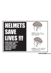
the road to fun
HELMETS
SAVE
LIVES!
CORRECT FITTING
MAKE SURE YOUR HELMET
COVERS YOUR FOREHEAD.
ALWAYS WEAR A PROPERLY FITTED
HELMET WHEN YOU RIDE YOUR BICYCLE.
DO NOT RIDE AT NIGHT. AVOID RIDING
IN WET CONDITIONS.
INCORRECT FITTING
FOREHEAD IS EXPOSED AND
VULNERABLE TO SERIOUS INJURY.
i
PLEASE RETAIN YOUR SALES RECEIPT AS PROOF
OF PURCHASE. FILL OUT THE INFORMATION BELOW
AND KEEP THIS MANUAL IN A SAFE PLACE.
BRAND/DESCRIPTION:
MODEL #:
PRODUCTION DATE:
SERIAL #:
DATE OF PURCHASE:
STORE/PLACE OF PURCHASE:
ii
ABOUT THIS MANUAL
This manual was written to help you get the most performance, comfort, enjoyment and safety when riding your new
bicycle. It is important for you to understand your new bike. By reading this manual before you go out on your first ride,
you’ll know how to get the most from your new bicycle. It is also important that your first ride on your new bicycle is
taken in a controlled environment, away from cars, obstacles, and other cyclists.
GENERAL WARNING
Bicycle riding can be a hazardous activity even under the best of circumstances. Proper maintenance of your bicycle
is your responsibility as it helps reduce the risk of injury. This manual contains many “WARNINGS” and “CAUTIONS”
concerning the consequences of failure to maintain or inspect your bicycle. Many of the warnings and cautions say,
“you may lose control and fall.” Because any fall can result in serious injury or even death, we do not repeat the warning
of possible injury or death whenever the risk of falling is mentioned.
Dynacraft does not encourage stunting, trick riding, ramp riding, jumping, aggressive riding, riding on severe terrain,
riding in severe climates, riding with heavy loads, riding double, commercial activities; such use is inherently dangerous,
can cause serious injury to the rider, and if done it is with the rider’s express and implied assumption of the risk of such
use and Dynacraft shall not have any responsibility for any breakdown of the bicycle, its components or rider injuries
that occur during such use.
iii
A SPECIAL NOTE FOR PARENTS
It is a tragic fact that most bicycle accidents involve children. As a parent or guardian, you bear the responsibility for the
activities and safety of your minor child. Among these responsibilities are to make sure that the bicycle which your child
is riding is properly fitted to the child: that it is in good repair and safe operating condition; that the play of young children is supervised by an adult; that you and your child have learned, understand and obey not only the applicable local
motor vehicle, bicycle and traffic laws, but also the common sense rules of safe and responsible bicycling. As a parent,
you should read this manual before letting your child ride the bicycle. Please make sure that your child always wears an
approved bicycle helmet when riding.
NOTE: The illustrations in this manual are used simply to provide examples; the components of your
bicycle might differ. In addition, some of the parts shown might be optional and not part of the
bicycle’s standard equipment.
iv
The following manual is only a guide to assist you and is not a complete or comprehensive manual of all aspects of
maintaining and repairing your bicycle. The bicycle you have purchased is a complex object. We recommend that you
consult a bicycle specialist if you have doubts or concerns as to your experience or ability to properly assemble, repair,
or maintain your bicycle. You will save time and the convenience of having to go back to the store if you choose to write
or call us concerning missing parts, service questions, operating advice, and/or assembly questions.
DYNACRAFT CUSTOMER SERVICE
1.800.551.0032
7AM to 4PM PACIFIC TIME
Model Number &
Production Date
Dynacraft BSC, Inc.
89 South Kelly Road,
American Canyon, CA 94503
www.dynacraftbikes.com
Serial Number
v
DIRECTORY
INDEX
vii
TOOLS
1
2-5
PARTS LIST/IDENTIFICATION
BEFORE YOU RIDE
6-25
ASSEMBLY
26-64
HOW THINGS WORK
65-75
SERVICING
76-78
DETAILED MAINTENANCE
TROUBLE SHOOTING
108-110
REGISTRATION CARD AND WARRANTY
111-116
WARNING/IMPORTANT
Take notice of this symbol throughout this manual
and pay particular attention to the instructions
blocked off and preceded by this symbol.
vi | DIRECTORY
79-107
DYNACRAFT BSC, INC.
89 South Kelly Road, American Canyon, CA
94503 Customer Service 1.800.551.0032
www.dynacraftbikes.com
1 Below the Bar Shifters
BICYCLE CARE
Basic Maintenance
2 Storage
3 Security
4 ASSEMBLY
5
DERAILLEUR GEARED
BIKES
6 Handlebars
6 Forks
7
8 Seat and Seat Post
10 Max./Min. Insertion Mark
14 Pedals and Crank Set
14 BRAKES
14 Cantilever with Link Wire
15 V-Style
Check your Brakes
16 Disk Brakes
16 DERAILLEUR
16 Rear Derailleur
16 Front Derailleur
17 Dual Suspension
17 Rear Pivots
17 Accessories
17 Reflectors
17 Front Fender Assembly
18 Basket Assembly
18 Rear Rack Assembly
Final Check
SINGLE SPEED & BMX
21 Frontwheel
21 Handlebars
22 Seat
23 Pedals and Crank Set
23 Hand Brake
Side Pull Brake
Cantilever
24 U-Brake
25 Check your Brakes
25 Training Wheels
Rotors
Final Check
26 HOW THINGS WORK
27 Removing Bolt on Wheels
30 Seatpost Quick Release
31 Brakes
32 Shifting
34 Tires and Tubes
Bicycle Suspension
35 SERVICING
37 Schedule 1 - Lubrication
40 Schedule 2 - Service
41 Checklist
DETAILED
42 MAINTENANCE
43 Wheel Inspection
44 Tire Inspection
45 Tire Pressures
46 Hub Bearing Adjustment
46 Flat Tire Repair
47 Handlebar Stem
49 Handlebars
50 Grip Shift Installation
51 Cables and Cable
Housing
52
52 HEADSET
53 Inspection
54 Adjustment
55
56
56
57
59
60
60
60
64
66
67
68
69
73
75
76
78
79
80
80
81
81
83
84
85
86
87
87
SADDLE & SEAT POST
Inspection
88
Lubrication
88
Saddle Adjustment
89
Adjustment Sidepull
91
Calipers
Adjustment Cantilever
Calipers
92
DRIVETRAIN
Pedals
94
94
-Inspection
-Lubrication and
Adjustment
95
-Attachment
95
Crankset
96
-Adjustment
98
Binder Crank
Replacement/Removal 100
-Chain
101
-Inspection
101
-Lubrication
101
-Adjustment and
Replacement
101
-Freewheel/Inspection
102
-Lubrication
103
-Coaster Hub
103
DERAILLEUR SYSTEMS
Inspection
104
Adjustment (front)
105
Lubrication
106
Adjustment (rear)
106
Reflectors
107
TROUBLESHOOTING 108
REGISTRATION CARD
& WARRANTY
111
INDEX
TOOLS
PARTS LIST/
IDENTIFICATION
Mountain Bicycles
Dual Suspension Bicycles
BMX Bicycles
Road Bicycles
BEFORE YOU RIDE
Standover Height
Frame Weight Limit
Correct Frame Size
Rules of the Road
Off Road/Rider Safety
Riding Position
Saddle Height
Reach
Handlebar Height
SAFETY CHECKLIST
Brakes
Wheels & Tires
Steering
Cranks & Pedals
Chain
Bearings
Derailleurs
Frame & Fork
Accessories
Helmets
Reflectors
GEARS - HOW TO
OPERATE
Derailleur Gears
Operating Principles
Hand Grip Shifters
Thumb Shifters
INDEX
| vii
TOOLS
TOOLS REQUIRED
1. Allen key wrenches: 4 mm, 5 mm, 6 mm, 8 mm
2. Adjustable wrench
3. Tire lever
4. Standard Phillips head screwdriver
5. Open end or pedal wrench 15 mm
6. Standard slip joint pliers
7. Tire pump
8. Standard flat head screwdriver
1
2
3
4
5
6
7
8
1
2
3
4
5
5
6
TRAVEL TOOLS
1. Spare Tube
2. Patch Kit
3. Pump
4. Tire Levers
5. Multi-tool
6. Change (phone call)
1|
TOOLS
Mountain bicycles are designed to give maximum comfort over a wide variety of road surfaces. The wider
handlebars and convenient shift lever position make them very easy to control. Wider rims and tires give them
a softer ride with more traction on rough surfaces. The frame and fork on mountain bicycles are much sturdier
than those on racing style bicycles.
Shift Lever
Brake Lever
Handlebar
Handlebar Stem
Seat
Seatpost
Rear Reflector
Front Reflector
Head Set
Head Tube
Top Tube
Brake Control Cable
Gear Control Cable
Quick Release
Front Reflector
Gear Control Cable
Down Tube
Seat Tube
Rear Brake
Front Derailleur
Seat Stay
Bottom Bracket
Axle
Freewheel
Wheel Reflector
Front Brake
Front Fork
Wheel Reflector
Front Hub
Spokes
PARTS LIST / IDENTIFICATION
MOUNTAIN BICYCLES
Chain Wheel
Rear Derailleur
Crank Arm
Pedal
Chain Guard
Tire
Rim
Chain Stay
Chain
Retaining Washer
Tire Valve
PARTS LIST / IDENTIFICATION
|2
PARTS LIST / IDENTIFICATION
DUAL SUSPENSION MOUNTAIN BICYCLES
Dual Suspension Mountain bicycles are designed to give maximum comfort over a wide variety of road surfaces.
Shift Lever
Brake Lever
Handlebar Stem
Head Set
Seat
Head Tube
Quick Release
Top Tube
Rear Reflector
Seatpost
Down Tube
Handlebar
Front Reflector
Gear Control Cable
Brake Control Cable
Pivot (behind chain wheel)
Rear Brake
Seat Stay
Freewheel
Front Derailleur
Wheel Reflector
Bottom Bracket
Axle
Chain Wheel
Front Brake
Front Fork
Wheel Reflector
Front Hub
Spokes
Crank Arm
Pedal
Chain Guard
Tire
Rim
Chain Stay
Chain
Rear Derailleur
3|
PARTS LIST / IDENTIFICATION
Retaining Washer
Tire Valve
BMX bicycles are a popular general purpose type most suited for young riders. They are valued because of their
sturdy and simple construction, and low maintenance.
Handlebar Grip
Brake Lever
Handlebar Stem
Handlebar
Head Set
Seat
Quick Release
Rear Reflector
Seatpost
Seat Stay
Wheel Reflector
Front Reflector
Brake Control Cable
Head Tube
Top Tube
Front Brake
Front Fork
Brake Pad
Wheel Reflector
Spokes
Front Hub
PARTS LIST / IDENTIFICATION
BMX BICYCLES
Down Tube
Seat Tube
Chain
Pedal
Rear Sprocket
Training Wheels
Crank Arm
Chain Wheel
(16” and smaller)
Chain Guard
Rim
Tire
Retaining Washer
Tire Valve
PARTS LIST / IDENTIFICATION
|4
PARTS LIST / IDENTIFICATION
ROAD BICYCLES
Road bicycles are designed for fast travel, hard training and competition on paved surfaces exclusively. It is the
lightest, most aerodynamic and “fastest” type of bicycle.
Shift Lever
Handlebar
Seat
Seatpost
Rear Reflector
Quick Release
Rear Brake
Seat Stay
Wheel Reflector
Freewheel
Handlebar Stem
Head Set
Head Tube
Front Reflector
Top Tube
Brake Lever
Seat Tube
Brake Control Cable
Front Brake
Front Fork
Wheel Reflector
Down Tube
Gear Control Cable
Front Derailleur
Chain Wheel
Front Hub
Spokes
Crank Arm
Pedal
Chain Guard
Bottom
Bracket Axle
Chain Stay
Chain
Gear Control Cable
Rear Derailleur
5|
PARTS LIST / IDENTIFICATION
Rim
Tire
Tire Valve
FRAME WEIGHT LIMIT
1. Diamond Frame Bicycles
Standover height is the basic element of bike fit (see
figure). It is the distance from the ground to the top
tube of the bicycle’s frame at that point where the top
of the inseam of your pants is when straddling the
bike. To check for correct standover height, straddle
the bike while wearing the kind of shoes in which you’ll
be riding, and bounce vigorously on your heels. If the
inseam touches the frame, the bike is too big for you.
Don’t even ride the bike around the block. A bike which
you ride only on paved surfaces and never take off-road
should give you a minimum standover height clearance
of one inch (2.6 cm). A bike that you’ll ride on unpaved
surfaces should give you a minimum of three inches (7.5
cm) of standover height clearance.
2. Step-Through Frame Bicycles
Standover height does not apply to bicycles with
step-through frames. Instead, the limiting dimension is
determined by comparing a diamond frame bike that
properly fits and then selecting the step-through bike of
the same size.
There is no American standard for testing the
structural weight limits of bicycle frames and for
each bike type our limits were determined through
lab testing using international standards that seemed
reasonable. Not all models were tested. Limits are
based on the test results for exemplars of a 20 inch
free style bicycle, a 26 inch diamond frame bicycle
and a 26 inch dual suspension frame bicycle.
WARNING
If your bicycle does not
fit properly, you may lose
control and fall. If your
new bike doesn’t fit, ask
your dealer to exchange
it before you ride.
Structural Weight Limit: The maximum
weight (rider and cargo) a bike frame can
physically support.
BEFORE YOU RIDE
STANDOVER HEIGHT
Rider Weight: The weight of the rider in riding
gear (e.g., jacket, helmet cam, hydration pack,
helmet, etc.).
CARGO WEIGHT: The weight of any
additional accessories (e.g., panniers, rear
racks, saddle bags, handlebar bags, baskets,
etc.) not accounted for in Rider Weight.
WEIGHT LIMIT: The maximum structural
weight recommendations for our bicycles that
are 20 inches or larger are:
· Free Style 20 inch bicycles: 176 lbs. (80 kg.).
· Diamond frame adult
bicycles up to 26 inches:
275 lbs. (125 kg.).
· Dual suspension frame adult
bicycles up to 26 inches:
275 lbs. (125 kg.).
BEFORE YOU RIDE
|6
BEFORE YOU RIDE
CORRECT FRAME SIZE
When selecting a new bicycle, the correct choice of frame size is a very important safety consideration.
CAUTION
For safe and comfortable riding there should
be a clearance of no less than 1 inch between
the inseam area of the intended rider and the
top tube of the bicycle frame, while the rider
straddles the bicycle with both feet flat on the
ground.
WARNING
If the bicycle is too large the rider cannot reach
the pedals easily, or the ground when stopping
which may result in loss of control and/or injury.
SAFE SIZING FOR JUVENILE AND SIDEWALK BICYCLES
It is assumed that the bicycle you have bought is sized correctly for the user. Some parents make the mistake
of buying a bicycle too large for the intended rider, planning on the child “growing into” it. There should be a
minimum of 1 inch clearance above the highest point of the top tube when the child is straddling the bicycle
with both feet on the ground (see drawing below).
7|
BEFORE YOU RIDE
NOTE: Like any sport, bicycling involves risk of injury and damage. By choosing to ride a bicycle, you
assume the responsibility for that risk; not the people who sold you the bike; nor the people who made it;
nor the people who distribute it; nor the people who manage or maintain the roads and trails you ride on.
YOU. So you need to know - and to practice - the rules of safe and responsible riding.
1. IN THE INTEREST OF SAFER CYCLING,
MAKE SURE YOU READ AND UNDERSTAND
YOUR OWNER’S MANUAL. NOTE AND
PERFORM PRE RIDE SAFETY CHECKS.
2. NOTICE: Some state and local laws may require
that your bicycle be equipped with a warning device
such as a horn or bell and a light if the bicycle is to be
ridden after dark.
3. ALWAYS WEAR SHOES when riding a bicycle and
AVOID LOOSE FITTING CLOTHES.
4. CHECK YOUR BRAKES FREQUENTLY. THE
ABILITY TO STOP YOUR BICYCLE IS CRITICAL.
Roads are slippery when wet so avoid sharp turns and
allow more distance stopping. Caliper brakes may
become less efficient when wet. Leaves, loose gravel,
and other debris can also effect stopping.
5. ALWAYS RIDE IN THE SAME DIRECTION AS
TRAFFIC. Never ride against traffic.
LEFT
6. STOP AND LOOK BEFORE YOU LEAVE AN ALLEY,
DRIVEWAY, OR PARKING LOT. Stop, look to the left,
to the right, and to the left again for traffic. Ride only
when it is clear.
7. KEEP TO THE RIGHT. Follow the traffic flow in a
straight line and stay close to the curb. Watch for cars
moving in and out of traffic.
BEFORE YOU RIDE
RULES OF THE ROAD AND SAFETY TIPS
8. OBEY ALL TRAFFIC LAWS REGULATIONS. Most
traffic regulations apply to bike riders as well as
automobile operators.
9. ALWAYS RIDE ALONE. NEVER CARRY OTHER
RIDERS. This is dangerous and makes the bike harder
to control. The bicycles distributed by Dynacraft BSC,
Inc. are intended for one rider only.
10. ALWAYS BE ALERT. Be ALERT - pedestrians have
the right of way. Be ALERT - when riding near parked
cars - ride far enough away from the cars so that you
won’t get hit if someone opens the car door.
STOP
RIGHT
BEFORE YOU RIDE
|8
BEFORE YOU RIDE
RULES OF THE ROAD AND SAFETY TIPS (continued)
11. USE CAUTION AT ALL INTERSECTIONS AND
STOP SIGNS. STOP AND LOOK BOTH WAYS
BEFORE PROCEEDING.
12. USE HAND SIGNALS. Communicate by using
hand signals to tell other drivers what you are going to
do. Signal 100 feet before turning unless your hand is
needed to control the bike (see page 8 for hand signal
instructions).
13. HAVE PROPER LIGHTS AND REFLECTORS. IF
YOU RIDE AT NIGHT, be sure to have a strong headlight, a tail light, and a full set of reflectors. CHECK
THAT REFLECTORS ARE CLEAN, STRAIGHT, UNBROKEN,
AND SECURELY MOUNTED.
14. NEVER CARRY PACKAGES OR OBJECTS
WHICH OBSTRUCT VISION.
9|
THE BICYCLE ONLY, not the bicycle and the rider.
17. AVOID THE FOLLOWING HAZARDS: Drain grates,
potholes, soft road edges, gravel, sand, wet leaves,
and/or any obstruction in the road. Failure to do so
could cause wheel(s) to buckle and result in personal
injury to the rider.
18. WET WEATHER RIDING - Riding your bicycle in
wet conditions is not recommended. In wet conditions
traction and braking power is reduced. Riding in such
conditions could result in personal injury.
19. PROPER HELMET USE. A helmet that meets
the CPSC (Consumer Product Safety Commission)
standard should always be worn when riding a bicycle.
The helmet should fit properly and worn on the crown
of the head, not tipped back.
15. NEVER HITCH RIDES, never hold onto a moving
vehicle while riding.
20. USE BIKE LANES when available. Also note that in
certain states, cars may use bike lanes when turning.
16. THE KICKSTAND IS DESIGNED TO SUPPORT
21. Respect “Bicycles Are Prohibited” signs.
BEFORE YOU RIDE
We recommend that children not ride on rough terrain unless they are accompanied by an adult. Off road riding
on approved trails with appropriate protective equipment can be done with mountain bikes and BMX bikes if
you have the skill and experience necessary to maintain control. Whether you call it Aggro, Hucking, Freeride,
North Shore, Downhill, Jumping, Stunt Riding, Racing or something else: it is NOT off road riding, it is NOT
recommended and if you engage in this sort of extreme, aggressive riding you will get hurt, and you voluntarily
assume a greatly increased risk of injury or death. Dynacraft bicycles are not designed for these types of
extreme riding.
WARNING
Although many catalogs, advertisements and articles about bicycling
depict riders engaged in extreme riding, this activity is extremely
dangerous, increases your risk of injury or death, and increases the
severity of any injury. Remember that the action depicted is being
performed by professionals with many years of training and
experience. Even with state-of-the-art protective safety gear, you
could be seriously injured or killed when jumping, stunt riding,
riding downhill at speed or in competition.
WARNING
Bicycles and bicycle parts have
limitations with regard to strength
and integrity, and this type of
riding can exceed those limitations.
BEFORE YOU RIDE
OFF ROAD SAFETY
The variable conditions and hazards of off-road riding require close attention and specific skills. Start slowly on
easier terrain and build up your skills. If your bike has suspension, the increased speed you may develop also
increases your risk of losing control and falling. Get to know how to handle your bike safely before trying increased speed or more difficult terrain.
1. Wear safety gear appropriate to the kind of riding you plan to do.
2. Don’t Ride alone in remote areas. Even when riding with others, make sure that someone knows where
you’re going and when you expect to be back.
3. Always take along some kind of identification, so that people know who you are in case of an accident;
and take along some cash for food, a cool drink or an emergency phone call.
BEFORE YOU RIDE
| 10
BEFORE YOU RIDE
(continued)
4. Yield right of way to pedestrians and animals. Ride in a way that does not frighten or endanger them, and
give them enough room so that their unexpected moves don’t endanger you.
5. Be prepared. If something goes wrong while riding off-road, help may not be close.
6. Do NOT attempt to jump, do stunt riding or race with your bike.
OFF ROAD RESPECT
Obey the local laws regulating where and how you can ride off-road, and respect private property. You may be
sharing the trail with others — hikers, equestrians, other cyclists. Respect their rights. Stay on the designated
trail. Don’t contribute to erosion by riding in mud or with unnecessary sliding. Don’t disturb the ecosystem by
cutting your own trail or shortcut through vegetation or streams. It is your responsibility to minimize your impact
on the environment. Leave things as you found them; and always take out everything you brought in.
WET WEATHER RIDING
Under wet conditions, the stopping power of your brakes (as well as the brakes of other vehicles sharing the
road) is dramatically reduced and your tires don’t grip nearly as well. This makes it harder to control speed and
easier to lose control. Dynacraft does not recommend that you ride under these conditions.
WARNING
Wet weather impairs traction, braking and visibility, both for
the bicyclist and for other vehicles sharing the road. The risk
of an accident is dramatically increased in wet conditions.
11 |
BEFORE YOU RIDE
Riding a bicycle at night is much more dangerous than riding during the day. A bicyclist is very difficult for
motorists and pedestrians to see. Therefore, children should never ride at dawn, at dusk or at night. Adults who
choose to accept the greatly increased risk of riding at dawn, at dusk or at night need to take extra care both
riding and choosing specialized equipment which helps reduce that risk. Consult your dealer about night riding
safety equipment.
WARNING
Reflectors are not a substitute for required lights.
Riding at dawn, at dusk, at night or at other times of
poor visibility without an adequate bicycle lighting
system and without reflectors is dangerous and
may result in serious injury or death.
WARNING
Do not remove the front or rear reflectors or
reflector brackets from your bicycle. They are an
integral part of the bicycle’s safety system. Removing the reflectors reduces your visibility to
others using the roadway. Being struck by other
vehicles may result in serious injury or death.
BEFORE YOU RIDE
NIGHT RIDING
PEDALING TECHNIQUE
• Position the ball of your foot on the corner of the pedal.
• When pedaling, ensure your knees are parallel to the bike frame.
• To absorb shock, keep your elbows slightly bent.
• Learn to operate the gears properly (refer to pages 21-23).
HILL TECHNIQUE
• Gear down before a climb and continue gearing down as required to maintain pedaling speed.
• If you reach the lowest gear and are struggling, stand up on your pedals. You will then obtain
more power from each pedal revolution.
• On the descent, use the high gears to avoid rapid pedaling.
• Do not exceed a comfortable speed, maintain control and take additional care.
BEFORE YOU RIDE
| 12
BEFORE YOU RIDE
CORNERING TECHNIQUE
Brake slightly before cornering and prepare to lean your body into the corner. Maintain the inside pedal at the
12 o’clock position and slightly point the inside knee in the direction you are turning. Keep the other leg straight,
don’t pedal through fast or tight corners.
RULES FOR CHILDREN
To avoid an accident, teach children good riding skills with an emphasis on safety from an early age.
1. Always wear a properly fitted helmet.
2. Do not play in driveways or the road.
3. Do not ride on busy streets.
4. Do not ride at night.
5. Obey all traffic laws, especially stop signs
and red lights.
6. Be aware of other road vehicles behind and nearby.
7. Before entering a street: Stop, look left, right, and
left again for traffic.
8. If riding downhill, be extra careful. Slow down using
the brakes and maintain control of steering.
9. Never take your hands off the handlebars, or your
feet off the pedals when riding downhill.
CAUTION
The Consumer Product Safety Commission
advises that the riding of small wheel diameter
bicycles at excessive speeds can lead to
instability and is not recommended.
Children should be made aware of all possible riding hazards and
correct riding behavior before they take to the streets.
DO NOT LEAVE IT UP TO TRIAL AND ERROR.
13 |
BEFORE YOU RIDE
Saddle Height
In order to obtain the most comfortable riding position and offer
the best possible pedaling efficiency, the seat height should be
set correctly in relation to the rider’s leg length. The correct saddle
height should not allow leg strain from over-extension, and the
hips should not rock from side to side when pedaling. While sitting
on the bicycle with one pedal at it’s lowest point, place the ball of
your foot on that pedal. The correct saddle height will allow the
knees to be slightly bent in this position. If the rider then places the
heel of that foot on the pedal, the leg should be almost straight.
BEFORE YOU RIDE
RIDING POSITION
Reach
To obtain maximum comfort, the rider should not overextend his
or her reach when riding. To adjust the distance, the position of
the seat can be altered in relation to the seat pillar.
CAUTION
Under no circumstances should the seatpost project from the
frame beyond its “Minimum Insertion” or “Maximum Extension”
mark. If your seatpost projects from the frame beyond these
markings, the seatpost or frame may break, which could cause
you to lose control and fall. After any saddle adjustment, be sure
to tighten the saddle adjusting mechanism properly before
riding. A loose saddle clamp or seatpost binder can cause
damage to the bicycle or can cause you to loose control and fall.
Periodically check to make sure that the saddle adjusting
mechanism is properly tightened.
BEFORE YOU RIDE
| 14
BEFORE YOU RIDE
HANDLEBAR HEIGHT
Maximum comfort is usually obtained when the handlebar
height is equal to the height of the seat. You may wish to try
different heights to find the most comfortable position.
WARNING
Over tightening the stem bolt or headset assembly
may cause damage to the bicycle and/or injury to
the rider.
WARNING
The stem’s “Minimum Insertion” mark must not be
visible above the top of the headset. If the stem is
extended beyond this mark, the stem may break or
damage the fork’s steerer tube, which could cause
you to lose control and fall.
15 |
BEFORE YOU RIDE
CAUTION
Failure to properly tighten the stem wedge bolt,
the handlebar binder bolt, or the bar end extension clamping bolts may compromise steering
action, which could cause you to lose control
and fall. Place the front wheel of the bicycle
between your legs and attempt to twist the
handlebar/stem assembly. If you can twist the
stem in relation to the front wheel, turn the bar
end extensions in relation to the handlebar, you
must tighten the appropriate bolts accordingly.
Before every ride, it is important to carry out the following safety checks: (For information and instructions on
performing specific equipment checks, locate the relevant section in the manual using the index on page vii).
1. Brakes
• Ensure front and rear brakes work properly.
• Ensure brake shoe pads are not over worn and are correctly positioned in relation to the rims.
• Ensure brake control cables are lubricated, correctly adjusted, and display no obvious wear.
• Ensure brake control levers are lubricated and tightly secured to the handlebar.
2. Steering
• Ensure handlebar and stem are correctly adjusted and tightened, and allow proper steering.
• Ensure that the handlebars are set correctly in relation to the forks and the direction of travel.
• Check that the head set locking mechanism is properly adjusted and tightened.
• If the bicycle is fitted with handlebar end extensions, ensure they are properly positioned
and tightened.
BEFORE YOU RIDE
SAFETY CHECKLIST
3. Cranks and Pedals
• Ensure pedals are securely tightened to the cranks.
• Ensure cranks are securely tightened to the axle and are not bent.
4. Wheels and Tires
• Ensure tires are inflated to within the maximum recommended limit as displayed on the
tire sidewall.
• Ensure tires have tread and have no bulges or excessive wear.
• Ensure rims run true and have no obvious wobbles or kinks.
• Ensure all wheel spokes are tight and not broken.
• Check that axle nuts are tight.
BEFORE YOU RIDE
| 16
BEFORE YOU RIDE
5. Chain
• Ensure chain is oiled, clean and runs smoothly.
• Extra care is required in wet or dusty conditions.
• On bicycles equipped with coaster brakes, check for proper chain tension.
6. Derailleurs
• Check that front and rear mechanisms are adjusted and function properly.
• Ensure control levers are securely attached.
• Ensure derailleurs, shift levers and control cables are properly lubricated.
7. Bearings
• Ensure all bearings are lubricated, run freely and display no excess movement, grinding
or rattling.
• Check headset, wheel bearings, pedal bearings and bottom bracket bearings.
8. Frame and Fork
• Check that the frame and fork are not bent or broken.
• If either are bent or broken, they should be replaced.
9. Accessories
• Ensure that all reflectors are properly fitted and not obscured.
• Ensure all other fittings on the bike are properly and securely fastened, and functioning.
• Ensure the rider is wearing a helmet.
17 |
BEFORE YOU RIDE
BEFORE YOU RIDE
HELMETS
Local laws of most places require a helmet, and common sense
requires them in other places where it is not the law. It is strongly
advised that a properly fitting, CSPC approved, bicycle safety
helmet be worn at all times when riding your bicycle. In addition, if
you are carrying a passenger in a child safety seat, they must also
be wearing a properly fitted helmet.
The correct helmet should:
• be comfortable
• be lightweight
• have good ventilation
• fit correctly
WARNING
Always wear a properly fitted helmet when riding a bicycle. Falling off your bicycle without a helmet can cause
serious injury or death. Many states require specific safety devices. It is your responsibility to familiarize yourself
with the laws of the state where you ride and comply with all applicable laws, including properly equipping yourself and your bike as the law requires. Reflectors are important safety devices which are designed as an integral
part of your bicycle. Federal regulations require most types of bicycles to be equipped with front, rear, wheel,
and pedal reflectors. These reflectors are designed to pick up and reflect street lights and car lights in a way
that helps you to be seen and recognized as a moving bicyclist. Check reflectors and their mounting brackets
regularly to make sure they are clean, straight, unbroken, and securely mounted. Replace damaged reflectors
and straighten or tighten any that are bent or loose.
REFLECTORS
Your bicycle is supplied with one front (white), one rear (red), two wheel (white), and two pedal (orange) reflectors. These are an important safety and legal requirement, and should remain securely fitted and in good, clean
conditions at all times. Periodically, inspect all reflectors, brackets, and mounting hardware for signs of wear or
damage. Replace immediately if damage is found. Some bicycles will require you to install your reflectors onto
your bicycle.
BEFORE YOU RIDE
| 18
BEFORE YOU RIDE
Please refer to the following section for instructions on all types of
bicycle reflectors.
NOTE: CPSC Regulations do not require reflectors on 10”, 12” and 16”
Sidewalk Bicycles - We recommend, however, that you attach reflectors for the protection of the rider. These types of bicycles should be
operated during daylight hours only, on a smooth, paved surface such
as a sidewalk, under the direct supervision of an adult. These bicycles
should never be ridden in the street, on an incline, or on rough terrain.
Under no circumstances should these types of bicycles be operated at
speeds that would make it difficult to control, nor should it be raced or
used for stunting, jumping, motocross, or off-road use or other activities not normally associated with a Sidewalk Bicycle.
FRONT MOUNT REFLECTOR BRACKET ASSEMBLY
Slide reflector over bracket as shown in diagram and ensure that the tab
clicks into the top hole of the bracket. Insert one washer onto the hex bolt
and insert hex bolt through the reflector bracket and then through the fork.
Next, insert a second washer onto the bolt and thread a hex nut onto the
bolt behind the fork. Tighten bolts until snug, making sure the reflector is in
an upright position.
WHEEL REFLECTORS
The wheel reflectors should come already attached to the spokes of both
the front and rear wheels. To attach reflector to the wheel, fit the groove in
the reflector to a spoke that matches the groove. The reflector should be
mounted across from the valve stem and as close to the rim as possible.
The reflector should fit firmly between a single spoke on one side and two
spokes on the other. Use the supplied clip (with two locking prongs), fit
the clip over the spoke and into the hole and press until the locking prongs
“click” into place. Be sure to fit reflectors to both wheels.
19 |
BEFORE YOU RIDE
Slide reflector over bracket (shown on page 19) and ensure that the tab clicks into the top hole of the bracket.
Next, remove the clamp screw and open the clamping reflector bracket. Place clamping reflector bracket
around the handlebar or seatpost. If the clamp is too loose, insert the shim inside of the clamp. Tighten the
clamp screw to hold reflector assembly in place. Finally, adjust the reflector such that it is upright and facing
away from the bike.
SEATPOST MOUNT REFLECTOR BRACKET ASSEMBLY
Slide reflector over bracket as shown in diagram below and ensure that the tab clicks into the top hole of the
bracket. Insert one washer onto the hex bolt and insert hex bolt through the reflector bracket and around the
seatpost. Tighten bolts until snug, making sure the reflector is in an upright position. See diagram below.
BEFORE YOU RIDE
SEAT AND HANDLEBAR MOUNTING REFLECTORS
PEDAL REFLECTORS
Pedal reflectors are required by federal law. Maintain them and replace any that are missing.
BEFORE YOU RIDE
| 20
BEFORE YOU RIDE
GEARS - HOW TO OPERATE
Derailleur Gears
Most multi-speed bicycles today are equipped with what
are known as derailleur gears. They operate using a system
of levers and mechanisms to move the drive chain between
different sized driving gears or cogs. The purpose of gears
is to let you maintain a constant, steady pedaling pace
under varying conditions. This means your riding will be
less tiring without unnecessary straining up hills or fast
pedaling down hill. Bicycles come with a variety of gear
configurations from 5 to 27 speeds. A 5-6 speed bicycle
will have a single front chain-wheel, a rear derailleur, and
5 or 6 cogs on the rear hub. Bicycles with more gears will
also have a front derailleur, a front chainwheel with 2-3
cogs, and up to 7 cogs on the rear hub.
Operating Principles
No matter how many gears, the operating principles are
the same. The front derailleur is operated by the left shift
lever and the rear derailleur by the right. To operate, you
must be pedaling forward. You can not shift derailleur
gears when you are stopped or when pedaling backwards.
Before shifting, ease up on your pedaling pressure. For
a smooth gear change when approaching a hill, shift to a
lower gear BEFORE your pedaling speed slow down too
much. When coming to a stop, shift to a lower gear first so
it will be easier when you start riding again. If, after
selecting a new gear position, you hear a slight rubbing
noise from the front or rear gears, gently adjust the
appropriate shifter using the barrel adjusters until the noise
goes away. For optimal performance and extended chain
life, it is recommended that you avoid using the extreme
combinations of gear positions (diagram page 22) for
extended periods.
21 |
BEFORE YOU RIDE
DRIVE TRAIN
Front Derailleur
Derailleur
Control Cable
Freewheel Cogs
Pedal
Guide Pulley
Rear Derailleur
CAUTION
Front Chainwheels
Crank Arm
Children under age 9 should only ride single
speed bicycles as they do not have capability
to use shifters.
BEFORE YOU RIDE
High
Middle
Low
For optimal performance,
NOT RECOMMENDED
High
Low
For optimal performance,
NOT RECOMMENDED
Recommended Chainwheel/Rear Sprocket Gear Combinations
Front Low Gear
Rear Low Gear
Front High Gear
Rear High Gear
Hand Grip Shifters
Many bicycles are now being equipped with a shifting
mechanism that is built into the handlebar grips and does
not make use of separate levers. The shifting is built into
the inside part of the grip that allows the thumb and index
finger around. To select a lower gear, twist the grip towards you to engage a larger rear cog. You can shift one
gear at a time by moving the shifter one click, or through
multiple gears by continuing twisting. By twisting the left
shifter forward or away from you, a smaller chainwheel can
be selected. To select a higher gear, twist the right shifter
forward or away from you to engage a smaller rear cog.
To engage a larger front chainwheel, twist the left shifter
towards you.
NOTE: Some bicycles may be equipped with a rear derailleur
mechanism that works in reverse to the direction above.
BEFORE YOU RIDE
| 22
BEFORE YOU RIDE
Left hand lever
BEFORE YOU RIDE
Thumb Shifters (Top Mounted)
Many mountain style bicycles are equipped with shifters
mounted on the top of the handlebars and operated by
the thumbs. To select a lower, easier gear, shift to a bigger
rear cog and a small chainwheel. Pull the left shifter back
to operate the rear derailleur. To select a higher, harder
gear, shift to a smaller rear cog and a larger chainwheel.
Push the left shifter forward for the front, and pull the right
lever back for the rear.
Top Gear
(Harder)
Small rear sprocket
Large chainwheel
Left hand lever forward
Right hand lever back
Left hand lever
23 |
Right hand lever
Right hand lever
Bottom Gear
(Easier)
Large rear sprocket
Small chainwheel
Left hand lever back
Right hand lever forward
Below the Bar Shifters
Many mountain style bicycles now use a shift lever
arrangement mounted on the underside of the handlebars,
which use two levers operated by the thumb and index
finger. To select a lower gear, push the larger (lower) right
shifter with your thumb to engage a larger rear cog. One
firm push shifts the chain one cog, continuing to push will
move the chain over multiple cogs. Pulling the smaller
(upper) right lever with your index finger to engage a
smaller rear cog. Pushing the larger (lower) left lever with
your thumb will move the chain from a smaller to a
larger chainwheel.
Basic Maintenance
The following procedures will help you maintain your bicycle for years of enjoyable riding.
• Before you ride, check the alignment of the front wheel. If it is in alignment, you should see it if when lifting the
front of the bike and spinning the wheel, the gaps between the front brake pads are consistently the same. If
you do not see this, your wheels need truing.
CAUTION: Wheels must be true for rim brakes to work effectively. Wheel truing is a skill which requires
special tools and experience. Do not attempt to true a wheel unless you have the knowledge, experience and tools
needed to do the job correctly. See a qualified bike technician to properly true wheels.
BEFORE YOU RIDE
BICYCLE CARE
• For painted frames, dust the surface and remove any loose dirt with a dry cloth. To clean, wipe with a damp
cloth soaked in a mild detergent mixture. Dry with a cloth and polish with car or furniture wax. Use soap
and water to clean plastic parts and rubber tires. Chrome plated bikes should be wiped over with a rust
preventative fluid.
• Store your bicycle under shelter. Avoid leaving it in the rain or exposed to corrosive materials. Riding on the
beach or in coastal areas exposes your bicycle to salt which is very corrosive. Wash your bicycle frequently and
wipe or spray all unpainted parts with an anti-rust treatment. Make sure wheel rims are dry so braking
performance is not affected. After rain, dry your bicycle and apply anti-rust treatment.
• If the hub and bottom bracket bearings of your bicycle have been submerged in water, they should be taken
out and regreased. This will prevent accelerated bearing deterioration.
• If paint has become scratched or chipped to the metal, use touch up paint to prevent rust. Clear nail polish
can also be used as a preventative measure. Your local hobby shop will carry paints in small containers and a
variety of colors that you can use to touch up paint.
• Regularly clean and lubricate all moving parts, tighten components and make adjustments as required (refer to
pages 76-78 of this manual for further details).
The selected use of alloy component and surface treatments helps prevent rust and corrosion from affecting
some areas of your bicycle.
BEFORE YOU RIDE
| 24
BEFORE YOU RIDE
STORAGE
Keep your bicycle in a dry location away from the weather and the sun. Ultraviolet rays may cause paint to fade
or rubber and plastic parts to crack. Before storing your bicycle for a long period of time, clean and lubricate
all components and wax the frame. Deflate the tires to half pressure and hang the bicycle off the ground. Don’t
store near electric motors as ozone emissions may effect the rubber and paint. Don’t cover with plastic as
“sweating” will result which may cause rusting.
Please notice that your bicycle warranty does not cover paint damage, rust, corrosion, dry rot, or theft.
SECURITY
It is advisable that the following steps be taken to prepare
for and help prevent possible theft.
1. Maintain a record of the bicycle’s serial number,
generally located on the frame underneath the
bottom bracket.
2. Register the bicycle with the local police.
3. Invest in a high quality bicycle lock that will resist hack
saws and bolt cutters. Always lock your bicycle to an
immovable object if it is left unattended.
25 |
BEFORE YOU RIDE
Includes 20”, 24”, and 26” Wheel Mountain Bikes. Assembly is the same for men’s and women’s bikes.
FOREWORD: Assembling a bicycle is an important responsibility. Proper assembly not only gives the rider more
enjoyment of the bicycle, it also offers an important measure of safety.
Getting Started
Open the carton from the top and remove the bicycle. Remove the straps
and protective wrapping from the bicycle. Inspect the bicycle and all
accessories and parts for possible shortages. It is recommended that the
threads and all moving parts in the parts package be lubricated prior to
installation. Do not discard packing materials until assembly is complete
to ensure that no required parts are accidentally discarded. Assemble your
bicycle following the steps that pertain to your model.
NOTE: Your bicycle may be equipped with different style
components than the ones illustrated.
Front Wheel
1. Make sure the brakes are loose enough to allow the wheel to pass through
the brake pads easily.
Axle
Hub
Axle Nut
2. Place wheel into fork drop outs.
3. Install retaining washers with raised lip pointed towards the fork, and insert
into the small hole of the fork blade.
4. Install axle nut and securely tighten. Make sure the wheel is centered
between the fork blades.
5. Spin the wheel to make sure that it is centered and clears the brake shoes.
Retaining
Fork
Cone Nuts
Washer
Tighten the brakes if necessary.
Drop Out
6. If the wheel is out of alignment you will need to true the wheel; when spinning the wheel and notice the gaps between the brake pads are not consistently the same, the wheel needs truing. See a qualified bike technician to
true wheels.
WARNING
It is very important to check the front wheel connection to
the bicycle. Failure to properly tighten may cause the front
wheel to dislodge, resulting in a lose of control, injury or
even death.
ASSEMBLY
DERAILLEUR GEARED BICYCLES
CAUTION
Wheels must be true for rim brakes to work effectively.
Wheel truing is a skill which requires special tools and
experience. Do not attempt to true a wheel unless you
have the knowledge, experience and tools needed to do
the job correctly.
ASSEMBLY
| 26
ASSEMBLY
HANDLEBARS
Most of our bikes are equipped with a “quill” stem (figure X). To assemble the handlebars remove the
protective cap from the wedge end of the stem bolt and loosen the bolt using the 6 mm Allen key. Some
models may use a 13 mm hexagonal bolt instead of an Allen key bolt. Place the handlebar stem into the top
of the steer tube which is the top end of the fork that has been inserted into the head tube at the factory,
ensuring that all cables are free of tangles. Tighten the stem bolt observing the Minimum Insertion Mark
and checking that the forks and the handlebars are facing forward. After the stem bolt is tested tight (see
Important Note below), adjust handlebars to correct position. Loosen the 6 mm Handlebar Binder Bolt (See
Figure X) and rotate the handlebar forward so the brake levers are at a 45 degree angle below the handlebar.
Retighten the Binder Bolt to ensure the handlebar does not rotate in the stem. After the handlebar stem has
been fitted into the steer tube that is the top end of the fork and the two pieces made firm within the head
tube the action of a stem bolt upon the wedge nut binds with the inside of the steer tube to form a solid
steering column.
FIGURE X
Handlebar Binder Bolt
Stem Wedge Bolt
Top Nut
Wedge
WARNING
A loose stem bolt can cause a loss of steering control
and result in serious injury or death. The stem must be
tight enough for the wedge nut to bite into the inner
surface of the steer tube.
Minimum
Insertion Mark
Head Tube
Important Note: Test the security of the handlebar stem within the steer tube of the front fork by
clamping the front wheel between your knees and trying to move the handlebar and/or stem from side
to side. The handlebar should not move independent from the front wheel when applying pressure.
27 |
ASSEMBLY
ASSEMBLY
FIGURE Y
Stem Binder Bolt
Top Cap
Spacer
A
Handlebar
Handlebar Stem
Clamp Bolts
Steerer Clamp Bolts
A
Spacer
Compress
Upper Headset Cup
Upper Cone
Handlebar Stem Clamp
Bearing Retainer
Star Nut
(inside steerer tube)
Installed
by Factory
Headtube
Lower Headset Cap
Bearing Retainer
Headset Crown Race
Fork
You can adjust the handlebar height a bit by adjusting
stem height. A quill stem has an etched or stamped
mark on its shaft which designates the stem’s “Minimum
Insertion” or “Maximum Extension”. This mark must not
be visible above the headset. There are different styles
of handlebar clamps, but all attach to the bicycle with a
stem bolt and wedge nut.
WARNING
A quill stem’s Minimum Insertion Mark must not be
visible above the top of the headset. If the stem is
extended beyond the Minimum Insertion Mark the
stem may break or damage the fork’s steerer tube,
which could cause you to lose control and fall.
If your bike has a “threadless” stem (figure Y) the stem
has been installed in the factory and to change handlebar
height requires moving height adjustment spacers
from below the stem to above the stem, or vice versa.
Otherwise, you’ll have to get a stem of different length
or rise. Do not attempt to do this yourself, as it requires
special knowledge and your bicycle should be taken to a
professional bike shop for this adjustment.
ASSEMBLY
| 28
ASSEMBLY
ROTATION OF SHIFTERS, BRAKE
LEVERS AND BAR ENDS
FIGURE 1
Shifter binder bolt
(2.5 Allen key)
Tighten all bolts that clamp the shifter, brake
levers, and bar ends to the handlebar using a
5 mm Allen key or Phillips head screwdriver.
(figure 1) Handlebar with grip shifter.
(figure 2) Top mounted thumb shifter.
NOTE: When assembling the bicycle or
setting it up for a rider, the shifters, brake
levers and bar ends may need to be rotated
on the handlebars to a position that allows
safe and easy operation of the controls.
Bar end (5 mm Allen key)
Brake lever binder bolt
(5 mm Allen key)
FIGURE 2
Shift binder bolt
(Phillips head or
5 mm Allen key)
29 |
ASSEMBLY
WARNING
Failure to properly tighten clamping bolts may
cause sudden movement of the component
resulting in loss of steering control, and serious
injury or death.
There are two different types of forks that range in styles and
dimensions. One type is a rigid fork (figure 1) consisting of stationary
tubing with curved blades. The other type is a suspension fork
(figure 2) consisting of stanchion tubes riding on elastomers or
springs inside of a straight fork leg. This mechanism acts as a shock
absorber with a specified amount of travel that varies between
models. If service is needed on a suspension fork, consult a
professional bicycle repair technician.
FIGURE 1
Steering Tube
Brake Boss
Drop-out
ASSEMBLY
FORKS
Crown
CAUTION
Do not attempt to disassemble a suspension fork yourself.
Consult a professional bicycle repair technician.
Check the tightness of the headset and the fork. Rotate the fork
checking for smoothness. If it feels like the fork is binding, then an
adjustment will need to be made to the headset. Move the fork in a
push/pull manner checking for tightness. If any play is detected,
loosen the top nut (shown on page 87). Recheck the rotation and
tightness. If necessary, readjust until a smooth rotation is achieved
without backward or forward movement. If your bike is equipped
with a suspension fork, check that the fork compresses and
rebounds smoothly. To do this, place the fork dropouts against
the ground, push and release the handlebar. The fork will generally
compress 1 - 2 inches and rebound quickly. Most elastomer type
forks will gradually soften with use.
Fork Leg
FIGURE 2
Brake Bridge
Crown
Brake Boss
Drop-out
Steering Tube
Fork Leg
ASSEMBLY
| 30
ASSEMBLY
SEAT AND SEATPOST
Seat
Clamp
Seatpost
Quick
Release
Adjusting Nut
Attach the seat to the seatpost by loosening the nuts on the seat
clamp. Insert the tapered end of the seatpost into the seat clamp
until it is at the top of the clamp. Partially tighten the nuts on the
seat clamp turning each side evenly until the seat is snug, but
can still be turned. Insert the seat assembly into the frame of the
bicycle and adjust the seat to the proper height. The seatpost must
be inserted to at least the “Minimum Insertion” line marked on the
seatpost. If equipped with a quick release, tighten the adjusting nut
by hand and move the quick release lever to the closed position.
You should feel considerable resistance while moving the lever.
If not, reopen and retighten the lever, then move it to the closed
position so it is in line with the frame as pictured. Ensure the lip on
the binder clamp is fitted completely against the top of the seat
tube of the frame. With the seatpost inserted, tighten the binder
bolt securely. Position the top of the seat parallel with the ground.
Push the front of the seat up and down to firmly mesh the serrations
together. The serrations must mesh completely together to ensure
a stabilized riding position. Securely tighten the nut on the seat
clamp. If there is a nut on both sides of the clamp, tighten each one
by alternating from one to the other. Check for tightness by twisting
the seat from side to side, and from front to back. If the seat moves
at the seat clamp or quick release, reposition and retighten the
appropriate clamping mechanism.
NOTE: Comfort style bicycles may be equipped with a
suspension seatpost (see diagram - upper left).
31 |
ASSEMBLY
CORRECT MAXIMUM INSERTION
Do not insert below Maximum Insertion
Mark - insertion below Maximum Insertion
Mark will block rear reflector visibility.
Maximum Seatpost
Insertion Mark
Reflector
Bracket
Minimum
Insertion
Mark
Use reflector bracket Minimum Insertion
Mark to confirm rear reflector visibility
when adjusting seatpost or reflector
bracket.
INCORRECT MAXIMUM INSERTION
Reflector visibility is blocked
by rear fender when seatpost
is inserted incorrectly.
ASSEMBLY
SEATPOST MAXIMUM AND MINIMUM INSERTION MARK
Minimum Seatpost
Insertion Mark
Seatpost
This bike is equipped with a seatpost
which has Maximum and Minimum
Insertion Marks.
CORRECT MINIMUM INSERTION
INCORRECT MINIMUM INSERTION
WARNING
The seatpost must be inserted so that the
Minimum Insertion Mark cannot be seen.
The quick release mechanism must be
tightened securely to prevent a sudden
shift of the seat when riding. Failure to do
this may cause loss of bicycle control and
serious injury or death.
Always insert
seatpost past
Minimum
Insertion Mark.
Failure to insert
properly may result
in injury and
damage to bicycle.
ASSEMBLY
| 32
ASSEMBLY
Attach
Seat Here
NOTE: Comfort style bicycles may
be equipped with a suspension
seatpost (see diagram - left).
Boot
Minimum
Insertion Mark
Insert this
end into
frame
33 |
ASSEMBLY
Check for the right (R, red) sticker and left (L, green) sticker on each
pedal and crank arm. Match the appropriate pedal to each crank
(right to right and left to left) for assembly. Start each pedal spindle
by hand to avoid stripping the threads. Tighten with a 15 mm narrow open ended wrench so that the shoulder of the pedal spindle is
securely tightened against the crank arm. Note that the right hand
pedal attaches to the chainwheel side crank arm with a right-hand
(clockwise) thread. The left pedal attaches to the other crank arm
and has a left-hand (counter-clockwise) thread. It is very important
that you check the crank set for correct adjustment and tightness
before riding your bicycle.
ASSEMBLY
PEDALS AND CRANK SET
Dust Cap
New three piece cranks whether bolted (cotterless) or boltless
(binder end) may become loose with initial use, refer to pages 96
- 100 for crank type identification and instructions for adjustment
and maintenance. Once the pedals have been installed, remove the
dust caps from the center of each crank arm. Using a 14 mm socket
wrench, tighten the spindle nuts securely and replace the dust caps.
This tightening may have to be repeated during initial use.
WARNING
Attachment of an incorrect pedal into a crank arm will
cause irreparable damage. Unless the shoulder of the
pedal spindle is tight to the face of the crank arm, the
pedal may back out causing serious injury or death.
Make it tight so the shoulder is in complete contact
with the surface of the crank arm. Before your first
ride, please check to ensure your pedals
are attached correctly.
WARNING
Never ride your bike if the cranks are loose. This
could damage the crank arms beyond repair, and
result in a loss of control, injury or death.
ASSEMBLY
| 34
ASSEMBLY
CANTILEVER
BRAKES
Cable End
2. Set the cable into
the straddle holder.
35 |
ASSEMBLY
BRAKES
1. Install the cable
into the link wire.
Determine which type of brake your bike is equipped with and refer
to the appropriate assembly instructions. For more information on
brake adjustment and maintenance, refer to pages 35-41.
CANTILEVER BRAKES - UTILIZING A LINK WIRE
If fitted with cantilever types brakes, insert the brake cable into the
link wire lead, and notch the cable end into the slot of the left brake
arm. Loosen the anchor bolt on the right brake arm and slide the
brake cable under the tabbed washer. Squeeze both brake arms
together so the brake shoes hit the rim, pull all slack out of the brake
cable, tighten the anchor bolt. With the cable fitted, the straddle
holder should sit 10 - 20 mm above the reflector bracket. Adjust the
brake shoes using a 10 mm wrench so that they are parallel with
the rim and are positioned 1 - 2 mm away from the rim. Several
adjustments may be necessary to achieve the correct
brake position.
ASSEMBLY
/lbs.)
ASSEMBLY
| 36
ASSEMBLY
37 |
ASSEMBLY
V-STYLE BRAKES
If not already assembled, take the brake noodle from the parts box
and slide the cable through the larger opening. The cable housing
will then seat into the end of the noodle. Slide the cable through
the cable lead on the end of the left brake arm, this will cause the
noodle to fit into the lead. Always make sure that the noodle is
properly seated in the outer cable lead. Slip the brake cable boot
over the cable and position it between both brake arms. Next,
loosen the 5 mm anchor bolt at the end of the right brake arm and
slide the cable under the retaining washer. Pull the slack out of the
cable making sure a distance of 39 mm or more remains between
the end of the lead and the start of the anchor bolt. Once the cable
is secured to the brake arms, engage the brake lever several times,
checking the position of the brake shoes at the rim. The brake shoes
should be 1 mm away from the rim when in a relaxed position. When
the brake lever is engaged, the brake shoe should hit the rim flush
(never the tire) with the front touching slightly before the rear. If this
position is not achieved, adjustments to the brake shoe is required.
Loosen the brake shoe and cable adjustments before the required
position is accomplished.
1. If fitted with V-Brakes, insert the brake body into the
center spring hole in the frame mounting boss, and
then secure the brake body to the frame with the link
fixing bolt.
2. While holding the shoe against the rim, adjust
the amount of shoe protrusion by interchanging the
position of the B washers (i.e. 6 mm and 3 mm) so that
dimension A is kept at 39 mm or more.
ASSEMBLY
V-BRAKE
ASSEMBLY
| 38
ASSEMBLY
3. While holding the shoe against the
rim, tighten the shoe fixing nut.
5. Adjust the balance with the spring
tension adjustment screws.
4. Pass the inner cable through the inner
cable lead, making sure that the noodle
is properly seated in the outer cable lead.
Set the cable with a clearance of 1 mm
between each brake pad and the rim,
tighten the cable fixing bolt.
6. Depress the brake lever about 10 times
as far as the grip to check that everything
is operating correctly and that the shoe
clearance is correct before using the brakes.
1 mm
39 |
ASSEMBLY
1 mm
Press each brake lever to make sure that there is no binding and that the brake pads press hard enough on the
rims to stop the bike. The brake pads should be adjusted so they are 1 mm to 2 mm away from the rim when
the brakes are not applied. Brake pads should be centered on the rim and the rear portion of each brake pad
should be about 0.5 - 1.0 mm farther from the rim than the front portion of the brake pad.
Brake pad aligned with the
rim surface.
CAUTION
Pad and rim should be parallel.
Do not ride the bicycle until the brakes are
functioning properly. To test, apply the brakes while
trying to push the bike forward to make sure they
will stop the bicycle. Never ride a bicycle that is not
functioning properly.
ASSEMBLY
CHECK YOUR BRAKES
Direction of rim rotation.
WARNING
Sudden or excessive application of the front brake
may pitch the rider over the handlebars, causing
serious injury or death.
ASSEMBLY
| 40
ASSEMBLY
DISK BRAKES
Some models of bicycles may be equipped with disk brakes. The set up and maintenance of disk brakes vary
by model and manufacturer, please read the instructions supplied with your bicycle for the specific instructions
and warnings for the disk brakes supplied on your bicycle before adjusting your brakes or riding your bicycle.
Disk brakes require breaking in before full breaking power is achieved. While the break in period varies by
model and manufacturer, a distance of 13 miles or 40 to 50 applications is the minimum before using the
brakes for downhill conditions, for sudden stops, or other serious braking. Please read the specific instructions
and warnings for the disk brakes supplied on your bicycle before riding your bicycle. Disk brakes are extremely
powerful. You should take extra care in becoming familiar with brakes and exercise particular care when
using them.
WARNING
DISK GETS HOT! Severe injury could result from
contact with the hot disk. Mind your legs, as well
as your hands.
41 |
ASSEMBLY
CAUTION
These brakes require breaking in! Ride and use the
brakes gently for 13 miles before using the brakes in
downhill conditions, for sudden stops, or any other
serious braking. Please be aware that your brake
system will change in performance throughout the
wear-in process. The disk brake should be cleaned
before the first ride using rubbing alcohol. NEVER use
oil or similar products to clean your disk brake system.
Although the front and rear derailleur are initially adjusted at the
factory, you will need to inspect and possibly readjust both before
riding the bicycle.
REAR DERAILLEUR
Begin by shifting the rear shifter to largest number indicated,
disconnect the cable from the rear derailleur cable anchor bolt,
and place the chain on the smallest sprocket. Adjust the High limit
screw so the guide pulley and the smallest sprocket are lined up
vertically. Reconnect the cable, pull out any slack, and retighten
the anchor bolt securely. Shift through the gears, making sure each
gear achieved is done quietly and without hesitation. Shift the rear
shifter to gear one and place the chain on the largest cog. Adjust the
Low limit screw in quarter turn increments until the guide pulley and
the largest cog are aligned vertically. Again, shift through each gear
several times, checking that each gear is achieved smoothly. It may
take several attempts before the rear derailleur and cable is adjusted
properly. (See top drawing.)
ASSEMBLY
DERAILLEUR
NOTE: Some bicycles may be equipped with a rear derailleur
mechanism that works in reverse to the directions above.
Some derailleurs may have an adjusting barrel (see bottom drawing).
Use the adjusting barrel to fine tune the adjustment of the chain
location. Turning the adjusting barrel clockwise will move the derailleur inboard - towards the wheel, while turning it counterclockwise
will direct the chain outboard - away from the wheel.
WARNING
Ensure all bolts are secured tightly and the chain
does not fall off in either direction. A loose chain can
cause a lose of control and serious injury.
ASSEMBLY
| 42
ASSEMBLY
FRONT DERAILLEUR
3-5 mm
Shift both shifter to the smallest number indicated and place the
chain on the corresponding cog and chainwheel. Disconnect
the front derailleur cable from the cable anchor bolt. Check the
position of the front derailleur; it should be parallel with the outer
chainwheel and clear the largest chainwheel by 3 - 5 mm when fully
engaged. With the chain on the smallest chainwheel in front and
the largest cog in the back, adjust the Low limit screw so the chain
is centered in the front derailleur cage. Reconnect the cable, pull
any slack out, and tighten the anchor bolt securely. Shift the front
shifter to the largest chainwheel. If the chain does not go onto the
largest chainwheel, turn the High limit screw in 1/4 turn increments
clockwise until the chain no longer falls off. Some shifters may have
an adjusting barrel to fine tune the adjusting of the chain location.
Turn the adjusting barrel clockwise will move the derailleur inboard
- towards the frame, while turning it clockwise will direct the chain
outboard - away from the frame.
WARNING
Do not ride a bicycle that is not shifting properly. Overlooking proper
adjustments may cause irreparable damage to the bicycle and/or
bodily injury. Never move the shifter while pedaling backward, nor
pedal backwards after having moved the shifter. This could jam the
chain and cause serious damage to the bicycle and/or rider.
43 |
ASSEMBLY
ASSEMBLY
DUAL SUSPENSION
Dual suspension bikes are equipped with a front fork as well
as a rear suspension generally located below the seat. The
rear suspension unit is a combination of a piston that works in
conjunction with a spring to allow the rear swing arm to rotate on
a pivot point. Ensure all attaching hardware is secured and there
is no lateral movement of the rear triangle. The amount of Rear
Suspension travel can be adjusted by turning the adjusting plate.
Clockwise will increase spring tension and decrease travel, while
turning counterclockwise will decrease spring tension and increase
travel. There are many different types of suspension systems, too
many to deal with individually in this manual.
WARNING
There must be enough tension on the spring to hold the spring plate
in place. Failure to do this may cause the mechanism to fail. Failure to maintain, check and properly adjust the suspension system
may result in suspension malfunction, which can cause you to lose
control and fall. Changing suspension adjustment can change the
handling and braking characteristics of your bicycle. Always check
for changes in the performance of your bicycle by taking a careful
test ride in a hazard free area. If your bike has suspension equipment,
the increased speed you may develop also increases your risk. When
braking, the front of a suspended bike dips. You could lose control
and fall if your skill is not up to handling this system. Get to know how
to handle your suspension system safely before trying any downhill or
very fast biking.
Anchor Bolt
Spring
Spring Plate
Anchor Bolt
Adjusting Plate
Piston
ASSEMBLY
| 44
ASSEMBLY
REAR PIVOTS
The pivot assembly is a simple mechanism that allows the rear
swing arm to move up and down in combination with a rear suspension unit. Size, shape and components will vary between models;
however, operating principles are the same. The pivot point consists
of a split bushing set, held in place by a bolt that rotates inside of
fixed bushings in the frame. The pivot point should be kept clean
and free of grime, and sh