1
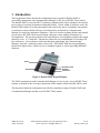
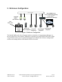
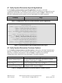
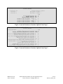
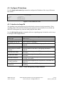
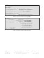
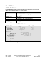
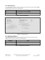
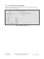
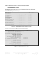
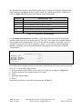
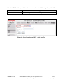
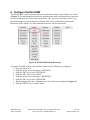
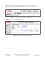
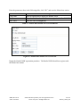
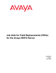
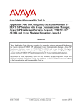
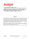
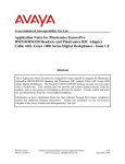
Avaya Solution & Interoperability Test Lab Application Notes for Konftel 300W and Avaya AuraTM Communication Manager – Issue 1.0 Abstract These Application Notes describe the compliance testing of Konftel 300W with Avaya AuraTM Communication Manager. The Konftel 300W is a conference unit which communicates with Communication Manager via the Avaya R4 DECT base station. The compliance testing tested the major functions of the Konftel 300W product. Information in these Application Notes has been obtained through DevConnect compliance testing and additional technical discussions. Testing was conducted via the DevConnect Program at the Avaya Solution and Interoperability Test Lab. MRR; Reviewed: SPOC 8/24/2010 Solution & Interoperability Test Lab Application Notes ©2010 Avaya Inc. All Rights Reserved. 1 of 48 Konftel_300W_CM Table of Contents 1. Introduction ............................................................................................................................. 3 1.1. Interoperability Compliance Testing .............................................................................. 4 1.2. Support ............................................................................................................................ 4 2. Reference Configuration ......................................................................................................... 5 3. Equipment and Software Validated ........................................................................................ 6 4. Configure Avaya AuraTM Communication Manager .............................................................. 6 4.1. Verify System-Parameters Special-Applications ............................................................ 7 4.2. Verify System-Parameters Customer-Options ................................................................ 7 4.3. Configure IP Interfaces ................................................................................................... 9 4.3.1. Interface to Avaya R4 ............................................................................................. 9 4.4. Add Stations .................................................................................................................. 13 4.4.1. Add Mobile Stations ............................................................................................. 13 4.4.2. Add IP Stations ..................................................................................................... 14 4.4.3. Add Analog Stations ............................................................................................. 14 4.4.4. Add Digital Stations .............................................................................................. 15 4.5. Configure Meet-Me Conference ................................................................................... 16 4.5.1. Create Conference Announcements ...................................................................... 17 4.5.2. Configure Meet-Me Conference Vector ............................................................... 20 4.5.3. Configure Meet-Me Conference Vector Directory Number ................................. 20 4.5.4. Configure Meet-Me Conference Access Code Change Feature ........................... 21 5. Configure Avaya R4 Base Stations....................................................................................... 22 5.1. Configure Master Base Station ..................................................................................... 23 5.2. Configure Slave Base Station ....................................................................................... 33 6. Configure Konftel 300W ...................................................................................................... 41 7. General Test Approach and Test Results .............................................................................. 44 8. Verification Steps.................................................................................................................. 44 8.1. Verify Avaya AuraTM Configuration ............................................................................ 44 8.2. Verify Avaya R5 Master Base Station Configuration .................................................. 46 8.3. Verify Konftel 300W Configuration ............................................................................. 46 9. Conclusion ............................................................................................................................ 46 10. Additional References ....................................................................................................... 47 MRR; Reviewed: SPOC 8/24/2010 Solution & Interoperability Test Lab Application Notes ©2010 Avaya Inc. All Rights Reserved. 2 of 48 Konftel_300W_CM 1. Introduction These Application Notes describe the configuration steps required for Konftel 300W to successfully interoperate with Communication Manager via the Avaya R4 DECT base station. The Konftel 300W is a wireless DECT conference endpoint which can be attached to an external power source or run from its internal rechargeable battery. Placed within a conference room, the Konftel 300W enables all of the participants in the room to take part in a telephone conversation. A conference can be initiated with up to two other parties as allowed by Communication Manager for single line appearance telephones. Due to its wireless roaming abilities and internal power source, the 300W can be moved among conference rooms without reconnection or reconfiguration. The unit also performs echo cancellation to avoid feedback problems that might otherwise occur. A “Conference” function key allows the easy establishment of recurring or ad hoc conferences. For conferences with more than three participants, the Communication Manager “meet-me” conference feature can be used. The Konftel 300W has a keypad/display, shown in the figure below, which serves as a telephone keypad, as well as providing additional functions. Menu Hold Off-Hook / Flash On-Hook Conference Figure 1: Konftel 300W Keypad /Display The 300W communicates with Communication Manager via one or more Avaya R4 DECT base stations, as dictated by the coverage requirements of the campus within which the 300W is used. This document details the configuration used for the compliance testing of Konftel 300W with Communication Manager and the Avaya R4 DECT base station. MRR; Reviewed: SPOC 8/24/2010 Solution & Interoperability Test Lab Application Notes ©2010 Avaya Inc. All Rights Reserved. 3 of 48 Konftel_300W_CM 1.1. Interoperability Compliance Testing The compliance testing included the following test scenarios: Registration / De-registration Roaming Basic call (local, external, priority call) Long calls Call waiting and call toggle Hold / retrieve Supervised / blind transfer Ad hoc conference Automatic conference Instant conference Meet-Me conference DTMF Serviceability: automatic startup after power interruption 1.2. Support Support from Avaya is available at http://support.avaya.com/. Support for Konftel products is available at Web-based support: http://www.konftel.com/ Email: [email protected] International help desk: +46 90706489 North American help: +1 866-606-4728. MRR; Reviewed: SPOC 8/24/2010 Solution & Interoperability Test Lab Application Notes ©2010 Avaya Inc. All Rights Reserved. 4 of 48 Konftel_300W_CM 2. Reference Configuration 192.168.150.X .107 CM .202 GW .201 .108 Avaya R4 DECT Base Stations Avaya S8300 Server Avaya G350 Media Gateway Avaya AuraTM Communication Manager PRI Unit Under Test PSTN B A Konftel 300W C D Avaya 3725 Avaya IP DECT Telephone Telephones E F Avaya Digital Avaya Analog Telephone Telephone G Figure 2: Reference Configuration The Konftel 300W in the above diagram interfaces wirelessly to Communication Manager via the Avaya R4 DECT base stations. Although it is possible to use the Konftel 300W with a single Avaya R4 base station, two Avaya R4 base stations are included in the reference configuration, to allow the roaming abilities of the Konftel 300W to be tested. MRR; Reviewed: SPOC 8/24/2010 Solution & Interoperability Test Lab Application Notes ©2010 Avaya Inc. All Rights Reserved. 5 of 48 Konftel_300W_CM The following table contains additional information about how each of the telephones contained in the above diagram are configured in Communication Manager: Diagram A B C D E F G Ext 10302 10304 10172 10062 10202 10001 06911111111 Endpoint Konftel 300W Avaya 3725 DECT Telephone Avaya 9620 IP Telephone Avaya 1608 IP Telephone Avaya 2410 Digital Telephone Avaya 2500 Analog Telephone ISDN endpoint Table 1: Extensions Used for Testing 3. Equipment and Software Validated The following equipment and software were used for the sample configuration provided: Software Component Avaya AuraTM Communication Manager Avaya G350 Media Gateway Avaya G350 Analog Module Avaya 2410 Digital Telephone Avaya 1608 Telephone Avaya 9620 Telephone Avaya 3725 DECT Telephone Avaya R4 DECT Konftel 300W Version R015x.01.2.416.4 30.10.4 HW06/FW093 5.0 1.2.2 3.1.1 3.0.10 Hardware: IPBS1-Y3/PB, IPBS: 3.2.8, Bootcode: 3.0.26 1.7b.XXXX Table 2: Equipment and Versions Validated 4. Configure Avaya AuraTM Communication Manager The configuration and verification operations illustrated in this section were performed using the Communication Manager System Administration Terminal (SAT). Note that the configuration of the interface to the PSTN is out of the scope of these Application Notes. MRR; Reviewed: SPOC 8/24/2010 Solution & Interoperability Test Lab Application Notes ©2010 Avaya Inc. All Rights Reserved. 6 of 48 Konftel_300W_CM 4.1. Verify System-Parameters Special-Applications Use the display system-parameters special-applications command to verify that Communication Manager is configured to meet the minimum requirements to support the special applications used for these tests, as shown by the parameter values in Table 3. If these are not met in the configuration, please contact an Avaya representative for further assistance. Parameter PMS X-Station Mobility over IP Usage The value must be set to “y”. Table 3: Configuration Values for System-Parameters Special-Applications display system-parameters special-applications SPECIAL APPLICATIONS Page (SA8481) - Replace Calling Party Number with ASAI ANI? (SA8500) - Expanded UUI Display Information? (SA8506) - Altura Interoperability (FIPN)? (SA8507) - H245 Support With Other Vendors? (SA8508) - Multiple Emergency Access Codes? (SA8510) - NTT Mapping of ISDN Called-Party Subaddress IE? (SA8517) - Authorization Code By COR? n n n n n n n (SA8520) - Hoteling Application for IP Terminals? (SA8558) - Increase Automatic MWI & VuStats (S8700 only)? (SA8567) - PHS X-Station Mobility over IP? (SA8569) - No Service Observing Tone Heard by Agent? (SA8573) - Call xfer via ASAI on CAS Main? (SA8582) - PSA Location and Display Enhancements? (SA8587) - Networked PSA via QSIG Diversion? (SA8589) - Background BSR Polling? (SA8608) - Increase Crisis Alert Buttons (S8700 only)? (SA8621) - SCH Feature Enhancements? n n y n n n n n n n 4 of 9 Figure 3: System-Parameters Special-Applications Form, Page 4 4.2. Verify System-Parameters Customer-Options Use the display system-parameters customer-options command to verify that Communication Manager is configured to meet the minimum requirements to support the configuration used for these tests, as shown by the parameter values in Table 4. If these are not met in the configuration, please contact an Avaya representative for further assistance. Parameter Usage The value must be sufficient to allow the number of stations, Maximum Stations (Page 1) including the 300W, shown in Table 1. Maximum XMOBILE The value must be sufficient to allow the number of DECT Stations (Page 1) stations, including the 300W, shown in Table 1. Maximum Concurrently The value must be sufficient to allow the number of IP stations, Registered IP Stations (Page 2) including the 300W, shown in Table 1 Table 4: Configuration Values for System-Parameters Customer-Options MRR; Reviewed: SPOC 8/24/2010 Solution & Interoperability Test Lab Application Notes ©2010 Avaya Inc. All Rights Reserved. 7 of 48 Konftel_300W_CM display system-parameters customer-options OPTIONAL FEATURES G3 Version: V15 Location: 2 Platform: 13 Page 1 of 11 Software Package: Standard RFA System ID (SID): 1 RFA Module ID (MID): 1 Maximum Maximum Maximum Maximum Maximum Platform Maximum Ports: Maximum Stations: Maximum XMOBILE Stations: Off-PBX Telephones - EC500: Off-PBX Telephones OPS: Off-PBX Telephones - PBFMC: Off-PBX Telephones - PVFMC: Off-PBX Telephones - SCCAN: 900 450 100 0 100 0 0 0 USED 60 8 0 0 0 0 0 0 Figure 4: System-Parameters Customer-Options Form, Page 1 display system-parameters customer-options OPTIONAL FEATURES Page IP PORT CAPACITIES Maximum Administered H.323 Trunks: Maximum Concurrently Registered IP Stations: Maximum Administered Remote Office Trunks: Maximum Concurrently Registered Remote Office Stations: Maximum Concurrently Registered IP eCons: Max Concur Registered Unauthenticated H.323 Stations: Maximum Video Capable H.323 Stations: Maximum Video Capable IP Softphones: Maximum Administered SIP Trunks: Maximum Administered Ad-hoc Video Conferencing Ports: Maximum Number of DS1 Boards with Echo Cancellation: Maximum TN2501 VAL Boards: Maximum Media Gateway VAL Sources: Maximum TN2602 Boards with 80 VoIP Channels: Maximum TN2602 Boards with 320 VoIP Channels: Maximum Number of Expanded Meet-me Conference Ports: 1000 18000 0 0 0 0 0 0 1000 0 0 10 0 128 128 0 2 of 11 USED 50 5 0 0 0 0 0 0 30 0 0 1 0 0 0 0 Figure 5: System-Parameters Customer-Options Form, Page 2 MRR; Reviewed: SPOC 8/24/2010 Solution & Interoperability Test Lab Application Notes ©2010 Avaya Inc. All Rights Reserved. 8 of 48 Konftel_300W_CM 4.3. Configure IP Interfaces Use the change node-names ip command to configure the IP address of the Avaya R4 master base station. change node-names ip Page 1 of 2 IP NODE NAMES Name default dect procr IP Address 0.0.0.0 192.168.150.107 192.168.150.202 Figure 6: Node-Names IP Form 4.3.1. Interface to Avaya R4 The signaling group and trunk group described in this section are closely interrelated. If the signaling group is allocated first, all trunk group parameters must initially be set to blank and entered in a subsequent step, after the trunk group has been added. Use the add signaling-group command to allocate a signaling group for interface to the Avaya R5 using the following parameters: Parameter Group Type Max number of NCA TSC Max number of CA TSC Trunk Group for NCA TSC X-Mobility/Wireless Type Trunk Group for Channel Selection Near-end Node Name Far-end Node Name Near-end Listen Port Far-end Listen Port Direct IP-IP Audio Connections Usage Enter “h.323”. Enter a value of 1 or greater. Enter a value of 1 or greater. Enter the number of the DECT trunk group allocated in Figure 8. Enter “DECT”. Enter the number of the DECT trunk group allocated in Figure 8. Enter “procr” do designate the G350 processor as the near end node name. Enter “dect” to assign the Avaya R4 base station as the far end node name. Specify an otherwise unused port to be used to listen for incoming voice traffic. Specify the port assigned to the Avaya R4 as “Local Port” in Figure 31. Enter “y” to allow direct IP-IP endpoint connections (shuffling). Table 5: Avaya R4 Signaling-Group Parameters MRR; Reviewed: SPOC 8/24/2010 Solution & Interoperability Test Lab Application Notes ©2010 Avaya Inc. All Rights Reserved. 9 of 48 Konftel_300W_CM add signaling-group 8 Page 1 of 6 SIGNALING GROUP Group Number: 8 Group Type: h.323 Remote Office? n SBS? n Max number of NCA TSC: Max number of CA TSC: Trunk Group for NCA TSC: X-Mobility/Wireless Type: 5 5 8 DECT IP Video? n Trunk Group for Channel Selection: 8 TSC Supplementary Service Protocol: a T303 Timer(sec): 10 H.245 DTMF Signal Tone Duration(msec): Near-end Node Name: procr Far-end Node Name: dect Near-end Listen Port: 5210 Far-end Listen Port: 5210 Far-end Network Region: 1 LRQ Required? n Calls Share IP Signaling Connection? n RRQ Required? n Bypass If IP Threshold Exceeded? n H.235 Annex H Required? n DTMF over IP: out-of-band Direct IP-IP Audio Connections? y Link Loss Delay Timer(sec): 90 IP Audio Hairpinning? n Enable Layer 3 Test? y Interworking Message: PROGress H.323 Station Outgoing Direct Media? n DCP/Analog Bearer Capability: 3.1kHz Figure 7: Avaya R4 Signaling-Group Form MRR; Reviewed: SPOC 8/24/2010 Solution & Interoperability Test Lab Application Notes ©2010 Avaya Inc. All Rights Reserved. 10 of 48 Konftel_300W_CM Use the add trunk-group <n> command, were <n> is an unused trunk number, to allocate a trunk group to be used as an interface to the Avaya R4 Base Station. Use the parameters show in the following table. Parameter Group Type (Page 1) Group Name (Page 1) Usage Enter “isdn”. Assign a name for identification purposes. Enter the Trunk Access Code to be used to identify TAC (Page 1) this trunk. Enter “two-way Direction (Page 1) Enter “H.323”. Carrier Medium (Page 1) Enter “tie”. Service Type (Page 1) Enter “auto”. Member Assignment Method (Page 1) Enter number of the signaling group allocated in Signaling Group (Page 1) Figure 7. Enter a number large enough to support the Number of Members (Page 1) maximum number of anticipated simultaneous calls to be made via the DECT trunk. CONNECT Reliable When Call Leaves ISDN Codeset to Send Display (Page 2) Enter “overlap/enbloc” Digit Handling (in/out) (Page 2) Disconnect Supervision In / Out (Page 2) Enter “y” / “y”. CONNECT Reliable When Call Leaves Enter “n”. ISDN (Page 2) Enter “1”. NCA-TSC Trunk Member (Page 3) Enter “y”. Send Calling Number (Page 3) Enter “unk-pvt” Format (Page 3) Enter “y”. Send Connected Number (Page 3) Table 6: Avaya R4 Trunk-Group Parameters add trunk-group 8 Page 1 of 21 TRUNK GROUP Group Number: Group Name: Direction: Dial Access? Queue Length: Service Type: 8 DECT two-way y 0 tie Group Type: isdn CDR Reports: y COR: 1 TN: 1 TAC: *08 Outgoing Display? n Carrier Medium: H.323 Busy Threshold: 255 Night Service: Auth Code? n Member Assignment Method: auto Signaling Group: 8 Number of Members: 10 Figure 8: Avaya R4 Trunk-Group Form, Page 1 MRR; Reviewed: SPOC 8/24/2010 Solution & Interoperability Test Lab Application Notes ©2010 Avaya Inc. All Rights Reserved. 11 of 48 Konftel_300W_CM add change trunk-group 8 Group Type: isdn Page TRUNK PARAMETERS Codeset to Send Display: 0 Disconnect Supervision - In? y Answer Supervision Timeout: 0 21 Codeset to Send National IEs: 6 Charge Advice: none Digit Handling (in/out): overlap/enbloc Digits: Supplementary Service Protocol: a Digit Treatment: Incoming Calling Number - Delete: 2 of Digital Loss Group: 18 Format: Insert: Out? y CONNECT Reliable When Call Leaves ISDN? n Figure 9: Avaya R4 Trunk-Group Form, Page 2 add trunk-group 8 TRUNK FEATURES ACA Assignment? n Used for DCS? n Suppress # Outpulsing? n Send UUI IE? y Send UCID? n Send Codeset 6/7 LAI IE? y Page Measured: Internal Alert? Data Restriction? Send Name: none n n n 3 of 21 Maintenance Tests? NCA-TSC Trunk Member: Send Calling Number: Send EMU Visitor CPN? y 1 y n Format: unk-pvt UUI IE Treatment: service-provider Replace Restricted Numbers? Replace Unavailable Numbers? Send Connected Number: Hold/Unhold Notifications? Modify Tandem Calling Number? n n y n n Figure 10: Avaya R4 Trunk-Group Form, Page 3 MRR; Reviewed: SPOC 8/24/2010 Solution & Interoperability Test Lab Application Notes ©2010 Avaya Inc. All Rights Reserved. 12 of 48 Konftel_300W_CM 4.4. Add Stations 4.4.1. Add Mobile Stations Use the add station command to add an extension for each of the mobile extensions listed in Table 1 using the parameters shown in the following table. Parameter Usage Enter “XMOBILE” for an analog telephone. Enter an appropriate name to identify the station. Enter “DECT”. Enter the number of the trunk group which allocated in Figure 8 for connection to the Avaya R4 base station. Enter the number allocated to this station. Enter “both”. Enter “12x3”. Type Name XMOBILE Type Mobility Trunk Group Cell Phone Number Mapping Mode Length of Display Table 7: Mobile Station Parameters add station 10301 Page 1 of 4 STATION Extension: 10301 Type: XMOBILE Lock Messages? n Security Code: Coverage Path 1: Coverage Path 2: Hunt-to Station: Name: extn 10301 BCC: TN: COR: COS: 0 1 1 1 STATION OPTIONS Time of Day Lock Table: XMOBILE Type: Display Module? Display Language: Mobility Trunk Group: Configuration Set: DECT y english 8 Message Lamp Ext: Message Waiting Type: Length of Display: Calls Allowed: 10301 ICON 12x3 all CELL PHONE NUMBER MAPPING Dial Prefix: Cell Phone Number: 10301 Mapping Mode: both Figure 11: Mobile Station Form MRR; Reviewed: SPOC 8/24/2010 Solution & Interoperability Test Lab Application Notes ©2010 Avaya Inc. All Rights Reserved. 13 of 48 Konftel_300W_CM 4.4.2. Add IP Stations Use the add station command to add an extension for each of the IP extensions listed in Table 1 using the parameters shown in the following table. Parameter Usage Enter endpoint type as shown in Table 1. Enter an appropriate name to identify the station. Enter an appropriate security code for the station. Type Name Security Code Table 8: IP Station Parameters add station 10172 Page 1 of 5 STATION Extension: Type: Port: Name: 10172 9620 S00006 extn 10172 Lock Messages? n Security Code: 123456 Coverage Path 1: Coverage Path 2: Hunt-to Station: BCC: TN: COR: COS: 0 1 1 1 STATION OPTIONS Loss Group: 19 Speakerphone: Display Language: Survivable GK Node Name: Survivable COR: Survivable Trunk Dest? 2-way english internal y Time of Day Lock Table: Personalized Ringing Pattern: 1 Message Lamp Ext: 10172 Mute Button Enabled? y Media Complex Ext: IP SoftPhone? n Customizable Labels? y Figure 12: IP Station Form 4.4.3. Add Analog Stations Use the add station command to add an extension for each of the room extensions listed in Table 1 using the parameters shown in the following table. Parameter Type Port Name Usage Enter “2500” for an analog telephone. Enter the address of the port to which the telephone is attached. Enter an appropriate name to identify the station. Table 9: Analog Station Parameters MRR; Reviewed: SPOC 8/24/2010 Solution & Interoperability Test Lab Application Notes ©2010 Avaya Inc. All Rights Reserved. 14 of 48 Konftel_300W_CM add station 10202 Page 1 of 4 STATION Extension: Type: Port: Name: 10202 2500 001V702 extn 10202 Lock Messages? n Security Code: Coverage Path 1: Coverage Path 2: Hunt-to Station: STATION OPTIONS XOIP Endpoint type: auto Loss Group: 1 Off Premises Station? n BCC: TN: COR: COS: Tests? 0 1 1 1 y Time of Day Lock Table: Message Waiting Indicator: none Survivable COR: internal Survivable Trunk Dest? y Figure 13: Analog Station Form 4.4.4. Add Digital Stations Use the add station command to add an extension for each of the room extensions listed in Table 1 using the parameters shown in the following table. Parameter Usage Enter endpoint type as shown in Table 1. Enter the address of the port to which the telephone is attached. Enter an appropriate name to identify the station. Type Port Name Table 10: Mobile Station Parameters add station 10001 Page 1 of 5 STATION Extension: Type: Port: Name: 10001 2410 001V301 extn 10001 Lock Messages? n Security Code: Coverage Path 1: Coverage Path 2: Hunt-to Station: BCC: TN: COR: COS: 0 1 1 1 STATION OPTIONS Loss Group: 2 Speakerphone: 2-way Display Language: english Survivable COR: internal Survivable Trunk Dest? y Time of Day Lock Table: Personalized Ringing Pattern: 1 Message Lamp Ext: 10001 Mute Button Enabled? y Media Complex Ext: IP SoftPhone? n Customizable Labels? y Figure 14: Mobile Room Station Form MRR; Reviewed: SPOC 8/24/2010 Solution & Interoperability Test Lab Application Notes ©2010 Avaya Inc. All Rights Reserved. 15 of 48 Konftel_300W_CM 4.5. Configure Meet-Me Conferencing Since Communication Manager limits single line-appearance endpoints to initiating conferences with a maximum of two other participants, a “meet-me” conference can optionally be established if more that this number of participants is required. Use of this feature requires that “Enhanced Conferencing” be included in the feature set, as indicated by the “system-parameters customeroptions” form. Furthermore, the “Maximum Media Gateway VAL Sources” configuration value must be sufficient to allow the Media Gateway to serve as a source of announcements. If these requirements are not met in the configuration, please contact an Avaya representative for further assistance. display system-parameters customer-options OPTIONAL FEATURES Page IP PORT CAPACITIES Maximum Administered H.323 Trunks: Maximum Concurrently Registered IP Stations: Maximum Administered Remote Office Trunks: Maximum Concurrently Registered Remote Office Stations: Maximum Concurrently Registered IP eCons: Max Concur Registered Unauthenticated H.323 Stations: Maximum Video Capable H.323 Stations: Maximum Video Capable IP Softphones: Maximum Administered SIP Trunks: Maximum Administered Ad-hoc Video Conferencing Ports: Maximum Number of DS1 Boards with Echo Cancellation: Maximum TN2501 VAL Boards: Maximum Media Gateway VAL Sources: Maximum TN2602 Boards with 80 VoIP Channels: Maximum TN2602 Boards with 320 VoIP Channels: Maximum Number of Expanded Meet-me Conference Ports: 100 450 0 0 0 0 0 0 100 0 0 0 10 0 0 0 2 of 11 USED 10 2 0 0 0 0 0 0 15 0 0 0 1 0 0 0 Figure 15: System-Parameters Customer-Options Form, Page 2 display system-parameters customer-options OPTIONAL FEATURES Emergency Access to Attendant? Enable 'dadmin' Login? Enhanced Conferencing? Enhanced EC500? Enterprise Survivable Server? Enterprise Wide Licensing? ESS Administration? Extended Cvg/Fwd Admin? External Device Alarm Admin? Five Port Networks Max Per MCC? Flexible Billing? Forced Entry of Account Codes? Global Call Classification? Hospitality (Basic)? Hospitality (G3V3 Enhancements)? IP Trunks? y y y y n n n y n n n n n y y y Page 4 of 11 IP Stations? y ISDN Feature Plus? ISDN/SIP Network Call Redirection? ISDN-BRI Trunks? ISDN-PRI? Local Survivable Processor? Malicious Call Trace? Media Encryption Over IP? Mode Code for Centralized Voice Mail? n n y y n n n n Multifrequency Signaling? Multimedia Call Handling (Basic)? Multimedia Call Handling (Enhanced)? Multimedia IP SIP Trunking? y n n n IP Attendant Consoles? n Figure 16: System-Parameters Customer-Options Form, Page 4 MRR; Reviewed: SPOC 8/24/2010 Solution & Interoperability Test Lab Application Notes ©2010 Avaya Inc. All Rights Reserved. 16 of 48 Konftel_300W_CM 4.5.1. Create Conference Announcements Configure the announcement facility of the media gateway by entering the parameters shown below for port V9 of the media gateway. change media-gateway 1 Page 1 of 1 MEDIA GATEWAY Number: Type: Name: Serial No: Encrypt Link? Network Region: 1 g350 G350 06IS48006975 y 1 Location: 1 Registered? FW Version/HW Vintage: MGP IP Address: Controller IP Address: MAC Address: y 30 .10 .4 /3 192.168.150.201 192.168.150.202 00:04:0d:f1:f8:31 Site Data: Recovery Rule: none Slot V1: V2: V3: V4: V5: V6: V7: V8: V9: Module Type S8300 MM720 MM712 MM710 MM710 MM314 1T+2L-Integ-Analog Name ICC MM BRI MM DCP MM DS1 MM DS1 MM ETH 24P MM ANA IMM gateway-announcements ANN VMM Max Survivable IP Ext: 8 Figure 17: Media-Gateway Form MRR; Reviewed: SPOC 8/24/2010 Solution & Interoperability Test Lab Application Notes ©2010 Avaya Inc. All Rights Reserved. 17 of 48 Konftel_300W_CM Enable the announcement facility by entering the following command: enable announcement-board v9 Announcements can be created from an Avaya IP station which has a COS which has the Console Permissions parameter set to “y”. change change cos CLASS OF SERVICE Page Auto Callback Call Fwd-All Calls Data Privacy Priority Calling Console Permissions Off-hook Alert Client Room Restrict Call Fwd-Off Net Call Forwarding Busy/DA Personal Station Access (PSA) Extended Forwarding All Extended Forwarding B/DA Trk-to-Trk Transfer Override QSIG Call Offer Originations Contact Closure Activation 0 n n n n n n n y n n n n n n n 1 y y y y y n y y y n n n n n n 2 y y y y n n n y y n n n n n n 3 y y y y y n y y n n n n n n n 4 y y n n n n n y n n n n n n n 5 n n y n n n n y n n n n n n n 6 y n y n n n n y n n n n n n n 7 n y y n n n n y n n n n n n n 8 y y y n n n n y n n n n n n n 1 of 2 9 10 11 12 13 14 15 n y n y n y n n n y y n n y n n n n y y y y y y y y y y n n n n n n n n n n n n n n n n n n n n n y y y y y y y n n n n n n n n n n n n n n n n n n n n n n n n n n n n n n n n n n n n n n n n n n n n n n n n n Figure 18: Announcement Creation Station COS Form A Feature Access code must be allocated to create an announcement. change feature-access-codes Page FEATURE ACCESS CODE (FAC) Abbreviated Dialing List1 Access Code: Abbreviated Dialing List2 Access Code: Abbreviated Dialing List3 Access Code: Abbreviated Dial - Prgm Group List Access Code: Announcement Access Code: #01 Answer Back Access Code: Attendant Access Code: Auto Alternate Routing (AAR) Access Code: Auto Route Selection (ARS) - Access Code 1: 0 Access Code 2: Automatic Callback Activation: Deactivation: Call Forwarding Activation Busy/DA: All: Deactivation: Call Forwarding Enhanced Status: Act: Deactivation: Call Park Access Code: Call Pickup Access Code: CAS Remote Hold/Answer Hold-Unhold Access Code: CDR Account Code Access Code: Change COR Access Code: Change Coverage Access Code: Conditional Call Extend Activation: Deactivation: Contact Closure Open Code: Close Code: 1 of 8 Figure 19: Announcement Access Code MRR; Reviewed: SPOC 8/24/2010 Solution & Interoperability Test Lab Application Notes ©2010 Avaya Inc. All Rights Reserved. 18 of 48 Konftel_300W_CM The announcements shown in the following table must be created, by dialing the announcement access code shown in Figure 19 from a station which has “console permissions” enabled in its COS (see Figure 18), and speaking each announcement at the prompt. Extension 3921 3922 3923 3924 3925 3926 Announcement Text “Welcome to the conference, please enter your conference code” “Please re-enter your conference code” “Your conference code was not recognized” “Your are the first member of the conference” “The conference capacity has been exhausted” “There are already participants logged into the conference” Table 11: Conference Announcements Use the change announcements command to create announcement records on the physical medium, in this case the Avaya media gateway. The “Ext” value used is the extension which is to be assigned to the announcement. This can be any unused extension. Assign the “Type” to “integrated”. Any text value can be assigned to “Name”, as it is only used for informational purposes. The media gateway integrated announcement interface port should be assigned to “Group/Board”. add announcement 3921 Page 1 of 1 ANNOUNCEMENTS/AUDIO SOURCES Extension: Annc Name: Annc Type: Group/Board: Protected? 3921 welcome integrated 001V9 n COR: 1 TN: 1 Queue? y Rate: 64 Record the required announcements from the station which has the COS with console permission (Ext. 10172) via the following procedure: Dial the Announcement feature access code (#01), which was configured in Figure 19. Dial the extension of the announcement to be created. Dial 1 Speak the announcement Dial # Repeat this procedure for each of the announcements in Table 11. MRR; Reviewed: SPOC 8/24/2010 Solution & Interoperability Test Lab Application Notes ©2010 Avaya Inc. All Rights Reserved. 19 of 48 Konftel_300W_CM 4.5.2. Configure Meet-Me Conference Vector Enter the change vector <n> command, where n is an unused vector using the parameters shown in the following form. The content of each of the announcements is shown in Table 11. change vector 3 Page 1 of 6 CALL VECTOR Number: 3 Name: conference Meet-me Conf? y Lock? y Basic? y EAS? y G3V4 Enhanced? y ANI/II-Digits? y ASAI Routing? y Prompting? y LAI? n G3V4 Adv Route? y CINFO? y BSR? y Holidays? y Variables? y 3.0 Enhanced? y 01 collect 6 digits after announcement 3921 02 goto step 6 if digits = meet-me-access 03 collect 6 digits after announcement 3922 04 goto step 6 if digits = meet-me-access 05 disconnect after announcement 3923 06 goto step 11 if meet-me-idle 07 goto step 14 if meet-me-full 08 announcement 3926 09 route-to meetme 10 stop 11 announcement 3924 12 route-to meetme 13 stop 14 disconnect after announcement 3925 Figure 20: Meet-Me Conference Vector Form 4.5.3. Configure Meet-Me Conference Vector Directory Number Enter the add vdn <n> command, where n is an unused extension using the parameters shown in the following table. Parameter Extension Name Destination Meet-me Conferencing Conference Access Code Conference Controller Usage Enter an unused extension contained within the dial plan. Enter an appropriate name to identify the station. Enter the vector number to be used for the conference, defined in Figure 20. Enter “y”. Enter an appropriate code to be used for the authorization of conference participants. Enter the extension of the station which controls the conference. This can be the extension of the Konftel 300W. This station has the ability to change the Conference Access code. Table 12: Meet-Me Conference Vector Directory Number Parameters MRR; Reviewed: SPOC 8/24/2010 Solution & Interoperability Test Lab Application Notes ©2010 Avaya Inc. All Rights Reserved. 20 of 48 Konftel_300W_CM add vdn 11003 Page 1 of 3 VECTOR DIRECTORY NUMBER Extension: 11003 Name: Conference Destination: Vector Number 3 Meet-me Conferencing? y COR: 1 TN: 1 Figure 21: Meet-Me Conference Vector Directory Number Form, Page 1 add vdn 11003 Page 2 of 3 VECTOR DIRECTORY NUMBER MEET-ME CONFERENCE PARAMETERS: Conference Access Code: 123456 Conference Controller: 10302 Conference Type: 6-party Figure 22: Meet-Me Conference Vector Directory Number Form, Page 2 4.5.4. Configure Meet-Me Conference Access Code Change Feature Enter the change feature-access-codes command to configure the feature access code to be used to change the conference access code. change feature-access-codes Page FEATURE ACCESS CODE (FAC) Leave Word Calling Send A Message: Leave Word Calling Cancel A Message: Limit Number of Concurrent Calls Activation: Deactivation: Malicious Call Trace Activation: Deactivation: Meet-me Conference Access Code Change: *60 Message Sequence Trace (MST) Disable: PASTE (Display PBX data on Phone) Access Personal Station Access (PSA) Associate Per Call CPN Blocking Code Access Per Call CPN Unblocking Code Access Code: Code: Code: Code: 3 of 8 Dissociate Code: Priority Calling Access Code: Program Access Code: Refresh Terminal Parameters Access Code: Remote Send All Calls Activation: Self Station Display Activation: Send All Calls Activation: Station Firmware Download Access Code: Deactivation: Deactivation: Figure 23: Meet-Me Conference Access Code Change Sequence MRR; Reviewed: SPOC 8/24/2010 Solution & Interoperability Test Lab Application Notes ©2010 Avaya Inc. All Rights Reserved. 21 of 48 Konftel_300W_CM 5. Configure Avaya R4 Base Stations Although it is possible to use the Konftel 300W with a single Avaya R4 base station, two Avaya R4 base stations are included in the reference configuration, to allow the roaming abilities of the Konftel 300W to be tested. In its un-configured state, the Avaya R4 base station is set to be a DHCP client. Thus, the MAC address of each base station to be included in the configuration should be entered into the DHCP server together with the IP address, network mask, and default gateway address which are to be assigned to that base station. The Avaya R4 base stations have an integrated HTTP server which allows the input of configuration parameters via a web browser. Each Avaya R4 base station consists of two independent components: A PBX interface component which has a trunk interface to the PBX and an IP interface to one or more radio components. A radio component which interfaces to the wireless endpoints via DECT and via IP interface to a Master base station containing an active PBX interface component. The unit which serves as Master has an active PBX interface component and can also have an active radio component. Any additional base stations, hereafter referred to as Slave base stations, can extend radio coverage. Each has an active radio component which communicates with the Master via IP, and an inactive PBX interface component. MRR; Reviewed: SPOC 8/24/2010 Solution & Interoperability Test Lab Application Notes ©2010 Avaya Inc. All Rights Reserved. 22 of 48 Konftel_300W_CM 5.1. Configure Master Base Station Enter the URL of the master base station into a web browser and select the “System administration” control. Figure 24: Master Base Selection Enter the appropriate credentials and click “OK”. For the first-time login, the default password is “changeme”. After initial login, this should be changed to an appropriate value, for security reasons. Figure 25: Master Base Station Login MRR; Reviewed: SPOC 8/24/2010 Solution & Interoperability Test Lab Application Notes ©2010 Avaya Inc. All Rights Reserved. 23 of 48 Konftel_300W_CM The initial display shows the General->Info tab, which contains version/hardware identification information. Figure 26: Master Base Station General -> Info Tab MRR; Reviewed: SPOC 8/24/2010 Solution & Interoperability Test Lab Application Notes ©2010 Avaya Inc. All Rights Reserved. 24 of 48 Konftel_300W_CM Select the LAN->IP tab. Verify that the IP parameters assigned to the base station correspond to those which are configured in the DHCP reservation. Figure 27: Master Base Station LAN -> IP Tab MRR; Reviewed: SPOC 8/24/2010 Solution & Interoperability Test Lab Application Notes ©2010 Avaya Inc. All Rights Reserved. 25 of 48 Konftel_300W_CM Select the General->Admin tab. Enter the parameters shown in the following table and click “OK”. Parameter Device Name User Name Password Usage Enter an appropriate name to identify the master base station. Enter “admin”, the default administrator user name. Enter an appropriate password. Table 13: Master Base Station General -> Admin Tab Parameters Figure 28: Master Base Station General -> Admin Tab MRR; Reviewed: SPOC 8/24/2010 Solution & Interoperability Test Lab Application Notes ©2010 Avaya Inc. All Rights Reserved. 26 of 48 Konftel_300W_CM Select the DECT->Master tab Enter the parameters shown in the following table and click “OK”. Parameter Mode PBX Protocol Usage Select “Active” from the drop-down menu. Select “ACM” from the drop-down menu. Select “H.323/XMobile” from the drop-down menu. Table 14: Master Base Station DECT -> Master Tab Parameters Figure 29: Master Base Station DECT -> Master Tab MRR; Reviewed: SPOC 8/24/2010 Solution & Interoperability Test Lab Application Notes ©2010 Avaya Inc. All Rights Reserved. 27 of 48 Konftel_300W_CM Select the DECT -> System tab. Enter the parameters shown in the following table and click “OK”. Parameter System Name Password / Confirm Subscriptions Authentication Code Frequency Coder Frame (ms) Usage Enter an appropriate name to identify this base station. Enter an appropriate password for this base station. Select “With System AC” from the drop-down menu. Enter an appropriate code to be used by endpoints for registration authentication. Select “Europe” from the drop-down menu. Select “G711A” from the drop-down menu. Select “20” from the drop-down menu. Table 15: Master Base Station DECT -> System Tab Parameters Figure 30: Master Base Station DECT -> System Tab MRR; Reviewed: SPOC 8/24/2010 Solution & Interoperability Test Lab Application Notes ©2010 Avaya Inc. All Rights Reserved. 28 of 48 Konftel_300W_CM Select the DECT->Trunks tab. Enter the parameters shown in the following table and click “OK”. Parameter Name Local Port CS IP Address CS Port Usage Enter an appropriate name to identify this trunk. Enter the number of the local port which is read by this base station. This must be the same values assigned to “Far-end Listen Port” in Figure 7. Enter the IP assigned to the proc interface in Figure 6. Enter the number of the local port which is read by this base station. This must be the same values assigned to “Near-end Listen Port” in Figure 7. Table 16: Master Base Station DECT -> Trunks Tab Parameters Figure 31: Master Base Station DECT -> Trunks Tab MRR; Reviewed: SPOC 8/24/2010 Solution & Interoperability Test Lab Application Notes ©2010 Avaya Inc. All Rights Reserved. 29 of 48 Konftel_300W_CM Select the DECT->Radio tab. Enter the parameters shown in the following table and click “OK”. Parameter Name Password Master IP Address Usage Enter the System Name assigned to this base station in Figure 30. Enter the password assigned to this base station in Figure 30. Enter the IP address assigned to this base station, as displayed by the “Active Settings” in Figure 27. Table 17: Master Base Station DECT -> Radio Tab Parameters Figure 32: Master Base Station DECT -> Radio Tab MRR; Reviewed: SPOC 8/24/2010 Solution & Interoperability Test Lab Application Notes ©2010 Avaya Inc. All Rights Reserved. 30 of 48 Konftel_300W_CM Select the DECT->Air Sync tab. Enter the parameters shown in the following table, click “OK”. Parameter Sync Mode Usage Select “Master” from the drop-down menu. Table 18: Master Base Station DECT -> Air Sync Tab Parameters Figure 33: Master Base Station DECT -> Air Sync Tab MRR; Reviewed: SPOC 8/24/2010 Solution & Interoperability Test Lab Application Notes ©2010 Avaya Inc. All Rights Reserved. 31 of 48 Konftel_300W_CM Select the Reset->Idle-Reset tab. Click “OK”. Figure 34: Master Base Station Reset -> Idle-Reset Tab MRR; Reviewed: SPOC 8/24/2010 Solution & Interoperability Test Lab Application Notes ©2010 Avaya Inc. All Rights Reserved. 32 of 48 Konftel_300W_CM 5.2. Configure Slave Base Station Enter the URL of the slave base station into a web browser and select the “System Administration” control. Figure 35: Slave Base Selection Enter the appropriate credentials and click “OK”. For the first-time login, the default password is “changeme”. Figure 36: Slave Base Station Login MRR; Reviewed: SPOC 8/24/2010 Solution & Interoperability Test Lab Application Notes ©2010 Avaya Inc. All Rights Reserved. 33 of 48 Konftel_300W_CM The initial display shows the General->Info tab, which contains version/hardware identification information. Figure 37: Slave Base Station General -> Info Tab MRR; Reviewed: SPOC 8/24/2010 Solution & Interoperability Test Lab Application Notes ©2010 Avaya Inc. All Rights Reserved. 34 of 48 Konftel_300W_CM Select the LAN->IP tab. Verify that the IP parameters assigned to the base station correspond to those which are configured in the DHCP reservation. . Figure 38: Slave Base Station LAN -> IP Tab MRR; Reviewed: SPOC 8/24/2010 Solution & Interoperability Test Lab Application Notes ©2010 Avaya Inc. All Rights Reserved. 35 of 48 Konftel_300W_CM Select the General->Admin tab Enter the parameters shown in the following table and click “OK”. Parameter Device Name User Name Password Usage Enter an appropriate name to identify the slave base station. Enter “admin”, the default administrator user name. Enter an appropriate password. Table 19: Slave Base Station General -> Admin Tab Parameters Figure 39: Slave Base Station General -> Admin Tab MRR; Reviewed: SPOC 8/24/2010 Solution & Interoperability Test Lab Application Notes ©2010 Avaya Inc. All Rights Reserved. 36 of 48 Konftel_300W_CM Select the DECT->Master tab Enter the parameters shown in the following table and click “ok”. Parameter Mode Usage Select “Off” from the drop-down menu. Table 20: Slave Base Station DECT -> Master Tab Parameters Figure 40: Slave Base Station DECT -> Master Tab MRR; Reviewed: SPOC 8/24/2010 Solution & Interoperability Test Lab Application Notes ©2010 Avaya Inc. All Rights Reserved. 37 of 48 Konftel_300W_CM Select the DECT -> System tab. Enter the parameters shown in the following table and click “ok”. Parameter Name Password Master IP Address Usage Enter the System Name assigned to the master base station in Figure 30. Enter the password assigned to the master base station in Figure 30. Enter the IP address assigned to the master base station, as displayed by the “Active Settings” in Figure 27. Table 21: Slave Base Station DECT -> Radio Tab Parameters Figure 41: Slave Base Station DECT -> Radio Tab MRR; Reviewed: SPOC 8/24/2010 Solution & Interoperability Test Lab Application Notes ©2010 Avaya Inc. All Rights Reserved. 38 of 48 Konftel_300W_CM Select the DECT ->Air-Sync tab Enter the parameters shown in the following table, click “ok”. Parameter Sync Mode Usage Select “Backup-Master” from the drop-down menu. Table 22: Slave Base Station DECT -> Air Sync Tab Parameters Figure 42: Slave Base Station DECT -> Air Sync Tab MRR; Reviewed: SPOC 8/24/2010 Solution & Interoperability Test Lab Application Notes ©2010 Avaya Inc. All Rights Reserved. 39 of 48 Konftel_300W_CM Select the Reset->Idle-Reset tab and click “OK”. Figure 43: Slave Base Station Reset -> Idle-Reset Tab MRR; Reviewed: SPOC 8/24/2010 Solution & Interoperability Test Lab Application Notes ©2010 Avaya Inc. All Rights Reserved. 40 of 48 Konftel_300W_CM 6. Configure Konftel 300W The Konftel 300W can be registered with an Avaya R4 base station via the “Menu” key shown in Figure 1. The initial depression of this key initiates menu mode, which provides access to the top level of the menu tree shown in the figure below. The “up arrow” and “down arrow” keys provide navigation at a given menu level, and the “OK” key descends into a menu branch. Depression of the “Menu” key while within the menu tree cancels menu mode. Figure 44: Konftel 300W Menu Hierarchy To register the 300W with an Avaya R4 base station, use the following key sequence: Press the “Menu” key. Push the “down” key to navigate to “SETTINGS”. Push the “OK” key to select “SETTINGS”. Push the “OK” key to select “DECT”. Push the “down” key to navigate to “REGISTER”. Push the “OK” key to select “REGISTER”. When prompted, enter the “Authentication Code” which was configured in Figure 30. Push the “MENU” key to exit the menu. MRR; Reviewed: SPOC 8/24/2010 Solution & Interoperability Test Lab Application Notes ©2010 Avaya Inc. All Rights Reserved. 41 of 48 Konftel_300W_CM After the initial registration attempt, the Master base station will create an entry in its “Anonymous” user table. Note this entry and then click “Delete” and navigate to the “Users” tab. Figure 45: Master Base Station Users -> Anonymous Tab Navigate to the Users -> Users tab and click “new”. Figure 46: Master Base Station Users -> Users Tab MRR; Reviewed: SPOC 8/24/2010 Solution & Interoperability Test Lab Application Notes ©2010 Avaya Inc. All Rights Reserved. 42 of 48 Konftel_300W_CM Enter the parameters show in the following table, click “OK”, and reset the Master base station. Parameter Long Name Number IPEI / IPDI Usage Enter an appropriate to identify the Konftel 300W. Enter the extension from Table 1 to be assigned to the Konftel 300W. Enter the code from Figure 45. Table 23: Master Base Station New User Parameters Figure 47: Master Base Station New User Screen Repeat the Konftel 300W registration procedure. The Konftel 300W should now register with the Master base station. MRR; Reviewed: SPOC 8/24/2010 Solution & Interoperability Test Lab Application Notes ©2010 Avaya Inc. All Rights Reserved. 43 of 48 Konftel_300W_CM 7. General Test Approach and Test Results The compliance testing of Konftel 300W interoperating with Communication Manager was performed manually. The tests were functional in nature, and no performance testing was done. The following issues were encountered during testing: 1. Although the Konftel 300W automatic conference feature allows conferences to be created with up to five participants, Communication Manager restricts single line appearance telephones, such as the Konftel 300W, to create conferences with a maximum of two other participants. Alternatively, the Communication Manager “meet-me” conference feature described in section 4.5 can be used to establish conferences with up to six participants. 2. It is not possible to un-register the Konftel 300W from the DECT base station using the “De-register” function: the Konftel 300W responds with “NOT SUPPORTED” when this feature is selected. With the exception of the above-described problems, all tests which were performed produced the expected result. Section 1.1 contains a list of tests which were performed. 8. Verification Steps The correct installation and configuration of 300W can be verified by performing the steps shown below. 8.1. Verify Avaya AuraTM Configuration Enter the “status signaling-group” command from the Communication Manager SAT terminal and verify that the signaling group is in the “in-service” state. status signaling-group 8 STATUS SIGNALING GROUP Group ID: Group Type: Signaling Type: Group State: 8 h.323 facility associated signaling in-service Active NCA-TSC Count: 0 Active CA-TSC Count: 0 Figure 48: Signaling Group Status MRR; Reviewed: SPOC 8/24/2010 Solution & Interoperability Test Lab Application Notes ©2010 Avaya Inc. All Rights Reserved. 44 of 48 Konftel_300W_CM Enter the “status trunk” command from the Communication Manager SAT terminal and verify that the all of the trunk members are in the “in-service/idle” state. status trunk 8 TRUNK GROUP STATUS Member Port Service State Mtce Connected Ports Busy 0008/001 0008/002 0008/003 0008/004 0008/005 0008/006 0008/007 0008/008 0008/009 0008/010 T00019 T00020 T00021 T00022 T00023 T00024 T00025 T00026 T00027 T00028 in-service/idle in-service/idle in-service/idle in-service/idle in-service/idle in-service/idle in-service/idle in-service/idle in-service/idle in-service/idle no no no no no no no no no no Figure 49: Trunk Status If meet-me conferencing has been configured, the configuration can be verified by changing the conference access code from the Konftel 300W, by performing the following steps from the Konftel 300W: Dial Sequence Dial the Meet-me Conference Feature Access Code defined in Figure 23 Dial the conference bridge VDN defined in Figure 21 followed by “#”. Dial the current Access Code defined in Figure 22 followed by “#”. Dial the Access Code followed by “#”. Dial NEW Access Code again followed by “#”. Response Dial tone Silence Dial tone Dial tone Confirmation tone Table 24: Dial Sequence for Changing Conference Access Code MRR; Reviewed: SPOC 8/24/2010 Solution & Interoperability Test Lab Application Notes ©2010 Avaya Inc. All Rights Reserved. 45 of 48 Konftel_300W_CM 8.2. Verify Avaya R5 Master Base Station Configuration From the Avaya R4 DECT base station, the Device Overview -> Radios tab should show registrations for the both the Master and Slave base stations. Figure 50: Master Base Station Radio Status 8.3. Verify Konftel 300W Configuration To verify that the Konftel 300W is registered with one of the Avaya R4 base stations: Press the “Menu” key. Push the “down” key repeatedly to navigate to “STATUS”. Push the “OK” key to select “STATUS”. Push the “down” key repeatedly to navigate to “IPEI/PARK” Verify that the first seven digits of the PARK are identical to the first seven digits of master base station SARI. Figure 51: Master Base Station SARI 9. Conclusion These Application Notes contain instructions for configuring a solution with Communication Manager, the Konftel 300W, and the Avaya R4 base stations. A list of instructions is provided to enable the user to verify that the various components have been correctly configured. MRR; Reviewed: SPOC 8/24/2010 Solution & Interoperability Test Lab Application Notes ©2010 Avaya Inc. All Rights Reserved. 46 of 48 Konftel_300W_CM 10. Additional References This section references documentation relevant to these Application Notes. The Avaya product documentation is available at http://support.avaya.com. [1] Administering Avaya Aura™ Communication Manager, January 2009, Document Number 03-300509. [2] Avaya Aura™ Communication Manager Feature Description and Implementation, May 2009, Document Number 555-245-205. [3] Avaya DECT R4 Installation and Administration Manual, August 2009, Document Number 21-603363. [4] Konftel 300W Quick Reference Guide: 110090-61-001, Rev 1b MRR; Reviewed: SPOC 8/24/2010 Solution & Interoperability Test Lab Application Notes ©2010 Avaya Inc. All Rights Reserved. 47 of 48 Konftel_300W_CM ©2010 Avaya Inc. All Rights Reserved. Avaya and the Avaya Logo are trademarks of Avaya Inc. All trademarks identified by ® and ™ are registered trademarks or trademarks, respectively, of Avaya Inc. All other trademarks are the property of their respective owners. The information provided in these Application Notes is subject to change without notice. The configurations, technical data, and recommendations provided in these Application Notes are believed to be accurate and dependable, but are presented without express or implied warranty. Users are responsible for their application of any products specified in these Application Notes. Please e-mail any questions or comments pertaining to these Application Notes along with the full title name and filename, located in the lower right corner, directly to the Avaya DevConnect Program at [email protected]. MRR; Reviewed: SPOC 8/24/2010 Solution & Interoperability Test Lab Application Notes ©2010 Avaya Inc. All Rights Reserved. 48 of 48 Konftel_300W_CM