1
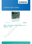
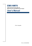
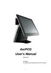
EPC-CDD Fanless Intel® Atom™ Cedar Trail Tiny Box PC with Intel® D2550 + NM10 Chipset Quick Reference Guide 1st Ed – 19 February 2013 Copyright Notice Copyright 2013 Avalue Technology Inc., ALL RIGHTS RESERVED. Part No. E2017EPCCA0R EPC-CDD 1. Getting Started 1.1 Safety Precautions Warning! Always completely disconnect the power cord from your chassis whenever you work with the hardware. Do not make connections while the power is on. Sensitive electronic components can be damaged by sudden power surges. Only experienced electronics personnel should open the PC chassis. Caution! Always ground yourself to remove any static charge before touching the CPU card. Modern electronic devices are very sensitive to static electric charges. As a safety precaution, use a grounding wrist strap at all times. Place all electronic components in a static-dissipative surface or static-shielded bag when they are not in the chassis. 1.2 Packing List Before you begin installing your single board, please make sure that the following materials have been shipped: 1 x EPC-CDD Fanless Intel® Atom™ Cedar Trail Tiny Box PC with Intel® D2550 + NM10 Chipset 1 x Quick Reference Guide 1 x DVD-ROM contains the followings: — User’s Manual (this manual in PDF file) — Ethernet driver and utilities — VGA drivers and utilities — Audio drivers and utilities — WiFi drivers and utilities — Chipset drivers and utilities — CIR drivers and utilities Other major components include the followings: — Adapter X 1 — Antenna X 1 — Wall mount X 1 — Power cord X 1 — Screws 2 EPC-CDD Quick Reference Guide Quick Reference Guide 1.3 System Specifications Specifications System CPU Onboard Intel® Atom™ Processor D2550 (1M Cache, 1.86 GHz) BIOS AMI 16MBit SPI BIOS System Chipset I/O Chip System Memory Storage Watchdog Timer H/W Status Monitor Expansion Intel® NM10 Nuvoton NCT5577D One 204-pin DDR3 1066/1333MHZ SO-DIMM socket, supports up to 4GB Max Support 2.5” Driver Bay Reset: 1sec. ~ 65535sec./min. and 1sec. or 1min./step Monitoring temperature, voltage, and cooling fan status. Auto throttling control when CPU overheats 1x Mini PCI-e socket *Mini PCI-e and m-SATA switch through Jumper External I/O USB port 3 x USB 2.0/1.1 Type A connectors COM port 1 x RS-232 port (Pin 9 without power) LAN port 1 x RJ45 VGA port 1 x VGA HDMI port 1 x HDMI SD card Audio port DC Jack WiFi 1 x SD/SDHC card socket Line-in , Mic-in 1 x DC Jack 2.5mm 1 x Antenna & 802.11 b/g/n WiFi card 1 x Power on/off with Power LED button Others 1 x HDD LED 1 x CIR Display Chipset Resolution Dual Display Integrated Intel® Graphics Media Accelerator VGA /HDMI Display: 1920 x1200 VGA+HDMI Audio Audio Codec Audio Interface Realtek ALC661 HD Audio Decoding controller Mic-in ,Line out Ethernet LAN Chip Ethernet Interface 1x Realtek RT8111E PCIe Gigabit Ethernet 10 /100 /1000 Base-Tx Gigabit Ethernet EPC-CDD Quick Reference Guide 3 EPC-CDD SIM card SIM card 1x SIM Card socket (Internal) SD card socket SD card socket Realtek RTS5138 USB card reader controller support SD/SDHC card Environment &Mechanical Power Type Operating Temp. Storage Temp Operating Humidity Size (L x W) Weight 4 12V 5A 60W adapter 0 ~ 40°C (32 ~ 140°F) (w/HDD), Ambient w/Air Flow -40 ~ 75°C (-40 ~ 167°F) 0 ~ 90% Relative Humidity, Non-condensing 5.3” x 5” x 1.81” (135mm x 128mm x 46mm) 1.9bls (0.86Kgs) EPC-CDD Quick Reference Guide Quick Reference Guide 1.4 System Overview 1.4.1 Front View Connectors Label Function Note Power Button Power on button HDD LED HDD LED indicator CIR Consumer IR USB 2 X USB 2.0 Type A connectors SD Card Socket SD/MS/MMC socket 1.4.2 Rear View Connectors Label Function Note COM Serial port connector DB-9 male connector DC-in DC power-in connector HDMI HDMI connector Line-out Line-out jack Mic-in Microphone-in audio jack GbE LAN port USB USB 2.0 Type A connector VGA VGA connector Antenna Dipole D-sub 15-pin, female EPC-CDD Quick Reference Guide 5 EPC-CDD 1.5 System Dimensions 1.5.1 Front & Top view (Unit: mm) 6 EPC-CDD Quick Reference Guide Quick Reference Guide 2. Hardware Configuration Jumper and Connector Setting, Driver and BIOS Installing Please refer to ENX-CDD Quick Installation Guide or User’s Manual for advanced information. Note: If you need more information, please visit our website: http://www.avalue.com.tw EPC-CDD Quick Reference Guide 7 EPC-CDD 2.1 EPC-CDD connector list Connectors Label Function Power Button Power on button HDD LED HDD LED indicator CIR Consumer IR USB 3 X USB 2.0 Type A connectors SD Card Socket SD/MS/MMC socket COM Serial port connector DC-in DC power-in connector HDMI HDMI connector Line-out Line-out audio jack Mic-in Microphone-in audio jack GbE LAN port VGA VGA connector Antenna Dipole 8 EPC-CDD Quick Reference Guide Note DB-9 male connector D-sub 15-pin, female Quick Reference Guide 2.2 EPC-CDD connector mapping 2.2.1 2.2.2 Serial port connector (COM) Signal PIN PIN Signal DCD 1 2 RXD TXD 3 4 DTR GND 5 6 DSR RTS 7 8 CTS RI 9 VGA connector (VGA) PIN Signal PIN Signal PIN Signal 1 R 6 GND 11 NC 2 G 7 GND 12 DATA 3 B 8 GND 13 HSYNC 4 NC 9 NC 14 VSYNC 5 NC 10 NC 15 CLK EPC-CDD Quick Reference Guide 9 EPC-CDD 2.3 Installing Hard Disk, Memory & WiFi Step 1. Remove 4 screws from two sides of your system, before you can remove the top chassis. Step 2. Remove 2 screws from the bottom side to unlock front chassis. 10 EPC-CDD Quick Reference Guide Quick Reference Guide Step 3. Remove 4 screws retaining the main board to uncover HDD, Memory and Wi-Fi location. . Step 4. Secure HDD by means of 8 screws as shown above. EPC-CDD Quick Reference Guide 11 EPC-CDD 2.4 Use VESA mounting to attach Box PC to Monitor Step 1. Attach mounting adapter to your monitor VESA holes and fasten 4 screws to secure. Step 2. Your Box PC is provided with 4 tiny hooks matching the surface of the adapter Step 3. Adhere Box PC to monitor by matching the hooks to the holes on the adapter. 12 EPC-CDD Quick Reference Guide