1
c..
CD
cr-+
C/)
(")
::::::r
CD
:::::J
co
C/)
::::::r
PP 82DSP
PLUG & PLAY
8-Kanal Verstarker mit integriertem DSP
8-Channe/ Amplifier with integrated DSP
Dear Customer,
Congratulations on your purchase of this high-quality MATCH product.
With the PP 82DSP, MATCH is setting new standards in the evolving plug & play market.
We wish you many hours of enjoyment with your
new MATCH PP 82DSP.
Yours,
AUDIOTEC FISCHER
General installation instructions for MATCH
components
General instruction for connecting the PP
82DSP amplifier
To prevent damage to the unit and possible injury,
read this manual carefully and follow all installation instructions. This product has been checked for
proper function prior to shipping and is guaranteed
against manufacturing defects.
The PP 82DSP may only be installed in vehicles
which have a negative ground electrical system.
Any other system may cause damage to the
amplifier and the electrical system of the vehicle.
Before starting your installation, disconnect
the battery's negative terminal to prevent
damage to the unit, fire and/or risk of injury. For
a proper performance and to ensure full warranty
coverage, we strongly recommend to get this product installed by an authorized MATCH dealer.
Install your PP 82DSP in a dry location with sufficient air circulation for proper cooling of the
equipment. The amplifier should be secured to
a solid mounting surface using proper mounting
hardware. Before mounting, carefully examine the
area around and behind the proposed installation location to insure that there are no electrical
cables or components, hydraulic brake lines or any
part of the fuel tank located behind the mounting
surface. Failure to do so may result in unpredictable
damage to these components and possible costly
repairs to the vehicle.
Use only the provided MATCH cable for connection of the PP 82DSP. The use of other
cables can result in damage of the amplifier, the head unit I radio or the connected
loudspeakers!
Prior to installation, plan the wire routing to
avoid any possible damage to the wire harness.
All cabling should be protected against possible
crushing or pinching hazards. Also avoid routing
cables close to potential noise sources such as
electric motors, high power accessories and other
vehicle harnesses.
The fuse may only be replaced by an
identically rated fuse (2 x 25 A) to avoid damage
of the amplifier.
13
Connectors and control units
Output Channels E - H
Connector for the loudspeakers of the channels E- H. Alternatively you can directly connect a passive MATCH PP subwoofer.
0
Line Output
Line outputs for connecting external amplifiers. Make sure that the , Remote Output" is
used to turn on these devices.
AUX Input
3,5 mm jack for an external audio source like
a MP3-player, navigation device, etc .. This
input can either be activated automatically or
via an optional cable remote control.
0
Optical Input
Optical input in SPDIF format for digital stereo signals
remote control URC 2A.
@Fuse
This LED will light up if the fuse inside the
unit is blown.
@
+12V
Connector for the +12 V power cable to the
positive terminal of the battery.
@
®
®
Rem Out
The remote output has to be used to turn on/
off external amplifiers that are connected to
the RCA line outputs.
GND
Connector for the ground cable (negative
terminal of the battery or metal body of the
vehicle).
MODE Switch I DIP Switch
Allows modifying amplifier gain and subwoofer gain as well as functionality of the optional
14
System Connector
Connector for the MATCH cable harness.
Make sure that you only use the original cable that comes with the amplifier to connect
the PP 82DSP with your car radio.
@)
Control Input
Multifunction interface for e.g. the optional
remote control URC 2A or other accessory.
USB Input
Connects the PP 82DSP to your PC.
Status LED
This LED indicates the operating mode of the
amplifier and the setup that has been chosen
Control pushbutton
Use this button to either switch between the
setups or initiate a reset of the device.
MicroSD card reader
MicroSD card reader for uploading complete
DSP setup files.
Initial start-up and functions
CD
Output channels E - H
You can directly connect a MATCH subwoofer to
this output, by using four of the eight amplifier channels of the PP 82DSP. Please make sure that in this
case the output signal of all these four channels is
identical.
Alternatively you can configure each channel individually for other purposes via the PC tool software
(e.g. center speaker or fully active configurations).
For the latter case a connector with flying leads is
included in delivery of the PP 82DSP.
@
Line Output
The two Line Outputs A and B are floating-ground
low-level outputs (max 3 Vrms) for connecting additional power amplifiers. Specially designed , Balanced Dual Audio Transformers" avoid any groundloops that may cause undesired alternator noise.
Please make sure that you always turn on/off external amplifiers using the "Remote Output" of the PP
82DSP. Never directly control the external amps by
a signal from the ignition switch of your car!
Important: The outputs G and H deliver the same
audio signal as the speaker outputs G and H. Any
changes in the setup via the PC-Tool software will
always have the same effect on the speaker outputs
and line outputs of the channels G and H!
@
Optical Input
Optical input in SPDIF format for connection to signal sources with a digital audio output. The sampling rate of this input must be between 6 and 192
kHz. The input signal is automatically adjusted to
the internal sample rate.
In order to activate this input the optional cable remote control URC 2A is necessary.
Notice: This amplifier can only handle stereo input
signals and no Dolby-coded digital audio stream .
@)
AUX Input
This input automatically detects signals of external
devices like MP3-players, navigation devices, etc.
and switches to "AUX mode". If there is no signal for
more than 2 seconds on the AUX input, the amplifier
automatically switches back to the radio signal.
If the MODE switch no. 5 is set to "on" position , the
automatic input detection will be deactivated. In this
case it is possible to manually switch to AUX input
using the optionally available remote control URC
2A.
@
System Connector
Please use this terminal only in combination with
the cable harness that is included in the delivery of
the amplifier. Never ever use any other harnesses
to connect the MATCH PP 82DSP to your car radio.
Caution: The use of other harnesses than the one
that is supplied with the amplifier may cause severe
harm to the amplifier, your car radio and your loudspeakers. In any case the warranty will be void!
Important: This connector does not allow connecting the amplifier to the car's battery. It is mandatory
to use the terminals (7) and (9) which are described
in the following .
@ Fuse
If a severe malfunction inside the amplifier will blow
the internal fuses the LED lights up red .
During normal operation this LED will remain off.
(J)
+12V
Connect the +12 V power cable to the positive terminal of the battery. Recommended wire gauge: at
least AWG 8 or 10 mm2 .
@
Rem Out
We strongly recommend to use this output for turning on/off additional amplifiers that are connected
to the line outputs of the PP 82DSP. This is essential
to avoid any undesired pop noises during DSP boot
or software update process. Additionally this output
will be turned off when the "Power Save Mode" (see
page 17) of the amplifier is active.
@
GND
The ground cable should be connected to a common ground reference point (this is located where
the negative terminal of the battery is grounded
to the metal body of the vehicle), or to a prepared
metal location on the vehicle chassis, i.e. an area
which has been cleaned of all paint residues.
@
MODE Switches I DIP Switches
The six MODE switches allow adjusting the amplifier gain and the functionality of the optional remote
control when the PC-tool software is not used for
setting up the amplifier.
MODE switch nos. 1 and 2 are to adjust the overall
gain of all amplifier channels including line outputs.
MODE switch nos. 3 and 4 are to adjust the gain of
15
the subwoofer channels
MODE switch no. 5 defines the function of the toggle switch on the remote control
MODE switch no. 6 activates/deactivates the remote control.
@
Control Input
This multi-functional connector is designed for
MATCH accessory products like the cable remote
control URC 2A. With this remote it is possible to
control several features of the amplifier. It consists
of two rotary controls and one toggle switch.
Note that it is necessary to activate a connected
URC 2A either by setting MODE switch no.6 to "ON"
position or by the appropriate command in the Device Configuration Menu" of the PC tool software.
Notice: If you activate the remote control in the PC
tool software, the DIP switches no.5 and no.6 on
the PP 82DSP will automatically be disengaged. To
reactivate them you have to cancel this option in the
PC tool software.
As long as the functions of the remote control have
not been changed in the PC tool software these are
defined as follows:
CONTROL I: Adjusting the volume of the AUX input
- eliminates the need to adjust the volume on the
external source
CONTROL II: Adjusting the subwoofer volume.
Each output that has been defined as a subwoofer
channel in the PC tool software will then be affected
by this control.
MODE switch: Toggling between the original sound
system without any DSP processing and your optimized car specific DSP sound setup for demonstration purposes. The DSP and the output channels
E - H will be deactivated when the switch on the
remote is pressed.
If the MODE switch no. 5 is set to ,ON" position, the
function of the switch on the URC 2A will change. In
this case it is possible to manually activate the AUX
input. The AUX input is activated when the switch
on the remote is pressed.
@
USB Input
Connect your personal computer to the PP 82DSP
using the provided USB cable. The required PC
software to configure this amplifier can be downloaded from the Audiotec Fischer website. Please
16
note: It is not possible to connect any USB storage
devices.
@
Status LED
The status LED indicates the operation mode of the
amplifier. Green means that setup 1 (af1) is loaded,
orange means that setup 2 (af2) is loaded. If it lights
up red constantly, the undervoltage protection is
active.
A flashing red light indicates that no setup is loaded.
In that case please load a new setup via the PC tool
software or the internal microSD card reader.
@
Control pushbutton
The control pushbutton allows the user to toggle
between two loaded setups ,af1" and ,af2".
To switch between the setups, the button has to be
pressed and held for approx. 1 second. Switching
is indicated by a singular red flash of the Status
LED. Pressing the button for 5 seconds completely
erases the internal memory. This is indicated by a
constant flashing of the Status LED.
Attention: After erasing the setups from memory
the PP 82DSP will not reproduce any audio output
until a new setup is loaded.
@
MicroSD card reader
The Micro SO card reader can be used to download
firmware and software updates as well as complete
DSP setup files containing all DSP settings. After
having inserted the MicroSD card into the card slot
of the PP 82DSP, the file will be automatically copied to the internal memory of the amplifier. While
the copy is in progress, the status LED flashes red.
It changes to green or orange once the process is
finished. Now the microSD card can be safely removed.
Attention: Never remove the MicroSD Card while
the copy process is in progress.
The PP 82DSP can manage two different setup
files. They are marked with the file extensions ,.af1"
I ,ac1" (stored in memory 1 of the amplifier) or ,.af2"
I ,ac2" (stored in memory 2 of the amplifier). Please
note: Do not store more than one "af1" or ,ac1" and
one "af2" or ,ac2" setup file on the microSD card
at a time.
With the control pushbutton you can toggle between
the two setups. Alternatively you can configure in
the PC tool software the mode switch function of the
optional remote control URC 2A as "setup switch"
as well.
Notice: Firmware and software updates are available on our website www.audiotec-fischer.com
The PC tool software will automatically install the
latest firmware on the last selected memory location
if your device is not up-to-date.
used for the PP 82DSP!
But it is possible to upload ".afp"-files of a PP50
DSP to the PP 82DSP via the PC tool software. This
is only a compatibility mode and all adjustments
should be checked carefully after using a PP50
DSP afp-file.
Important: Car-specific setups of other MATCH
amplifiers (e.g. PP 50DSP I PP 52DSP) can not be
MODE Switches
Affects all eight output channels!
OFF
Mode switch on remote control bypasses
MATCH sound optimization if pressed
ON
Mode switch on tremote control activates AUX
input if pressed
MODE Switch no. 5 has no function if remote control is
deactivated via MODE switch no.6
Only affects subwoofer channels!
Please note:
It is possible to deactivate I reactivate both Mode switches no.5 and 6 via the PC-tool software.
17
Power Save Mode
The Power Save Mode is incorporated in the basic setup. It allows to significantly reduce the power
consumption of the PP 82DSP (or any additional
connected amplifier) once there's no input signal for
more than 60 seconds. Please note that in many
up-to-date cars with "CAN" or any other internal bus
structures it may happen that the radio (and therefore the PP 82DSP as well) remains "invisibly" turned
on for up to 45 min. after leaving the car!
Once the "Power Save Mode is active the output
stages of the PP 82DSP and its "Remote Output"
will be turned off, thus reducing current draw to less
than 250 rnA. The amp will turn again to full operation within 2 sec. if a music signal is applied.
It is possible to either modify the turn-off time of
60 sec. or completely deactivate the "Power Save
made" via the PC-tool
18
Class HD and P3 S power supply technology
For the first time the PP 82DSP combines the advantages of a Class H technology with the principle
of a class D amplifier. The result is an unsurpassed
efficiency, which easily outperforms any conventional class D amplifier.
The new P3 S power supply technology controls the
internal supply voltage for the output stages as a
function of the amplitude of the input signal. Thus
the average power dissipation of the amplifier is
dramatically reduced.
Like all other MATCH amplifiers the PP 82DSP is
perfectly prepared for cars with start-/stop feature.
Please note:
Nevertheless the PP 82DSP has an undervoltage
protection. If the supply voltage drops below 9.6
volts for more than 5 seconds the amplifier goes to
"Protect mode" (Status LED lights up red) in order
to avoid any further discharge of the car's battery.
The MATCH PP 82DSP must be connected to
the head unit (radio) as follows:
Caution: Carrying out the following steps will
require special tools and technical knowledge. In
order to avoid connection mistakes and/or damage, ask your dealer for assistance if you have any
questions and follow all instructions in this manual
(see page 13).
1. After removing the radio from the dash using
appropriate tools, disconnect the vehicle harness
from the radio. Next, connect the vehicle harness
to the male connector of the MATCH cable harness,
see fig. 3 (!)
Depending on your car an additional car-specific
adaptor may be required.
A list of all cars and the respective adaptors can be
found on www.audiotec-fischer.com.
2. Connect the female connector of the MATCH
cable harness or the car-specific adaptor to the radio, see fig. 3
®.
3. In case of the PP 82DSP the included MATCH
cable harness cannot and must not be used for the
power supply. Always directly connect the massive
screw terminals of this amplifier to your car's battery
using appropriate wires (AWG 8/1 0 mm 2 or better).
Never use the power leads of the car radio itself!
Though the PP 82DSP only has a limited average
power consumption, it may draw very high currents
(up to 50A) for the fraction of a second due to its
dynamically controlled internal power supply.
Important: You may risk a severe damage of
your car radio and other electronic components
inside your vehicle or even a cable fire if you
use the car radio harness for the power supply
of the PP 82DSP!
Make sure to disconnect the battery before installing the PP 82DSP!
Connect the +12V power cable to the positive terminal of the battery. The positive wire from the battery
to the PP 82DSP power terminals needs to have
an in line fuse (50 A) at a distance of no more than
12 inches (30 em) from the battery. If your power
wires are short (less than 1 m /40") then a wire gauge of 6 mm 2 I AWG 10 will be sufficient. In all other
cases we strongly recommend gauges of 10 - 16
mm 2 I AWG 6 - 8! The ground cable (same gauge
as the +12V wire) should be connected to a common ground reference point (this is located where
the negative terminal of the battery is grounded
to the metal body of the vehicle), or to a prepared
metal location on the vehicle chassis, i.e. an area
which has been cleaned of all paint residues.
4. Connect the MATCH harness to the MATCH PP
82DSP, see fig. 3
®·
Optimizing the amplifier gain setting:
Turn on the car radio and the volume up gradually.
Maximum volume has been reached when loudspeaker distortion becomes audible. To increase
volume range of the radio use the MODE switches
nos. 1 and 2 (refer to page 17) to reduce the overall
gain of the PP 82DSP. If your radio is at maximum
volume without any distortion being audible, you
can use the MODE switches to increase the amplifier overall gain by +2 dB. Be careful when using
this function.
Caution:
The PP 82DSP amplifier has a significantly higher power output than the car radio itself. Most
of the OE speakers in the car will not be able to
handle this extra power permanently. As long as
you do not replace the original speakers by loudspeakers with higher power handling please
be very careful when you crank up the volume.
If you hear strong distortion, please reduce the
volume to an appropriate level in order to avoid
damaging your speakers.
Note: Audiotec Fischer is not responsible for
any damages to OE speakers that are used in
combination with the PP 82DSP!
Note - Cars equipped with MOST bus:
In cars equipped with MOST bus structure it is
mandatory to unplug the fiber-optic cable from
the original radio connector and insert it into the
radio connector of the MATCH cable harness,
which has a dedicated recess for this.
19
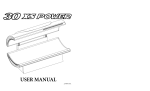
Abb. 3 Connection of the amplifier to the car radio
connector for
original cable
harness
Male and female connector for original cable
harness or car-specific
adaptor
CD The ISO female connector will either be plugged into the vehicle harness that has been disconnected from the car radio or a car-specific adaptor.
The ISO male connector will either be plugged into the car radio or into a car-specific adaptor.
The 20-pole connector will be plugged into the MATCH PP 82DSP amplifier.
The power supply terminal has to be connected directly with the battery - use only adequate
cables and fuse the +12V wire close to the battery.
®Optional: car-specific adaptor - such an adaptor may be required if the ISO connectors of
the provided PP 82DSP cable harness does not fit into your car radio.
~
20
Connection to a PC
It is possible to freely configure the PP 82DSP with
our DSP PC-tool software. The user interface is designed for easy handling of all functions and allows
to individually adjust all eight DSP channels.
Prior to connecting the amplifier to your PC, visit our
website and download the latest version of the PCtool software. Check from time to time for software
updates in order so that your amplifier is always upto-date.
You will find the software and the respective user
manual on www.audiotec-fischer.com .
We strongly recommend to carefully read the user
manual before using the software for the first time in
order to avoid any complications and failures.
Make sure that the amplifier is not connected to
your computer before the software and USB driver
is installed!
To install the software follow the next steps:
Download the PC-tool software from the website www.audiotec-fischer.com
2. Install the software on your computer. During
that process the required USB driver will be automatically installed as well.
3. After the software installation processed is
completed you can now connect the amplifier to
your PC using the provided USB cable.
4. Turn the amplifier on and then start the software. If the firmware of the amplifier is not the
latest version it will automatically be updated on
the currently selected memory position.
5. You are now ready to configure the PP 82DSP
according to your demands.
1.
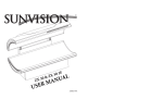
ATF DSP PC-Tool
Channel
configuration
Channel
Highpass filter
21
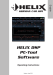
Configuration examples
Front I Rear passive system plus subwoofer
passive subwoofer front I rear channels
e.g. PP 10E
This is a classical 5-channel setup, where 4 of the 8 amplifier channels are used to drive a MATCH
subwoofer. We strongly recommend to use this configuration only in combination with our subs PP 1OE-D
or PP 8E-Q. The versions PP ?E-D and PP 7S-D may not be able to handle the full amount of amplifier
power.
Front 2-way full active system I Rear passive system plus subwoofer
front tweeter
front midbass I
rear channels
subwoofer
I voice-coil
(ideally 2 x 2 Ohms)
or
RCA line outputs for connecting a separate
subwoofer amplifier
This ?-channel configuration is recommended for highest quality in combination where the typical passive
crossover for the front midbass/tweeter is eliminated and those speakers are driven by separate amplifier
channels. The PC tool software offers a wide range of highpass/lowpass filters for precise crossover
design.
22
Output power RMS I max:
• All channels @ 4 Ohms: ............................................ 8 x 55 I 110 Watts
• All channels@ 2 Ohms: ............................................ 4 x 70 I 140 Watts
Frequency range ............................................................. 20 Hz - 22.000 Hz
Number of input channels ................................................ 4 x highlevel, 1 x Aux, 1 x SPDIF optical input
DSP resolution ................................................................. 56 Bit
DSP processing power .................................................... 172 MIPS
Total harmonic distortion (THO) ....................................... < 0,03°/o
Signal-to-noise ratio ......................................................... > 103 dB
Damping factor ................................................................ > 50
Input impedance .............................................................. 30 Ohms
Undervoltage detection .................................................... 9,6 Volts (max. 5 sec. down to 6 Volts)
Dimensions (H x W x D) .................................................. 44 x 185 x 164 mm I 1,73 x 7,28 x 6,46"
Additional features ........................................................... HD technology with dynamically controlled power
supply, ready for start-/ stop, 56 bit digital signal
processing, internal memory for 2 different sound
setups, USB input, AUX input, optical input, input
for optional remote control, stereo line outputs
with balanced output transformers (floating
ground).
The limited warranty comply with legal regulations.
Failures or damages caused by overload or improper use are not covered by the warranty.
Please return the defective product only with a
valid proof of purchase and a detailed malfunction
description.
Technical specifications are subject to change!
Errors are reserved!
For damages on the vehicle and the device, caused
by handling errors of the device, we can't assume
liability.
All MATCH amplifiers are tagged with a E-Certification number and also a CE-Certification mark.
Thereby these devices are ceritified for a use
inside vehicles inside the European Union (EU).
23
AUDIOTE C
FISCHE R
Audiotec Fischer GmbH
Gewerbegebiet Lake II · Hunegraben 26 · D-57392 Schmallenberg
Tel.: +49 2972 9788 0 · Fax: +49 2972 9788 88
E-mail: [email protected] · Internet: www.audiotec-fischer.com