1
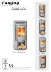
WOOD GASIFYING BOILER ATTACK DP STANDARD / PROFI INSTRUCTIONS FOR USE WWW. ATTACK.SK ATTACK DP - Wood gasifying boiler - Assembly, pre-heating and training of the attendance is perfomed by an assembly technician trained by the manufacturer, who also fills in a document on the installation of the boiler. -During wood gasifying, tar and condensates (acids) are created in the fuel bin. Therefore behind the boiler the mixing appliance regumat must be installed to keep the minimum temperature of return water of 65°C into the boiler. - Operation temperature of water in the boiler must be of 80-90°C. - The boiler must not be permanently operated with the output lower than 50%. - When a circulation pump is used, it must be controlled by a separated thermostat in order to keep the prescribed minimum temperature of return water. - Ecological operation of the boiler is during nominal output. - We recommend to install the boiler with storage reservoirs and Regumat which guarantees economy in fuel in 20 to 30% and longer service life of the boiler as well as comfortable attendance. - If the boiler cannot be attached to the accumulation, we recommend to connect it at least with one equalisation basin with the volume of about 25l for 1 kW of the boiler output. - During the mode with decreased output (summer mode and water heating) it is necessary to star t burning daily. - Fuel must be used only dried of 12 - 20% moisture content (with a higher moisture content of fuel the output of boiler decreases and its consumption increases) - The choice of the right boiler size, that is its heating output, is a very important condition for economic operation and right function of the boiler. The boiler must be chosen so that its nominal output responds to heat loss of the heated object. The guarantee does not apply for the boiler if: - it is operated with wood exceeding 20% moisture content or with fuel not prescribed by the manufacturer. - if a proper mixing appliance Regumat is not installed in the system, which provides for return water the temperature of 65°C. - a functional thermostatic valve (WATTS STS20) is not installed on the cooling circuit of boiler and connected to the source of cooling water. This appliance is not suitable for using by those persons (including children), whose physical, mental and sense- disability or the lack of skills obstucts the safe operation, if they are not under restraint, or they were not trained by the responsible person for using the appliance. It is necessary to look after the children to assure, that they will not play with the appliance. 2 Content: 2 Important 3 Content 4 Introduction, general description 5 Technical parameters 6 Dimensions of the boilers 7,8 Control board of ATTACK DP STANDARD, PROFI 9 Purpose of use, technical parameters, operational rules 10 Warning 11 Technical description of DP PROFI 12 Overheating of the boiler, the ways of regulation, displaying faults 13 Maintenance of heating system, prescribed fuel 14 Location of the boiler 15 Chimney, exhaust pipe, connecting boiler to the mains, connection to the heating system 16 Protection of boiler against corrosion 17 Installation and change of the fireproof concrete shaped peaces 18 Variants of connections 19 Variants of connections, variants of protection and boiler durability increase 20 Operation with the accumulation tanks 21 Protection of boiler against overheating 22 Possible faults and the means of their elimination 23 Scheme of dependency of resistance on the temperature of heating water by the thermal probe ( DP PROFI ) 24-27 The schemes ofelectrical connections of ATTACK DP boilers 28 Notes 3 Introduction: Dear customer, Thank you for confidence that you showed us by purchasing our product - ATTACK wood gasifying boiler. We wish you long and reliable operation. Proper attendance of the boiler is one of the conditions for reliable and right operation, so please read this instruction for use carefully. The manual is written in the way to respect the right operation of the boiler in central heating system. The conditions of right boiler operation: - to choose the right type and output of the boiler - impeccable putting into operation - sensitive attendance - regular technical maintenance - reliable service General description: ATTACK DP wood gasifying boiler is designed for economic and ecological heating of family houses, bungalows, small plants, workshops and similar objects. Specified fuel for ATTACK DP boilers is dry wood, e.g. logs of lengths, depending on the type of boiler. The wood gasifying boiler is the holder of 101 5 certificate. Description of ATTACK DP brand: ATTACK DP 25 35 45 75 95 Wood gasification boiler Standard Boiler output Version type ATTACK DP 25 35 45 75 95 Wood gasification boiler Profi Boiler output Version type 4 Technical parameters: Type of boiler DP25 DP35 DP45 DP75 DP95 Boiler output STANDARDversion ) kW 25 35 45 75 95 Output range ( PROFIversion) Heating surface kW m2 10-25 1,52 14-35 1,74 18-45 1,95 30-75 3,60 43-95 5,60 Feed hopper capacity dm3 96 112 Dimensions of feeding opening Prescribed chimney drought mm Pa Max.operating pressure of water Weight of boiler kPa kg Diameter of the flue connection mm 150 150 150 219 219 Boiler height - "A" Boiler width - "B" mm mm 1235 690 1235 690 1235 690 1320 750 1535 766 Boiler depth - "C" mm mm 1090 1190 1295 1600 1750 IP 590 21 690 21 790 21 1100 21 1100 21 W % 50 85 50 85 60 86 60 86 90 81 CO emission class Flue gas temperature in nominal output °C 230 225 220 262 287 0,019 0,021 0,027 0,045 0,059 65 65 65 65 65 The depth of the chamber - "D" Shield of the electric parts Electrical input Boiler efficiency 235x445 235x445 23 23 250 370 250 405 128 305 440 235x445 23 292x542 23 292x542 25 250 430 250 650 250 800 3 Flow of flue gas in nominal output kg/s Maximum noise level dB Dry wood of 15-17 Mj/kg-1 calorific value,water content min. 12% - max. 20% diameter 80-150mm Prescribed fuel -1 Average fuel consumption Consumption per season kgh Max. length of wood logs mm Burning time in min. output hod. Volume of water in the boiler Min.volume of equalisation basin l l Connection voltage V/Hz °C 230/50 65-90 °C 10-27 Range of temperature of heating water Range of room tempereature ( PROFIversion) Current carrying capacity of boiler regulator contacts (PROFI version) 7,75 9,75 11,75 18,7 29,2 550 650 1kW = 1m3 750 1000 1000 3 3 3 3 3 68 600 78 900 87 1200 164 1800 250 2375 V/A 230 / 2 Specified min.temperature of returnable water in operation is 65°C. Specified temperature of water during operation in the boiler is 80-90°C. ATTACK, s.r.o. producer reserves the right to change technical parameters and dimensions of boilers without previous warning. 5 Dimensions of ATTACK DP boilers ATTACK DP 25-45 DP25-35 DP45-95 ATTACK DP 75 Key: 1.Boiler body 2.Upper cover 3.Feeding door 4.Ashtray door 5.Pull rod of the heat up flap Rising pipe - "E" G6/4" G2" Return pipe - "F" G6/4" G2" ATTACK DP 95 6.Cover of cleaning opening 7.Aftercooling circuit 8.Chimney 9.Suction fan 10.Outlet valve 11.C.H. return connection 12.C.H. flow connection 13.Primary air flap 14.Secondary air flap 15.Regulation door 6 16.Output regulator 17.Control electronics - PROFI version 18.Pressure gauge Control board – ATTACK DP STANDARD Wood gasifying boiler "ATTACK DP Standard" is controlled by a boiler and flue gas thermostat. ATTACK DP 25-45 1 - Reset 2 - Fuse 3 - The main switch 4 - Flue gas thermostat 5 - Boiler thermostat 6 - Thermometer ATTACK DP 75-95 1 2 3 4 5 6 Description: 1. Reset - protection of the boiler against overheating (in case the temperature is higher than 110°C, the boiler is disconnected from the power net) 2. Fuse - protection of the boiler against short circuit 3. Main switch - switching on of the boiler,switching off if necessary 4. Flue gas thermostat - when the temperature of flue gas drops below the set up value, the fan is switched off 5. Boiler thermostat - serves for setting up maximum temperature of water in the boiler (after exceeding set up temperature the fan is switched off and the boiler works with minimum output. After decreasing set up temperature the fan is switched on again and the boiler works with maximum output. 6. Thermometer - indicates the temperature of outlet water from the boiler 7. Pull rod control - serves for opening and closing of fuel cut-off flap 7 ATTACK PROFI The ATTACK PROFI boiler version in comparison to the ATTACK STANDARD version represents higher comfort of attendance, possibility of output regulation and possibility to connect control and regulation elements. Boiler temperature is kept at the level set at by user by means of control of the flue gas ventilator´s rotations. Boiler regulator of the ATTACK PROFI boilers performs permanent measuring of temperature of water in the boiler and indicates it on display. Regulator controls rotations of the flue gas ventilator and the central heating (C.H.) pump adequately to this temperature. To the boiler regulator, the flue gas thermostat is connected, that switches boiler into the mode of the fuel shortage control, when the flue gas temperature decreases under the set temperature. There is also an option to control the gear of the mixing 4-way valve. 1 – Electronic regulator PROFI 2 – Manometer Frontal view on electronic regulator 1 – Main switch 2 – Display indicating boiler temperature and parameters 3 – Control light of additional thermostat 4 – Button of boiler thermostat 5 – Button of additional thermostat 6 – Button STOP/parameter options/Alarm cancel 7 – Button START/ parameter options 8 – Start button of programming in service menu / confirmation of settings 9 – Control light of circuiting pump Backward view on electronic regulator 1 – Connection of mixing valve (12V) 2 – Connection of additional thermostats 3 – Fuse 2A 8 Technical description and ways of regulation of the ATTACK PROFI boiler Boiler temperature is kept at the level set at by user by means of control of the flue gas ventilator´s rotations. Regulator measures temperature of water in boiler, indicates it on display and controls suction fan and circuiting pump. Regulator is equipped with additional flue gas thermostat and terminals to connect its sensor. Adequately to the situation, it is possible to use thermostat to set the flue gas temperature for indication of fuel shortage and boiler stop, or for setting of required temperature in the room. In dependence of the chosen usage, the sensor of the flue gas temperature or the sensor of the room temperature should be connected into terminals for connection of the flue gas thermostat and an adequate mode of regulation should be chosen through parameter setting. From production is thermostat used for setting of flue gas temperature. When it is set up for the first time, producer recommends to set value of the flue gas thermostat in the range of 100-120°C. Temperature is set by button of the additional thermostat in the temperature display mode. When the flue gas temperature decreases, the boiler is switched into the mode of fuel shortage. Design of appliance also enables connection of external contact thermostat into the terminals of the room temperature sensor. Connection Before you start appliance by the main switch, connect regulator, ventilator, circuiting pump and connection cords into suitable sockets in the rear part of appliance. Sensor of boiler temperature has to be placed into the boiler case. WARNING! Before you connect regulator into the mains, check, if it is properly ! grounded and if the terminal screws are fitted well. ATTENTION! Max. total output of the appliances connected regulator must not exceed ! 450W. ATTENTION! For extended function of regulator, it is possible to connect the UM-1 ! Module that enables control of additional boiler or C.H. pump. Connection of additional appliances to module’s contacts have to be separated by appropriate relay. The unused contacts of this module can stay unconnected. Operation After start of appliance, all points of display light for a while to check their correct function. After reset, the regulator switches back to the last state before stop or power shortage. Basic operation of appliance is controlled by setting of required boiler temperature set by thermostat, all other functions are performed adequately to parameters programmed in the service mode. In case that the boiler temperature setting is changed by the boiler temperature button, the change is indicated on display for several seconds (e.g. [C 75] ) and this value represents temperature that will the regulator struggling to achieve. This value can be checked in the temperature display mode. In accordance to the type of installation and service settings can be the button of additional thermostat used to set flue gas temperature or room temperature. From production is this button intended to set the flue gas temperature. When the flue gas temperature decreases under the set value, the regulator switches into the mode of fuel shortage control and after the set time period - parameter [Fb30] - is the boiler stopped. This function prevents from eventual discharging of accumulation tank after fuel burn-out in the boiler, when - after expiration of time set by parameter [Fb30] - ensures boiler operation stop to avoid of inverse heat flow from charged accumulation tank into cold boiler. Change of position of the button of additional thermostat is for few seconds indicated on display, e.g. [100°]. 9 Actual value of this setting can be also checked in the temperature display mode. If the flue gas temperature is in the operation mode after burning-up lower than the value set by the button of additional thermostat, then the suction fan and the circuiting pump are blocked, which is signalized by flickering of additional thermostat´s control light. In this case it is necessary to decrease the adjusted flue gas temperature value by the button of additional thermostat, until the control light stops to flicker. Consequently it comes to restart of the suction fan and circuiting pup operation. When the fuel is being burned-down and the flue gas temperature decreases under the value set by flue gas thermostat, the boiler is switched into the fuel shortage control mode and after expiration of the set time – parameter [Fb30] – it comes to automatic boiler stop. It is necessary to make setting of the boiler stop at flue burn-down adequately to flue gas temperature, when the boiler is started-up and then to check it from time-to-time. After pressing the START button, ventilator starts to work and the control process begins. Ventilator is stopped by the STOP button. If the regulator is not in the operation mode, temperature of water in the boiler is indicated on display. Example: [70°C] - STOP mode [70°C] - Operation mode [70°C] - Fire keeping in operation mode Manual start of ventilator During the boiler operation might the user need to turn the fan on manually (e.g. for suction of gas from boiler before and during fuel load). After pressing and holding of START button for 3 seconds, the ventilator starts. Ventilator will work for period set in service mode or until the STOP button is pressed. Temperature display mode To enter into the temperature display mode, press the OK button. Enter into this mode will be indicated by quick flickering of the additional thermostat´s control light. Use buttons < and > to browse in the information displayed to different temperatures. To exit the temperature display mode, select [END] and press the OK button or wait for 1 min. List of temperatures, which are disposable in the temperature display mode: Indication C 80 100C 180° End Parameter Required boiler temperature Temperature set by the additional thermostat’s button (flue gas / room) Actual temperature of additional thermostat (flue gas / room) Exit from menu of the temperature display 10 Required boiler temperature [C 80] - is temperature that the regulator tries to reach in the operation mode. It is set by direct turning of button of the boiler thermostat and it is indicated by short displaying. Set temperature of the flue gas / room thermostat [100C] - this parameter indicates temperature set by additional flue gas / room thermostat. In accordance to installation of heating and setting of parameter FC (1 or 0) it represents the flue gas temperature (at lower actual temperature, the regulator switches into the fuel shortage mode) or the room temperature. Actual flue gas temperature or room temperature [180°] - this parameter indicates actually measured flue gas temperature or room temperature. Setting of parameters – service menu When the OK button is held for longer than 3 seconds, it is switched to the service mode, where you can see and change programmed parameters. Service mode is indicated by flickering of the additional thermostat´s control light. It is possible to browse parameters by the + and - buttons. After selection of the required parameter you can switch into the mode for parameter change by pressing of the OK button - this mode is indicated by flickering of the parameter value. To change the value, use the + and - button. New setting can be confirmed by the OK button. Then it is possible to select next parameter (by + and -). If you wish to close service mode, select [END] by + and - and press OK or wait for 1 minute. Devices finishes service mode and starts to display boiler temperature. First column in the schedule represents display indications and in the next columns are: parameter description, minimum value, maximum permitted value of setting, step of parameter setting during adjustment, production settings to which it is possible to come by selecting of the [Prod] option.. 11 Schedule: List of service parameters Parameter Min Max Step Production settings ∏100 Max. Operation output of ventilator or max. output, when ∏r 0-10 50 100 1% 100 n 40 Minimum output of ventilator 20 40 1% 40 ∏h 10 Ventilator speed, decrease of coefficient 2 40 1 10 ∏r 1 Automatic control of fan rotations and time of fan start - -, 0 10 1 1 ∏n 5 Time of ventilator operation - -, 5 60 1s 5 ∏u 6 Time of ventilator pause 1 99 1min 6 ∏d 3 Time of ventilator operation in manual mode - -, 1 99 1min 3 P 65 Temperature of C.H . pump start-up 60 70 1°C 65 Ph 5 Hysteresis of C.H. pump 1 10 1°C 5 Pr 1 Operation mode of C.H. pump 0- Automatics 1- Pump operation depends on room temperature or on contacts of the room thermostat. 2- Pump operation depends on operation mode of regulator 0 2 1 1 Pc -- Pause of C.H. pump - -, 1 99 1min -- Pd 2 Delay to stop the C.H. pump - -, 1 99 1min 2 L 65 Minimum boiler temperature 60 65 1°C 65 H 90 Maximum boiler temperature 80 95 1°C 90 h5 Hysteresis of boiler temperature 1 10 1°C 5 A 105 Temperature of boiler overheating 95 105 1°C 105 Fc 1 Testing method of fuel shortage: 0- increase of temperature of water in the boiler 1- measuring of flue gas temperature 0 1 1 1 Fd 60 Time of measuring of fuel shortage during boiler start -up - -, 1 99, 4h 1min 60 Fb 30 Time of measuring of fuel shortage during operation - -, 1 99, 4h 1min 30 Ar 0 Operation mode of exceptional output: 0- output of start of separate boiler 1- alarm output 2- output controlling mixing valve 3- output controlling emergency after cooling system 4- output controlling next devices starting during the operation of the fan 0 4 1 0 Prod Reset of production settings outP Control of the C.H. pump outP out1 out∏ Control of fan output out∏ out2 outr Control of additional output outr out3 End Exit from service menu Display 12 Operation parameters of flue gas fan Fan output [Π100] - this value defines fan output. When the "Πr" is on "0-10", it is max. fan output that can be reached during automatic fan operation. Minimum fan output [n 40] - the lowest fan output, that can be used, when are the fan rotations controlled automatically and when the fan rotations continually increase during boiler start-up. Coefficient of the fan speed decreasing [Πh10] - this parameter influences way of the fan speed decreasing, when the boiler temperature is near to required value. For example, setting of this parameter to the value of 2 means, that when is regulator in the operation mode and boiler temperature is for 2°C lower than the required boiler temperature, fan will work at max. output [Π100]. Next increasing of boiler temperature causes continual decrease of the fan output up to its minimum [n 40]. Automatic regulation of the fan rotations [Πr 1] - is active, when this parameter is set to „010“ and causes automatic decrease of fan rotations, when temperature of water in the boiler reaches required temperature. If is the parameter set to „-“, then is the automatic decrease of fan rotations inactive and fan works at output set by the "Π" parameter. Setting of the parameter value in the range from 0 to 10 means time in minutes of the continual increase of the fan speed from 40% up to the value "Π" for correct boiler start. Operation time of ventilator [Πn 5] - time of ventilator rotation that is necessary for suction of accumulated gas before and after loading. By setting the parameter to „-“ is the function inactive. This function can be activated in the OPERATION mode. Ventilator pause [Πu 6] - time between operation periods of the fan. Operation time of the fan in the manual mode [Πd 3] - this parameter determines, how long will the fan work, when it was activated manually. By setting of this parameter to „--“ is the option of manual fan operation inactive. Parameters of the central heating pump. Temperature of the C.H. pump start [P 65] - temperature of water in boiler that causes start of the C.H. pump. Circuiting pump works independently on boiler control process, but it is started by boiler control in case of boiler overheating. Hysteresis of the C.H. pump [Ph 5] - this parameter defines at which value of decrease of the boiler temperature under the temperature of the pump start will be the pump stopped. Operation mode of the C.H. pump [Pr 1] – the C.H. pump, independently on the operation mode, is always inactive, when the boiler temperature decreases under value set by the [P 65] parameter and it is always started, when the boiler temperature exceeds 90°C, when the boiler is overheated or when the temperature sensor is damaged. In remaining cases, the C.H. pump works in the mode set by parameter [Pr] mode [Pr 0] - permanent operation mode [Pr 1] - pump work depends on additional thermostat work mode. In [Fc 0] mode central heating pump is turned on when room temperature is too low (additional thermostat connection shorted or room temperature lower than temperature set with additional thermostat knob). The pump is turned off when room temperature reaches desired value. In [Fc 1] mode central heating pump is turned on when measured exhaust gas temperature is higher than temperature set with additional thermostat knob. The pump is turned off when exhaust gas temperature drops below the set temperature. mode [Pr 2] – in this mode is the C.H. pump started only when the regulator is in the operation mode 13 Time of pause of the C.H. pump [Pc --] - when the boiler temperature exceeds the temperature set by parameter [P 65] and operation mode stops the pump (e.g. when the contacts of thermostat are open or when the fan is stopped), can the pump be regularly started for 30 seconds to pump water into the heating system. This parameter sets pause time in minutes between operation cycles of the pump. Setting of this parameter to „--“ inactivates this function. Delay of the C.H. pump stop [Pd 2] – too early C.H. pump stop might cause boiler temperature increase and consequently its overheating. This parameter enables to set delay of the C.H. pump stop. Setting of this parameter to „--“ means, that the pump will be stopped without delay. Setting of operation boiler temperature Min. boiler temperature [L 65] - min. temperature, that can be set through rotary thermostat. Max. boiler temperature [H 90] - max. temperature, which can be set through rotary thermostat. Hysteresis of the boiler temperature [h 5] - this parameter defines, to which value should temperature of water in the boiler decrease, under value set through rotary thermostat to start the suction fan. Boiler protection against overheating Temperature of boiler overheating [A105] – boundary value - after exceeding of this value is the suction fan indefinitely stopped and the circuiting pump is started to prevent from boiler overheating. The overheating mode is indicated by the control light of boiler overheating and error messaging [E 2] on display. Error can be turned off by pressing STOP button, but only when the boiler temperature decreases under the set value of the boiler overheating temperature. The suction fan is stopped also, when the boiler thermostat sensor is damaged and this error is displayed as message [E 1]. Emergency thermostat – regulator has also additional protection against overheating, which is independent from processor. In case of temperature increase to 95°C , the control process is launched by ventilator stop and pump start. Ventilator and pump are included into the control process again, when the temperature reaches 89°C. Emergency thermostat enables more precise boiler regulation and eliminates possibility of overheating. Fuel shortage testing If central heating installation is equipped with exhaust gas temperature sensor ([Fc 1]), then fuel shortage testing starts when exhaust gas temperature falls below temperature set with additional thermostat knob. If there is no exhaust gas temperature sensor ([Fc 0]), then fuel shortage testing starts when boiler water temperature falls below value of [L 65]. If temperature tested during fuel shortage testing stays below threshold for specified time, the controller will stop regulation process and will show [FUEL] message on the display. This alarm can be erased with STOP button. Fuel shortage control during the boiler start [Fd 60] - the time set by this parameter is used for fuel shortage control during the boiler start. Boiler is considered as started, when the regulator is switched from the STOP mode to WORK mode and finishes, when the boiler temperature exceeds minimum temperature set by the parameter [L 65]. Setting of parameter [Fd 60] to „--“ inactivates fuel shortage control during the boiler start. Time of fuel shortage control in the operation mode [Fb30] – the time set by this parameter is used, when the fuel shortage control starts after the boiler was started. Setting of this parameter to „--“ inactivates fuel shortage control in the operation mode. 14 Additional output. Mode of additional output [Ar 0] - regulator is equipped with the multi-purpose output that can work under one of the following outputs: Mode [Ar 0] – can control oil or gas boiler, if it is connected into the heating system. When the regulator is started by the main switch, the additional boiler is stopped and it is started again, when there is already no fuel in the solid fuel boiler. This function is useful in the heating systems, where the solid fuel boiler is used to decrease the heating costs. When the fuel shortage alarm is removed by the STOP button, the additional boiler is stopped again and the regulator works again. Mode [Ar 1] - the outlet can control next system that signalizes alarm. Error of the boiler temperature sensor, overheating or in case of the fuel shortage is the next alarm started. Mode [Ar 2] - the outlet can control emergency cooling circuit of the boiler (e.g. pump). In this mode, the next outlet is started in case of the boiler overheating or of the boiler temperature sensor error alarm. Mode [Ar 3] - the outlet can control devices that are cooperating with compression fan. ATTENTION - Devices should be connected to the next outlet by the UM-1 module (not included to delivery). Connection of the UM-1 module is described on the Pic.1. Regulator outputs testing To simplify the regulator control, it is possible to control the output circuits that regulate ventilator and pump and the circuits that control next boiler. By selection of [outP] on display and by pressing the OK button you can start the circuiting pump for a short time. By selection of [outΠ] and pressing OK you can start the fan. By selection of [outr] and pressing OK you can start the additional boiler, system signalizing alarm or the servo-motor of the mixing valve. (if the next module is connected). Production setting Regulator offers possibility or reset the standard settings defined by producer by the [Prod] option in the service mode and by pressing the OK button. After activation of this function, device sets every parameter given in the schedule to the production setting. Exit from menu By selection [End] on display and by pressing of the OK button you can exit the service menu. Device closes the service menu also, if no button is pressed within 1 minute. Additional functions Regulator is equipped with additional thermostat and terminal for its connection. This thermostat is used from production to connect the flue gas thermostat. The [Fc 1] parameter – when the flue gas temperature decreases under the set value, regulator switches boiler into the mode of the fuel shortage control. This thermostat can be used also as the room thermostat. Parameter [Fc 0]. In this case should be the sensor of the room temperature connected to the terminal of additional thermostat. The RK-2001AT2 compares measured room temperature with temperature set by additional rotary thermostat. When is the room temperature lower than the temperature set by thermostat, 15 control light of the room thermostat will shine, because the boiler should keep the temperature set by the boiler thermostat. When the room temperature exceeds the set temperature, control light of the room thermostat expires and the boiler switches into the mode of fire keeping at minimum boiler temperature. Device is designed to enable connection of alternative external thermostat instead of the room temperature sensor. Short circuit of contacts in case of low temperature starts the heating process described above. When contacts are open, the regulator will keep the minimum boiler temperature. Attention! If the external thermostat is connected at the place for connection of the room temperature sensor, temperature set by the room thermostat button has no influence on regulation process and the room temperature will depend only on the temperature set by the external temperature. Parameter [Fc 1] - means that exhaust gas temperature sensor is connected to the additional sensor connection. In this case the value set with additional thermostat knob specifies desired exhaust gas temperature. If the controller is in WORK mode and boiler water temperature has reached value set with [P 65] parameter, then exhaust gas temperature drop below temperature set with additional thermostat knob will stop the fan. If central heating pump is in [Pr 1] mode, the pump will also stop in this case. Additionally, if exhaust gas temperature is below desired temperature, this will also be signalled with quick blinking of thermostat indicator. Error messages Boiler regulator permanently tests correct function of the internal systems and of the boiler temperature sensor. When the error is detected, regulator stops flue gas fan, C.H. pump and at the same, the appropriate error message is displayed. In case of accident it is necessary to stop the boiler by the main switch. Ensure permanent operation of the circuiting pump by direct connection to the electricity mains. Ensure proper fuel combustion in the boiler and contact contracted Service Company. When the error [E 1] is displayed, it means fault (short circuit) in the circuit of the boiler temperature sensor or temperature under -9°C. The [E 2] is displayed, if the boiler is being overheated. The [E 3] means error and overheating at the same time. When the [E 1] error is displays without possibility to remove it by pressing the STOP button, despite the boiler temperature is under 90°C, it might mean permanent damage of the boiler temperature sensor (e.g. in case, that the boiler was overheated to the temperature over 150°C). Error [E 8] indicates flue gas sensor failure. In this case, the regulator will not control fuel shortage. Disassembly of appliance In case of need, disassembly regulator from system: - turn the main switch off - disconnect boiler from electricity mains - unmount cover of the boiler´s control panel - disconnect all connectors with cables from regulator - unmount regulator from opening on the control panel of the boiler ! WARNING: TO PREVENT FROM INJURY BY ELECTRICITY, DO NOT UNMOUNT THE COVER BEFORE DISCONNECTION FROM ELECTRICITY MAINS. 16 Connection of module UM-1 Regulator Regulator Gas boiler, electric boiler Alarm, other devices 17 Purpose of use Ecological hot-water boiler Attack DP is designed for heating of family houses and similar objects. The boiler is designed for burning wood only. Any dry wood can be used for burning, mainly logs. Also wood of bigger diameter, blocks, can be used, which reduces nominal output but prolongs burning time. The boiler cannot be used for burning filedust and small wooden debris. This can be burnt only in small amount together with logs (max. 10%). Due to its large feed hopper you can avoid the most demandable operation of preparation and cutting the wood into smaller pieces. Location of the boilers in living spaces (including halls) is inadmissible! Technical parameters The boiler is designed for combustion of wood on the principle of wood gasifying using a flue gas fan sucking flue gas from the boiler. The body of the boiler is a weldment of metal steel plates of 6 mm thickness. It includes a feed hopper with a heatproof shaped piece that has an oblong opening for transition of flue gas and gas. Under it in the after-combustion space there is an ash pan. In the rear part of the boiler there is vertical flue channel with a fuel cut-off flap in the upper part. There is also a suction branch for connection to the flue. In the front wall in the upper part there is a feeding door and in the bottom part there is an ash door.In the front part of the upper cover there is a pull rod of fuel cut-off flap. The body of the boiler is from the outside insulated by mineral fleece put under the covers of outside jacket.In the upper part of the boiler there is a control board for electromechanical regulation. . In the rear part of the boiler there is a channel for inlet of primary and secondary air with a regulation flap where the air is heated to a high temperature. Description of the STANDARD version - Thermometer indicates outlet temperature of the boiler - If it is necessary, the boiler can be switched off by main switch - Electric circuit is protected by a fuse - Fan can be switched off by a flue thermostat after burning down fuel. ATTENTION! For heating up, set this thermostat to 0°C. After fuel starts burning, set the flue thermostat to "Operation".If the temperature of flue gas drops below set up temperature the flue thermostat is switched off. If you want the fan start again, you have to set up a lower temperature.The optimum condition for operation must be tried. - Regulation thermostat controls the operation of the fan by the outlet temperature of water from the boiler. Safety non-returnable thermostat serves as a protection against overheating in case of breakdown of the regulation thermostat or as an alarm of device for overcoming safety temperature. After overcoming the temperature of 110°C it is necessary to press it. (in the PROFI version turn the boiler thermostat to the left point of "RESET") Operation rules Preparing the boiler for operation Before putting the boiler into operation make sure whether the system is filled with water and deareated. The boiler can be operated only in accordance with these instructions in order to work properly. It can be operated only by an adult. When installing the boiler, lay something under the rear part to elevate it in 10 mm for better flushing and deareating. 18 Warning! After the first heating up, there can be condensation and condensate may leak. This is not a defect Condensation disappears after longer heating. When burning smaller wooden waste it is necessary to check the temperature of flue gas which must not overcome 320°C. Otherwise the fan can be damaged. Creation of tar and condensate in the feed hopper is a phenomenon accompanying wood gasifying. If the boiler was out of order for a longer time (switched off,broke down), it is necessary to use extreme caution when putting into operation again. In not working boiler, the pump can be blocked, water can leak or the boiler could get frost in winter. Heating up and operation Before burning the fuel open the fuel cut-off flap pull the pull rod of the flap and set the flue thermostat to 0°C. Through the upper door put dry wood chips on the heatproof shaped piece perpendicularly to the channel to leave 2-4 cm gap between the fuel and channel for transition of flue gas. Put paper or wood wool on the chips, then chips again and a bigger amount of dry wood. After burning the fuel switch on the fan and close the fuel cut-off flap. On the thermoregulation valve set the demanded temperature of water (80- 90°C). After proper start fill in the whole fuel bin and set up the fuel thermostat into operation position. CAUTION: During the operation the pull rod of fuel cut-off flap must be shifted in otherwise the fan can be damaged. To gasify wood, there must be a reduction zone in the boiler (a layer of charcoal on the ceramic shaped piece in the feed hopper). The layer can be created by combustion of dry wood of proper size. When wet wood is burned, the boiler is not working as a gasifying boiler and the consumption of wood rises, output is lower than demanded and the service life of boiler as well as that of flue is shortened. If the draft is as specified, the boiler works up to 70% of output even without a fan. Electromechanical output regulation Output is regulated by flap on the rear part of boiler, which is controlled by the output regulator. This regulator opens or closes the flap automatically, according to adjusted outlet water temperature (80 - 90°C). It is necessary to set the regulator carefully, because it regulates output and also subserves important function of boiler protection against overheating. Fasten the chain by bigger hook to mounted and complete regulator. Set the temperature on regulator to 80°C (for setting of temperature, use the red scale). Open the inlet flap to maximum by fastening it to the second end of the chain. Heat the boiler up. When the water temperature reaches 80°C, after few minutes, adjust the chain length to let the door open for 3-5mm. Ensure the adjustment by adjusting screw on the flap. If the boiler temperature differs from adjusted one during the operation, change the chain length adequately. Consider also another influences, that may have consequences on boiler temperature (fuel amount, ash, position of secondary air flap, persistence of boiler and whole system, etc.). Check protection against overheating by testing the regulator´s function already at the temperature of 90°C. The regulation flap has to be almost closed at this temperature. It is necessary to test adjustment of regulator. Position of regulation flap can be seen from the rear part of the boiler. Fan is controlled by boiler thermostat on the boiler panel, according to adjusted outlet water temperature. The temperature set on the boiler thermostat should be lower for 5°C than temperature on the thermoregulator. The flue gas thermostat is also placed on the panel. It serves to shut down the fan after burning-out of fuel. During the heating up, set it to the „0°C position“. After sufficient flaming up, set it to the operation position to let the fan run and to turn it only after burning-out of fuel. It is necessary to find the optimum position of the flue gas thermostat adequately to the sort of fuel, chimney draught and other conditions. Watch the outlet water temperature via thermometer. Also the nonreturn safety thermostat is placed on the panel (Standard version). Refueling For refueling first open the fuel cut-off flap by the pull rod, do not stop the ventilator. Wait for some 10 seconds, then slowly open the feeding door so as accumulated flue gas can be draught to the flue. During heating keep the feed hopper always full. To prevent smoke, stoke other fuel only after the original charge is burnt out at least to 1/3 of the content. Then cover live coal with a broad log and fill in as usually. The fuel must not be pressed over the jet as this could cause extingiushing the fire. CAUTION! During operation the pull rod of fuel cut-off flap must be shifted in, otherwise the fan can be damaged. 19 Technical description of ATTACK DP PROFI: During the operation, the display is showing the current temperature of outlet heating water. Speed of the fan are controlled in this way: - if during burning up proces the boiler temperature is lower than 45 °C, the fan works with the output set up by the turning of burning up button situated in rear side of regulator in the range of 40 - 100 %. (you can see it on the display, from r4 = 40% to r9 = 90 %, rF=100%), for boiler temperature higher than 45°C the fan works up to 100%. - if the temperature of heating water during the operation is more than 10°C lower than the one set up by the turning button, the fan works in 100 % output. - if the temperature of heating water is lower than 10°C from the temperature set up by the turning button of the boiler thermostat, the regulator decreases the output of ventilator according to the difference between these temperatures but only to the output not lower than 40%. - if the boiler temperature is higher or equal to the temperature set up by the turning button of the boiler thermostat, the fan switches off. - the ventilator switches on again after decreasing the boiler temperature in o 5°C comparing to the set up temperature. The regulation of boiler ensures that the pump for central heating switches off when the temperature of oulet water in the boiler decreases under 60°C. The pump switches on again by the temperature higher than 65°C. To prevent explosion of accumulated gas during ignition, the boiler regulator ensures purging of gas in the boiler in 5 seconds and then each minute until 9 minutes according to the position of the turning post-purge time button in the rear part of the regulator. During the set up there is always information on the display which lasts 2 seconds (P1,...., P9, P-). In case you do not wish purging of gas in the boiler, it is necessary to set up (P--). To make the process of burning up the boiler stable, there is a burning up system installed in the regulator. After plugging in or stopping the alarm the regulator is set up to the process of burning up and this mode is signalled by a shining dot on the display. The process of burning up is finished when the dot stops shining and the boiler temperature reaches the value set up by the thermostat. In case the temperature in the boiler does not exceed 65 °C in 2 hours of burning up time, the regulator stops the waste-gas ventilator and switches on the control light - missing fuel. In the time of burning out the boiler when the temperature falls under 65 °C and this condition lasts for more than 30 minutes, the regulator stops the flue-gas fan and the control light of missing fuel shines on. Missing fuel When the temperature of heating water in the boiler falls under 65 °C and this condition lasts for more than 30 minutes, the regulator stops the flue-gas fan and the control light of missing fuel shines on. If in the burning up process the boiler temperature does not raise to more than 65°C, missing fuel will be shining on the display after 2 hours. To start the regulation again, it is necessary to: - refuel the boiler; - burn the boiler up - turn the turning button of the boiler thermostat into the maximum left position and thus stop the alarm - wait until the control light of missing fuel flickers, - by turning button of the boiler thermostat set up the required temperature of the boiler and the regulator starts the process of burning up 20 The boiler overheating If the temperature of the boiler raises to more than 95 °C, the regulator stops the flue-gas fan and the control light of boiler overheating shines on. For new start it is necessary to: - wait until the boiler temperature falls - remove the cause of boiler overheating (e.g. refill missing water into the central heating circuit) Warning! Water can be refilled only after the boiler temperature falls under 40°C. - turn the button of the boiler thermostat into the maximum left position ad thus stop the alarm - wait until the control light of boiler overheating starts flickering; - to start the regulator again, set up the required temperature of the boiler by the turning button of the thermostat; If the temperature falls under 60 °C, the regulator comes into the burning up mode. The options of boiler regulation ATTACK DP PROFI The boiler enables regulation of room temperature as well as connecting the sensor of room temperature. If the room temperature is lower than the set up one, the control light near the button of thermostat shines on, which means that the boiler must keep the set up temperature. After reaching the required temperature the control light switchces off, the circuit pump of central heating switches off and the boiler starts burning at the temperature of 65 °C. For the purposses of timing regulation by room temperature it is possible to connect any optional programmable thermostat with the terminals for the sensor of room temperature. In this case the turning button of the room thermostat is not working. If you do not wish to use the room thermostat nor the room sensor, the inlet terminals must be short-circuited. In this case only the boiler thermostat is working. The mixing valve with the 12V electric drive can be also connected to the boiler regulator . (This system is not delivered with the boiler). Displaying faults: The boiler regulator constantly verifies the functions of internal systems and of the sensor of boiler temperature. After finding out the defect, the regulator switches off the flue-gas fan, the central heating pump and at the same time the defect shows on the display. In the case of failure it is necessary to switch the boiler off by the main switch,to assure the continuous operation of the central heating pump by plugging into the mains, the fuel must be burnt thoroughly and the contract service company contacted. If E1 fault appears on the display, it means the damage of the sensor of boiler temperature. 21 Permanent-heat operation Permanent-heat operation of the boiler means that the fire can be kept during the night without heating up daily, but only in winter. This way of operation shortens the service life of the boiler. For permanent-heat operation prepare the boiler this way: - Put a few bigger logs (4-6)on the glowing layer - Get the mixing valve ready. After closing the valve the temperature of water rises to 80- 90°C. - Regulation flap controlled by the thermoregulator is closed automatically and the fan is switched off. In the boiler prepared like this burning is kept for more than 12 hours. During permanent-heat operation the temperature of water in the boiler is 80 - 90°C. Cleaning the boiler The boiler must be cleaned regularly and properly every 3-5 days because ash settled down in the feed hopper together with condensates and tar decreases output and service time of the boiler and isolates heatexchanging surface. When there is too much ash, there is not enough space for burning out of fuel and a holder of ceramic jet as well as the whole boiler can be damaged. When cleaning the boiler, firstly turn the ventilator on, open the feeding door and wipe the ash through a slot into bottom space. Leave long unburnt logs in the feed hopper. Open the upper cleaning cover and clean inside with a brush. After opening the bottom cleaning hole take ash and soot out. After opening the bottom door clean the bottom space. Cleaning interval depends on the quality of wood (moisture content), heating intensity, draft of the flue and other circumstances. We recommend to clean the boiler once a week. Do not pull the fireclay shaped piece out when cleaning. Once a year minimally clean the moving wheel of the fan and check through the cleaning hole fouling of regulation of primary and secondary air flowing into feed chamber and clean with a screwdriver if necessary. It influences the output and quality of burning. WARNING - Regular and proper cleaning is important for permanent output and service life of the boiler. In case of insufficient cleaning the boiler can be damaged and guarantee expires. Maintenance of heating system and boiler At least once in fortnight check or fill up water in the heating system. If the boiler is out of operation during winter, water can be frost in the system. Therefore it is better to discharge water of the system or fill in with antifreeze agent.Otherwise discharge water only in critical situations and for the shortest time possible. After heating season is finished, clean the boiler thoroughly, replace damaged parts. Twice a year clean the moving wheel of the ventilator and its air chamber. Changing the packing cord of the door Dismantle the old packing cord with a screwdriver and clean the rabbet where it was placed. Take the new packing cord and put its begining on the horizontal parts of the rabbet. With your hand or light knock of the hammer press it into the rabbet on the circumference of the door. Adjustment of hinges After some time the packing cord in the door gets deformed. To repack the door, it is necessary to change the position of the door. The position is changed by tightening the hinges of the door. Feeding door and bottom door are joined to the body with two hinges which are attached to the door with a long pin. If we want to change the adjustmnent of hinges, it is necessary to remove the pin and screw the hinge by turning it. Fit the door on and insert the pin into the hinge. Exchange of the nozzle body The body of nozzle is placed in the boiler body in a nozzle holder. In the lower part is the nozzle body sealed by boiler lute and in the upper part by a packing cord. When exchanging the nozzle, remove the packing cord from the rabbet by a screwdriver. Remove the nozzle body and clean the holder thoroughly from the tar and old lute. On the cleaned surface put the nozzle body insulation. Take the nozzle and put it on the holder so that the shorter wall was in the rear part of the boiler pushed to the stop. The lateral clearance must be the same. Take the new set of packing cords of the nozzles and with a light knock press it into the gap so as to be at the same level with the nozzle. Setting of the boiler combustion Setting of the boiler combustion is executing through the regulations flaps of the primary and secondary air. Boilers are from the production set for the most optimal burning conditions in term of the emissions and the tempertature of exhaust gas.Setting can be executed only by producer or by trained serviceman. : The most optimal setting of the regulation flaps: flap of the primary air: DP25totally closed /backstop/ DP35 totally closed /bacstop/ DP45 totally closed /backstop/ DP75 backstop +5 mm DP95 MIN closed position + shift of 1/3 of the range flap of the secondary air:: DP25 backstop + 2 mm DP35 backstop+2 mm DP45 backstop +4 mm DP75 backstop +4 mm DP95 closed position MAX Prescribed fuel Specified fuel is dried cut wood and logs of 80-150mm diameter, with min. 12% and max. 20% moisture content and calorific value of 15 - 17MJkg-1. It is also possible to burn big pieces of wooden waste with thick logs. 22 Note Logs of bigger dimensions is necessary to cut into halves or quarters (because of the requirement of operation to nominal output). You can burn hard as well as soft wood. Wood must be dried! Boiler output depends on the moisture content of wood. Output and function of the boiler is guaranteed for maximum moisture content of 20%. Calorific values of the most used kinds of wood Wood Spruce Pine Birch Oak Beech kcal 3900 3800 3750 3600 3450 Heat energy for 1kg MJ 16,25 15,80 15,50 15,10 14,40 kWh 4,5 4,4 4,3 4,2 4,0 Location of the boiler: For the installation it is necessary to keep safe distance of its surface from flammable materials by the degree of flammability and combustibility: - materials B, C1 and C2 200mm - materials C3 400mm - materials with the degree not tested by STN 73 0853 400mm Examples of building material devided by the degree of combustibility: - A degree- noncombustible (bricks, blocks,ceramic linings, morter, plaster) - B degree- very difficult to ignite (heraklith, lignos, boards from bazalt felt) - C1 degree - difficult to ignite(broadleaves- beech, oak; plywood, werzalit, hard paper) - C2 degree - normal combustibility (coniferous species -wood, pine, spruce pulpboard, solodur) - C3 degree - easily ignited (wood pulpboards, polyurethane, PVC, foam rubber, styrofoam) Non-combustible board or protecting fire- screen ( on the protected subject) must exceed the boiler dimensions at least 300mm. All the other subjects from combustible materials, which are situated near the boiler, have to be protected by non-combustible board or fire-screen, if it is impossible to keep the safe distance. If the boiler is located on the floor from combustible materials, the flor must be covered with the non-combustible, thermal insulating pad exceeding the boiler planview at least 100mm on the side with feeding door and ash door . All the solid materials of "A" degree of combustibility can be used for thermal insulation. When locating the boiler in the boiler room, there must be a free space of min. 1 meter in front of the boiler and of 0,5 m from the side walls and the rear. Above the boiler there must be a free space of min. 1 meter. This space is necessary for basic operation, maintenance and service of the boiler. Location of the boiler in the dwelling spaces (including halls) is not allowed! The cross of opening for air inlet to the boiler room is recommended to be at least 200cm2 depending on the boiler output. ATTENTION! The objects from easily combustible materials cannot be placed on the boiler or the nereby in the distance shorter than the safe distance. If there is a danger of fire or blow up during the work ( p.e. the work with texture materials, sizing materials, etc.) the boiler must stand off operation. 23 Chimney Attachment of the appliance to the flue must be always done with approval of authorized chimneysweeping company. There must always be sufficient draft in the flue and flue gas must be draught to the atmosphere in all possible operation conditions. For the right operation of the boiler the independent flue must be dimensioned in the right way, because combustion, output and service life of boiler depends on the draught. The draught is influenced by the section of flue, height and roughness of the internal wall. Into the flue where the boiler is attached, no other appliance can be attached. The flue diameter must not be smaller than the outlet on the boiler. Flue draught must have the specified values. But it must not be too high so as not to decrease the efficiency of boiler and interrupt burning. If the draught is too strong, install a throttle valve between the flue and boiler. Informative values of flue section: For DP25, DP35, DP45 DP75, DP95 20x20 cm min. height 7 m Ø25 cm min. height 9 m Ø20 cm min. height 8 m Ø30 cm min. height 7 m 15x15 cm min. height 11 m 25x25 cm min. height 8 m Ø16 cm min. height 12 m Flue draught is specified in technical parameters. Exhaust pipe Exhaust pipe must have the outlet into the chimney. If the boiler can not be attached to the chimney directly, the exhaust pipe must be as short as possible and not longer than 1m without heating surface and it must rise to the flue. Exhaust pipes must be tight and resistant against flue gas leakage and cleanable from inside. Exhaust pipes must not come through home and utility spaces and the internal section of the exhaust pipe must not be narrowing to the flue. Using bents is not suitable. Connecting the boiler to the mains net The boiler is connected to the mains of 230 V, 50 Hz by a supply cord and plug. The voltage is of M type and when replaced, the same type must be used by a service oragnization.The appliance must be located in such a way that the plug was within the reach of the attendance. (according to STN EN 60 335-1 + A11:1997). Installation of the boiler to the heating system The ATTACK DP boiler only by a company certified for the installation and assembly of heating equipment. Before the installation there must be a project responding to valid regulations. Before installing the boiler to the old heating system, the installing company must sluice out the whole system to clean it. The heating system must be filled by the water of quality according to STN 07 7401:1991, especially the hardness of water cannot be more than 1 mmol/l and the ia Ca2+ cannot be more that 0,3 mmol/l. If these conditions are not kept, the warranty cannot be accepted. Boiler transport Producer enables better manipulation with the boiler by the eyes welded on the exchanger. They ensure better clamping of chain or rope that can be used to place the boiler as it is required. Before beginning of transport, put down the upper covers. Place the boiler by using of eyes and rope to the required location and put the upper covers back. To ensure safe manipulation with the boiler, it is necessary to leave appropriate space. For manipulation, use only devices that are technically in conformity with technical norms and control them in adequate way, not to threaten safety of the people. Special machineries have to be attended by trained staff. Producer takes no responsibility for damages caused by incorrect manipulation and by breaking instructions given in this manual. Producer also takes no responsibility for bodily injuries caused by breaking safety instructions. 24 Attachment of regulation and control elements The boiler is delivered to a consumer equipped with basic regulation and control elements. Attachment of these elements is indicated on the chart of connection. We recommend to extend the regulation of boiler with other regulation elements which enable more comfortable and economic operation. Each pump in the system must be controlled by an individual thermostat so as the boiler was not undercooled on the inlet of returnable water under 65°C. Attachment of these elements can be suggested by a designer due to specific conditions of the heating system. Electric installation together with the proper equipment of the boiler must by done by a specialist in compliance with valid standards. The basic version of boiler (Standard) does not have a thermostat for pump built in. Protection of boiler against corrosion Suitable solution to this problem is mixing appliance Regumat ATTACK-OVENTROP, which enables separated boiler and heating circuit. This way you can prevent undercooling of boiler under 65°C and also decrease condensation of steam, acids and tars in the feed hopper. The mixing system Regumat keeps the constant temperature of return water flowing into the boiler on 65°C by setting the thermostatic head to 5 - 6 degree. Water in the boiler must be permanently of 80-90°C. Section cross boiler - combustion chamber 25 Installation and exchange of the heatproof shaped piece ( version 1) The back part of the ash pan pos. 1 insert into the lower chamber and push to stop to the back plate. Insert the front part of the ash pan pos. 2 and push to stop to the back part of the ash pan. Put the super-structure of the ash pan pos. 3 on the ash pan and push it to stop to the rear. The ash pan should be situated in the centre lime of the boiler at the front sight.When exchanging damaged jet pos. 4 or cube pos. 5 , follow the next instructions: Take out the jet and the cube / the cube in DP35 and DP 45 only/ after the elimination of the gaskets. Then insert the new jet eventually the cube and seal up with gasket backwardss. If it is necessary, change also the gaskets. The jet is inserted regarding the sign on the lower part of the jet into the rear part of the boiler. VERSION 1 VERSION 2 Installation and exchange of the fireproof concrete shaped peaces (version 2) Put the rear part pos.1 into the lower chamber, the intagliated part backwards. It is necessary to put it in horizontal possition and then turn it. Place it to the centre of the chamber and push it to stop to the rear steel plate. Insert the left front part pos.2 to lower chamber, it is necessary to insert this part horizontally and then turn it. Use the same method for the right front part of the ash pan pos. 3. Push both the parts together to stop and then pull them to the rear part of the ash pan. VERSION DP75 VERSION DP95 26 The variants of connections The variant of connection with the regulating system REGUMAT ATTACK-OVENTROP The pump 1 2 Regumat ATTACK-OVENTROP Expansion vessel 3 Return flap Storage tank for DHW Heating system 4 Return Flap 27 ATTACK DP boiler The variant of connection with the accumulation tank 1 2 Regumat ATTACK-OVENTROP THE ACCUMULATION TANK the return flap The pump Heating system STORAGE TANK FOR DHW 3 4 ATTACK DP boiler Expansion vessel The boiler has to be operated continuously in nominal output. In case of heat outlet when the boiler operates on a lower output that the nominal, it is necessary to attach the boiler to the accumulation tank of the volume of min. 460 litres (STN EN 303-5, paragraph 4.2.5 ). The variants of protection and boiler durability increase 1. Regumat is used to increase the reurn heating water temperature returning into the boiler to more than 65°C. The return water temperature below 60°C causes increasing formation of condensate and the tar, and then decreasing of boiler durability. 1 2 Technical parameters: Clarity DN25 Max.pressure 10 bar Max.temperature 120°C Value kvs 3,9 Clarity DN32 Max.pressure 10 bar Max.temperature 110°C Value kvs 0 3 4 Regumat consists of three-way mixing valve, circulation pump, closting cock, thermometers and insulation. The advantage of this solution consists in its compactness, simplicity of attendance and in guarranteed protection of the boiler thermal exchanger. Regumat for the boiler Ordering code ATTACK DP25, DP35 (DN25) DPP25003 ATTACK DP45, DP75, DP95 (DN32) DPP25006 28 2. Connection with accumulation tank Connection system consists in heating up of water in accumulation tanks and the warmth is gradually taking away from the tanks according to the request from the heating system. By the operation with several heating ups at full performance, accumulation tanks will be heated for the temperature of 90-100°C. Heating with accumulation tanks in connection with the ATTACK DP boilers bring more advantages. Among the main advantages belong enlargement of the boiler life and in the end result also lower consumption of fuel. Recommended volumes of accumulation tanks according to boiler output: DP25 - 1500 - 2000 l DP35 - 2000 - 2500 l DP45 - 2500 - 3000 l DP75 - 4000 - 4500 l DP95 – 5500 – 6000 l The operation with the accumulation tanks After making- fire phase, the boiler heats the water in the accumulation tank to 90 - 100°C by full output in 2 - 4 feedings. After next feeding the heat is taken from the accumulation tank only, through the three-way valve. The offtake period depends on the tank volume and external temperature. In heating season it can be 1 - 3 days (if the prescribed min. volume is respected). If it is not possible to use the prescribed volume of the tank, it is recommended to use at least one tank of the volume of 500l for start of operation and for afterburning of the boiler. Minimum accumulation tank volume is described in the tabel of technical parameters. Standardly supplied accumulation tanks Type of tank AK500 AK800 AK1000 AS500 AS800 AS1000 Volume(l) Diameter(mm) Height(mm) 500 800 1000 500 800 1000 650 790 790 650 790 790 1650 1730 2050 1650 1730 2050 thermal changing surface(m2) 2,0 2,4 2,8 The tank insulation The accumulation tanks ATTACK AK500, AK800, AK1000, AS500, AS800 and AS1000 are usually supplied with detachable insulation from soft polyurethane with white leatherette cover. 29 The advantages The boiler installation together with the accumulation tank offers several advantages: - lower fuel consumption (up to 30%). The boiler works in full output to fuel burn-up when the optimal operation is observed - High chimney and boiler durability and minimum formation of acids and condensate - Possibility of combination with another heating sources ( solar panels...) - conjunction of boiler and floorheating - confortable and ecological heating Protection of the boiler against overheating CAUTION: Cooling circuit against overheating must not be used by STN EN 303-5 for other use than protection against overheating. Valve on the cold water inlet to cooling circuit must be opened constantly and the heating circuit has to be connected with the functional cooling water feeder (p.e. the cold water from water supply) with the temperature of 1015°C and the pressure of 2-6bar. STS 20 valve which has a sensor placed in the rear part of the boiler protects the boiler against overheating. If the temperature of water in the boiler overcomes 95°C, the valve lets water into a cooling circuit which overtakes excessing heat. In case of boiler overheating and STS20 valve opening the constant off-take of heated water from heating circuit to waste piping has to be assured. Unsecured cooling circulation in the cooling circuit when the STS20 valve is opened, can cause the boiler damage! In that case the guarrantee cannot be applied. Instructions for liquidation of the product after its lifetime After the period of use the product has to be liquidated in a compliance with the local standards and norms. Liquidation of wrapping The wrapping has to be liquidated according to local standards and norms. 30 31 Scheme of dependency of resistance on the temperature of heating water by the thermal probe ( DP PROFI ) Temprerature °C -55 -50 -40 -30 -20 -10 0 10 20 25 30 40 50 60 70 80 90 100 110 120 125 130 140 150 MIN 951 1000 1105 1218 1338 1467 1603 1748 1901 1980 2057 2217 2383 2557 2737 2924 3118 3318 3523 3722 3815 3901 4049 4153 Resistance kOhm 980 1030 1135 1247 1367 1495 1630 1772 1922 2000 2080 2245 2417 2597 2785 2980 3182 3392 3607 3817 3915 4008 4166 4280 MAX 1009 1059 1165 1277 1396 1523 1656 1797 1944 2020 2102 2272 2451 2637 2832 3035 3246 3466 3691 3912 4016 4114 4283 4407 32 The schemes of electrical connection of ATTACK DP STANDARD, PROFI boilers ATTACK DP STANDARd 25 - 75 t(°C) 1 PE BT-1 ST-2 4 1 1 PE HL PT-C SN t(°C) 1 HN PT-1 4 PE 1 BT 1 2 ST-C 5 SL t(°C) KT BT-C ST HV 4 1 t(°C) 4 1 1 TČ 95 TČ 95 1 2 3 4 5 6 7 8 9 10 11 12 4 3 2 KO KEY FOR DP BOILERS 5 230V/50Hz HV - Main switch ST - Flue gas thermostat KT - Boiler thermostat BT - Safety thermostat KO - Condensator TC - Pump thermostat 2 1 - Black wire 2 - Blue wire 3 - Brown wire 4 - Yellow-green wire 5 - Red wire - Pump - Fan - Earthing 1 4 2 2 TC 95°C F 2A/250V 1 4 33 ATTACK DP STANDARD 95 34 ATTACK DP PROFI 25 - 75 230V/50Hz N 4 2 1 4 4 2 2 L 2 L 1 N 1 2 3 4 5 6 7 8 9 4 N L 10 11 12 4 2 3 KO THE KEY FOR DP BOILERS 5 HV - Main switch KO - Condensator 4 1 BT - Safety thermostat 2 230V/50Hz ST - Flue gas thermostat KT - Boiler thermostat TC - Pump thermostat 1 - Black wire 2 - Blue wire 3 - Brown wire 4 - Green-yellow wire 5 - Red wire - Pump - The fan - Earthing 35 ATTACK DP PROFI 95 36 ! This page serves for confirming service examinations and is kept by a customer ! ! RECORD ON PUTTING THE BOILER TO OPERATION Data on the customer (llegible) Production number.............................. Date of putting to operation................ Service organization: ............................ .Stamp, signature ........................................................ Name and surname: ......................................... Street: ............................. Post code, town:. ........................................ Tel. No. .......................... Obligatory service examination after the 1st year of operation Date : ........................................ Stamp, signature of service organization : ......................................... Obligatory service examination after the 2nd year of operation Date : ........................................ Stamp, signature of service organization : .......................................... Obligatory service examination after the 3 rd year of operation Date : ........................................ Stamp, signature of service organization : ......................................... 37 ATTACK, s.r.o. Dielenská Kružná 5020 038 61 Vrútky Slovakia Tel: +421 43 4003 103 Fax: +421 43 4003 116 E-mail:[email protected] Web: www.attack.sk ATTACK, s.r.o. – 10/2013 Výrobca ATTACK s.r.o. si vyhradzuje právo technických zmien výrobkov bez predchádzajúceho upozornenia. • ATTACK, s.r.o. producer reserves the right to change technical parameters and dimensions of boilers without previous warning. • Der Hersteller ATTACK, s.r.o. behält sich das Recht der technischen Veräderungen an Produkten ohne eine vorige Warnung. • Изготовитель АТТАСК оставляет за собой право изменения технических параметров и размеров котла без предыдующего предупреждения. • Le producteur ATTACK Sàrl. réserve le droit des modifications techniques sans l‘avertissement précédent. • Productor ATTACK, s.r.o. reserva el derecho de cambios técnicos sin advertencia anterior.