1
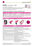
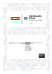
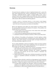
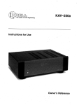
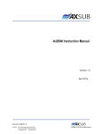
RedMax - Revolution E X P L O S I O N P R O O F Electrical, explosion proof rotary actuators - size S On-off / 3-pos , 24..230 VAC/DC, 95° angle of rotation incl. 5° pretention 5/10 Nm - 15/30 Nm without and 5/10 Nm - 15 Nm with safety operation (spring return) ATEX-tested in acc. with RL 94/9/EG for zone 2 and 22. RedMax- 5.10 RedMax-15.30 RedMax- 5.10 - F RedMax- 15 - F RedMax- ... - S/SF RedMax- ... - VAS RedMax- ... - CTS Subject to change Compact - Easy installation - Universal - Cost effective - Safe Type Torque Supply Motor running time Spring return Control mode Feedback Wiring diagram RedMax -5.10 5 Nm & 10 Nm 24..230VAC/DC 3/15/30/60/120 sec. at 90° without On-off, 3-pos SB 1.0 RedMax-15.30 15 Nm & 30 Nm 24..230VAC/DC 3/15/30/60/120 sec. at 90° without On-off, 3-pos SB 1.0 RedMax- 5.10 - F 5 Nm & 10 Nm 24..230VAC/DC 3/15/30/60/120 sec. at 90° 3 or 10 sec. at 90° On-off, 3-pos SB 2.0 RedMax- 15 - F 15 Nm 24..230VAC/DC 3/15/30/60/120 sec. at 90° 3 or 10 sec. at 90° On-off, 3-pos SB 2.0 RedMax- ... - S/SF Type as above but with 2 integral, potential free aux. switches, switching at 5° and 85° angle of rotation, 2 xEPU, max.24V/3A, 230V/0,25A SB 3.5 RedMax- ... - VAS Type as above but with stainless steel housing (AISI 316) for aggressive ambient (12x12 shaft, shaft manual override, cable glands and hollow rivet nickel-plated) RedMax- ... - CTS Type as above but with Al housing and amercoat painting (12x12 shaft connenction, shaft manual override, cable glands and hollow rivet nickel-plated) Application Damper Ball valve Throttle valve Description size S Highlights The new RedMax actuators are a revolution for safety and shut-off dampers, VAV systems, ball valves, throttle valves and other motorized applications for HVAC systems, in chemical, pharmaceutical, industrial and Offshore-/Onshore plants, for use in EEx-areas zone 2 (gas) and zone 22 (dust). Highest protection class (ATEX) and IP 66 protection, small dimensions, only 3,5 kg weight, universal functions and technical data, an integrated heater and an optional stainless steel housing guarantee safe operation even under difficult environmental conditions. High quality brushless motors guarantee long life. All actuators are programmable and adjustable on site. Special tools or equipment are not required. 5 motor running times and 2 torques as well as 2 spring return times - according to the actuator type - are selectable or adjustable on site. The integrated universal power supply is self adaptable to input voltages in the range of 24 to 230 VAC / DC. The actuators are 100% overload protected and self locking. RedMax-...-F actuators are equipped with spring return fails safe function Standard shaft connection is a double squared direct coupling with 12 x 12 mm Different accessories are available to adapt aux. switches, terminal boxes or adaptations for ball vlaves and throttle valves. u u u u u u u u u u u u u u u u u u u u For all type of gas, mixtures, vapours and dust for use in zone 2 and 22 Universal supply unit from 24 to 230 V - AC/DC 5 different motor running times (3-15-30-60-120 sec./90°), adjustable on site 2 different spring return running times (3-10 sec./90°), selectable on site On-off and 3-pos control with or without spring return function 5 - 10 - 15 - 30 Nm actuators in the same size (S) 100 % overload protected, Self locking Compact design and small dimension (l x w x h = 210 x 95 x 80 mm) Direct coupling to the damper shaft with double-squared connection 12 x 12 mm 95° angle of rotation incl. 5° pre-tention Robust aluminium housing (optional stainless steel or amercoat painting) IP 66 protection Simple manual override include + preparation for comfortable manual override Gear made of stainless steel and sinter metal Only 3,5 Kg weight Integral heater for ambient temperatures down to -40°C Integral safety temperature sensor Integral equipment for manual adjustment (push button, lamp, switch) Preparation for adaptable aux. switches type RedSwitch Range of accessories Schischek GmbH Germany D-90579 Langenzenn, Mühlsteig 45, Gewerbegebiet V, Tel. ++49 (0)9101-90810, Fax ++49 (0)9101-908177, Email [email protected] www.schischek.com RedMax-5.10 RedMax-15.30 RedMax-5.10-F RedMax-15-F RedMax-..-S/SF RedMax-..-VA/-CT Special makes Technical data RedMax-5.10 Torque motor Torque spring return (F) Dimension of external torque Supply voltage/Frequency Dimension Protection class Angle of rotation and indication Working direction Motor running time 3 sec. mode - motor Motor Spring return (F) Spring return running time (F) 3 sec. mode - spring return Safety operations at 10 sec (F) Safety operations at 3 sec (F) Response time spring return Control mode Axle of the actuator Electrical connection Diameter of cable Cable gland Manual override 5 / 10 Nm selectable on site 15 / 30 Nm selectable on site 5 / 10 Nm selectable on site 15 Nm without F without F min. 10 Nm min. 15 Nm above mentioned torques are min. torques in blocked position, external torque should be max. 80 % of max. actuator torque but min. 3 Nm 24...230 VAC/DC, + 15 % / - 20% , self adaptable, Frequency 50...60 Hz +/- 20 % max. starting currents see table (in acc. with voltage, I start >> I rated), max. 20 W blocking position, approx. 16 W for heater class I (grounded) 95°, incl. ~ 5° pre-tention, mechanical value indication selectable by left/right mounting to the damper/valve shaft 3 / 15 / 30 / 60 / 120 sec. at 90° selectable on site In acc. with the supply voltage rand external torque 3 to 4 sec at 90° angle of rotation brushless DC Motor without F without F spring return in the event of loss of power spring return in 3 sec., or 10 sec. at 90°, selectable on site without F without F without F without F in acc. with external torque 3 to 4 sec. at 90° angle of rotation without F without F min. 10.000 in acc. with construction of damper and ambient without F without F min. 1.000 in acc. with construction of damper and ambient up to 1 sec. after power failure On-off and 3-pos in acc. with wiring, selectable on site double squared 12 x 12 mm, direct coupling, 100 % overload protected cable, ~1 m, diameter of wires 0,5 mm², for connection inside hazardous areas an EEx-e terminal box is required! ~ Æ 7,1 mm ~ Æ 7,4 mm ~ Æ 7,4 mm ~ Æ 7,1 mm M16 x 1,5 standard Manual override only if supply voltage is cut, use delivered socket wrench, slow motion, enogh torque/force is required Attention: with manual operation of actuators with spring return danger of injury exists, with release/let go the hexagonal spanner. integral heater, controlled, for ambient temperature down to - 40°C Aluminium die cast housing, painted (optional in stainless steel version AISI 316 - type ..-VAS, amercoat painting type ..-CTS) l x w x h 210 x 95 x 80 mm, for diagramm see extra information ME ~ 3,5 Kg Aluminium housing (stainless steel ~ 7 Kg) storage temp. - 40..+ 70°C, working temperature - 40..+ 40°C at T6 and - 40...+ 50°C at T5, humidity in acc. with EN 60335-1 Integral heater Housing material Dimensions Weight Ambients Operation mode at runningtime motor 3 sec. Operation mode ex runningtime motor 15 sec. Self adjustment Maintenance Wiring diagrams (SB) Delivery Parameter at delivery Explosion proof Certification ATEX Approval for gas RedMax-15.30 E X P L O S I O N P R O O F RedMax-5.10-F RedMax-15-F at 3 sec. 10 % ED, max. 1 on-off cycle per minute (must be guaranteed by control system) at 15/30/60/120 sec. 100 % ED if you select 3 sec. and 15 sec. mode for motor you need to start the self adjustment mode. maintenance free, maintenace must be complied with regional standards, rules and regulations SB 1.0 SB 1.0 SB 2.0 SB 2.0 1 actuator, 1 m cable, double squared shaft connection 12x12 mm, 4 screws M 4 x 100, 4 nuts M 4 socket wrench for simple manual override 5 Nm, 30 sec./90° 15 Nm, 30 sec./90° 5 Nm, 30 sec./90° 15 Nm, 30 sec./90° RedMax actuators - size S PTB 04 ATEX 2106 Directive 94/9/EG (ATEX) II3G EEx nC II T6 II3(1)G EEx [ia] IIC gas, mist, vapour, zone 2 Approval for dust II3D IP66 T80°C dust, zone 22 Identification CE Nr. 0158 EMC EMC-directive 89/336/EG Low voltage Low-voltage directive 72/23/EG IP-Protection IP 66 Potential compensation external PA-terminal, 4 mm² Accessories or special solutions - size S RedMax-...-S 2 internal, potential free aux. switches at 5°/85°, 24V/3A, 230V/0,25A, SB 3.5 RedMax-.-VASabove listed types in stainless steel version, housing AISI 316. RedMax-.-CTSabove listed types in Al-housing with amercoat painting, parts nickel-plated RedBox-... Terminal boxes for zone 2, 22. MKK-S mounting bracket for Terminal boxes type RedBox-... direct on actuator RedSwitch 2 external aux. switches, 2 x EPU, adjustable, for zone 2, 22 KB-S clutch for damper shafts Æ 10...20 mm and 10...16 mm. HV-S comfortable manual override for RedMax actuators size S Adaptations various adaptations for dampers/valves on request AR-12-xx Reduction of square damper connection from 12 mm to 11, 10, 9, 8 Schischek GmbH Germany D-90579 Langenzenn, Mühlsteig 45, Gewerbegebiet V, Tel. ++49 (0)9101-90810, Fax ++49 (0)9101-908177, Email [email protected] www.schischek.com RedMax-5.10 RedMax-15.30 RedMax-5.10-F RedMax-15-F RedMax-..-S/SF RedMax-..-VA/-CT Special makes Electrical connection Parameter, Adjustment - Failure indication RedMax actuators are equipped with a universal supply unit working at a voltage range from 24 to 230 VAC/DC. The supply unit is self adjustable to the connected voltage! The safety operation of the spring return function works if the supply voltage is cut. For electrical connection inside hazardous areas an terminal box, certificated in acc. with ATEX is required (e.g. RedBox). Switch - Push button - Lamp for adjustment, behind the blancking plug 10-position switch (S) Wiring diagram RedMax-5.10 and RedMax-15.30 without spring return 3-colour LED On-off and 3-pos SB 1.0 PE 1 2 ! Attention! ! 4 Wiring diagram RedMax-5.10-F and RedMax-15-F (with spring return) 3-pos SB 2.0 + ~ PE a 1 2 b 3 ! Attention! ! If 3 sec. mode is selected for motor and/or spring return, the self adjustment of angle of rotation must be started and operation mode of max. 10% ED must be guaran teed. Never use actuators in this mode without external torque/force. 24 to 230 VAC/DC 5 PA 4 T Example: RedMax-15.30 Requested parameter: Torque 30 Nm Running time motor 30 sec/90° Result: switch position (S) 07 Type Torques RedMax -5.10 RedMax-15.30 RedMax- 5.10-F RedMax- 15-F u u u u Running times 3 sec./90° 15 sec./90° 30 sec./90° 60 sec./90° 120 sec./90° 5 Nm 10 Nm 15 Nm 30 Nm 5 Nm 10 Nm 15 Nm q q Position of switch S u 00 05 u 01 06 u 02 07 u 03 08 u 04 09 Function, adjustment and parameter PA heater ~ Push button(T) b 3 S Parameter selection If 3 sec. mode is selected, the self adju stment of angle of rotation must be started and operation mode of max. 10% ED must be guaranteed. Never use actuators in this mode without external torque/force. 24 to 230 VAC/DC + ~ ~ a E X P L O S I O N P R O O F heater Standard wiring = spring return in ~10 sec. Additional wiring terminal 5 = spring return in ~ 3 sec. Wiring diagram type RedMax-...-S with integral aux. switches Wiring of integral aux. switches SB 3.5 A) Self adjustment of angle of rotation: Switch (S) into position 02 (low torque) or 07 (high torque), then push button (T) for minimum 3 seconds. The actuator will drive into both end positions to be adjusted. LED indicates green. Adjusmtent time needs approx. 60 sec. (30 sec. On, 30 sec. Off). After that switch S into position 00-09 in acc. with the required torque and running time. B) Selection of running time and torque: Put switch (S) into the correct/selected position in acc. to above table. The selected parameter will work at next operation of the actuator. Adjustment can be done even without supply voltage. If supply voltage is available turn switch only if actuator is not running. C) Running time spring return: The running time of 3 or 10 sec. spring return is selected by wiring (see wiring diagramsSB 2.0). D) Additional information for 3-pos operation: a closed, b open = direction I b closed, a open = direction II a and b closed = Motor doesn't work a and b opened = Motor doesn't work Direction (I and II) depends on left/right mounting of the actuator to the damper/valve. You can change direction of the motor by changing electrical wiring terminal 3 and 4. Error indication See extra information EL Integral aux. switches potential free contacts switching at 5° and 85° angle of rotation max. 24V/3A, 230V/0,25A 24 to 230 VAC/DC + ~ ~ 85 ° 5° PE 1 2 3 4 5 1 2 3 4 5 6 PA heater Wiring of the actuator in acc. with actuator type, see wiring diagrams 1.0/2.0 Additional wiring of the integral aux. switches Schischek GmbH Germany D-90579 Langenzenn, Mühlsteig 45, Gewerbegebiet V, Tel. ++49 (0)9101-90810, Fax ++49 (0)9101-908177, Email [email protected] www.schischek.com RedMax-5.10 RedMax-15.30 RedMax-5.10-F Special makes RedMax-15-F RedMax-..-S/SF RedMax-..-VA/-CT E X P L O S I O N P R O O F Mounting instructions and important information for operation and installation Important information for installation and operation A. Installation, commissioning, maintenance The cable of the actuator must be installed in a fixed position and protected against mechanical and thermical damage. In acc. with operation RedMax actuators are maintenance free. Nevertheless maintenace must comply with regional standards, rules and regulations. The actuators must not be opened by the customer. For outdoor installation a protective housing against rain, snow and sun should be applied to the actuator, as well as a constant supply at terminal 1 and 2 for the integral heater. For electrical connection inside hazardous areas a terminal box is requested (e.g. type RedBox). Attention: If the actuator is put out of operation all EEx-rules and regulation must be applied. Example: you have to cut the supply voltage before opening an EEx-e terminal box Mounting on air dampers with double squared shaft connection Details see extra information ME: Mounting on air dampers with clutch Details see extra information ME: B. Shaft connection, selection of running time, heater RedMax actuators are equipped with a direct coupling double squared shaft connection of 12 x 12 mm. For round shafts an adaptor is available (Accessory type KB-S). The housing of the actuator is axially symmetrically built to select open/close direction of the spring return function by left/right mounting. In acc. to the actuator type 5 different motor running times and 2 different spring return running times can be selected on site. The integral heater is for ambient temperatures down to -40°C. C. Working with 3 sec. motor running time See extra information EL. Mounting of quarter turn valves Details see extra information ME: D. 3-pos control mode See extra information EL. E. Spring return Spring return function works if the supply voltage (terminal 1 or 2) is cut. In the event of an electrical interruption, the spring returns to its end position. F. Operation at an ambient temperature below - 20°C See extra information EL. G. Excess temperature In acc. to the ATEX rules and regulations EEx actuators must be protected against excess temperature. An internal thermostat guarantees the temperature class in the event of failure. If this thermostat is working the actuator must be sent to the factory. RedMax actuators are equipped with an additional temperature sensor to stop the actuator before reaching this max. temperature. In this case the failure must be eliminated immediately on site. H. Loss of voltage In switch position 0, 1 and 5, 6 (motor running time 3, 15 sec.) and after voltage interrupts moves the actuator (type 5.10 and 15.30 /-S) in OFF position then the actuators works regarding control signal. RedSwitch - adaptable external aux. switches RedSwitch is an accessory to RedMax actuators size S, fixing directly onto the actuator. RedSwitch are aux. switches with with 2 potential free contacts, adustable on site. The electrical wiring needs an terminal box. RedBox - adaptable terminal box For electrical connection of an RedMax inside the hazar dous area a terminal box is required. RedBox-3P for RedMax-5.10,..-15.30, ..-5.10-F, ..-15-F RedBox-Y/S for RedMax-...-S integral aux. switches To adapt the RedBox direct to the actuator housing an additional accessory type MKK-S is required. Extra information "EL" (see additional data sheet) extra technical information, versions of circuit diagrams and failure indication Extra information "ME" (see additional data sheet) extra technical information, dimensions, installation instruction and illustration D.RM-01.08-S-en-3P 2006-06-14 Schischek GmbH Germany D-90579 Langenzenn, Mühlsteig 45, Gewerbegebiet V, Tel. ++49 (0)9101-90810, Fax ++49 (0)9101-908177, Email [email protected] www.schischek.com ExMax-.. and RedMax-.. extra information EL - size S E X P L O S I O N P R O O F ExMax/RedMax - extra information EL The "EL"-data sheet contains additional information for ExMax and RedMax actuators of the size "S", for the optimization and simplification in regard to planning, installation and initial startup. It provides influences of external factors in reference to the safe initiation of the actuators, as well as technical references and problem solutions (error indication). With the error indication, functions can be examined and different error/problems can be adjusted locally. For additional mechanical data have a look at "extra information ME" u u u u u u Power supply design Design of line cross section 24...48 VAC/DC Wiring alternatives for on-off, 3-pos, BF actuators Wiring alternatives for modulating actuators Use at ambient temperatures down to -20°C / - 40°C ( ) Error indication - problem treatment/solution Power input depending of supply voltage Power supply design The design of the on-site supply, depends on the selected motor running time and selected supply voltage. Accompanying values are "about values", since there can be construction unit dispersions within electronics. The power consumption in the blocking position is run time independently with max. 20 W. The power consumption for the heater is approx. 16W. The heading is running only if the motor is in idle position! The initial starting supply voltage required by the actuators power supply unit is around 2,0 A for about 1 Sec. (Please consider this while concepting the cross section ot the supply line) Voltage 230 V 120 V 48 V 24 V Current Irated Irated Irated Irated Rated current in acc. with motor running time 3/7,5s 15s 30s 60s 120s 0,5 A 0,3 A 0,15 A 0,10 A 0,10 A 0,75 A 0,4 A 0,3 A 0,25 A 0,25 A 2,0 A 0,5 A 0,3 A 0,2 A 0,2 A 4,7 A 1,45 A 0,52 A 0,4 A 0,4 A Dimensioning of the line cross section with 24 ....48 VAC/DC supply voltages Dimensioning/Design of the supply line On long distances between voltage supply and drive, voltage drops occur due to line resistances. As a consequence with 24 VAC/DC the actuator receives a too low tension and does not start. In order to prevent this, the cross section of the inlet line is to be designed/dimensioned accordingly. The accompanying formula allows the calculation of the necessary line cross section, perhabs provides the maximally permitted conduit length utilizing the existing line cross section. Alternatively the secondary voltage can be increased by selecting a transformer. For calcualtion purposses, following characteristics are essential: UV = supply voltage in [V] A = line cross section in [mm²] L = conduit length in [m] Factor 0.0714 = drive-specific factor [Vmm²/m] ( based on the electrical conductivity of electrolytic copper with a coefficient of 56m/Wmm²) Uv [V] 1 mm² 28 1,5 mm² pannel voltage "Uv" [V] line cross section "A" [mm²] terminal box actuator length "L" [m] Formula for max. cable length "L" at cable cross section "A" Formula of needed cable cross section "A" at a cable length of "L" L = A l (Uv-18V) : 0,0714 A = 0,0714 l L : (Uv-18V) Example: A = 1,5 mm², Uv = 24 V Lengthof cable L = 126 m Example: L = 250 m, Uv = 30 V Cross section of A = 1,5 mm² 2,5 mm² 27 26 4 mm² 25 24 23 22 21 20 50 100 150 200 250 300 350 400 L[m] Example: 24 V power supply with wire diameter 1,5 mm² = 126 m Schischek GmbH Germany D-90579 Langenzenn, Mühlsteig 45, Gewerbegebiet V, Tel. ++49 (0)9101-90810, Fax ++49 (0)9101-908177, Email [email protected] www.schischek.com ExMax-.. and RedMax-.. extra information EL - size S E X P L O S I O N P R O O F Wiring alternatives for on-off and 3-pos actuators with spring return ExMax-...-F, ExMax-...-SF, RedMax-...-F, RedMax-...-SF On-off and 3-pos SB 2.0 24 to 230 VAC/DC ~ On-off 1-wire SB 2.1 24 to 230 VAC/DC + ~ ~ a ! Attention ! If you use this type of wiring the heater does not work in case of open contact. 1 2 PE b 3 5 PA 4 1 heater 2 3 Engaging 1 wire On/Off controlls in the 3 sec. modus with spring return is not possible. The actuator can only be ope rated with 1 On/Off function per minute otherwise electronics will be liable to overheating. 5 PA 4 heater Standard wiring = spring return in ~10 sec. Additional wiring terminal 5 = spring return in ~ 3 sec. Attention! ! If 3 sec. mode is selected, the self adjustment of angel of rotation must be started and operation mode of max. 10% ED must be guaranteed. Never operate actuator in the 3 sec mode without an outside load of min. 3 Nm. + ~ a PE ! Standard wiring = spring return in ~10 sec. Additional wiring terminal 5 = spring return in ~ 3 sec. See additional note 3 sec. motor running time Wiring alternatives for BF actuators ExMax-...-BF, RedMax-...-BF On-off 1-wire - spring return + EEx-i circuit Integrated aux. switches max 24V/3A, 230V/0,5A switching at 5° and 85°. Supply at aux. switches must be the same like supply of the actuator on same fuse in case that power is switched. 24...230 VAC/DC + ~ ~ <5° ! Attention ! If you use this type of wiring the heater does not work in case of open contact. PE SB 7.0 O-off/3-pos - spring return + EEx-i circuit EEx-i circuit for passive + potential free push button on site and safety temperature sensor (Type FireSafe accessories) > 85 ° 24...230 VAC/DC + ~ ~ FireSafe SB 7.1 Integrated aux. switches max 24V/3A, 230V/0,5A switching at 5° and 85°. Supply at aux. switches must be the same like supply of the actuator on same fuse in case that power is switched. <5° EEx-i circuit for passive + potential free push button on site and safety temperature sensor (Type FireSafe accessories) > 85 ° FireSafe PE °C °C b a push button push button A B 1 2 3 4 5 6 7 8 9 10 11 1 2 A B 1 PA 2 3 4 6 7 8 9 10 11 1 2 PA heater heater Standard wiring = spring return in ~10 sec. Additional wiring terminal 5 = spring return in ~ 3 sec. Standard wiring = spring return in ~10 sec. Additional wiring terminal 5 = spring return in ~ 3 sec. On-off 1-wire - spring return + EEx-d limiter 24...230 VAC/DC + ~ ~ ! Attention ! EXC-DS1/VA <5° °C PE SB 7.2 > 85 ° The intrinsic safe circuit must be closed otherwise the actuator is unable to work! Limiter Push button Values of the EEx-i circuit U0 I0 P0 Ci Li Integrated aux. switches max 24V/3A, 230V/0,5A switching at 5° and 85°. Supply at aux. switches must be the same like supply of the actuator on same fuse in case that power is switched. If you use this type of wiring the heater does not work in case of open contact. A C0 L0 = = = = = 10,6 V 11 mA 30 mW 0 0 IIC IIB IIA 830 nF 3,7µF 4,5 µF 2 mH 5 mH 10 mH B 1 5 2 3 4 5 6 7 8 9 10 11 1 2 PA heater ! Attention! ! If 3 sec. mode is selected, the self adjustment of angel of rotation must be started and operation mode of max. 10% ED must be guaranteed. Never operate actuator in the 3 sec mode without an outside load of min. 3 Nm. Engaging 1 wire On/Off controlls in the 3 sec. modus with spring return is not possible. The actuator can only be ope rated with 1 On/Off function per minute otherwise electronics will be liable to overheating. See additional note 3 sec. motor running time Standard wiring = spring return in ~10 sec. Additional wiring terminal 5 = spring return in ~ 3 sec. Schischek GmbH Germany D-90579 Langenzenn, Mühlsteig 45, Gewerbegebiet V, Tel. ++49 (0)9101-90810, Fax ++49 (0)9101-908177, Email [email protected] www.schischek.com ExMax-.. and RedMax-.. extra information EL - size S E X P L O S I O N P R O O F Wiring alternatives for modulating actuators with or without spring return ExMax-...-Y.., RedMax-...-Y.. Modulating with/without spring return Self adjustment: To adjust the signal input/output to the Angle of rotation of the damper/valve the button T must be pushed for minimum 3 sec. + ~ YmA YVDC T 24...230 VAC/DC ~ SB 5.0 VDC/mA 24...230 VAC/DC ~ UmA UVDC PE SB 5.1 Self adjustment: To adjust the signal input/output to the Angle of rotation of the damper/valve the button T must be pushed for minimum 3 sec. + ~ YmA YVDC T Modulating or 3-pos with/without spring return VDC/mA UmA UVDC PE a b I I A B 1 2 3 4 5 1 2 3 4 5 6 heater Selection of running time for spring return: Standard wiring = spring return in ~10 Sek Additional wiring terminal 5 = spring return in ~ 3 Sek A B 1 PA 2 3 4 5 1 2 3 4 5 6 heater Reverse function: I bridge 3--4 reverse input and output signals. Selection of running time for spring return: Standard wiring = spring return in ~10 Sek Additional wiring terminal 5 = spring return in ~ 3 Sek PA Reverse function: I bridge 3--4 reverse input and output signals. Function of switch a and b: - a closed, On (Off) - in acc. to left/right mounting ot the actuator - b closed, Off (On) - in acc. to left/right mounting ot the actuator 3-pos with/without spring return, plus feedback Self adjustment: To adjust the signal input/output to the Angle of rotation of the damper/valve the button T must be pushed for minimum 3 sec. + ~ YmA YVDC T 24...230 VAC/DC ~ SB 5.2 24...230 VAC/DC ~ VDC/mA PE SB 5.3 Self adjustment: To adjust the signal input/output to the Angle of rotation of the damper/valve the button T must be pushed for minimum 3 sec. + ~ T Modulating with/without spring return, no feedback VDC/mA UmA UVDC PE a I A B 1 2 3 4 5 1 heater Selection of running time for spring return: Standard wiring = spring return in ~10 Sek Additional wiring terminal 5 = spring return in ~ 3 Sek 2 3 4 5 6 PA Reverse function: I bridge 3--4 reverse input and output signals. b I A B 1 2 3 4 5 1 2 heater Selection of running time for spring return: Standard wiring = spring return in ~10 Sek Additional wiring terminal 5 = spring return in ~ 3 Sek 3 4 5 6 PA Reverse function: I bridge 3--4 reverse input and output signals. Function of switch a and b: - a closed, On (Off) - in acc. to left/right mounting ot the actuator - b closed, Off (On) - in acc. to left/right mounting ot the actuator 3-sec. mode, 3-pos-operation, heating by low ambient temperatures I. Operation with 3 sec. motor running time mode Note following at 3 sec. motor running time: 1. The 3 sec. motor running time mode is only in switch position 0 and 5 and at a constant supply voltage on terminals 1 and 2 which must be in minimum for 1 minute applied available. 2. The actuator opens at voltage on terminal 3 (resp. closes), and closes at voltage on terminal 4 (resp. opens ) depending on mounting position of the actuator. 3. The max. duty ratio is 10 % resp. 1 cycle / minute. Between two fully cycles to the same direction there must be a minimum intermission of 1 minute. The actuator is blocked if the break time is less than 1 minute. The release for the next cycle is made automatically by an internal timing relay. 4. Same function is applied on spring return actuators. Faile safe operation is regarded same as a motor running cycle. 5. If its tried to use the 1 wire On/Off methode in switch position 0 and 5, software changes the running time temporarily and automatically to 15 sec. motor running time to protect the actuator for overheating due to uncontrolled duty ratio. 6. The actuator must be operated with an outside load of at least 3 Nm. 7. After installing the actuator to the damper/armature an automatic alignment has to be accomplished, in order to obtain a gentle blockade/stop. This function protects the damper/armature by reducing the end positions/blockade speed in order to avoid mechanical overload. The actuator alignes specifically once with 30 Sec/90° onto each position, recognizes the blockade position in order to reduce the motor performance during operation briefly before reaching the end /blockade position. II. 3-pos operation ExMax (RedMax) actuators are in the best way suitable for the 3-pos operation.To protect such elements as gears and mounting elements against harmful influences like minimum pulse time, ExMax (RedMax) actuators are protectet via internal electronics. The internal electronic permits 20 impulses with < 0.5 > sec. cyclic duration, afterwards at least 1 impulse > 1 sec. must follow. If clocked with more than 20 impulses each < 1 sec. the actuator will adjust into a suspend mode.There after a reset is mandadory and will be achieved by briefly switching of the supply voltage for about 2 sec.. The controll unit has to be parameterized in order to be set within the above mentioned duration limits. III. Use at low ambient temparature below -20°C All ExMax (Redmax) actuators are equipped with a regulated integrated heating device designed for employments down to -40°C ambient temperature. The heater will be supplied automatically by connecting the constant voltage supply on the clamps 1 and 2. Following parameters are to be considered by ambient temperaure < 10°C: 1. After mounting the actuator must bei immediately electrically connected. 2. The actuator will only be activated after the operating temperature has reached at least -20°C . 3. The adjustment options are only ensured after this heating up period. Schischek GmbH Germany D-90579 Langenzenn, Mühlsteig 45, Gewerbegebiet V, Tel. ++49 (0)9101-90810, Fax ++49 (0)9101-908177, Email [email protected] www.schischek.com ExMax-.. and RedMax-.. extra information EL - size S E X P L O S I O N P R O O F Error indication Error/Symptom Reason Solution 01 Actuator does not work LED does not lights l l No power supply attached The actuator is operated beyond ex-prevention ambient temperature specifications and the internal temperature sensor did irreversibly shut down operations l l Attache power supply and turn on Because of inadmissable operation the actuator drove out of safety relevant reasons into an irreversible condition and must be exchanged. Accompanying new installation the ambient temperature has to be reduced accordingly 02 Actuator does not work LED lights red l The actuator is operated by a too high ambient temperature and the internal temperature sensor responded l Shut off actuator and let temperature decrease, reduce ambient temperature by suitable measures e.g. ventilation or other mounting position of the actuator 03 Actuator does not work LED lights green l l 3-Pos control signal is wired on both entrances Required torque is greater than actuators torque l l l Control signals are not attached or attached on a wrong conductor Actuator is incorrect mounted and is blocked by an external stop unit l Readjust/correct circuit Adjust a higher torque at the actuator if possible otherwise exchange for a type with higher torque. Examine rule and adjusting signal in accordance with attached diagram l Actuator is clocked with more than 20 impulses <0,5 per sec. and therefore adjusted into suspend mode l l Interchanged supply lines l Wire 1 must be (-, N) and wire 2 (+, L) l l Dismount actuator and testdrive without load for operability. Install actuator accordingly that the power transmissions runs without external blockade or torsion Switch off supply voltage for at least 2 sec. thereby a reset is conducted Readjust controller in order to extend control pulses 04 Acuator does not work LED is red blinking l The actuator has been mounted by temperatures of less than -20°C and did not reach is operating temperatur of at least -20°C. l l Ensure that a constant voltage supply on conductor 1--2 is existing. Wait until the required operating temperature is achieved by the actuators internal heating system.The actuator will start operating independently 05 Spring return funktion is 10 sec./90°, should however amount to 3 sec./90° l Bridge 2 --5 is not established l Bridge conductor 2 of the constant voltage supply with conductor 5 06 Spring return funktion is 3 sec./90°, should however amount to 10 sec./90° l Bridge 2 --5 is established l Disconnect bridge 07 Actuator does not start after more than 2 briefly following adjusting functions in the 3 sec. mode where set l The maximal permissable cyclic duration of 10% ED was not complied to, the actuator is in a safety disconnection mode l Wait approx.1 minute until internal electronics cool down to operating temperature. 08 Y-drive in the 3-pos mode can not gear into intermediate positions l The conversion of constant mode on 3-pos-modus was not set l Recalibrate the actuator in accordance with assembly instructions 09 Actuator sits diagonally on the squared damper shaft l The actuators have an angle of rotation of 95° inclusive 5° pre-tention. While assembling the preloading was not considered l Dismount actuator of the damper, use the enclosed socket wrench to draw up approx. 5° over the hand operated control device before remounting on the damper shaft. Consider additional information ME of the assembly instructions 10 Actuator is with clamp stand KBS actuated installed onto damper shaft and does only partly or not at all drive l Provided that the electrical basic conditions specified above are fullfilled, the anti- twist plate could be so installed that the actuator blocks itself due to the twisted and not centric shaft connection and therefore interlocks l Loosen the anti-twist plate and remount that the actuator can implement an easy oscillationg motion over its angle of rotation 11 A modulating actuator (Y) works with reduced angle of rotation and already reaches its end positions before O V/4 mA, respectively before 10V/20mA. l At start up no self adjustment of angle of rotation was accomplished l Accomplish self adjustment of angle of rotation in accordance with assembly instruction 12 LED flashes irregularly and actuator does not work l Actuator does not receive sufficient supply voltage l Increase line cross section or increase tension at the transformer/power suply unit l Cable to long, voltage drop in the supply line to large l Increase line cross section or increase tension M.EZ-01.05-S-en-Zusatzinfo EL 2008-01-16 Schischek GmbH Germany D-90579 Langenzenn, Mühlsteig 45, Gewerbegebiet V, Tel. ++49 (0)9101-90810, Fax ++49 (0)9101-908177, Email [email protected] www.schischek.com ExMax-.. and RedMax-.. extra information ME - size S E X P L O S I O N P R O O F ExMax/RedMax - extra information ME The "ME"-data sheet contains additional information for ExMax and RedMax actuators of the size "S", for the optimization and simplification in regard to planning, installation and initial start up. It provides influences of external factors in reference to the safe initiation of the actuators. In particular it represents the installation, as well as different dampers, fire protection dampers and armatures. Additionally describing different accessory elements and their mounting to the actuator. For additional electrical data have a look at "extra information EL" u u u u u u u u Dimension, drill template Control elements: switch - push button - LED Outdoor installation Mounting using form-fitting shaft connection (square shaft) Mounting using clamp mounting (round shaft) Mounting on butterfly valves and ball valves Mounting on fire dampers Mounting ExBox (RedBox), ExSwitch (RedSwitch) Dimensions - drill template Dimension size S Dimension in mm 118,5 30 30 14 60 inl. radius of bend for the cable 210 Side L 95 80 74 Side R 6 x Æ 4,4 6xM4 Double sqaured 12 x 12 mm Control elements: switch - push button - LED Specification All ExMax and RedMax actuators are equipped with a 10 position switch a push button and a multicolor LED for calibration. These control elements are to be found cablelaterally behind the two middle sectioned dummy plugs. For operation these must be removed. The calibration can be achieved despide lining up tension at the actuator. The explosion prevention is not impaired thereby. However it has to be of great concern that the dummy plugs must be rescrewed in order to comply with the IP-protection class. The operation of the switch and button has to be done by means of a small screwdriver. Force with strong pressure and /or rotation is to be avoided in any case, since otherwise control electronics can be damaged irreparably. By bad visibilities a flashlight (certified within the EX-range) should be used. Attitudes of torque and running time can be achieved also before mounting. The adjustment of angle of rotation can be started only with an outside load and accurate mounting. Switch - push button - LED for programming, behind dummy plug S 10-position switch (S) Push button (T) T 3-colour LED Outdoor installation Specification When mounting actuator outdoors it has to be certain that the actuator is protected against direct sun exposure (heat and UV), rain and snow by employing an enclosure roof. Supply voltage is to be applied immediately after mounting in order to assure integrated heating at start. Since explosion proof actuators must have internal safety temperature limiters, these may not be exposed neither at storage nor during operation to a too high temperature. Otherwise the limiters could respond and switch of the actuator irreversibly. RST Schischek GmbH Germany D-90579 Langenzenn, Mühlsteig 45, Gewerbegebiet V, Tel. ++49 (0)9101-90810, Fax ++49 (0)9101-908177, Email [email protected] www.schischek.com ExMax-.. and RedMax-.. extra information ME - size S E X P L O S I O N P R O O F Mounting instruction for ExMax and RedMax actuators size S on air dampers Specification ExMax and RedMax actuators size S are equipped with a 12 x 12 mm (double square) shaft connection. The form-fitting shaft connection is the securest connection between damper shaft and actuator because slipping or slipping through is avoided compared to the force-fit clamp-connection. The actuator will be connected firmly by means of four screws M 4 x 100 (scope of supply) to the damper. For the connection to round damper shaft or square damper shaft with smaller or larger 12x12 mm an optional mounting clamp (type KB-S) for tensionally locked connections is available. Form fitting mounting on square damper shaft Mounting clamp type KB-S Dimension damper shaft A Dimension squared damper shaft Length A Dimension A in acc. with indicator 1. Actuator without indicator A = no limit 2. Actuator with indicator, no accessories A < 65 mm 12 x 12 mm Dimension round damper shaft A A Æ 10...20 mm 10..16 mm Length A < 25 mm 1. Pre-assembly clamp Length A < 25 mm 2. Fixing the clamp 2x M4 x 100 HV 3. Pre-assembling mounting bracket 4. Mounting to the damper 4 screws M4 x 100, as well as a socket wrench, are part of delivery for ExMax/RedMax actuators size "S". For damper shafts 9 x 9, 10 x 10 or 11 x 11 mm reducing bush are optional available. Mounting instructions form-fitting shaft connection Mounting instructions for mounting clamp It is to be considered that the actuators have a total angle movement of approx. 95° in order to realize a pre-tention on the damper. Therefore the actuator sits tilted on the damper shaft. In order to prevent this and to assure pre-tention to the damper the driving shaft has to be adjusted mechanically before connecting to the damper shaft. The provided socket wrench serves for the mechanical adjustment over the hand-operated control socket HV. The actuators are axially symmetrically developed. In case of spring return function the safety postion must be selected by turning the actuator 180°. Mounting: 1. Affix tap hole M4 (in accordance with drill template) on the damper or to a mounting bracket. 2. Adjust drive shaft of the actuator with the socket wrench that the drive stands perpendicular to the damper before pluging actuator on to the damper shaft. 3. Plug actuator onto damper shaft and fix diagonally with 2 screws. 4. Remove the socket wrench. 5. Pivot and tighten the remaining screws. Note: the drive shaft is selflockingly produced and may only be mechanically adjusted either with the provided socket wrench or the optional accessory "HV-S" manual override. External applied force to the shaft can lead to mechanical damage of the actuator. The actuators are axially symmetrically developed. In case of a spring return function the safety position must be selected by turning the actuator 180°. Mounting 1. Insert u-bold connection into drive-shaft and screw the bold from the opposite side tight with the socket wrench. 2. Screw in two screws functioning as an anti twist locking device. 3. Install mounting bracket at the damper. 4. Plug the actuator to the damper shaft, adjust the actuator in the mounting brackets position and tighten the damper shaft with a wrench socket via the u-bold connection. Attention! The actuator must be installed in such a way that it can implement an easy oscillating motion in the mounting bracket for the reconciliation of the not centric connection. Note: the drive shaft is selflockingly produced and may only be mechanically adjusted either with the provided socket wrench or the optional accessory "HV-S" manual override. External applied force to the shaft can lead to mechanical damage of the actuator. Schischek GmbH Germany D-90579 Langenzenn, Mühlsteig 45, Gewerbegebiet V, Tel. ++49 (0)9101-90810, Fax ++49 (0)9101-908177, Email [email protected] www.schischek.com ExMax-.. and RedMax-.. extra information ME - size S E X P L O S I O N P R O O F Mounting instructions for ExMax and RedMax actuators size S on butterfly valve and ball valve Specification ExMax and RedMax actuators of the size S are equiped with a 12x12 mm (double square) form-fitting shaft connection. For mounting to butterfly valves or ball valve a special mounting bracket in acc. with DIN EN ISIO 5211 is required. Since this standard provides only certain basic conditions there can be substantial geometrical differences between armatures which require a special adaption. Mounting to a ball valve Mounting to a butterfly valve 4x 4x Mounting instructions for ExMax and RedMax actuators Size S on fire dampers Specification ExMax and RedMax actuators of the size S are equipped with a 12x12 mm (double square) form-fitting shaft connection. The form-fitting shaft connection is the securest connection between damper shaft and actuator. The actuator is fixed with four screws directly to the fire damper and/or fixed to a mounting bracket. ExMax-...-BF and RedMax-...-BF actuators integrate an intrinsically safe circuit in order to connect a FireSafe sensor which works like a temperature limiter. Fire damper Assembly It is to be considered that the actuators have a total angle of rotation of approx. 95° in order to realize a pre-tention on the damper. Therefore thr actuator sits tilted on the damper shaft. In order to prevent this and to assure pre-tention to the damper the driving shaft has to be adjusted mechanically before connecting to the damper shaft. The provided socket wrench serves for the mechanical adjustment over the hand-operated control socket HV.The actuators are axially symmetrically developed. In case of a spring return function the safety postion must be selected by turning the actuator 180°. Mounting: 1. Affix tap hole M6 (in accordance with drill drill template) on the damper or to a mounting bracket. 2. Adjust drive shaft of the actuator with the socket wrench that the drive stands perpendicular to the damper before pluging actuator on to the damper shaft. 3. Plug actuator onto damper shaft and fix diagonally with 2 screws. 4. Remove the socket wrench. 5. Pivot and tighten the remaining screws. 6. Mount temperatur limiter type Fire Safe 7. Mount terminal box 8. Wire connect actuator and sensor in the terminal box Note: the drive shaft is selflockingly produced and may only be mechanically adjusted either with the provided socket wrench or the optional accessory "HV-S" manual override. External applied force to the shaft can lead to mechanical damage of the actuator. Schischek GmbH Germany D-90579 Langenzenn, Mühlsteig 45, Gewerbegebiet V, Tel. ++49 (0)9101-90810, Fax ++49 (0)9101-908177, Email [email protected] www.schischek.com ExMax-.. and RedMax-.. extra information ME - size S E X P L O S I O N P R O O F Mounting of terminal boxes type ExBox (RedBox) via mounting bracket type MKK-S to the actuator (accessory) Specification Mounting bracket MKK-S can be mounted every 90° 1. Screw mounting bracket MKK-S to the actuator (A) then terminal box to the mounting bracket (B) schrauben (B) 2x (A) 2x Terminal box mounted above the actuator Terminal box mounted beside the actuator Mounting of ExSwitch (RedSwitch) accessory to the actuator Specification 1. Put the squared connection part to the actuator, then mount ExSwitch(RedSwitch) and fix it with 4 screws 2. ExMax (RedMax) with mounted ExSwitch (RedSwitch) 4x M.MZ-01.01-S-en-Zusatzinfo ME Schischek GmbH Germany D-90579 Langenzenn, Mühlsteig 45, Gewerbegebiet V, Tel. ++49 (0)9101-90810, Fax ++49 (0)9101-908177, Email [email protected] www.schischek.com