1
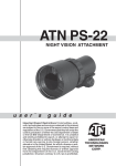
ATN PS-22
NIGHT VISION FRONT SIGHT
operator’s manual (ATN PS-22) Revision 6 - MArch 2011
operator’s manual
Important Export Restrictions ! Commodities,
products, technologies and services contained in
this manual are subject to one or more of the export
control laws and regulations of the U.S. Government
and they fall under the control jurisdiction of either the
US Department of State or the US BIS-Department
of Commerce. It is unlawful and strictly prohibited
to export, or attempt to export or otherwise transfer
or sell any hardware or technical data or furnish any
service to any foreign person, whether abroad or
in the United States, for which a license or written
approval of the U.S. Government is required, without
first obtaining the required license or written approval
from the Department of the U.S. Government having
jurisdiction. Diversion contrary to U.S. law is prohibited.
Register your product warranty online at
www.atncorp.com/warranty
The information in this manual furnished for information use only, is subject to
change without notice, is not to be construed as a commitment by ATN Corp.
ATN Corp. assumes no responsibility or liability for any errors or inaccuracies
that may appear in this book.
© 2011 ATN Corp. All right reserved.
SAFETY SUMMARY
STUDY CAREFULLY THIS MANUAL BEFORE
TURNING ON AND OPERATING THIS PRODUCT.
CAUTIONS
The ATN PS-22 night vision front sight is a precision electrooptical instrument and requires careful handling. To provide
safe use of the sight the following instructions should be
observed:
•Do not dismantle the sight.
•Keep the sight clean; protect it from moisture, sharp temperature drops and shocks.
•Be careful not to touch the glass surfaces. If you put fingerprints on, or contaminate the glass surfaces, use only clean
and soft materials to clean it.
•Protect the sight from a light overloading. Do not turn the sight
on in daylight with the Front Lens Cap off. Do not point the sight
at the bright light source (a fire, car headlights, lanterns, street
lamps, room lights, etc.).
•Do not leave the sight in on position during stops in operation.
•Remove the battery from the sight for the period of storage.
C aution:
This product contains natural rubber latex
which may cause allergic reactions.
a
NOTES
• Do not test the device in daylight conditions even with the
daylight filter/lens cap on for more than ten (10) minutes.
• To protect the device from damage do not direct it to the
bright light sources (a fire, headlights of the automobile, lanterns, etc.).
b
Equipment Limitations
To avoid physical and equipment damage when using the
ATN PS-22, carefully read and understand the following equipment limitations.
• The equipment requires some night light (moonlight, starlight,
etc.) to operate. The level of equipment performance depends
upon the level of light.
• Night light reduces by passing through the clouds, while operating under trees, at building shadows, etc.
• The equipment is less effective when viewing into shadows
and other darkened areas.
• The equipment is less effective when viewing through the rain,
fog, sleet, snow or smoke.
• The equipment will not “see” through the dense smoke.
c
TABLE OF CONTENTS
i
pg.
SAFETY SUMMARY
a
SECTION I. INTRODUCTION
1.1.General
1.1.1.Scope
1.1.2.Reports
1.1.3.Storage
1.1.4.Warranty
1.2. Description and Data
1.2.1.Description
1.2.2.PS-22 Standard Components
and Optional Equipment
1-1
1-2
1-2
1-2
1-2
1-3
1-5
1-5
1-8
SECTION II. OPERATING INSTRUCTIONS
2.1. Installation Procedures
2.1.1. Quick Release Mount
2.1.2.Attachment to Day Scope Objective 2.1.3. Extender Focus Knob
2.2. Operating Procedures
2.2.1.General
2.2.2.Controls
2.2.3.Operating Procedures
2.2.4.Stowage of PS-22
2.3. Installation and Use of Accessories
2.3.1. 7/8” Weaver Mount
2.3.2.Remote Control
2.3.3.Picatinny Rail
2.3.4.Platform Ring
2.3.5.Long Rail Adapter
2.3.6.B.A.M. System
2.3.7. IR450 Illuminator
2.3.8.Day Scope Light Suppressor
2-1
2-2
2-2
2-3
2-7
2-8
2-8
2-8
2-10
2-11
2-12
2-12
2-12
2-13
2-14
2-14
2-14
2-16
2-18
SECTION III. OPERATIONAL DEFECTS3-1
3.1. Zeroing Operational Defects
3-2
3.1.1. Shading
3-2
3.1.2. Edge Glow
3-3
3.1.3. Flashing, Flickering, or Intermittent Operation
3-3
3.1.4. Cosmetic Blemishes
3-3
SECTION IV. MAINTENANCE INSTRUCTIONS
4-1
4.1. Preventive Maintenance Checks
and Services (PMCS)
4-2
4.1.1.Purpose of PMCS
4-2
4.1.2.PMCS Procedures
4-2
4.2. Troubleshooting
4-5
4.2.1.General
4-5
4.2.2.Troubleshooting Procedures
4-5
4.3. Maintenance Procedures
4-7
4.3.1. PS-22 Maintenance
4-7
4.3.2.Cleaning Procedures
4-7
4.3.3.Tube Maintenance / Replacement
4-8
Appendix A. Estimation of Ambient
Illumination Level
A-1
Appendix B. Spare Parts List
B-1
Appendix C. How to select Scope Mounting System C-1
For Technical Information
INFO-1
ii
iii
SECTION I
introduction
1-1
1.1 General Information
1.1.1.Scope
This manual contains instructions for use in operating and maintaining the ATN PS-22 Night Vision Front Sight. Throughout this
manual, the ATN PS-22 will be referred to as the sight or the
PS-22.
1.1.2.Reports
Reports from the user on recommendations for improvements are
encouraged. Send reports to the address below.
American Technologies Network Corp.
1341 San Mateo Avenue
South San Francisco, CA 94080
(800) 910-2862
(650) 989-5100
(650) 875-0129 fax
www.atncorp.com
[email protected]
1.1.3.Storage
Storage of the PS-22 should be done in the factory packing and
after a thorough PMCS as outlined in Section 4 of this manual.
This will ensure the sight remains in mission ready condition during storage. Battery should be stored separately from the sight.
The PS-22 should not be placed on the floor, in any area exposed
to high temperatures or direct sunlight. Presence of acid and alkaline vapor, as well as of other aggressive admixtures in the air
is unacceptable.
1-2
1.1.4.Warranty
2 Year Product Warranty
This product is guaranteed to be free from manufacturing defects in
material and workmanship under normal use for a period of 2 (two)
years from the date of purchase. In the event a defect that is covered
by the foregoing warranty occurs during the applicable period stated
above, ATN, at its option, will either repair or replace the product, and
such action on the part of ATN shall be the full extent of ATN’s liability,
and the Customer’s sole and exclusive remedy. This warranty does not
cover a product (a) used in other than its normal and customary manner; (b) subjected to misuse; (c) subjected to alterations, modifications
or repairs by the Customer of by any party other than ATN without prior
written consent of ATN; (d) special order or “close-out” merchandise or
merchandise sold “as-is” by either ATN or the ATN dealer; or (e) merchandise that has been discontinued by the manufacturer and either
parts or replacement units are not available due to reasons beyond the
control of ATN. ATN shall not be responsible for any defects or damage
that in ATN’s opinion is a result from the mishandling, abuse, misuse,
improper storage or improper operation, including use in conjunction
with equipment which is electrically or mechanically incompatible with
or of inferior quality to the product, as well as failure to maintain the
environmental conditions specified by the manufacturer.CUSTOMER
IS HEREBY NOTIFIED THAT OPERATION OF THE EQUIPMENT
DURING DAYLIGHT HOURS OR UNDER ANY EXCESSIVE LIGHT
CONDITIONS MAY PERMANENTLY DAMAGE THE INTERNAL
COMPONENTS OF THE UNIT AND SAID DAMAGE WILL NOT BE
COVERED UNDER THIS WARRANTY. This warranty is extended only
to the original purchaser. Any breach of this warranty shall be waived
unless the customer notifies ATN at the address noted below within the
applicable warranty period.
The customer understands and agrees that except for the foregoing
warranty, no other warranties written or oral, statutory, expressed or
implied, including any implied warranty of merchantability or fitness for
a particular purpose, shall apply to the product. All such implied warranties are hereby and expressly disclaimed.
Limitation of Liability
ATN will not be liable for any claims, actions, suits, proceedings, costs,
expenses, damages or liabilities arising out of the use of this product.
Operation and use of the product are the sole responsibility of the Customer. ATN’s sole undertaking is limited to providing the products and
services outlined herein in accordance with the terms and conditions of
this Agreement. The provision of products sold and services performed
by ATN to the Customer shall not be interpreted, construed, or regarded, either expressly or implied, as being for the benefit of or creating
1-3
any obligation toward any third party of legal entity outside ATN and the
Customer; ATN’s obligations under this Agreement extend solely to the
Customer.
ATN’s liability hereunder for damages, regardless of the form or
action, shall not exceed the fees or other charges paid to ATN by
the customer or customer’s dealer. ATN shall not, in any event, be
liable for special, indirect, incidental, or consequential damages,
including, but not limited to, lost income, lost revenue, or lost profit, whether such damages were foreseeable or not at the time of
purchase, and whether or not such damages arise out of a breach
of warranty, a breach of agreement, negligence, strict liability or
any other theory of liability.
Product Warranty Registration
In order to validate the warranty on your product, ATN must receive a
completed Product Warranty Registration Card for each unit or complete warranty registration on our website at www.atncorp.com. Please
complete the included form and immediately mail it to our Service Center: ATN Corporation, 1341 San Mateo Avenue, South San Francisco,
CA 94080.
Obtaining Warranty Service
To obtain warranty service on your unit, End-user must notify ATN service department by calling 800-910-2862 or 650-989-5100 or via e-mail
[email protected] to receive a Return Merchandise Authorization
number (RMA).
When returning please take or send the product, postage paid, with a copy
of your sales receipt to our service center, ATN Corporation at the address
noted above. All merchandise must be fully insured with the correct postage; ATN will not be responsible for improper postage or, missing or damaged merchandise during shipment.
When sending product back, please clearly mark the RMA# on the outside of the shipping box. Please include a letter that indicates your RMA#,
Name, Return Address, reason for service return, Contact information such
as valid telephone numbers and/or e-mail address and proof of purchases
that will help us to establish the valid start date of the warranty. Product
merchandise returns that do not have an RMA listed may be refused or a
significant delay in processing may occur.
Estimated Warranty service time is 10-20 business days. End-user/customer is responsible for postage to ATN for warranty service. ATN will cover return postage/shipping to continental USA end-users/customers after
warranty repair only if product is covered by aforementioned warranty. ATN
will return product after warranty service by domestic UPS ground and/
or domestic mail. Any other requested, required or international shipping
method the postage/shipping fee will be the responsibility of the end-user/
customer.
1-4
1.2.Description and Data
1.2.1.Description
A.Purpose
The PS-22 is an effective night vision system that mounts forward
of an existing riflescope/spotting scope (further referred to as a
scope) adding night vision capabilities to daytime target acquisition platform. Advisable dayscope magnification is 1X to 6X (2.5X
to 4X is optimum). The sight is installed and removed without affecting boresight (permanent boresight alignment).
NOTE
The PS-22 can be installed also forward of viewfinders of various instruments to widen operating illumination range.
B. Principle of Operation
The PS-22 operation is based on the principle of electron-optical
intensification of light. The input fast catadioptric lens collects
available ambient light from source such as the moon, stars and
skyglow and focuses it on the image intensifier tube photocathode. The tube amplifies the light and produces the viewable image projected by the output lens from the tube screen into the
dayscope lens. Thus the sight provides the capability for operator
to see through the scope at night.
C. Features and Limitations
The PS-22 has the following important features:
•Available with 2+, CGT, HPT or 3rd generation image intensifier tube.
•Powered by a single CR 123A battery.
•Adjusts for lens focus.
•Is mounted on MIL-STD-1913/Picatinny rail or dayscope lens.
•Equipped with remote control.
•Is submersible to 10 m for 30 minutes.
•Filled with dry nitrogen to prevent internal fogging.
1-5
The PS-22 is an effective night vision system designed for night
operations but does have following limitations:
•The sight requires some night light (moonlight, starlight, etc.) to
operate. Night light is reduced by such factors as passing cloud
cover and objects that produce shadows.
•The sight is less effective viewing through rain, fog, sleet, snow,
smoke.
•Under starlight conditions low contrast environments (such as
snow-covered territory, sandy deserts, large bodies of water or
grassy hills) degrade visibility thereby disguising or masking
changes in terrain.
•Under too low-light conditions the sight looses some of the resolution that it has under full moon.
Table 1-1. System Data
ITEM
Magnification
DATA
Unity (1X)
Boresight Characteristics:
Accuracy
Factory aligned to ½ MOA or better
Retention
Permanent to within 1 MOA or better
Repeatability
Within ½ MOA
System Resolution subject to Tube Resolution:
1-6
36 to 44 lp/mm
0.38 mrad/lp
45 to 54 lp/mm
0.30 mrad/lp
55 to 64 lp/mm
0.25 mrad/lp
Over 65 lp/mm
0.21 mrad/lp
Table 1-2. Mechanical Data
ITEM
DATA
Dimensions(Length x Width x Height)
150 mm x 80 mm x 72 mm
Weight:
without Battery
0.64 kg
with Remote Control, Light
Suppressor and Battery
0.7 kg
Height of the Sight Axis above Arm Rail:
with Issued Mount
40 mm
Table 1-3. Electrical Data
ITEM
DATA
Battery
123A Lithium
Consumption Current
26 mA
Cell Life at 20 ˚C
50 hours
NOTE
CR 123A batteries are “dead” at 2.5 VDC under load.
Table 1-4. Optical Data
ITEM
DATA
Objective Lens Focal Length
80 mm
Objective Lens F/number
1:1.23
Objective Lens T/number
1:1.8
Focus Range
Field of View
Output Lens Exit Pupil Diameter
10 m to infinity
12˚
21 mm
1-7
Table 1-5. Environmental Data
ITEM
DATA
Operating Temperature
-20 to +50 ˚C
Storage Temperature
-50 to +50 ˚C
Humidity
95 %, 25 ˚C to 40 ˚C for 48 hours
Illumination Required
Natural night illumination (overcast starlight to moonlight)
Immersion
10 m for 30 minutes
1.2.2. PS-22 Standard Components and
Optional Equipment
The PS-22 standard components are shown in Figure 1-1 and presented in Table 1-6.
4
2
6
7
3
1
5
8
11
10
9
12
14
13
15
Figure 1-1. PS-22 Standard Components
Table 1-6. PS-22 Standard Components
ITEM
1-8
DESCRIPTION
QTY
1
Front Lens Cap
1
2
ATN PS-22 Night Vision Front Sight
1
3
Back Cap
1
4
Light Supressor for the scopes with 30-42 mm lens diameter
1
ITEM
DESCRIPTION
QTY
5
Light Supressor for Trijicon ACOG scopes
1
6
Light Supressor for the scopes with 42-63 mm lens diameter
1
7
Remote Control
1
8
CR123A type battery
1
9
IR Illuminator IR450 Kit
1
10
Picatinny Quick Release Mount
1
11
Picatinny Rail
1
12
QRM Wrench
1
13
2.5 mm Allen Key
1
14
Operator’s Manual
1
15
Shipping/Storage Case
1
R450-B4 IR Illuminator Kit is shown in Figure 1-2 and listed in Table 1-7.
1
2
3
4
Figure 1-2. IR450 IR Illuminator Kit
Table 1-7. IR450 Kit
ITEM
DESCRIPTION
QTY
1
IR450-B4 Illuminator
1
2
CR123A type battery
1
3
1,5 mm Allen Key
1
4
IR450 Wrench
1
1-9
Optional items are shown in Figure 1-3 and listed in Table 1-8.
Table 1-8. PS-22 Optional Equipment
ITEM
1
DESCRIPTION
Scope Mounting System #1
PART CODE
ACDNPS22SM01
2
Scope Mounting System #2
ACDNPS22SM02
3
Scope Mounting System #3
ACDNPS22SM03
4
Scope Mounting System #4
ACDNPS22SM04
5
Scope Mounting System #6
ACDNPS22SM06
6
7/8” Weaver Mount
ACDNPS22MWVR
7
Day Scope Light Suppressor
8
Platform Ring
9
Extender Focus Knob
10
Boresight Attachment Mount (BAM)
11
Long Rail Adapter
1 (2, 3, 4, 5)
ACDNPS22LSR
ACWSRTRA
ACDNPS22EFK
ACDNPS22BM01
ACWSLRADPT
6
7
8
9
10
11
Figure 1-3. PS-22 Optional Equipment
1-10
SECTION II
operating instructions
2-1
2.1. Installation Procedures
2.1.1.Quick Release Mount
Quick Release Mount (QRM) is used for fast installation/removing
the PS-22 on MIL-STD-1913/Picatinny rail.
NOTE
Optical axes of the PS-22 and the riflescope should be matched.
Difference of the axes position more than 3 mm is not re-commended. Measure the height of the riflescope axis above the rail.
If the difference in the axis heights of the PS-22 and riflescope is
more than 3 mm it is necessary to replace riflescope mounting
rings or base by proper ones.
Mount Tightness Nut
A
B
Mount Lever
Wrench
Figure 2-1. PS-22 Installed on MIL-STD-1913 Rail
forward of Trijicon ACOG
1. Slide the locking button of mount lever forward (Figure 2-1, arrow
A). Turn the mount lever backwards to open the mount (Figure
2-1, arrow B).
2. Install the sight forward the riflescope on the arm rail as close to
the riflescope as possible. The light suppressor should cover the
riflescope objective lens.
3. Turn the lever forwards pushing and sliding forward locking button to close the mount.
2-2
QR Mount comes factory set to securely fit most standard
MIL-STD-1913/Picatinny mounts. However, there may be some
slight differences in each mount from various manufacturers. You
can loosen or tighten the QRM on your rail by using a 3/8” wrench
and adjust the Mount Tightness Nut.
NOTE
If using weaver rails, please consult your gunsmith for modification to rail.
2.1.2. Attachment to Day Scope Objective
CAUTION
The PS-22 will not attach to those riflescopes/spotting scopes which
have their focusing ring on the hood of the objective lens bell.
Optional Scope Mounting Systems are designed to install the
PS-22 onto the riflescope/spotting scope objective lens.
The Scope Mounting Systems and their inserts differ in attaching
diameters and are supplied on special order with account of the
parameters of the scope. To choose the proper system # and its
correspondent insert refer to the Table 2-1. For example, you will
need the scope mounting system #1 and 25.4 mm insert in order to
mount the PS-22 onto the front lens of Leupold 1.5-5x20 PR.
NOTE
If scope mounting system is used, the issued weapon mount
should be removed.
Installation:
1. Loosen two screws M2x2.5 inside the locking ring (Figure 2-2) of
the scope mounting system. The locking ring must travel easily
along the thread.
2. Rotate the locking ring towards the body of the mounting system
until full stop (the rotating direction is shown with arrow on Figure 2-2). Avoid overtightening.
3. Remove the Back Cap (or Light Suppressor, if it was installed)
from the PS22 output lens and leave it in the storage case.
4. Screw the scope mounting system with insert inside into the
PS22 output lens thread and hand-tighten it.
2-3
locking Ring
INSERT
Screw M2x2.5
Figure 2-2. Scope Mounting System
5. Loosen the fixing nut of the mounting system.
6. Slide the PS-22 with attached mounting system onto the objective lens of the day scope until full stop.
Dayscope Objective Lens
Fixing Nut
Scope Mounting System
Insert
Figure 2-3. PS22 INSTALLED ON DAYSCOPE OBJECTIVE LENS
Desirable Position of the Nut
Figure 2-4. Estimation of the Angle which
the Scope Mounting System Should Be Turned through
2-4
7. Align the seating of the PS22 and its mounting system on the day
scope lens. Decide on the desirable position of the nut and turn the
scope mounting system until you achieve it (see arrow in Figure 2-4).
8. Tighten the fixing nut hard with a screwdriver.
9. Now you may turn the PS22 unit to the optimal position (e.g. function switch placed strictly horizontal or canted), at your discretion.
10. Rotate the locking ring of the scope mounting system towards
the PS22 output lens and tighten it. It will work as a lock nut to fix
the PS22 position on the day scope.
11. Apply a small amount of thread locker on threads and tighten the
two screws M2x2.5 in the locking ring.
Table 2-1. Scope Mounting Systems
Objective
Clear
Scope
Lens Diame- Aperture of
Mounting
ter (Insert Objective
System #
Size), mm
Lens, mm
25,4
1
30
Leupold 1.5-5x20 PR
25.4; 30
38
2
42
3
4
48
Leupold 1.5-5x20 MR/T M2
Zeiss 1.1-4x24T
Meopta Artemis 2000 4x32
38; 42
Leupold Mark 4 3-9x36
Leupold Mark 4 2.5-8x36
Kahles 4x36
Leupold Mark 4 3-9x36
Leupold Mark 4 2.5-8x36
Kahles 4x36
42
46,7
Riflescope Model
42; 46.7;
48; 48.7-49;
49.5; 50
Leupold 3.5-10x40
Leupold VX-II 3-9x40
Zeiss 1.5-6x42
Swarovski PV-N 2.5-10x42
48.7-49
Meopta Artemis 3000 3-9x42
49,5
Meopta Artemis 3000 4-12x40
50
Shmidt & Bender 10x42
56
Zeiss 2.5-10x50
57
56; 57; 58.7
58,7
Shmidt & Bender 3-12x50
Leupold 4.4-14x50
Leupold VX-III 3.5-10x50
Zeiss 3-12x56
6
62
62
Swarovski 2,5-10x56
Kahles CSX 3-12x56
2-5
PS22 with QRM with Leupold
Daytime Scope and IR450 on
Platform Ring
PS22 with Leupold Daytime Scope
with Scope Mounting System,
Picatinny rail for IR450
PS22 with Leupold Daytime Scope
with Scope Mounting System
PS22 with QRM and Trijicon ACOG
PS22 with Scope Mounting
System and Leupold CQ/T
PS22 with Spotting Scope with
Scope Mounting System
Figure 2-5. PS-22 Mounting Examples
2-6
2.1.3.extender focus knob
If desired the PS22 has an optional extender focus knob that can be
attached to the focus ring.
This knob allows for extra leverage for ease of focus adjustment.
To install the extender focus knob:
1.Unscrew the fixing screw. Replace it to short fixing screw(1) from
extender focus knob kit. Screw the new fixing screw(1) to the lug
and tighten it. Do not over tight it avoiding irregular rotation of the
focus ring.
2.Place knob(2) on top of focus ring knob, insuring it is properly
seated.
3.Tighten extender focus knob screw (3) until it is secure (do not
over tighten).
To remove the extender focus knob:
1.Unscrew extender focus knob screw located on top of knob.
2.Remove extender focus knob.
3
2
1
Figure 2-6. EXTENDER FOCUS KNOB
2-7
2.2.Operating Procedures
2.2.1.General
This section contains instructions for placing the PS-22 in operation. The function of controls is explained.
CAUTION
The PS-22 is a precision electro-optical instrument and must be
handled carefully at all times.
CAUTION
Ensure the function switch is in the off position before installing
a battery.
2.2.2.Controls
RIGHT SIDE VIEW
Focus Ring
Function Switch
Figure2-7. PS-22 Controls
2-8
REAR VIEW
Plug Cap
Remote Control
Plug
Figure 2-8. PS-22 Controls
Table 2-2. PS-22 Controls
CONTROLS
FUNCTION
STB — the sight is in standby mode.
Function
Switch
OFF — the sight is off.
ON — the sight is on. Switch’s spring is loaded.
Focus Ring
Focuses the input lens. Adjusts for sharpest view of
scene.
Remote
control
Switches the sight from STB to operating mode.
2-9
2.2.3. Operating Procedures
These procedures should be performed under night light conditions
only.
CAUTION
Use of the PS-22 under high light conditions may damage the
image intensifier.
1.Make sure the battery is installed as indicated on the sight
body.
2.Make visual estimation of the illumination level in the viewing
area using the reference data presented in Appendix A. You can
start to operate with the sight if illumination level is less than 1
lux.
3.Remove the Front Lens Cap and place it over the lens housing.
4.Turn the power switch to the ON position. A green glow will appear in the scope eyepiece (after a slight delay).
5.Observe the scene and adjust focus rotating focusing ring to
achieve sharp image.
CAUTION
Bright sources such as light of fire, headlights, searchlights, etc.
Can damage the PS-22.
Take away the PS-22 from the bright sources that appear on the
scene.
6.If the riflescope has focusing rings (parallax adjustment knob),
adjust focus for parallax free image.
7.If the scope has reticle illumination, switch it on and adjust reticle
brightness.
8.PS-22 Shut-Down:
a)Turn the function switch to OFF position. The green glow
will disappear.
b)Replace the protective cover on the input lens.
c)If necessary remove the sight from the rail (from the scope
lens) in reverse order of installing.
2-10
d)Unscrew the battery cap and take out the battery. Replace
the battery cap. Do not store the PS-22 with the battery still
in it.
e)Return the sight and all accessories to the case.
2.2.4. Stowage of PS-22
1.Ensure the PS-22 and all accessories are clean and dry before
returning to storage case.
2.Replace the objective cap and output cap on the lenses. Remove the battery.
3.Make sure the sight and accessories are stored in the appropriate locations in the case and close the cover.
2-11
2.3.Installation and Use of
Accessories
2.3.1. 7/8” Weaver Mount
Optional 7/8” Weaver Mount is used for installation the PS-22 on
7/8” Weaver rail instead of the issued mount.
NOTE
If using weaver rails, please consult your gunsmith for modification to rail.
1. Loosen and remove two screws M4x8 which secure the QR
mount to the sight body. Remove the QRM.
CAUTION
Use of screws longer than 8 mm will damage power switch.
2. Put the Weaver Mount on the sight body. The mount nuts should
be placed the same side as switch knob. Apply a small amount
of thread locker on threads, install two screws M4x8 and tighten
it.
3. Loose the mount nuts. Install the sight onto the rail as close to
the riflescope as possible. The light suppressor should cover the
riflescope objective lens.
4. Tighten the mount nuts using screwdriver.
M4x8 ScrewS
Figure 2-9. Assembling PS-22 with 7/8” Weaver Mount
2.3.2. Remote Control
Remote control is designed to operate the PS-22 in short-time activation mode.
2-12
Figure 2-10. Remote Control
1.Unscrew plug cap.
2.Attach the remote control socket to the plug on the sight body
and screw the captive nut.
3.Place the control key on the fore-end of rifle stock and fix it with
Velcro tape.
4.To turn on the PS-22 turn the function switch in standby (STB)
position. Press and hold the control key.
5.After disconnecting the remote control screw the cap onto the
plug.
2.3.3. Picatinny Rail
Optional adapter rail is used for mounting the IR 450 illuminator
on the PS-22 to provide supplementary infrared illumination when
operating under extremely low light conditions.
M4x8 Screw
Picatinny Rail
Figure 2-11. Assembling PS-22 with Picatinny Rail
NOTE
The rail can be used if the PS-22 is installed on the dayscope
lens using scope mounting system.
The rail is attached to the PS-22 body with two screws M4x8
instead of the issued mount (Figure 2-11).
2-13
2.3.4. Platform Ring
If the PS-22 is installed on MIL-STD-1913 rail, optional platform ring
is used for mounting the IR 450 illuminator on dayscope with mounting diameter 25.4 or 30 mm.
Attach the platform ring to your dayscope as follows:
1.Unscrew the two screws from the platform ring. Use Allen
wrench 2.5mm.
2.If the mounting diameter of your scope is 30 mm, remove plastic
inserts.
3.Place the top and lower parts of the platform ring around the
dayscope tube.
4.Tighten hard the two screws set using screwdriver.
IR 450
PS-22
Platform Ring
Dayscope
Long Rail Adapter
Figure 2-12. Platform Ring Mounted on Dayscope
2.3.5. Long Rail Adapter
Optional long rail adapter is used if the fire arm has short rail so
that no place for installing the PS-22 forward of dayscope (Figure
2-12).
2.3.6. B.A.M. system
B.A.M. system (Boresight Attachment Mount) is used to install the
PS-22 Night Vision Front Sights and the dayscope on the rifles having short mounting MIL-STD-1913 rail.
There are three advantages of the system:
• Low position of the sight and dayscope (36 mm above the rail).
• Incline of the axis of the dayscope and the sight on 20 angular
minutes for long range firing.
2-14
• Resistance on the rifle with vigorous recoil.
BAM System Installation:
1.Slightly loosen the two fixing screws (1) on the mount base (2).
2.Place the base on the mount of the fire arm (3).
3.Tighten the fixing screws of mount base.
4.Install the halves of plastic inserts (4) in the rings on the base.
NOTE
There are two sets of inserts for scopes with 25.4mm and 30mm
tubes diameter.
5.Cradle the scope (5) in the rings (inserts).
14
11
12
10
9
8
13
7
6
5
4
1
2
3
Figure 2-13. Installation of B.A.M. System
2-15
6.Install the top halves of the inserts (6) and the rings (7) and
tighten each ring’s four screws (8) to finger tight.
7.Install the top of the mount (9) and tighten four screws (10) to
finger tight.
8.Slightly loosen the two fixing screws (11) on the top rail (12).
9.Place the top rail onto the Picatinny rail on the top of the
mount.
10. Tighten the fixing screws of the top rail.
11. Place the Night Vision Front Sight (13) onto the top rail at front
of the scope. The light suppressor of the front sight should cover the riflescope objective lens.
12. Place the infra-red illuminator (14) atop of the top rail.
You can quickly change your system back from night vision to day.
Simply unscrew two fixing screws of the top rail and take off the
top rail together with the front sight and IR illuminator.
NOTE
The fixing screws may need to be tightened after continuous
shooting.
2.3.7. IR450 Illuminator
Infra-red (IR) Illuminators are common for night vision technology.
The IR light greatly enhances the performance of your device,
while remaining almost totally invisible to the naked eye. Staying
in the dark, switch on your night vision device. If the visibility is
low, you may use ATN IR450 to improve the situation. Still, you
should remember that the IR illuminator is just a source of infrared
light so the greater is the chosen range of observation, the lesser
its brightness becomes.
IR450 Infrared Illuminator can be mounted with PS-22 onto the
Picatinny Rail, Platform Ring, BAM system or on to the weapon
bases.
IR450 Installation:
1.Loosen the fixing nut of IR450.
2.Install the IR450 onto the Picatinny rail (Figure 2-5), BAM System (Figure 2-13) or Platform Ring (Figure 2-12).
2-16
3.Tighten the fixing nut of IR450 tightly.
IR BRIGHTNESS ADJUSTMENT
POWER LED INDICATOR
IR ELEVATION
ADJUSTMENT
NUT
BATTERY
HOUSING CAP
IR FOCUSING
FIXING NUT
IR WINDAGE
ADJUSTMENT
BATTERY HOUSING
WRENCH
ALLEN KEY
Figure 2-14. IR450 Illuminator
The ATN IR450 is powered with one CR123A lithium battery. To
install the battery unscrew the cap of the battery housing and insert the battery following the polarity arrows marked on the housing. Put the cap in place.
The IR-450 illuminator has a control panel with two buttons. To
switch the IR illuminator on/off press “+” and “-” buttons simultaneously. When the IR illuminator is switched on you can see the green
LED lit on the back side of IR450. By pushing the buttons “+” and
“-” you may adjust the IR brightness.
The IR beam is focusable to change the field of coverage. To
change the beam width slightly turn the IR lens.
You may need adjust the focusing of the IR beam to change the
field of coverage. Do it by slightly rotating the IR lens. The windage and elevation screws help adjust the direction of the IR beam
from the IR450 in order to focus on the scene observed in the
viewfinder of your NVD. Use the included Allen wrench to rotate
the adjusting screws until the IR beam is centered. Please remember the adjustments should be performed under night light
conditions only.
2-17
You can change the position of
the IR control panel to meet your
your needs. The wrench that is included in the set, is used to loosen
the nut located on the body of the
IR. Rotate the IR to the desired
position. Tighten the nut with the
wrench to secure the new position.
Wrench
To Loosen Nut
Control Panel
To Tighten
Nut
Nut
Figure 2-15. CHANGING OF
CONTROL PANEL POSITION
2.3.8. Day Scope Light Suppressor
To maximize usage of the PS-40 with a daytime scope a rubber light
suppressor (DSLS) is included. The DSLS slides over the eyepiece
of your daytime scope.
The DSLS was designed to achieve several missions:
1. Prevent back glow from the device that could give away
position.
2. Prevent surrounding light from interfering with image on
eyepiece.
The DSLS can be used with scopes that have 40...43mm eyepiece
diameter and 100...120 mm eye relief.
The DSLS can be adjusted for the eye relief of your scope by cutting
the rubber at the desired distance.
Figure 2-16. Day Scope Light Suppressor
2-18
SECTION III
OPERATIONAL DEFECTS
3-1
3.1. ZEROING OPERATIONAL
DEFECTS
Operational defects refer to the reliability of the image intensifiers and are an evidence of instability. Their identification shall
be a valid reason to immediately refuse to accept the ATN PS-22.
These include shading, edge glow, flashing, flickering, and intermittent operation.
3.1.1. Shading
If shading is persistent, you will not see a fully circular image
(Figure 3-1). Shading is very dark and you cannot see an image
through it. Shading always begins on the edge and migrates inward eventually across the entire image area. Shading is a high
contrast area with a distinct line of demarcation. Contact ATN or
point of purchase for warranty/repair procedures.
SHADING
Figure 3-1. Shading
NOTE
Make sure the shading is not the result of improper exit pupil
position.
3-2
3.1.2. Edge Glow
Edge glow is a bright area (sometimes sparkling) in the outer portion of the viewing area (Figure 3-2). To check for edge glow, block
out all light by cupping a hand over the lenses. If the image tubes
are displaying edge glow the bright area will still show up. Contact
ATN or point of purchase for warranty/repair procedures.
EDGE
GLOW
Figure 3-2. Edge Glow
3.1.3. Flashing, Flickering, or
Intermittent Operation
The image may appear to flicker or flash. If there is more than one
flicker, check for loose battery adapter or weak battery. Contact
ATN or point of purchase for warranty/repair procedures.
3.1.4. Cosmetic Blemishes
These are usually the result of manufacturing imperfections that
do not affect image intensifiers reliability and are not normally a
reason to claim for warranty or repair work. However, some types
of blemishes can get worse over time and interfere with the usability of the device. If you believe a blemish is a cause for rejection,
warranty or repair please ATN or point of purchase for warranty/
repair procedures.
3-3
A. Bright Spots
A bright spot is a small, non-uniform, bright area that may flicker or
appear constant (Figure 3-3).
Not all bright spots make the ATN PS-22 rejectable. Cup your hand
over the lenses to block out all light. If the bright spot remains, return the ATN PS-22. Bright spots usually go away when the light is
blocked out. Make sure any bright spot is not simply a bright area
in the scene you are viewing. Bright spots are acceptable if they
do not interfere with the ability to view the outside scene.
B. Emission Points
A steady or fluctuating pinpoint of bright light in the image area
and does not go away when all light is blocked from the objective
lenses of the Front Sight (Figure 3-3). The position of an emission
point within the image area does not move. Not all emission points
make the ATN PS-22 rejectable. Make sure any emission point is
not simply a point light source in the scene you are viewing. Emission points are acceptable if they do not interfere with the usability
of the device.
EMISSION
POINT
BRIGHT
SPOT
Figure 3-3. Bright Spots and Emission Points
3-4
C. Black Spots
These are cosmetic blemishes in the image intensifiers or dirt or
debris between the lenses. Black spots are acceptable as long as
they do not interfere with viewing the image. No action is required
if this condition is present unless the spots interfere with the usability of the device.
D. Fixed-Pattern Noise
This is usually a cosmetic blemish characterized by a faint hexagonal (honeycomb) pattern throughout the viewing area that most
often occurs at high light levels or when viewing very bright lights
(Figure 3-4). This pattern can be seen in every image intensifier
if the light level is high enough. This condition is acceptable as
long as the pattern does not interfere with viewing the image and
usability of the device.
Figure 3-4. Fixed-Pattern Noise
3-5
E. Chicken Wire
An irregular pattern of dark thin lines in the field of view either
throughout the image area or in parts of the image area (Figure
3-5). Under the worst-case condition, these lines will form hexagonal or square-wave shaped lines. This is typically viewed in high
light conditions. No action is required if this condition is present
unless it interferes with the viewing the image and interferes with
the users usability of the device.
Figure 3-5. Chicken Wire
3-6
SECTION IV
maintenance instructions
4-1
4.1. Preventive Maintenance
Checks and Services (PMCS)
4.1.1. Purpose of PMCS
PMCS is performed daily when in use to be sure that the sight is
ready at all times. Procedures listed in Table 4-1 are a systematic
inspection of the PS-22 that will enable you to discover defects that
might cause the sight to fail on a mission.
4.1.2. PMCS procedures
The frequency of performing PMCS is as follows:
1.Daily when the sight is in use.
2.When it is removed from the case for any reason.
Table 4-1. Preventive Maintenance Checks and Services
SEQ.
NO.
4-2
ITEM TO
CHECK
CHECKING PROCEDURE
NOT FULLY MISSION
CAPABLE IF:
1
Completeness
Inventory items by means
of comparing with the data
specified in this manual.
Items missing.
2
Sight Body
Inspect for missing screws
or connector cap.
Screws or connector
cap missing.
3
Front Lens
Cap
Inspect for cuts, tears and
dirt. Clean as required.
Cap torn or cut.
4
Back Cap
Inspect for thread damage
or dirt. Clean as required.
Thread damage hinder installation.
5
Battery
Compartment
Check for corrosion,
springs tension, cap damaged or retainer broken.
Check O-ring for cuts or
damage.
Springs corroded or
damaged. Retainer
broken. Cap or O-ring
damaged or missing.
6
Function
Switch
Check for operation (without battery).
Switch inoperative.
Knob missing.
7
Lenses
Inspect for cleanliness,
scratches, chips or cracks.
Clean as required.
Chipped, cracked or
if scratches hinder vision through the sight.
Table 4-1. Preventive Maintenance Checks and Services
SEQ.
NO.
ITEM TO
CHECK
CHECKING PROCEDURE
NOT FULLY MISSION
CAPABLE IF:
Objective
Lens
Check to ensure the objective lens is not loose.
Focus Ring
Check to ensure:
— the focus ring cannot
be moved along the sight
body;
— there is free rotation of
the focus ring (more than
3/4 turn).
10
Remote
Control
Check cable and key for
damage. Check Velcro
tape for wear. Ensure the
remote control connects
to the sight plug securely.
Cab le or key d am a g e d . Ve l c r o t a p e
missing. Connector
damage affects ability to connect remote
control to the sight.
11
Light
Suppressor
Inspect for cuts, tears or
thread damage. Check
ease of installation and
removal.
Thread damage hinder installation. Suppressor torn or cut.
12
Mount
Assembly
Check for damage or corrosion. Check for proper
operation.
Mount body or axles
damaged. Nuts missing.
13
Adapter
Inspect for damage.
Adapter damaged,
screws missing.
14
Scope
mounting
system
Inspect for damage.
Check to insure the ring
is not loose. Check installation.
Thread or body damage hinder installation. Ring loosed. Insert or nut missing.
Installation
security
Check the sight which
installed on the arm rail
or dayscope lens does
not have any movement.
Tighten fixing nuts if necessary.
8
9
15
Objective lens loose.
Fo c u s r i n g a b l e to
move along sight body.
Focus ring cannot be
rotate.
4-3
Table 4-1. Preventive Maintenance Checks and Services
SEQ.
NO.
ITEM TO
CHECK
CHECKING PROCEDURE
NOT FULLY MISSION
CAPABLE IF:
OPERATIONAL CHECKS
CAUTION
Operate the PS-22 with Front Lens Cap on or under dark
conditions.
Function
Switch
Inser t the batter y. Turn
the switch to ON position.
Look for green glow in output lens. Turn the switch to
OFF position.
Green glow absent.
17
Remote
control
Connect the remote control to the sight. Turn the
function switch to STB position. Press and hold the
key. Look for green glow in
output lens. Release the
key; turn the switch to OFF
position.
Green glow absent.
18
Viewed
Image
Check for flickering, flashing, bright spots, edge
glow, shading, excessive
fixed-pattern noise (honeycomb).
Excessive cosmetic
defects or fixed pattern noise.
16
AFTER CHECKING PROCEDURES
19
4-4
Replace protective covers
on the lenses. Disconnect
the remote control and
screw up the cap. Remove
the batter y. Return the
sight and all accessories
to the storage case.
4.2.Troubleshooting
4.2.1. General
This section contains information for locating and removal most of
the PS-22 operating troubles which may occur. Each malfunction
for an individual component or assembly is followed by a list of tests
or inspections that will help determine probable causes and corrective action to take. Perform the tests/inspections and corrective
actions in the order listed.
This manual cannot list all possible malfunctions that may occur,
or all tests or inspections and corrective actions. If a malfunction
is not listed (except when malfunction and cause are obvious), or
is not corrected by listed corrective actions, contact to the service
center.
4.2.2. Troubleshooting Procedures
Troubleshooting procedures are listed in Table 4-2.
Table 4-2. Troubleshooting Procedures
PROBLEM
PROBABLE CAUSE
CORRECTIVE ACTION
Sight will not
come on.
Battery is missing or
improperly installed.
Insert battery or install correctly.
Battery is dead.
Replace battery.
Battery contact surfaces or contact springs
dirty or corroded.
Clean the contact surfaces
with a pencil eraser and/or
alcohol and cotton swabs.
Defective image tube.
Send the sight to the service
center.
4-5
Table 4-2. Troubleshooting Procedures
PROBLEM
PROBABLE CAUSE
CORRECTIVE ACTION
Cannot achieve
the sharp image
of the object.
Objective and output
lenses dirty.
Clean thoroughly the lenses
surfaces.
Fo c u s r i n g a b l e to
move along the sight
b o d y. Lo c k i n g r i n g
loose.
Loosen and remove three
screws M2x2.5. Screw the
locking ring. Rotate focus
ring slightly clockwise /
counterclockwise. Repeat
all three times. Apply a small
amount of thread locker on
threads, install three screws
M2x2.5 and tighten.
Damaged optical components.
Send the sight to the service
center.
Objective lens loose.
S crew o bje c tive lens up
to the stop. Apply a small
amount of thread locker on
threads, install three screws
M2.5x3 and tighten.
Factory alignment broken.
Send the sight to the service
center.
Loose QRM mount
Adjust the cam latch nut to
eliminate excessive play
when mounted on the rail by
using the provided wrench.
Sight affects
boresight after
inst allat i o n or
during the firing.
4-6
4.3.Maintenance Procedures
4.3.1. PS-22 Maintenance
The PS-22 maintenance consists of external inspection of its
components for serviceability, cleaning and installation of the
standard and optional accessories. Maintenance instructions
covered elsewhere in this manual (PMCS, troubleshooting, etc.)
are not repeated in this section.
CAUTION
The PS-22 is a precision electro-optical instrument and must
be handled carefully at all times to prevent damage.
4.3.2. Cleaning Procedures
A. Cleaning of the PS-22
1.Gently brush off any dirt from the sight body using only a clean
soft cloth.
2.Moisten the cloth with fresh water and gently wipe the external
surfaces (except lenses).
3.Dry any wet surfaces (except lenses) with another dry and
clean soft cloth.
4.Using lens brush, carefully remove all loose dirt from the lenses.
5.Slightly dampen a cotton swab with ethanol and lightly and
slowly wipe the lenses. Clean the glass surfaces by circular
movements from the centre to the edge, not touching the lens
holder and changing cotton swab after each circular stroke.
Repeat this step until the glass surfaces are clean.
B. Cleaning of Accessories
Clean accessories with a soft brush (cloth) and soap and water
as required.
CAUTION
Dry thoroughly each item before replacing into the storage
case.
4-7
4.3.3. Tube Maintenance / Replacement
Tube maintenance/replacement is to be performed by qualified technicians only. These procedures attempted by nonqualified personnel will void warranty.
A. Tools and Equipment
Next tools are necessary for this procedure:
- Lock-ring spanner wrench;
- Focus wrench;
- Purge kit.
Table 4-3 lists requirements for the equipment needed for PS-22
focusing and aligning after tube replacement.
Table 4-3. Equipment for PS-22 focusing and aligning.
Item
#
1
Item
Collimator
Parameter
Requirement
Focal length
250 to 800 mm
Exit pupil diameter
80 mm
Focusing distance
Infinity
Test pattern
Crosshair
Pattern illumination
Daytime mode
Nighttime mode
2
3
Mounting rail
Telescope
Type
MIL-STD-1913
Magnification
6 to 12
Entrance pupil diameter
22 to 56 mm
Focusing distance
Infinity
Reticle
Crosshair
B. Tube Removal
-Loosen three fixing screws (Figure 4-1, 2).
- Unscrew and remove the objective lens (Figure 4-1, 1).
-Unscrew and remove the lock ring (Figure 4-1, 7).
-Draw out the spring washer («Glass/GLASS» tube only, Figure
4-1, 8).
-Take out defective image intensifier tube.
4-8
Below the actions for «Glass/GLASS» tube only are listed:
-Accurately separate the compensator glass (Figure 4-1, 9)
from the tube for second using.
- Unsolder tube wires from the board on the tube end (Figure
4-2). Accurately separate the board (Figure 4-2, 1) from the
tube for second using.
C. Tube Installation
«Glass/glass» tube preparation:
- Shorten tube wires up to 30 mm, strip insulation and tinning
the wires.
- Bend tinning ends of the wires and solder it to the board according polarity marking on the tube body and the board.
-Align the board groove with the tube groove and glue the board
(Figure 4-2, 1) onto the rear end surface of the tube (Figure
4-2, 2).
-Lay the wires into the tube groove and fix them with glue.
-Thoroughly clean the compensator glass.
-Apply small amount of glue on the glass and install it into the
tube.
Tube installation:
-Thoroughly clean input and output windows of the tube.
- Insert the tube into the tube compartment. Be sure to engage
the groove on the tube body with a pin in the tube compartment.
-Install the spring washer («Glass/GLASS» tube only, Figure
4-1, 8).
-Apply small amount of thread locker and screw the locking ring
(Figure 4-1, 7). Do not over tighten it.
-Screw the objective lens (Figure 4-1, 1); put the lens cap (Figure 4-1, 6) on.
CAUTION
All testing and alignment procedures must be done in dark
room (illumination level less than 0.3 Lx)
4-9
NOTE
If special attenuator filter is used, testing and alignment procedure could be done in the normal illuminated room and the
collimator pattern illuminator could have only daytime mode.
Attenuator filter have to be neutral glass filter with density 4
to 5. The filter effective diameter should be 63 mm and surface
parallelism within 1 MOA. It is installed in the housing to mount
on the sight.
D. Equipment Preparing
-Provide coaxial position of the collimator, the sight and the
telescope.
-Align the mounting rail with the collimator and fix it firmly. The
angle between rail axis and collimator axis within 5 MOA.
-Adjusting angular position of the telescope match its crosshair
with collimator crosshair.
E. Objective Lens Focusing
- Switch the collimator pattern illuminator on in nighttime mode.
-Rotate the focus ring (Figure 4-3, 4) of the sight to achieve
sharp image of collimator pattern.
- Check driving ring lug position (Figure 4-3, 8). The lug on the
driving ring should be turn counterclockwise and a gap under
the lug should be equal the thickness of your thumb.
- If the lug position is different, unscrew the screw (Figure 4-3,
11) and remove the extender focus knob (Figure 4-3, 10).
Loose the fixing screw (Figure 4-3, 9) in the lug and rotate the
driving ring to the right position. Tighten the fixing screw. Do
not over tight it avoiding irregular rotation of the focus ring. Install the lever to the place.
-Rotate focus ring clockwise. The travel must be ¾ of turn for
focusing on close objects.
- If sharp image has not been achieved or focus ring can not be
rotated ¾ of turn, align the objective lens position as follows:
-Loosen three fixing screws (Figure 4-3, 5).
- Unscrew the lock ring (Figure 4-3, 6) and move it towards the
battery compartment.
4-10
4
3
1
5
2
12
13
11
6
7
2
8
3
3
9 10
14
Figure 4-1. tube replacement
2
1
Figure 4-2. installation of the board to the tube
1
3
4
3
2
5
3
8
10
5
9
11
6
5
7
Figure 4-3. Objective lens focusing
4-11
-Rotate the focus ring (Figure 4-3, 4) counterclockwise to open
the objective thrust ring (Figure 4-3, 2). Not allow to fall the
threaded segments out.
-Loosen three fixing screws (Fiigure 4-3, 3).
-Move the focus ring (Figure 4-3, 4) towards the objective lens.
-Rotate the objective lens (Figure 4-3, 1) and the thrust ring
(Figure 4-3, 2) together to achieve sharp image of collimator
pattern.
-Rotate the thrust ring (Figure 4-3, 2) ¼ of turn counterclockwise and tighten fixing screws (Figure 4-3, 3) lightly.
- Unscrew fixing screws (Figure 4-3, 3) one by one, drill dimples
through the holes in the ring, apply small amount of thread
locker and secure the thrust ring with fixing screws.
-Rotate the focus ring (Figure 4-3, 4) clockwise up to the stop.
- Screw the lock ring (Figure 4-3, 6).
-Rotate the focus ring clockwise /counterclockwise three
times.
-Tight the lock ring (Figure 4-3, 6) lightly.
- Unscrew fixing screws (Figure 4-3, 6) one by one, drill dimples
through the holes in the ring, apply small amount of thread
locker and secure the lock ring with fixing screws.
- Screw the objective lens (Figure 4-3, 1) up to the stop.
- Unscrew fixing screws (Figure 4-1, 2) one by one, drill dimples
through the holes in the housing, apply small amount of thread
locker and secure the objective lens with fixing screws.
F. Preparing the Sight For Alignment
- Carefully separate the rubber cover (Figure 4-1, 4) from the
sight body and remove it.
- Unscrew and remove the lock ring (Figure 4-1, 14).
-Loosen three adjusting screws (Figure 4-1, 3).
- Cut out old sealant and remove output lens assembly (Figure
4-1, 11).
-Thoroughly clean the output lens assembly and all internal
surfaces of the unit including adjustment screws from sealant
debris and any dirt.
4-12
-Replace the output lens assembly (Figure 4-1, 11) and tighten
three adjustment screws (Figure 4-1, 3) lightly.
- Screw and tighten lightly the lock ring (Figure 4-1, 14).
G. Output Lens Focusing
- Switch the collimator pattern illuminator on in nighttime mode.
-Put the sight onto the mounting rail, switch it on and rotate
focus ring (Figure 4-3, 4) to achieve sharp image.
- Unscrew the output lens on 1.5- 2 mm and apply transparent
glue or black primer.
-Rotate output lens (Figure 4-1, 11) with focus wrench to achieve
parallax free image.
H. Boresight Alignment
- Switch the collimator pattern illuminator on in daytime mode
- Without the sight, looking through the telescope check matching it’s crosshair with collimator crosshair.
- Switch the collimator pattern illuminator on in nighttime mode.
-Put the sight onto the mounting rail, switch it on and rotate
focus ring to achieve sharp image.
-Looking through the telescope, turn adjustment screws (Figure
4-1, 3) to match image of collimator crosshair with crosshair of
the telescope.
- Switch the sight off and remove it from the rail.
- Unscrew and remove the lock ring (Figure 4-1, 14).
- Fill the gap between the output lens assembly (Figure 4-1, 11)
and sight body with sealant.
- Screw the lock ring (Figure 4-1, 14) and tight it firmly.
- Check boresighting and correct if necessary.
I. Nitrogen Purge
-Remove the purge screw (Figure 4-3, 7).
- Check airtightness of the sight and fill it with dry nitrogen.
-Apply small amount of sealant and install the purge screw.
-Put the rubber cover (Figure 4-1, 4) onto the sight body and
secure it with glue.
4-13
APPENDIX A
(Reference)
ESTIMATION OF AMBIENT
ILLUMINATION LEVEL
Table A-1. Standard Natural Light Conditions and
Illumination Values
STANDARD NATURAL LIGHT
CONDITIONS
Quarter moon
0.05
Full moon
0.30
Late twilight sky
1.00
Twilight sky
10.00
Overcast sky in the daytime
A-1
ILLUMINATION VALUE,
LUX
500.00
APPENDIX B
spare PARTS LIST
The Spare Parts List is an illustrated catalog of main parts and
assemblies completing the Night Vision Sight PS-22, here in after
referred to as PS-22.
Therefore, in case of failure of any part or assembly User could
replace it by ordering the corresponding part/assembly from the
Spare Parts List. The amount and assortment of the spare parts
needed should be arranged with each contract individually.
Table B-1. ATN PS-22 spare parts list
PART NO.
AT 146541.700
DESCRIPTION
Night Vision Sight
FIG. ITEM
B1
AT 146541.701
Objective Assembly
B1
1
AT 146541.702
Objective Directive Screws
B1
2
AT 146541.703
Body (with Objective Focusing and
Locking Rings)
B1
3
AT 146541.704
Objective Directive Screws
B1
4
AT 146541.705
Rubber Cover
B1
5
AT 146541.706
Back Cap
B1
6
AT 146541.707
Front Lens Cap
B1
7
AT 146541.708
Lock Ring
B1
8
AT 146541.709
Spring Washer
B1
9
AT 146541.710
Compensator Glass
B1
10
AT 146541.711
Image Intensifier Tube
B1
11
AT 146541.717
Lever
B1
12
AT 146541.718
Screw
B1
13
AT 146541.712
Rubber Cord
B1
14
AT 146541.713
Battery Cap
B1
15
B-1
Table B-1. ATN PS-22 spare parts list
PART NO.
B-2
DESCRIPTION
FIG. ITEM
AT 146541.714
Plug Cap
B1
16
AT 146541.715
Output Lens Assebly
B1
17
AT 146541.716
Lock Ring
B1
18
AT 146542.700
Accessories 1 (From the Kit)
B2
AT 146542.710
Light Supressor for the scopes with
42-63 mm lens diameter
B2
1
AT 146542.711
Light Supressor for Trijicon ACOG
scopes
B2
2
AT 146542.712
Light Supressor for the scopes with
30-42 mm lens diameter
B2
3
AT 541002.702
QRM mount (with two M4x7 screws)
B2
4
AT 541002.713
Remote Control
B2
5
AT 146533.704
Picatinny Rail
B2
6
AT 146533.565
IR Illuminator IR450 Kit
B2
7
AT 146533.566
QRM Wrench
B2
8
AT 146533.567
2.5 mm Allen Key
B2
9
AT 541002.703
Operator's Manual
B2
10
AT 3187393
Shipping/Storage Case
B2
11
AT 146533.700
Accessories 2 (Optional)
B3
AT 146533.751
Scope Mounting System #1
B3
1
AT 146533.752
Scope Mounting System #2
B3
1
AT 146533.753
Scope Mounting System #3
B3
1
AT 146533.754
Scope Mounting System #4
B3
1
AT 146533.755
Scope Mounting System #6
B3
1
AT 146534.751
Scope Mounting System Insert with
25.4 mm diameter
B3
2
Table B-1. ATN PS-22 spare parts list
PART NO.
DESCRIPTION
FIG. ITEM
AT 146534.752
Scope Mounting System Insert with
30 mm diameter
B3
2
AT 146534.753
Scope Mounting System Insert with
38 mm diameter
B3
2
AT 146534.754
Scope Mounting System Insert with
42 mm diameter
B3
2
AT 146534.755
Scope Mounting System Insert with
46.7 mm diameter
B3
2
AT 146534.756
Scope Mounting System Insert with
48 mm diameter
B3
2
AT 146534.757
Scope Mounting System Insert with
48.7-49 mm diameter
B3
2
AT 146534.758
Scope Mounting System Insert with
49.5 mm diameter
B3
2
AT 146534.759
Scope Mounting System Insert with
50 mm diameter
B3
2
AT 146534.760
Scope Mounting System Insert with
56 mm diameter
B3
2
AT 146534.761
Scope Mounting System Insert with
57 mm diameter
B3
2
AT 146534.762
Scope Mounting System Insert with
58.7 mm diameter
B3
2
AT 146534.763
Scope Mounting System Insert with
62 mm diameter
B3
2
AT 146533.741
Long Rail Adapter
B3
3
AT 146539.701
7/8” Weaver Mount
B3
4
AT 146533.702
Platform Ring
B3
5
AT 146533.750
Extender Focus Knob
B3
6
B-3
Table B-1. ATN PS-22 spare parts list
PART NO.
DESCRIPTION
FIG. ITEM
AT 146533.706
Day Scope Light Suppressor
B3
7
AT 146533.751
Boresight Attachment Mount (BAM)
B3
8
1
3
2
5
4
6
17
7
8
2
9 10 11
3 12
14 15 16
13
18
3
Figure B-1. NIGHT VISION SIGHT
1
3
2
4
6
5
10
9
8
7
11
Figure B-2. Accessories 1 (From the Kit)
5
2
1
3
4
6
7
8
Figure B-3. Accessories 2 (Optional)
B-4
APPENDIX C
How to select Scope Mounting System
required for your daytime scope
By selecting the appropriate Scope Mounting System (with Inserts) you can mount the PS-22 onto a daytime scope with an
objective tube diameter from 25 to 62 mm. At the Table 2-1 Scope
Mounting System sizes (#1-6) and Insert sizes for different scope
examples are provided.
If your specific daytime scope is not listed in Table 2-1, before
mounting procedure you have to select the proper Scope Mounting System (and Insert) required.
To do this, perform the following actions:
1. Determine your daytime scope objective tube diameter (external - not diameter of the glass lens) with a millimeter ruler
(with a trammel for more accurate results) as shown in figure
C-1.
2.Select from the Table 2-1 the Insert size closest (larger) to
the value measured (Insert size is also specified at an Insert
body). Do the selection in Insert group that corresponds to the
same Scope Mounting System (for example, Scope Mounting
System #2).
3.The Scope Mounting System you need is the one that corresponds to Insert size selected at the Table 2-1.
For example, if your scope objective tube diameter is equal to
46 mm then you should select
Insert with size of 46,7 mm and
corresponding Scope Mounting
Systems #3 from the Table 2-1.
Figure C-1.
Objective tube diameter
measuring
C-1
For Technical Information
ATN Corp.
1341 San Mateo Avenue
South San Francisco, CA 94080
(800) 910-2862
(650) 989-5100 tel.
(650) 875-0129 fax
www.atncorp.com
[email protected]
INFO-1
INFO-1
18052011
For customer service and technical support, please contact
American Technologies Network Corp.
North American Office
1341 San Mateo Avenue, South San Francisco, CA 94080
phone: 800-910-2862, 650-989-5100; fax: 650-875-0129
European Office
The following countries can use our toll free number:
00 800 9102-8620
Austria, France, Germany, Holland, Italy, Spain, Sweden, Switzerland
For other countries, please use
38 048-7770214 or 38 048-7770345
www.atncorp.com
©2011 ATN Corporation