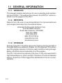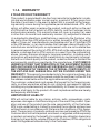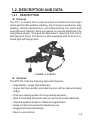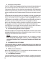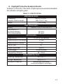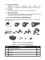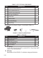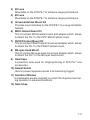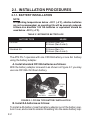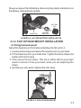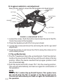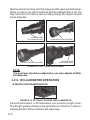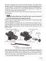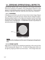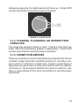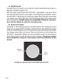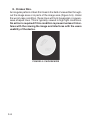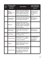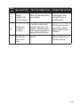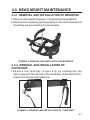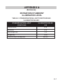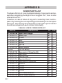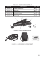
1
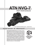
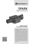
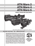
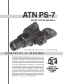
ATN PS-7 NIGHT VISION goggle PS-7 operator’s manual (Rev. 1, november 2010) operator’s manual Important Export Restrictions! Commodities, products, technologies and services contained in this manual are subject to one or more of the export control laws and regulations of the U.S. Government and they fall under the control jurisdiction of either the US Department of State or the US BIS-Department of Commerce. It is unlawful and strictly prohibited to export, or attempt to export or otherwise transfer or sell any hardware or technical data or furnish any service to any foreign person, whether abroad or in the United States, for which a license or written approval of the U.S. Government is required, without first obtaining the required license or written approval from the Department of the U.S. Government having jurisdiction. Diversion contrary to U.S. law is prohibited. Register your product warranty online at www.atncorp.com/warranty The information in this manual is furnished for information use only, is subject to change without notice, cannot be construed as a commitment by ATN Corp. ATN Corp. assumes no responsibility or liability for any errors or inaccuracies that may appear in this book. © 2010 ATN Corp. All right reserved. SAFETY SUMMARY STUDY CAREFULLY THIS MANUAL BEFORE TURNING ON AND OPERATING THIS PRODUCT. CAUTIONS PS-7 night vision units are precision optico-electronic instruments and requires careful handling. To provide safe use of the goggles the following instructions should be observed: •Do not dismantle the unit. •Keep the unit clean; protect it from moisture, sharp temperature drops and shocks. •Be careful not to touch the glass surfaces. If you put finger-prints on, or contaminate the glass surfaces, use only clean and soft materials to clean it. •Protect the unit from excessive lighting. Do not turn the goggles on in daylight with the front lens cap off. Do not point the goggles at the bright light source (a fire, car headlights, lanterns, street lamps, room lights, etc.). • Do not test the device in daylight conditions even with the daylight filter/lens cap on for more than ten (10) minutes. •Do not leave the unit in on position during stops in operation. •Remove the battery from the unit when storing for periods exceeding 3 days. Failure to do so may damage unit. Caution : This product contains natural rubber latex which may cause allergic reactions. a Equipment Limitations To avoid physical and equipment damage when using the ATN PS-7, carefully read and understand the following equipment limitations. • The equipment requires some night light (moonlight, starlight, etc.) to operate. The level of equipment performance depends upon the level of light. • Night light reduces by passing through the clouds, while operating under trees, at building shadows, etc. • The equipment is less effective when viewing into shadows and other darkened areas. • The equipment is less effective when viewing through the rain, fog, sleet, snow or smoke. • The equipment will not “see” through the dense smoke. •Has protection system, which cuts off the image intensifier when ambient light level exceeds the limit of 40 lux during a 10 seconds period. •Under starlight conditions low contrast environments (such as snowcovered territory, sandy deserts, large bodies of water or grassy hills) degrade visibility thereby disguising or masking changes in terrain. •Under too low-light conditions the goggles looses some of the resolution that it has under full moon. b TABLE OF CONTENTS pg. SAFETY SUMMARY a SECTION I. INTRODUCTION 1.1. General 1.1.1. Goggles 1.1.2.Reports 1.1.3. Storage 1.1.4. Warranty 1.2. Description and Data 1.2.1. Description 1.2.2.PS-7 Standard Components 1.2.3.PS-7 Optional Components 1-1 1-2 1-2 1-2 1-2 1-3 1-5 1-5 1-8 1-9 SECTION II. OPERATING INSTRUCTIONS 2.1. Installation Procedures 2.1.1. Battery Installation 2.1.2. Flip-Up Head Mount Installation 2.1.3. Helmet Mount Installation 2.1.4. 3x Lens Installation 2.1.5. 5x Lens Installation 2.1.6. 8x Lens Installation 2.1.7. IR-450 Installation 2.2.Operating Procedures 2.2.1. Controls and Indicators 2.2.2.Preparation for Operation 2.2.3. Operation in the Dark Condition 2.2.4.Focusing 2.2.5.IR Illuminator Operation 2.2.6. Shut-down Operation 2-1 2-2 2-2 2-3 2-5 2-6 2-6 2-7 2-8 2-9 2-9 2-10 2-11 2-11 2-12 2-14 SECTION III. OPERATIONAL DEFECTS 3.1. Zeroing Operational Defects 3.1.1. Shading 3.1.2.Edge Glow 3-1 3-2 3-2 3-3 i 3.1.3. Flashing, Flickering, or Intermittent Operation 3.1.4. Cosmetic Blemishes 3-3 3-3 SECTION IV. MAINTENANCE INSTRUCTIONS 4-1 4.1. Preventive Maintenance Checks and Services (PMcS) 4-2 4.1.1. Purpose of PMCS 4-2 4.1.2. Frequency of Performing PMCS 4-2 4.2. Troubleshooting Procedures 4-4 4.3. Maintenance Procedures 4-6 4.3.1. PS-7 Maintenance 4-6 4.3.2.Cleaning Procedures 4-7 4.4. Head Mount Maintenance 4-7 4.4.1. Removal and Installation of Browpad 4-7 4.4.2. Removal and Installation of Chinstrap 4-7 4.4.3. Removal and Installation of Chin Cup 4-8 4.4.4. Preparing for Extended Storage 4-8 Appendix A. Estimation of Ambient Illumination LevelA-1 Appendix B. Spare Parts List B-1 For Technical Information INFO-1 ii SECTION I introduction 1-1 1.1 General Information 1.1.1. Goggles This manual contains instructions for use in operating and maintaining the ATN PS-7. Throughout this manual, the ATN PS-7 will be referred to as the goggles or the PS-7. 1.1.2. Reports Reports from the user on recommendations for improvements are encouraged. Send reports to the address below. American Technologies Network Corp. 1341 San Mateo Avenue South San Francisco, CA 94080 (800) 910-2862 (650) 989-5100 (650) 875-0129 fax www.atncorp.com [email protected] 1.1.3. Storage Storage of the PS-7 should be done in the factory packing and after a thorough PMCS as outlined in Chapter IV of this manual. This will ensure the goggles remains in mission ready condition during storage. Battery should be stored separately from the goggles. The PS-7 should not be placed on the floor, in any area exposed to high temperatures or direct sunlight. Presence of acid and alkaline vapour, as well as of other aggressive admixtures in the air is unacceptable. 1-2 1.1.4.Warranty 2 Year Product Warranty This product is guaranteed to be free from manufacturing defects in material and workmanship under normal use for a period of 2 (two) years from the date of purchase. In the event a defect that is covered by the foregoing warranty occurs during the applicable period stated above, ATN, at its option, will either repair or replace the product, and such action on the part of ATN shall be the full extent of ATN’s liability, and the Customer’s sole and exclusive remedy. This warranty does not cover a product (a) used in other than its normal and customary manner; (b) subjected to misuse; (c) subjected to alterations, modifications or repairs by the Customer of by any party other than ATN without prior written consent of ATN; (d) special order or “close-out” merchandise or merchandise sold “as-is” by either ATN or the ATN dealer; or (e) merchandise that has been discontinued by the manufacturer and either parts or replacement units are not available due to reasons beyond the control of ATN. ATN shall not be responsible for any defects or damage that in ATN’s opinion is a result from the mishandling, abuse, misuse, improper storage or improper operation, including use in conjunction with equipment which is electrically or mechanically incompatible with or of inferior quality to the product, as well as failure to maintain the environmental conditions specified by the manufacturer. CUSTOMER IS HEREBY NOTIFIED THAT OPERATION OF THE EQUIPMENT DURING DAYLIGHT HOURS OR UNDER ANY EXCESSIVE LIGHT CONDITIONS MAY PERMANENTLY DAMAGE THE INTERNAL COMPONENTS OF THE UNIT AND SAID DAMAGE WILL NOT BE COVERED UNDER THIS WARRANTY. This warranty is extended only to the original purchaser. Any breach of this warranty shall be waived unless the customer notifies ATN at the address noted below within the applicable warranty period. The customer understands and agrees that except for the foregoing warranty, no other warranties written or oral, statutory, expressed or implied, including any implied warranty of merchantability or fitness for a particular purpose, shall apply to the product. All such implied warranties are hereby and expressly disclaimed. Limitation of Liability ATN will not be liable for any claims, actions, suits, proceedings, costs, expenses, damages or liabilities arising out of the use of this product. Operation and use of the product are the sole responsibility of the Customer. ATN’s sole undertaking is limited to providing the products and services outlined herein in accordance with the terms and conditions of this Agreement. The provision of products sold and services performed by ATN to the Customer shall not be interpreted, construed, or regarded, either expressly or implied, as being for the benefit of or creating any obligation toward any third party of legal entity outside ATN and the Customer; ATN’s obligations under this Agreement extend solely to the Customer. 1-3 ATN’s liability hereunder for damages, regardless of the form or action, shall not exceed the fees or other charges paid to ATN by the customer or customer’s dealer. ATN shall not, in any event, be liable for special, indirect, incidental, or consequential damages, including, but not limited to, lost income, lost revenue, or lost profit, whether such damages were foreseeable or not at the time of purchase, and whether or not such damages arise out of a breach of warranty, a breach of agreement, negligence, strict liability or any other theory of liability. Product Warranty Registration In order to validate the warranty on your product, ATN must receive a completed Product Warranty Registration Card for each unit or complete warranty registration on our website at www.atncorp.com. Please complete the included form and immediately mail it to our Service Center: ATN Corporation, 1341 San Mateo Avenue, South San Francisco, CA 94080. Obtaining Warranty Service To obtain warranty service on your unit, End-user must notify ATN service department by calling 800-910-2862 or 650-989-5100 or via e-mail [email protected] to receive a Return Merchandise Authorization number (RMA). When returning please take or send the product, postage paid, with a copy of your sales receipt to our service center, ATN Corporation at the address noted above. All merchandise must be fully insured with the correct postage; ATN will not be responsible for improper postage or, missing or damaged merchandise during shipment. When sending product back, please clearly mark the RMA# on the outside of the shipping box. Please include a letter that indicates your RMA#, Name, Return Address, reason for service return, Contact information such as valid telephone numbers and/or e-mail address and proof of purchases that will help us to establish the valid start date of the warranty. Product merchandise returns that do not have an RMA listed may be refused or a significant delay in processing may occur. Estimated Warranty service time is 10-20 business days. End-user/customer is responsible for postage to ATN for warranty service. ATN will cover return postage/shipping to continental USA end-users/customers after warranty repair only if product is covered by aforementioned warranty. ATN will return product after warranty service by domestic ground service and/ or domestic mail. Any other requested, required or international shipping method the postage/shipping fee will be the responsibility of the end-user/ customer. 1-4 1.2.Description and Data 1.2.1. Description A. Purpose The PS-7 is a hand-held, head mounted or helmet mounted night vision system that enables walking, short-range surveillance, map reading, vehicle maintenance, and administering first aid in both moonlight and starlight. Each unit allows for vertical adjustment (by using head straps), fore-and-aft adjustment, objective lens focus, and eyepiece focus. The device is also equipped with an built-in infrared light-emitting source. Figure 1-1. ATN PS-7 B. Features The ATN PS-7 has the following important features: • High Quality image intensifier tube • Super fast lens system provides the user with a clear and sharp image • Dual eye viewing system for long viewing sessions • Built-in Infra Red illuminator lets you see even in total darkness • Interchangeable lenses for different magnification • Head or helmet mounted for hands free use • Rugged and versatile design • Easy to use controls 1-5 C. Principle of Operation The PS-7 Night Vision goggles utilize the principle of intensification of the residual light which is reflected from the surrounding objects. The device consists of the objective lens assembly, two eyepieces and the body. The body contains a image intensifier tube assembly with an integrated high voltage power source and the battery housing. Objective lens protective cover is intended to protect the objective lens from dust and scratches. It also will act as a daylight filter, allowing you to test the scope in daylight or other bright light situations. The pinhole in the center of the protective cover allows the user to check the operation ability of the device in daylight conditions. Built-in IR Illuminator makes it possible to observe the objects when the goggles work in the conditions of low light or total darkness. The eyepiece incorporates red LED indicator serves as an IR Illuminator Indicator and an Battery Low Indicator at a time. D. Automatic Brightness Control System The device has a built in Automatic Brightness Control. Even under unsteady brightness conditions, this system always keeps the image intensifier tube brightness level constant. NOTE Automatic Brightness Control System do not protect a device from damage by bright light sources (a fire, headlights of the automobile, lanterns, etc.). Do not point the device at a bright light source. E. Automatic Shut-off System The Automatic Shut-Off System tracks when the unit is not used (the controls are not touched for 20 minutes continuous) and shuts the unit off automatically. F. IR Illuminator Indicator Built-in IR illuminator of PS-7 is on when the red LED indicator in fild of view of goggles light becomes stable. G.Low Battery Indicator If the red indicator in the FOV starts flickering, it means there might be about 20% of battery charge left. It is time to change your battery. 1-6 H. Highlight Protective System Indicator Indicator in the FOV. If the level of light exposure exceeds allowable the indicator will lights green. Table 1-1. Specification Mechanical Data: Dimensions (Length x Width x Height) 6.5” x 2.9” x 4.6” / 165 x 75 x 117 mm Weight 1.0 lb/0.48 kg Electrical Data: Battery One AA (1.5 V) or CR123A (3 V) Cell Life at 20 ˚C: AA Alkaline Battery 123A Lithium Battery 25 hours 50 hours Optical Data: Magnification 1X (3X, 5X, 8X optional) Objective Lens Focal Length 27 mm Objective Lens F/number 1:1.2 Field of View Diopter Adjustment Focus Range Interpupillary Distance 40° -6 to +2 0.25 m to infinity 58 - 72 mm Environmental Data: Operating Temperature -40 to +50 ˚C Storage Temperature -50 to +70 ˚C Illumination Required Natural night illumination (overcast starlight to moonlight) 1-7 1.2.2. PS-7 Standard Components The PS-7 standard components are shown in Figure 1-2 and presented in Table 1-2. 3 1 4 2 5 6 7 8 Figure 1-2. PS-7 Standard Components Table 1-2. PS-7 Standard Components DESCRIPTION ITEM QTY 1 ATN PS-7 1 2 Objective Lens Cap 1 3 Eye Cups 1 4 CR123A, Lithium Battery 1 5 Battery Adapter 1 6 Flip-up Goggle Kit 1 7 Soft Bag 1 8 Operating Manual 1 1) ATN PS-7 Goggles The PS-7 night vision device with 1x magnification. 2) Objective Lens Cap A cap used to protect the lens and for testing the unit in the daylight. 3) Eye Cups A rubber cups used to protect eyepiece and for operator comfort. 4) CR123A, Lithium Battery CR123A lithium batteries used to power the unit. 5) Battery Adapter Allows the PS-7 to accept the CR123A Lithium and AA size batteries used to power the unit. 1-8 6) Flip-up Goggle-Kit Adjustable universal assembly that secures the ATN PS-7 to the operator’s head providing hands-free operation. 7) Soft bag A protective bag used to store PS-7 and accessories. 8) Operating Manual Provides equipment description, use of operator controls and preventative maintenance checks and service. 1.2.3. PS-7 optional Components The PS-7 optional components are shown in Figure 1-3 and presented in Table 1-3. 1 2 3 4 5 6 9 10 7 11 8 12 Figure 1-3. PS-7 optional Components Table 1-3. PS-7 optional Components DESCRIPTION ITEM QTY 1 IR-450 IR illuminator kit 1 2 3X Lens 1 3 5X Lens 1 4 8X Lens 1 1-9 Table 1-3. PS-7 optional Components DESCRIPTION ITEM QTY 5 Universal Helmet Mount Kit 1 6 MICH Helmet Mount Kit 1 7 PAGST Helmet Mount Kit 1 8 Mil-spec Head Mount 1 9 Hard Case 1 10 Demist Shield 2 11 Sacrificial Window 1 12 Neck Strap 1 IR Illuminator Kit is shown in Figure 1-4 and listed in Table 1-4. 1 2 3 4 5 Figure 1-4. IR450 IR Illuminator Kit Table 1-4. IR450 Kit ITEM DESCRIPTION QTY 1 IR450-B4 Illuminator 1 2 Picatinny Rail 1 3 CR123A type battery 1 4 1.5 mm Allen Key 1 5 IR450 Wrench 1 1) IR-450 Kit A 450 mW infrared illuminator is powerfull for long range night vision in the total darkness. 2) 3X Lens Mountable on the ATN PS-7 to enhance range performance. 1-10 3) 5X Lens Mountable on the ATN PS-7 to enhance range performance. 4) 8X Lens Mountable on the ATN PS-7 to enhance range performance. 5) Universal Helmet Mount Kit Provides mount interface for the ATN PS-7 to a range of ballistic helmets. 6) MICH Helmet Mount Kit This kit contain MICH helmet mount and adapter which allows to attach the PS-7 to the PVS7 MICH helmet mount. 7) PAGST Helmet Mount Kit This kit contain PAGST helmet mount and adapter which allows to attach the PS-7 to the PAGST helmet mount. 8) Mil-spec Head Mount This kit contain Mil-spec head mount and adapter which allows to attach the PS-7 to the Mil-spec head mount. 9) Hard Case A protective case used for shipping/storing of ATN PS-7 and accessories. 10)Demist Shield Used to prevent eyepiece lenses from becoming fogged. 11) Sacrificial Window A replaceable window supplied to protect the objective lens during operation in adverse conditions. 12)Neck Strap 1-11 1-12 SECTION II operating instructions 2-1 2.1.Installation Procedures 2.1.1. Battery Installation NOTE At operating temperatures below –20°C (–4°F), alkaline batteries are not recommended, as operating life will be severely reduced. Lithium-iron disulfide 1.5V AA batteries or equivalent should be used below –20°C (–4°F). Table 2-1 Estimated Battery Life BATTERY TYPE USAGE CR123A 60 Hours (Gen. 2+) 50 Hours (Gen.3 and 4) Standard AA 30 Hours(Gen. 2+) 25 Hours (Gen.3 and 4) The ATN PS-7 operates with one CR123A battery or one AA battery using the battery adapter. A. Install standard CR123A batteries as follows: With the battery adapter screwed in as shown on Figure 2-1 you may use one CR123A 3V lithium battery. battery cap CR123 battery battery adapter Figure 2-1. CR123A type battery installation B. Install AA batteries as follows: To install a AA battery, take the battery adapter out of the battery cap, turn it over, and screw its smaller threading into the same battery cap. 2-2 Now you may put the AA battery observing the polarity indications on the battery compartment surface. battery cap AA battery battery adapter Figure 2-2. AA type battery installation 2.1.2. flipup head mount Installation A. Fitting the head mount Adjust the head mount first before attaching the NV unit to it. 1. Loosen all the straps and place the head mount on your head. 2. Fit the head mount to your head size. Tighten the back straps and fixate it with Velcro tape. 3. Then secure the top straps. This one is rather tight so you might need to remove it from your head, when you are adjusting the straps. 4. And last you will need to tighten the chin strap. Figure 2-3. flipup head mount 2-3 B. Goggles installation and adjustment Now you are ready to mount the NV goggles onto head mount. button B top straps button A screw back straps socket bracket button C chin strap Figure 2-4. head mount of PS-7 1. Loosen the screw. Push the button A and insert the rail of the PS15 into the socket of the headset. 2. Place the headmount with PS-15 on your a head. 3. Loosen the screw and move the unit along the rail for eye relief adjustment. 4. Push the button C and move the PS-15 along the slide rail for comfortable position. c. Flip-up Mechanism 1. The PS-7 headmount has a flip-up mechanism. Push the side button B on the mount and lift the unit up until the unit stops in the top position. When the device reaches the top/upper position it will turn off automatically. 2.Push the same button B to lower PS-7 into the viewing position. The unit will automatically turn back on again for continuation of the operation. 2-4 NOTE Some of PS-7 contain Flip-up Shutoff System. This system turns the unit off when the PS-7 is upright on the flip-up head mount. The unit will automatically turn back on again for continuation of the operation. 2.1.3. helmet mount Installation Helmet mount for attachment of ATN’s PS-7 to a standard PASGT helmet. Helmet mount fits securely onto helmet via a rugged strapping device and grooved hooks. With helmet mount, PS-7 can be positioned directly in front of user’s eyes or flipped. A. Installation 1. Install the mount onto the helmet as shown on the picture. 2. Tighten and fix the straps. 3. Attach the goggles to the rail. 4. Loosen screw. Push button B and insert the bracket of the PS-7 into socket of the helmet mount. 5. Place the helmet with PS-15 onto head. FIXATION LEVER KNOB straps button a button C button B screw socket bracket straps Figure 2-5. helmet mount Installation and adjustment B. Adjustment 1. Loosen the screw and move the unit for proper eye relief adjustment. 2. Turn the fixation lever down and move the unit along the rail for vertical position adjustment. Turn the lever up and tighten it for fixation of vertical position. 3. Push the button C and move the PS-7 along the slide rail for comfortable position. 4. The PS-7 helmet mount has a flip-up mechanism. Push the button A on the side of mount and lift the unit up until the unit gets fixed in 2-5 the top position. When the device reaches the top/upper position it will turn off automatically. 5. Push the same button A to lower PS-15 to viewing position. The unit will automatically turn back on again for continuation of the operation. 6. The mounting mechanism of helmet mount can be detached from headgear. Pull the knob and move the mounting mechanism down along the rail. 2.1.4. 3X lens Installation To install 3X Afocal Lens screw it into the thread of front lens of PS-7. Figure 2-6. PS-7 with 3X lens and IR450 2.1.5. 5X lens Installation To install 5X lens unscrew the standard objective lens of PS-7 from the body. To install lenses screw 5X lens to the free place (make sure that the unit is turned off). Figure 2-7. PS-7 with 5X lens 2-6 2.1.6. 8X lens Installation To install 8X lens unscrew the standard objective lens of PS-7 from the body. It is very important not to grasp the eyepieces but grasp the neck of unit. To install lenses screw 8X lens to the free place (make sure that the unit is turned off). ring socket fixing screws Figure 2-8. PS-7 with 8X lens Figure 2-9. PS-7 with 8X lens on the tripod PS-7 with 8X lens has a capability to be used with a tripod. 1.Loose two fixing screws of the ring. 2.Turn the ring until the socket is directed straight down. 2-7 3.Tighten the fixing screws. 4.Screw the tripod screw in to the tripod socket. NOTE Severe damage to the unit can occur if the tripod collapses or is knocked over. It is recommended that the PS-7 be removed if the user is not within arm’s reach of the tripod. 2.1.7. IR-450 installation IR-450 may be mounted on the monocular through the Picatinny adapter. 1. Mount Picatinny adapter onto the rail on the PS-7. Tighten two fixing screws of the adapter. 2. Loosen the IR-450 fixing nut. 3. Mount the IR-450 on the Picatinny adapter and tighten the fixing nut. Picatinny adapter screws fixing screw IR450 Figure 2-10. IR450 installation 2-8 2.2.Operating Procedures 2.2.1. Controls and indicators The PS-7 is designed to adjust for different users and corrects for most differences. The controls of the goggles are shown on Figure 2-11. The functions of controls and indicators are described in the Table 2-2. head mount Sensor of Highlight Protective System focus adjustment 1X lens Lens protective cover Battery Housing pivot plate Built-in infra-red illuminator Single switch knob operation Mounting bracket Diopter Adjustment Rings Eye Cups Battery Housing Cap Figure 2-11. PS-7 Controls and Main Elements 2-9 Table 2-2. PS-7 Controls and Indicators CONTROLS FUNCTION Focuses eyepiece lens without the need for glasses. Diopter Adjustment Adjusts for sharper image of intensifier screen. Focus Adjustment Focuses objective lens. Adjusts for sharpest image of viewed object. Single Switch Knob Operation Controls Unit power and built-in IR Illuminator. Rotate the operation knob from “OFF” position to “ON” position to turn the unit on. To turn the unit off, rotate the operation knob from “ON” to “OFF” position. To turn the built-in IR on, draw and rotate the operation knob to “IR” position. To turn the built-in IR off, draw and rotate the operation knob from “IR” position. Pivot Plate Focuses IR light for additional distance by placing the lens of the pivot plate onto window of IR illuminator. Shuts down the sensor of highlight protection system by placing the cap of the pivot plate onto window of sensor. Sensor of Highlight The automatic Highlight Protective System analyses Protective System light exposure with the sensor. Indicator in FOV When built-in IR illuminator is ON, the indicator in the FOV will lights red. When the battery is low the red indicator in the FOV starts blinking. 2.2.2.preparation for Operation For checking the device in daytime conditions or in a light room: 1. Make sure the battery is installed as indicated on the PS-7 body. 2. Make sure the lens cap is attached to the front lens. 3. Turn on the device by turning the operation knob to ON position. After this you can start observing scene through the oculars. The greenish-lit screen of the image tube means that the device is working normally. 4. Direct the PS-7 at an object located 15-25 yards/m from you and obtain a sharp image by turning eyepieces (see section 2.2.3). 2-10 5. Turn off the device by turning the operation knob to OFF position. CAUTION Never use your night vision device in daylight areas without the lens cover on! Never direct the lens to the bright light! 2.2.3. Operations in the dark conditions CAUTION Bright sources such as light of fire, headlights, searchlights, etc. can damage the PS-7. Avoid exposing the PS-7 to these types light sources. For start the operations in dark conditions: 1. Make visual estimation of the illumination level in the viewing area is less than 1 lux (late twilight sky conditions). 2. Remove the front lens cap and place it over the lens housing. 4. Turn on the device. A green glow will appear in the eyepiece (after a slight delay). 5. Observe the scene and adjust focus. 2.2.4.focusing To focus the PS-7, first you will need to adjust the diopter. Simply turn the diopter clockwise until it stops. Then, while looking through the diopter at an object, slowly turn the diopter back counter clockwise until the grain in the image is sharp. Figure 2-12. PS-7 diopter adjustment NOTE We suggest that you focus the diopter during daylight with the filter on. 2-11 Next focus the front lens until the image and the grain are both sharp. When you are in low-light conditions and the daylight filter is off, you may focus the front lens to receive sharp image, the diopter should not be adjusted. standard Lens focus adjustment 3x Lens focus adjustment 5x Lens focus adjustment 8X Lens focus adjustment ring Figure 2-13. PS-7 lens adjustment NOTE The front lens should be readjusted as you view objects at different distances. 2.2.5.ir illuminator operation A. Built-in Infra-Red Illuminator Figure 2-14. PS-7 Built-in Infra-Red Illuminator Infra-red illuminators, or IR illuminators, are common to night vision. The IR light greatly enhances the performance of the PS-7 while remaining almost totally invisible to the naked eye. 2-12 The PS-7 goggles have a built in IR with indicator “ON” light within the FOV. To turn the built-in IR on, draw and rotate the operation knob to “IR” position. It is important to remember that the IR illuminator is simply an infra red light source, and like any light source, it may loose its effectiveness over a great distance. To turn the built-in IR off, draw and rotate the operation knob from “IR” position. NOTE The IR will automatically turn off when the unit’s power is turned off. B. IR 450 Detachable Infra-Red Illuminator IR450 is powerful detachable infrared illuminator for long range night vision in the total darkness. The ATN IR450 is powered with one CR123A lithium battery. To install the battery unscrew the cap of the battery housing and insert the battery following the polarity arrows marked on the housing. Put the cap in place. IR BRIGHTNESS ADJUSTMENT POWER LED INDICATOR IR ELEVATION ADJUSTMENT NUT BATTERY HOUSING CAP IR FOCUSING FIXING NUT IR WINDAGE ADJUSTMENT ALLEN KEY BATTERY HOUSING WRENCH Figure 2-15. IR450 Illuminator The IR-450 illuminator has a control panel with two buttons. To switch the IR illuminator on/off press “+” and “-” buttons simultaneously. When the IR illuminator is switched on you can see the green LED lit on the back side of IR450. By pushing the buttons “+” and “-” you may adjust the IR brightness. 2-13 The IR beam is focusable to change the field of coverage. To change the beam width slightly turn the IR lens. You may need adjust the focusing of the IR beam to change the field of coverage. Do it by slightly rotating the IR lens. The windage and elevation screws help adjust the direction of the IR beam from the IR450 in order to focus on the scene observed in the viewfinder of your Wrench NVD. Use the included Allen wrench To Loosen Nut to rotate the adjusting screws until the IR beam is centered. Please remember the adjustments should be Control Panel performed under night light condiTo Tighten Nut tions only. You can change the position of the Nut IR control panel to meet your your needs. The wrench that is included in the set, is used to loosen the nut located on the body of the IR. Rotate the IR to the desired position. TightFigure 2-16. CHANGING OF en the nut with the wrench to secure CONTROL PANEL POSITION the new position. 2.2.6. Shut-down operations 1. Shot press button to turn the PS-7 off. The green of the image intensifier tube glow will fade to black. 2. Replace the protective cap on the front lens. 2-14 SECTION III OPERATIONAL DEFECTS 3-1 3.1. ZEROING OPERATIONAL DEFECTS Operational defects refer to the reliability of the image intensifiers and are an evidence of instability. Their identification shall be a valid reason to immediately refuse to accept the ATN PS-7. These include shading, edge glow, flashing, flickering, and intermittent operation. 3.1.1. Shading If shading is persistent, you will not see a fully circular image (Figure 3-1). Shading is very dark and you cannot see an image through it. Shading always begins on the edge and migrates inward eventually across the entire image area. Shading is a high contrast area with a distinct line of demarcation. Contact ATN or point of purchase for warranty/repair procedures. SHADING Figure 3-1. Shading NOTE Make sure the shading is not the result of improper exit pupil position. 3.1.2. Edge Glow Edge glow is a bright area (sometimes sparkling) in the outer portion of the viewing area (Figure 3-2). To check for edge glow, block out all light by cupping a hand over the lenses. If the image tubes are 3-2 displaying edge glow the bright area will still show up. Contact ATN or point of purchase for warranty/repair procedures. EDGE GLOW Figure 3-2. Edge Glow 3.1.3. Flashing, Flickering, or Intermittent Operation The image may appear to flicker or flash. If there is more than one flicker, check for loose battery adapter or weak battery. Contact ATN or point of purchase for warranty/repair procedures. 3.1.4. Cosmetic Blemishes These are usually the result of manufacturing imperfections that do not affect image intensifiers reliability and are not normally a reason to claim for warranty or repair work. However, some types of blemishes can get worse over time and interfere with the usability of the device. If you believe a blemish is a cause for rejection, warranty or repair please ATN or point of purchase for warranty/repair procedures. 3-3 A. Bright Spots. A bright spot is a small, non-uniform, bright area that may flicker or appear constant (Figure 3-3). Not all bright spots make the ATN PS-7 rejectable. Cup your hand over the lenses to block out all light. If the bright spot remains, return the ATN PS-7. Bright spots usually go away when the light is blocked out. Make sure any bright spot is not simply a bright area in the scene you are viewing. Bright spots are acceptable if they do not interfere with the ability to view the outside scene. B. Emission Points. A steady or fluctuating pinpoint of bright light in the image area and does not go away when all light is blocked from the objective lenses of the bi-ocular (Figure 3-3). The position of an emission point within the image area does not move. Not all emission points make the ATN PS-7 rejectable. Make sure any emission point is not simply a point light source in the scene you are viewing. Emission points are acceptable if they do not interfere with the usability of the device. EMISSION POINT BRIGHT SPOT Figure 3-3. Bright Spots and Emission Points 3-4 C. Black Spots. These are cosmetic blemishes in the image intensifiers or dirt or debris between the lenses. Black spots are acceptable as long as they do not interfere with viewing the image. No action is required if this condition is present unless the spots interfere with the usability of the device. D. Fixed-Pattern Noise. This is usually a cosmetic blemish characterized by a faint hexagonal (honeycomb) pattern throughout the viewing area that most often occurs at high light levels or when viewing very bright lights (Figure 3-4). This pattern can be seen in every image intensifier if the light level is high enough. This condition is acceptable as long as the pattern does not interfere with viewing the image and usability of the device. Figure 3-4. Fixed-Pattern Noise 3-5 E. Chicken Wire. An irregular pattern of dark thin lines in the field of view either throughout the image area or in parts of the image area (Figure 5-5). Under the worst-case condition, these lines will form hexagonal or squarewave shaped lines. This is typically viewed in high light conditions. No action is required if this condition is present unless it interferes with the viewing the image and interferes with the users usability of the device. Figure 3-5. Chicken Wire 3-6 SECTION IV maintenance instructions 4-1 4.1. Preventive Maintenance Checks and Services (PMCS) 4.1.1. Purpose of PMCS PMCS is performed daily when in use to be sure that the PS-7 is ready at all times. Procedures listed in Table 4-1 are a systematic inspection of the PS-7 that will enable you to discover defects that might cause the sight to fail on a mission. 4.1.2. Frequency of performing PMCS The frequency of performing PMCS is as follows: 1.Daily when the PS-7 is in use. 2.When it is removed from the case for any reason. Table 4.1 Preventive Maintenance Checks and Services for PS-7 SEQ. NO. 1 LOCATION ITEM TO CHECK/ SERVICE Maintenance PROCEDURE NOT FUNCTIONING AT OPTIMAL LEVEL IF Open carrying case, inventory Not Current. items. Previously recorded faults on Fault not cormaintenance records. rected. goggles 2 Optical Surfaces Inspect lenses for dirt, fingerprint residue, chips, or cracks. If necessary, clean and dry lens with water and lens tissue. Scratches or chips hinder vision with goggles turned on, or if cracks are present. 3 External Surfaces Inspect for cracks or damage. Scratches and gouges are OK if operation is not affected Cracked or damaged. 4-2 SEQ. NO. LOCATION ITEM TO CHECK/ SERVICE PROCEDURE NOT FUNCTIONING AT OPTIMAL LEVEL IF 4 Check to make sure battery adapter is present. Remove Battery Adapter / Com- battery adapter and inspect for corrosion, moisture, corpartment roded or defective contacts. 5. Rotate diopter adjustment ring Binding, not Diopter Adjustmoving freely or to make sure the eyepiece is ment Rings too loose. not too tight or too loose. 6 Eyecups 7 Rotate objective lense focus Objective Lens rings to ensure free moveFocus Ring ment. 8 Lens Cap Inspect for cracked, torn, or missing lens cap. 9 Viewed Image Refer to Section V – Operation Defects – to inspect for operational defects. Bracket Inspect for dirt, dust, or corrosion. If necessary, clean socket with water. Carrying Case Remove all items and shake out loose dirt or foreign material. Inspect for tears, cuts, excess wear or damage to mounting clips. 10 11 Adapter is missing, contacts damaged or corroded. Inspect for dirt, dust, and cracked or torn cups. Inspect for bent, broken or improperly fitting eyecups. If necessary, clean with water. Binding or not moving freely. Flickering, flashing, edge glow, or shading is observed. 4-3 4.2. TROUBLESHOOTING Procedures Table 4.2. lists common malfunctions that you may find in your equipment. Perform the tests, inspections, and corrective actions in the order they appear in the table. This table cannot list all the malfunctions that may occur, all the tests and inspections needed to find the fault, or all the corrective actions needed to correct the fault. If the equipment malfunction is not listed or actions listed do not correct the fault, notify ATN or your point of Purchase. Table 4.2 Troubleshooting Procedures for PS-7 SEQ. MALFUNCTION NO. 1 2 3 4 4-4 Goggles fail to activate. TEST OR INSPECTION Turn on the device. Check for defective, missing or improperly installed batteries. CORRECTIVE ACTION Turn on the device again. Replace the battery or install it in a proper way. Refocus. Poor image quality Check objective lenses or eyepieces focus. Check for fogging or dirt on lenses. Light visible around eyecups Check eye-relief distance. Check eyecups for resiliency. Readjust for proper eye-relief distance. If eyecups are defective, refer to higher level of maintenance. Diopter adjustment cannot be made Check to see if the diopter adjustment rings are bent or broken If damaged, refer to higher level of maintenance. Clean lenses surface. If image quality is still poor, refer to higher level of maintenance. SEQ. MALFUNCTION NO. 5 Battery adapter difficult to remove. 6 IR illuminator fails to activate. 7 IR indicator fails to activate. TEST OR INSPECTION Check for damaged battery adapter. In a dark location with system turned on, activate IR. Visually check IR illuminator operation; scene should brighten. Visual. CORRECTIVE ACTION If damaged, refer to higher level of maintenance. If IR illuminator fails to activate, refer to higher level of maintenance. Refer to higher level of maintenance. 4-5 4.3.Maintenance Procedures 4.3.1. PS-7 Maintenance The PS-7 maintenance consists of external inspection of its components for serviceability, cleaning and installation of the standard and optional accessories. Maintenance instructions covered elsewhere in this manual (PMCS, troubleshooting, etc.) are not repeated in this section. CAUTION The PS-7 is a precision electron-optical instrument and must be handled carefully at all times to prevent damage. 4.3.2. Cleaning Procedures 1.Gently brush off any dirt from the goggles body using only a clean soft cloth. 2.Moisten the cloth with fresh water and gently wipe the external surfaces (except lenses). 3.Dry any wet surfaces (except lenses) with another dry and clean soft cloth. 4.Using lens brush, carefully remove all loose dirt from the lenses. 5.Slightly dampen a cotton swab with ethanol and lightly and slowly wipe the lenses. Clean the glass surfaces by circular movements from the centre to the edge, not touching the lens holder and changing cotton swab after each circular stroke. Repeat this step until the glass surfaces are clean. CAUTION Dry thoroughly each item before replacing into the storage case. 4-6 4.4. HEAD MOUNT MAINTENANCE 4.4.1. Removal and Installation of Browpad 1.Remove old browpad (Figure 6-1) by grasping the headband. 2.Replace the browpad by gently pressing on the new browpad and smoothing out any wrinkles in new browpad. Figure 6-1. Removal and Installation of Browpad 4.4.2. Removal and Installation of Chinstrap 1.Remove the c hinstrap ( Figure 6 -2) by unsnapping the Velcro tape from the left side of the headband. Unbuckle the chinstraps from narrow strap assembly. Figure 6-2. Removal and Installation of Chinstrap 4-7 2.Replace the chinstrap by using the Velcro tape on the left side of the headband. Lace the right straps into their respective sliding bar buckles on the right side of the headband for correct lacing (Figure 6-2). 4.4.3. Removal and Installation of Chin Cup 1.Remove the chinstrap ( Figure 6 - 3 ) by unsnapping the Velcro tape from the left side of the headband. 2.Replace the chin cup by sliding the cap on the chinstrap. Fix the Velcro tape onto the place. Figure 6-3. Removal and Installation of Chin Cup 4.4.4. Preparing for Extended Storage To prepare the PS-7 for extended storage, perform the following: 1.Check the goggles for serviceability as outlined in item 4.1 of this manual. 2.Remove the batteries. 3.Clean the goggles and accessories. 4.Replace all items in the case. 4-8 APPENDIX A (Reference) ESTIMATION OF AMBIENT ILLUMINATION LEVEL Table A-1. Standard Natural Light Conditions and Illumination Values STANDARD NATURAL LIGHT CONDITIONS ILLUMINATION VALUE, LUX Quarter moon 0.05 Full moon 0.30 Late twilight sky 1.00 Twilight sky 10.00 Overcast sky in the daytime 500.00 A-1 APPENDIX B spare PARTS LIST The Spare Parts List is an illustrated catalog of main parts and assemblies completing the Night Vision Goggles PS-7, here in after referred to as PS-7. Therefore, in case of failure of any part or assembly User could replace it by ordering the corresponding part/assembly from the Spare Parts List. The amount and assortment of the spare parts needed should be arranged with each contract individually. Table B-1. ATN PS-7 spare parts list PART NO. DESCRIPTION FIG. ITEM AT 201500.700 Night Vision Goggle B1 AT 201500.701 Battery Cap B1 1 AT 201500.702 1x Lens B1 2 AT 201500.703 Body B1 3 AT 201500.704 Bracket B1 4 AT 201500.705 Eye Cup B1 5 AT 201500.706 Battery Adapter B1 6 CR123A CR123A Battery B1 7 AT 201501.700 Accessories 1 (From the Kit) B2 AT 201501.701 Head Mount B2 1 AT 201501.702 Carrying Case B2 2 AT 201501.703 Operators Manual B2 3 AT 201502.700 Accessories 2 (Optional) B3 AT 201502.701 IR450 Kit B3 1 AT 201502.702 3X Lens B3 2 AT 201502.703 5X Lens B3 3 AT 201502.704 8X Lens B3 4 AT 201502.705 MICH Helmet Mount Kit B3 5 AT 201502.706 PAGST Helmet Mount Kit B3 6 B-2 B-1 Table B-1. ATN PS-7 spare parts list PART NO. DESCRIPTION FIG. ITEM AT 201502.707 Mil-spec Head Mount B3 7 AT 201502.708 Hard Case B3 8 AT 201502.709 Demist Shield B3 9 AT 201502.710 Sacrificial Window B3 10 AT 201502.711 Neck Strap B3 11 4 1 2 5 6 7 3 Figure B-1. NIGHT VISION GOGGLES 1 2 3 Figure B-2. aCCESSORIES 1 (FROM THE KIT) B-2 B-1 1 3 2 7 6 5 8 4 9 10 11 Figure B-3. aCCESSORIES 2 (optional) B-3 B-2 12 For Technical Information ATN Corp. 1341 San Mateo Avenue South San Francisco, CA 94080 (800) 910-2862 (650) 989-5100 tel. (650) 875-0129 fax 26042012 www.atncorp.com [email protected] INFO-1 For customer service and technical support, please contact American Technologies Network Corp. North American Office 1341 San Mateo Avenue, South San Francisco, CA 94080 phone: 800-910-2862, 650-989-5100; fax: 650-875-0129 European Office The following countries can use our toll free number: 00 800 9102-8620 Austria, France, Germany, Holland, Italy, Spain, Sweden, Switzerland For other countries, please use 38 048-7770214 or 38 048-7770345 www.atncorp.com ©2010 ATN Corporation