1
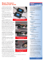
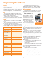
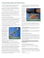
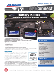
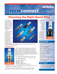
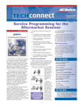
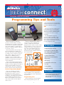
March/April 2009 Volume 16, No. 2 (TS-PU-0007-09)
Programming Tips and Tools
enable J2534 pass-through programming and can work on Controller Area
Network (CAN) data vehicles.
GM
The Tech 2 scan tool can be used
for programming of non-CAN data
vehicles. A Controller Area Network
diagnostic interface (CANdi) module
is needed for the Tech 2 to read
CAN data.
When to program or reflash an
electronic control module is usually
dictated by three conditions: directed by
a technical service bulletin, installing a
new control module, or a VIN search
identifies a calibration update related to
a customer concern.
Performing a VIN search through the
vehicle manufacturer’s website can
save time and money when diagnosing
a condition. No one wants to unnecessarily replace a part only to find out
that there is a calibration that is
needed to fix the condition. Many
calibration releases from vehicle manufacturers no longer have associated
technical bulletins.
Since control module programming
has become prevalent during repairs of
all types, whether replacing a module or
fixing a related condition, there are
many things to take into consideration
before, during and after programming.
Service Programming Symbol
There are a number of control
modules that are capable of being
programmed or require a service
setup after service programming or
installation, everything from the Engine
Control Module and the Electronic
Brake Control Module to the heated
seat control module and the digital
radio receiver.
A Service Programming symbol is
used in the Service Information to
indicate components that may be
programmed or require a service setup
after installation or service. Click on the
symbol in the Service Information to
go to the Control Module Reference
table. The table lists the appropriate
programming and setup procedure for
the control module.
The GM Multiple Diagnostic
Interface (MDI) is available for programming CAN data vehicles and
offers faster programming than the
Tech 2 while freeing up the scan tool
for other diagnostic work.
continued on page 3
IN THIS ISSUE
Programming Tips and Tools . . . . . . . .1
Buyer Beware: Counterfeit Tools . . . .2
New ACDelco Advanced Cooling
System Diagnosis Seminar . . . . . . . . .4
Checking Coolant Hoses . . . . . . . . . . .4
2009 TSS Scholarship Deadline
Approaching . . . . . . . . . . . . . . . . . . . . . .5
ASE Testing . . . . . . . . . . . . . . . . . . . . . . .5
Controlling Diesel Emissions . . . . . . . .6
Tech Tips . . . . . . . . . . . . . . . . . . . . . . . . .7
The Service Programming symbol
indicates a module is capable of
programming or may need a service setup.
The Service Programming symbol
may also appear on the parts label of
some components or be embossed on
the part itself.
Programming Tools
Every manufacturer has developed
their own programming tools that
1
Training Update . . . . . . . . . . . . . . . . . . .8
Show Off Your Ride . . . . . . . . . . . . . . . .8
ON THE WEB
– www.acdelcotechconnect.com, click on
the TechConnect Magazine link, or
– Log on to the ACDelco LMS, click on the
Resources link
Buyer Beware:
Counterfeit Tools
Whatever you want, chances
are you can find it on the web.
But one of the chances you take
when buying items through an
online sale or an auction website
is if they’re the real thing
or fakes.
ACDelco TechConnect is published bi-monthly
and online for technicians of Total Service
Support (TSS) and Key Fleet accounts to
provide timely service information, increase
knowledge and improve the performance of
the service center.
Publisher:
Mike DeSander
ACDelco
E-mail /
[email protected]
GM and Bosch Diagnostics
have discovered counterfeit Tech
2 scan tools and GM Controller
Area Network diagnostic interface (CANdi) modules available
to the aftermarket through online
auction websites and other retail
websites.
Editor:
Can you tell the difference?
These tools appear to be very
The top CANdi module is counterfeit.
authentic from their exterior
appearance. Everything is copied
to closely resemble the real thing – from
the cables and plastic cases to the brand
logos and serial numbers. However,
some of these counterfeit tools acquired
by GM and Bosch Diagnostics have been
found to be built with lower grade components and electronics or with used
equipment from other diagnostic tools.
As a result, some of the counterfeit tools
will not work right from the start, may
fail quickly or will run extremely slow.
Technical Editors:
Mark Spencer
E-mail /
[email protected]
Jim Horner
E-mail /
[email protected]
Production Manager:
Marie Meredith
Desktop Publishing:
5by5 Design
E-mail /
[email protected]
In some cases, there are some
slight physical clues that identify a
counterfeit tool. Some fake CANdi
modules have the same serial number
on each module. Real CANdi modules
will have a different serial module
on each one.
The LED on the top of a counterfeit
CANdi module may be green. Real
CANdi modules have a clear LED that
glows green.
Mike Militello
ACDelco
E-mail /
[email protected]
Write to: *
An authentic CANdi module has
a clear LED that glows green (A),
not a green LED (B).
Another clue on counterfeit modules
may be the lack of a printed identifier
number on the cable. Plus, the cable
connectors of some counterfeit
modules have brass inserts. The real
modules use aluminum inserts.
Scan tools and diagnostic tools such
as the Tech 2 and CANdi module are
large investments for many service
centers. For buyers to ensure that they
are getting the real tool, and the tech
An authentic CANdi module uses
support and warranty protection (authenaluminum inserts on the cable (A),
not brass (B).
tic Tech 2 scan tools and CANdi modules
include a two-year warranty) that comes
with it, purchases should be made from a well known source
such as Bosch Diagnostics or OTC Tools.
The bottom line may be that if the online deal for diagnostic and scan tools
seems too good to be true, it probably is.
– Thanks to Bob Stewart and Mike Waszczenko
2
ACDelco TechConnect
P.O. Box 500
Troy, MI 48007-0500
:
On the Web:
To read and search recent issues of
TechConnect online:
– www.acdelcotechconnect.com,
click on the TechConnect Magazine
link, or
– Log on to the ACDelco LMS, click
on the Resources link
ACDelco service tips are intended for use by
professional technicians, not a “do-it-yourselfer.”
They are written to inform those technicians of conditions that may occur on some vehicles, or to provide information that could assist in the proper service of a vehicle. Properly trained technicians have
the equipment, tools, safety instructions and knowhow to do a job properly and safely. If a condition is
described, it cannot be assumed that the information applies to all vehicles or that all vehicles will
have that condition.
All materials and programs described in this
magazine are subject to change. Submission of
materials implies the right to edit and publish.
Inclusion in the publication is not necessarily an
endorsement of the individual or the company.
TechConnect is published for ACDelco by Sandy
Corporation, Troy, MI.
©2009 ACDelco. All rights reserved.
Programming Tips and Tools continued from page 1
Chrysler
The DRBIII supports vehicle programming but does not
work on CAN data vehicles.
The StarSCAN works on Chrysler’s CAN data vehicles. The
StarMOBILE adds wireless support, a custom data recorder,
and pass-through diagnostics, freeing up the StarSCAN for
more extensive diagnostic tasks.
Ford
The New Generation Star (NGS) Tester combined with
the NGS Web Flash Kit provides the ability to download Ford
calibration files and reprogram modules.
Integrated Diagnostic Software and the Vehicle
Communication Module are used to interface with standard
computer platforms (PCs, laptops) on CAN data vehicles.
Toyota
The Mastertech scan tool can be used on non-CAN data
vehicles.
The TIS techstream offers full support and reprogramming
for current CAN data Toyota/Scion/Lexus vehicles.
For more information about scan tools and other programming tools available from vehicle manufacturers, refer to the
following websites.
Reputable aftermarket tool manufacturers, such as
EASE Diagnostics, Snap-On Tools, SPX/OTC, and Bosch/
Vetronix, also offer various scan tools and pass-through
programming tools.
Proper Programming
Before programming a control module, there are several
important practices to follow to ensure that successful
programming occurs.
Vehicle system voltage – The
vehicle’s battery voltage should be
greater than 12 volts but less than
16 volts. The battery should be
charged before a programming
event. A battery charger should
NOT be connected to the battery
during programming unless it is a
Midtronics PSC charger validated
for use during programming.
Also turn off or disable any system or accessories that may put a
load on the battery, such as engine
cooling fans, the radio, Daytime
Running Lamps, etc.
Maintain battery voltage
during programming.
Ignition switch – The ignition switch must be in the On
position. Do not begin programming right away. It’s critical to
wait until all modules on the vehicle have “awakened” before
beginning. A good rule of thumb is to not plug in any tools
until the instrument panel lights and tones stop after the
initial key-on.
Audi
www.equipmentsolutions.com
BMW
www.centrallettershop.com
Chrysler
(Chrysler/Dodge/Jeep)
www.techauthority.com
Ford
(Ford/Lincoln/Mercury)
www.motorcraft.com
GM
(Buick/Cadillac/Chevrolet/
GMC/HUMMER/
Oldsmobile/Saturn)
www.acdelcotechconnect.com
Honda
(Honda/Acura)
www.serviceexpress.honda.com
Hyundai
www.dealerequipment.com
Kia
www.kiatechinfo.com
Mazda
www.mazdatechinfo.com
Mercedes-Benz
www.startekinfo.com
Mitsubishi
www.mitsubishitechinfo.com
Nissan
(Nissan/Infiniti)
www.nissantechinfo.com
Porsche
www.techinfo.porsche.com
• High-speed Internet access in the shop
Saab
www.saabtechinfo.com
• A high-quality J2534 pass-through tool
Subaru
www.techinfo.subaru.com
• A subscription to the manufacturer’s website
Toyota
(Toyota/Lexus/Scion)
www.techinfo.toyota.com
• Carefully reading all directions before and during the
downloading of the flash files or programming of the
control module
Volkswagen
erwin.volkswagen.com
Volvo
www.volvotechinfo.com
Do not change the position of the ignition switch during
programming unless instructed to do so, such as after a
successful programming. Do not turn off the ignition switch if
the programming procedure is interrupted or is unsuccessful.
Attempt to reprogram the control module.
Connections – Make sure all tool connections are secure.
Do not disturb the tool harness while programming. If an
interruption occurs during programming, a programming
failure or control module damage may occur.
After programming, check for the success of the
programming by:
1. Turning off the vehicle ignition for 30 seconds to allow
the module to power down and reset.
2. Start the engine.
3. Check for Diagnostic Trouble Codes (DTCs) in all modules.
In addition to following the proper programming procedures,
successful programming also depends on a few other key
factors. These include:
• Performing any necessary vehicle setup after programming. Refer to the appropriate Service Information
– Thanks to Mike Militello
3
New ACDelco Advanced Cooling System
Diagnosis Seminar
• Fans – review of fan clutch
and electric fan operation.
It’s the major cause of mechanical breakdown on the
highway according to the U.S. Department of Transportation –
the failure of the cooling system. However, many vehicle
owners ignore routine check-ups and regular cooling system
maintenance. Recent national car care clinics revealed that
one out of every five vehicles have a low, leaking or dirty
coolant condition.
• Unique systems – highlighting
electric cooling pumps,
hybrid cooling systems,
reverse flow cooling and
other new systems.
The proper operation of the cooling system is critical in
modern computer-controlled engines to meet emissions, fuel
economy and other performance standards. Plus, the vehicle’s
A/C system adds to the load on the cooling system.
New aspects of cooling systems
covered in the seminar include
items such as organic antifreeze,
stretchy belts and intelligent thermal management systems.
ACDelco’s latest technical seminar, Advanced Cooling
System Diagnosis (S-AC07-021.01SEM), reviews the changes
of cooling systems and components over the past several
years. The seminar covers a number of cooling system
components, including water pumps, cooling fans, heater
cores and radiators, as well as highlights new cooling
systems, such as hybrid cooling, dual thermostats and
“run-without-coolant” technology.
The stretchy belt, for example,
Engine coolants now
was introduced on the 2008
come in many colors and
formulations.
Hummer H3. The new accessory
drive belt, used between the
engine balancer and A/C compressor, is called a “stretchy”
belt because it resembles a rubber band – it applies tension
when it’s pulled slightly beyond its relaxed length.
Seminar Highlights
The stretchy belt does not require a spring-loaded belt
tensioner. This eases installation while reducing weight and
complexity. Its appearance is similar to a serpentine belt,
but it is made of a new reinforcing cord made of a polyamide
material that is able to maintain the specified tension within
a specified range of usage. It’s pointed out in the seminar
that the stretchy belt cannot be reused. It should always be
replaced with a new belt.
In the seminar, participants will learn
about:
• Automotive coolants – covering
the types of coolants, additives,
electrolysis, coolant concentration, and flushing procedures.
• Water pumps – highlighting
water pump seals, expected
seal face temperatures, and
installation procedures.
More Information
Thermostats are just
one item covered
in the seminar.
To learn more about available ACDelco
training courses (both in the classroom
and online) on cooling systems as well as
other systems and components. Visit
www.acdelcotechconnect.com and click
on the Training tab.
• Belts and hoses – review of items to check during
service, misaligned belts, hose degradation, tensioners
and laser alignment tools.
• Heater cores and radiators – detailing reasons for repeat
heater core replacement, coolant flushing, radiator caps
and radiator service, transmission coolers and thermostat
testing and monitoring.
To attend the Advanced Cooling System
Diagnosis seminar or other seminars in your
area, contact your local ACDelco distributor.
– Thanks to Mike Militello
Checking Coolant Hoses
What is the best way to check the
condition of the coolant hoses on an
engine? If you answered X-ray vision,
you’re right. That would allow you to see
inside the hose to view the tiny cracks
on the inside walls of the hose where
damage begins. The second best, and
more realistic way, to check any coolant
hose is with the squeeze test.
The squeeze test can be used to
inspect any coolant hose for the
negative effects of Electro Chemical
Degradation (ECD), which is the primary
culprit of coolant hose failure. ECD
creates fine cracks, or striations, in the
tube wall inside the hose. The fine
cracks extend from the inside to the
outside of the hose tube near one or
both ends of the hose and weaken the
structure of the tube.
• Use your finger and thumb, not
your whole hand, to check for
softness
Regular Maintenance
• Squeeze near the connections. ECD
occurs within two inches of the
ends of the hose, not in the middle.
Evidence of ECD depends on the
quality of the hose, time and vehicle
use, so there is no readily identifiable
maintenance interval to follow. The
squeeze test of coolant hoses should
be included as part of a vehicle’s regular
maintenance.
To perform a squeeze test, squeeze
the hose near the clamps or connection
using the following procedures:
• Make sure the engine is cool
• If the ends feel soft or mushy but
the middle feels firm, the hose is
under attack from ECD
Electro Chemical Degradation
ECD is an electrochemical attack on
the tube compound. Different metals
found in an engine system release an
ionic discharge, generating 5 to 150
millivolts. The coolant contacts the
continued on page 5
4
2009 TSS Scholarship Deadline Approaching
The ACDelco TSS Program
Educational Scholarship Award is a
great way to help reduce educational
costs while improving one’s skills and
knowledge — just what is needed in
this challenging economy.
including tuition, books, housing and
other educational costs.
Qualifications
To be considered for the scholarship,
applicants must meet all of the following criteria:
• Be currently employed as a technician at a TSS service center or a
dependent of a TSS service center
owner, technician or service writer
Applications can be downloaded
from www.acdelcotechconnect.com.
Click on the Total Service Support tab;
then select the “Marketplace” link
below TOTAL SERVICE SUPPORT –
Program Overview. From there, scroll
down and click on “College Scholarship
Program” for additional program details
and to download the applications.
– Thanks to Staci Shelton
• Have a high school diploma or GED
• Be enrolled as a full-time or parttime student in an accredited
two- or four-year college, university
or vocational school in the fall term
of 2009
• Be a citizen of the U.S. or have
eligibility to permanently work in
the United States.
Applications
Click on College Scholarship Program to
download an application.
TSS service center technicians as
well as the dependents of TSS owners,
technicians and service writers are
eligible for the $3,000 scholarship.
The deadline for submitting an
application for the 2009 scholarship
is March 31, 2009.
The scholarship is designed to help
defray the costs of a college degree,
The scholarship application and other
supporting documents — including a
personal statement, letter of recommendation, official transcript, and
documentation of awards or certificates
— must be submitted properly to be
considered. Scholarship applications
postmarked after the due date of
March 31, 2009 will not be accepted.
The TSS Advisory Council will make
the final selection decisions in April,
with winners notified in May 2009.
and failures as early as 20,000 miles
in fleet applications.
various metals, picks up the charge and
discharges the electrical energy into
the hose. The voltage discharge initiates
an electrochemical process that
ultimately creates small cracks or
striations (markings with parallel
grooves) in the hose tube. Over time,
these cracks widen, resulting in pinhole
leaks and, eventually, leading to catastrophic failure. Heat does not cause
the failure, but it does accelerate the
electrochemical degradation process.
Inferior hoses are more susceptible to
ECD. It is recommended to change
these hoses every four years or sooner
if used in a fleet application. Some
standard hoses have revealed damage
To beat the effects of ECD, a new
innovative tube material has been
developed that is Electro Chemically
Resistant (ECR). In testing, the ECR
hose has been shown to last
200,000 miles.
ECD damage starts inside the hose.
5
In addition to ECD damage, during a
routine inspection of coolant hoses,
always check for any heat damage, oil
damage, and abrasive ozone damage
(caused by pollution attacking bonds in
rubber components that appears as
tiny cracks at curves and bends)
of the hoses.
– Thanks to Mike Militello
Controlling Diesel Emissions
During regeneration, the exhaust temperature increases
(greater than 500° C), which converts the particulates into
harmless gases and ash. The DPF is then clean and ready to
filter particulates again.
The latest U.S. EPA diesel emission regulations were
designed to combat diesel pollution and obtain gasoline-like
emissions standards from diesel-powered vehicles.
To achieve these goals, all diesel engines produced since
2007 must meet a reduction of nitrogen oxide (NOx) and
hydrocarbons (HC) by 50% and particulate matter by 90+%
over earlier 2004 emission standards.
If normal
driving does
not provide
the necessary
conditions for
regeneration
to occur, the
pressure
differential
continues to
increase
across the
exhaust filter.
On some vehicles, a Clean
A message or warning lamp will indicate when
regeneration is required.
Exhaust Filter
message will
be displayed or a warning lamp will illuminate.
In addition, Ultra-Low Sulfur Diesel (ULSD) fuel must have
a 97% reduction in the sulfur content of highway diesel fuel.
According to the EPA, some studies show that the use of
ULSD alone can reduce particulate matter emissions by
between 10-20%. However, of greater significance is that
this cleaner fuel enables the use of advanced after-treatment
technologies on new engines.
Emissions Control Technologies
Some of the emissions control technologies of the Duramax
6.6L diesel engine in Chevrolet and GMC light-duty trucks and
vans and medium-duty trucks include a Diesel Oxidation
Catalyst (DOC) and a Diesel Exhaust Particulate Filter (DPF).
The DOC reduces hydrocarbons and oxides of nitrogen,
carbon monoxide and odor-causing compounds. It also turns
the majority of emissions into water and oxygen.
If the conditions necessary for regeneration do not take
place, however, the ECM will eventually illuminate the MIL
and the Reduced Power warning lamp. The engine enters the
Reduced Power mode, which will require the vehicle to be
serviced.
The DPF traps the particulate matter (solid particles that
appear as black smoke) from the engine exhaust before they
can be emitted into the atmosphere.
Passive Regeneration – Passive regeneration occurs when
exhaust gas temperature is elevated above 300°C (575° F).
These temperatures may be reached when the engine is
under heavy load.
The DOC and DPF
are installed in the
exhaust system.
To prevent clogging,
particulate matter in
the DPF is periodically
burned off, leaving
ash and yielding
carbon dioxide and
water. This process
is called particulate
filter regeneration.
DPF Regeneration
Service Regeneration – Service regeneration is performed
with the scan tool and is used to clean a soot-loaded filter
during a service visit.
Regeneration Temperatures
The exhaust system has been designed to deal with the
temperatures involved in the regeneration process. On long
wheelbase models, for instance, a heat shield protects the
rear axle shock absorbers. All models have an exhaust cooler
at the end of the tailpipe. A vacuum created by the exhaust
passing through the openings draws in cool air, which mixes
with the exhaust gases.
DOC and DPF position on the
exhaust system
DPF regeneration
may occur under
several circumstances, called Active Regeneration, Passive
Regeneration and Service Regeneration.
There are times when a DPF service regeneration
must be performed in the service center. This must be
conducted outdoors. The shop exhaust system will not
handle the heat.
Active Regeneration – The regeneration operation is
controlled by the engine control module (ECM), which keeps
track of the mileage driven, the amount of fuel consumed, the
hours of operation and the exhaust differential pressure.
Diesel Fuel and Oil Requirements
The Duramax 6.6L diesel engine requires Ultra-Low
Sulfur Diesel, which limits sulfur content to 15 ppm (parts
per million).
When the conditions are met for regeneration to occur,
the ECM enters a different engine calibration strategy that
includes additional fuel injection pulses. This heats the DOC
above its normal operating temperature and regeneration
begins. For the process to complete satisfactorily and
efficiently clean the filter, the vehicle must be operated
continuously for approximately 18 minutes at speeds greater
than 30 mph (50 km/h). If the engine is allowed to return to
idle during this time, the idle speed may be elevated slightly
and the operating sound may be different. This is normal, and
the driver doesn’t need to do anything.
It also requires oil that conforms to the CJ-4 standard
established by the American Petroleum Institute. This oil
offers lower oil consumption and reduces limits for phosphorus, sulfur and ash. Low ash oil is needed to extend the life of
the DPF as well as to reduce the formation of engine sludge
and deposits.
– Thanks to Frank Tornambe
6
The following technical tips provide repair information about specific conditions on a variety of vehicles. If you have a tough or unusual
service repair, the TSS Technical Assistance Hot Line can help. Call 1-800-825-5886, prompt #2, to speak with a technical
expert with the latest OEM information.
Wheel Spacers
Original equipment (OEM) wheels
and GM accessory wheels are
designed to mount directly to the
vehicle's wheel hubs without need for
spacers (adapters). Some aftermarket
wheels are manufactured to fit a limited number of wheel hub diameters and
rely on spacers to accommodate the
differences.
In some instances,
owners have installed
aftermarket wheels
that require the use
of spacers and later
switched back to the
OEM wheels. If the
spacer is not removed
Typical wheel
from the wheel hub,
spacer
it will interfere with
the proper fit of the
OEM wheel. The spacer can affect
wheel nut torque, causing loosening
and possible wheel detachment. Other
effects include wobbling, vibration and
unnatural tire wear.
If a vehicle displays such characteristics, and has previously been fitted with
aftermarket wheels, check for wheel
hub spacers and remove them if they
are present.
No, Hard or Slow Start,
Backfire during
Crank/Start
1999-2000 Cadillac Escalade;
1995-2000 Chevrolet and GMC S/T
models; 1996-2000 Chevrolet and GMC
C/K, M/L, G, P models; 1996-2000
Oldsmobile Bravada — with the 4.3L,
5.0L, 5.7L or 7.4L engine (RPOs L35,
LF6, L30, L31, L29)
One of the following conditions may
exist: backfire or kickback during
crank/start, no start, slow or hard
crank/start, grinding or unusual noises
during crank/start, cracked or broken
engine block at the starter boss, broken
starter drive housing, or broken starter
ring gear on flywheel.
A condition may exist that allows the
crankshaft position sensor to command
up to 50 extra degrees of spark
advance during engine cranking only.
This in turn exposes the engine to higher than normal cylinder pressures that
may result in an inoperative condition
to the starter drive housing, the engine
flywheel starter ring gear, or the engine
block at the outside edge of the
starter boss.
Check for a powertrain DTC P0338.
This DTC will not illuminate the Check
Engine light. If this code is stored, the
crankshaft position sensor must be
replaced and the other components —
engine block at the starter boss,
starter drive housing, and engine flywheel starter ring gear — inspected
for damage.
Some flywheel wear is normal.
Look for broken or missing teeth
and/or cracks.
Refer to GM bulletin 00-06-04-014 for
more information.
Starter Failure, Binding
Ignition, Starter Staying
Engaged
1999-2003 Ford Excursion and
F-Series Super Duty
The starter may stay engaged
after releasing the key from the start
position or the ignition lock cylinder
may be sticking/binding, which may
result in starter failure
These conditions may be due to the
ignition lock cylinder binding and not
fully returning from the start position to
the run position, a short condition on
starter relay circuit 113 or 1093, a sticking starter relay, or an internal short in
the power distribution junction box.
If one of these conditions occurs,
inspect the starter and flywheel for
damage and replace as necessary.
Inspect the starter circuit for shorts,
including the Power Distribution
Junction Box, and verify proper cylinder
lock function; service as necessary.
of the EVAP vent valve going through a
normal diagnostic cleaning cycle.
If this condition is experienced and
the noise is isolated to the EVAP vent
valve, inspect the vent valve pipe to
ensure that it is routed properly and not
grounding out. If the pipe is routed
properly, this noise should be considered a normal characteristic.
No Crank, Starter
Terminal Fatigue
1997-2007 Ford Crown Victoria,
1997-2004 Ford F-150 Heritage,
1997-2006 Ford Expedition, 1998-2006
E-Series, 1999-2006 Ford F-Series
Super Duty, 2002-2007 Ford Explorer,
2004-2006 Ford F-150, 2007 Ford
Explorer Sport Trac; 1998-2006 Lincoln
Navigator, 2003-2005 Lincoln Aviator;
1997-2007 Mercury Grand Marquis,
2002-2007 Mercury Mountaineer
Some vehicles may exhibit a no crank
condition due to an open circuit in the
starter relay to starter motor circuit at
the starter motor connection.
Follow the appropriate Service
Information to correct the condition.
A starter terminal pigtail kit is available
to eliminate the need to replace the
entire harness for the terminal connection. The terminal kit only services the
starter relay to starter motor circuit.
It does not service the starter motor
battery power circuit.
Diagnostic Assistance
For free technical diagnostic
assistance and product information
regarding specific ACDelco products,
contact these toll-free information
hotlines staffed by ASE-certified
technicians:
Noise from Rear of Vehicle
during Cold Start
Brakes – 1-888-701-6169 (prompt #1)
2004-2008 Chevrolet Aveo;
2006-2008 Chevrolet Cobalt, HHR;
2007-2008 Pontiac G5; 2006-2007
Saturn ION
Clutches – 1-888-725-8625
Shortly after cold starting the engine,
three to five brief knock noises may be
heard from the rear of the vehicle. The
sound is similar to someone tapping on
the rear window. The may be the result
Starters and Alternators –
1-800-228-9672
7
Chassis – 1-888-701-6169 (prompt #2)
Lift Supports – 1-800-790-5438
Shocks – 1-877-466-7752
Steering – 1-866-833-5567
Wiper Blades – 1-800-810-7096
Show Off
Your Ride
Current Instructor-Led Training
ACDelco’s Instructor-Led Training (ILT) courses provide hands-on instruction
on the latest automotive systems. The following ILT courses are currently
being held at training center locations around the country.
Course Number
Course Name
S-AC07-02.01ILT
Automotive Air Conditioning: Advanced Refrigerant
System Diagnostics
S-AC07-03.01ILT
HVAC Control System Operation and Diagnostics
S-AC07-06.01ILT
Toyota HVAC
S-BK05-01.01ILT
Braking Systems
S-EL06-04.01ILT
Body Control Systems Diagnostics
S-EL06-10.01ILT
Battery, Charging, & Starting
S-EL06-11.01ILT
Automotive Electrical Circuit Diagnosis and Repair
S-EP08-02.01ILT
Engine Performance: Computer Controls and Ignition
System Diagnostics
S-EP08-03.01ILT
Engine Performance: Air Induction and Fuel System
Diagnostics
S-EP08-04.01ILT
Engine Performance: Fault Monitoring and Emission
System Diagnostics
S-EP08-20.01ILT
Toyota Engine Performance
S-EP08-21.01ILT
Chrysler Engine Performance
S-EP08-81.01ILT
Duramax 6600: Diesel Engine Performance
S-SS04-01.01ILT
Vibration Correction Diagnostics
S-ST10-01.01ILT
Supplemental Restraint Systems
Send Us Your
“Classic” Car Photos
Whether you have a hot rod, street
custom, all-original classic or muscle car
–– we want to see them all.
The editors of TechConnect are looking for the best “classic” cars (any goodlooking ride qualifies, no beaters) of TSS
service center owners and technicians.
Send us a couple of quality photos of
your ride and we’ll post them in our new
Readers’ Rides gallery on TechConnect
Magazine Online. Please include your
name, TSS service center, address and a
few technical details about your car.
To submit your photos and information:
1. Go to the TechConnect Magazine
Online website by clicking on the
TechConnect Magazine tab on
www.acdelcotechconnect.com
2. Click on the Contact Us link
3. Send an email with photos attached
to technical editor Mark Spencer
Here’s a sneak peek at the classic
ride of one of our own – editor Mike
Militello’s custom 1931 Ford Model
A coupe.
– Thanks to Mike DeSander
1931 Ford Model A coupe
How to Take ACDelco Training
Go to www.acdelcotechconnect.com and click on the Training tab to log on
to the ACDelco Learning Management System (LMS).
• To enroll in an Instructor-Led Training (ILT) course, click on the Enrollment
link or the Instructor-Led Courses link.
• To launch a Web-Based Training (WBT) course, click on the
Web-Based Courses link to view the catalog and select a specific course.
• To launch a TechAssist (TAS) course, click on the TechAssists link to view
the catalog and select a specific course.
• To launch a Simulation (SIM), click on the Simulations link to view the
catalog and select a diagnostic challenge simulation.
TS-PU-0007-09
8
Under the hood, a Chevy V8