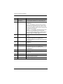
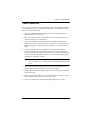
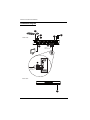
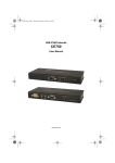
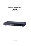
1
USB DVI Secure KVM Switch CS1182 / CS1184 User Manual www.aten.com CS1182 / CS1184 User Manual FCC, CE Information Federal Communication Commission Interference Statement: This equipment has been tested and found to comply with the limits for a Class B digital service, pursuant to Part 15 of the FCC rules. These limits are designed to provide reasonable protection against harmful interference in a residential installation. Any changes or modifications made to this equipment may void the user’s authority to operate this equipment. This equipment generates, uses, and can radiate radio frequency energy. If not installed and used in accordance with the instructions, may cause harmful interference to radio communications. However, there is no guarantee that interference will not occur in a particular installation. If this equipment does cause harmful interference to radio or television reception, which can be determined by turning the equipment off and on, the user is encouraged to try to correct the interference by one or more of the following measures: Reorient or relocate the receiving antenna; Increase the separation between the equipment and receiver; Connect the equipment into an outlet on a circuit different from that which the receiver is connected; Consult the dealer/an experienced radio/television technician for help. FCC Caution: Any changes or modifications not expressly approved by the party responsible for compliance could void the user's authority to operate this equipment. RoHS This product is RoHS compliant. SJ/T 11364-2006 The following contains information that relates to China. ii CS1182 / CS1184 User Manual User Information Online Registration Be sure to register your product at our online support center: International http://eservice.aten.com Telephone Support For telephone support, call this number: International 886-2-8692-6959 China 86-10-5255-0110 Japan 81-3-5615-5811 Korea 82-2-467-6789 North America 1-888-999-ATEN ext 4988 United Kingdom 44-8-4481-58923 User Notice All information, documentation, and specifications contained in this manual are subject to change without prior notification by the manufacturer. The manufacturer makes no representations or warranties, either expressed or implied, with respect to the contents hereof and specifically disclaims any warranties as to merchantability or fitness for any particular purpose. Any of the manufacturer's software described in this manual is sold or licensed as is. Should the programs prove defective following their purchase, the buyer (and not the manufacturer, its distributor, or its dealer), assumes the entire cost of all necessary servicing, repair and any incidental or consequential damages resulting from any defect in the software. The manufacturer of this system is not responsible for any radio and/or TV interference caused by unauthorized modifications to this device. It is the responsibility of the user to correct such interference. The manufacturer is not responsible for any damage incurred in the operation of this system if the correct operational voltage setting was not selected prior to operation. PLEASE VERIFY THAT THE VOLTAGE SETTING IS CORRECT BEFORE USE. iii CS1182 / CS1184 User Manual Package Contents The CS1182 / CS1184 package consists of: 1 CS1182 / CS1184 USB DVI Secure KVM Switch 1 Power Cord 1 User Instructions* Check to make sure that all of the components are present and in good order. If anything is missing, or was damaged in shipping, contact your dealer. Read this manual thoroughly and follow the installation and operation procedures carefully to prevent any damage to the switch or to any other devices on the CS1182 / CS1184 installation. * Features may have been added to the CS1182 / CS1184 since this manual was published. Please visit our website to download the most up to date version of the manual. © Copyright 2011–2014 ATEN® International Co., Ltd. Manual Part No. PAPE-0341-AT1G F/W Version: 1.0.064 Manual Date: 2014-02-27 ATEN and the ATEN logo are registered trademarks of ATEN International Co., Ltd. All rights reserved. All other brand names and trademarks are the registered property of their respective owners. iv CS1182 / CS1184 User Manual Contents FCC, CE Information. . . . . . . . . . . . . . . . . . . . . . . . . . . . . . . . . . . . . . . . . . ii SJ/T 11364-2006. . . . . . . . . . . . . . . . . . . . . . . . . . . . . . . . . . . . . . . . . . . . . ii User Information . . . . . . . . . . . . . . . . . . . . . . . . . . . . . . . . . . . . . . . . . . . . .iii Online Registration . . . . . . . . . . . . . . . . . . . . . . . . . . . . . . . . . . . . . . . .iii Telephone Support . . . . . . . . . . . . . . . . . . . . . . . . . . . . . . . . . . . . . . . .iii User Notice . . . . . . . . . . . . . . . . . . . . . . . . . . . . . . . . . . . . . . . . . . . . . .iii Package Contents. . . . . . . . . . . . . . . . . . . . . . . . . . . . . . . . . . . . . . . . . . . iv About This Manual . . . . . . . . . . . . . . . . . . . . . . . . . . . . . . . . . . . . . . . . . . vii Overview . . . . . . . . . . . . . . . . . . . . . . . . . . . . . . . . . . . . . . . . . . . . . . . vii Conventions . . . . . . . . . . . . . . . . . . . . . . . . . . . . . . . . . . . . . . . . . . . .viii Product Information. . . . . . . . . . . . . . . . . . . . . . . . . . . . . . . . . . . . . . . . . .viii Chapter 1. Introduction Overview . . . . . . . . . . . . . . . . . . . . . . . . . . . . . . . . . . . . . . . . . . . . . . . . . . . 1 Features . . . . . . . . . . . . . . . . . . . . . . . . . . . . . . . . . . . . . . . . . . . . . . . . . . . 2 Requirements . . . . . . . . . . . . . . . . . . . . . . . . . . . . . . . . . . . . . . . . . . . . . . . 3 Console . . . . . . . . . . . . . . . . . . . . . . . . . . . . . . . . . . . . . . . . . . . . . . . . . 3 Computers . . . . . . . . . . . . . . . . . . . . . . . . . . . . . . . . . . . . . . . . . . . . . . . 3 Cables . . . . . . . . . . . . . . . . . . . . . . . . . . . . . . . . . . . . . . . . . . . . . . . . . . 3 Operating Systems . . . . . . . . . . . . . . . . . . . . . . . . . . . . . . . . . . . . . . . . 4 Components . . . . . . . . . . . . . . . . . . . . . . . . . . . . . . . . . . . . . . . . . . . . . . . . 5 Front View . . . . . . . . . . . . . . . . . . . . . . . . . . . . . . . . . . . . . . . . . . . . . . . 5 Rear View . . . . . . . . . . . . . . . . . . . . . . . . . . . . . . . . . . . . . . . . . . . . . . . 5 Chapter 2. Hardware Setup Before You Begin . . . . . . . . . . . . . . . . . . . . . . . . . . . . . . . . . . . . . . . . . . . . 7 Stacking . . . . . . . . . . . . . . . . . . . . . . . . . . . . . . . . . . . . . . . . . . . . . . . . . . . 7 Grounding . . . . . . . . . . . . . . . . . . . . . . . . . . . . . . . . . . . . . . . . . . . . . . . . . . 8 Cable Connection . . . . . . . . . . . . . . . . . . . . . . . . . . . . . . . . . . . . . . . . . . . . 9 Installation Diagram. . . . . . . . . . . . . . . . . . . . . . . . . . . . . . . . . . . . . . . 10 Chapter 3. Operation Powering On . . . . . . . . . . . . . . . . . . . . . . . . . . . . . . . . . . . . . . . . . . . . . . . 11 Manual Switching . . . . . . . . . . . . . . . . . . . . . . . . . . . . . . . . . . . . . . . . . . . 11 Port ID Numbering. . . . . . . . . . . . . . . . . . . . . . . . . . . . . . . . . . . . . . . . 11 LED Display . . . . . . . . . . . . . . . . . . . . . . . . . . . . . . . . . . . . . . . . . . . . . . . 11 Chassis Intrusion Detection. . . . . . . . . . . . . . . . . . . . . . . . . . . . . . . . . 12 CAC Reader . . . . . . . . . . . . . . . . . . . . . . . . . . . . . . . . . . . . . . . . . . . . . . . 12 Appendix Safety Instructions. . . . . . . . . . . . . . . . . . . . . . . . . . . . . . . . . . . . . . . . . . . 13 v CS1182 / CS1184 User Manual General . . . . . . . . . . . . . . . . . . . . . . . . . . . . . . . . . . . . . . . . . . . . . . . . 13 Consignes de sécurité . . . . . . . . . . . . . . . . . . . . . . . . . . . . . . . . . . . . . . . 15 Général . . . . . . . . . . . . . . . . . . . . . . . . . . . . . . . . . . . . . . . . . . . . . . . . 15 Technical Support. . . . . . . . . . . . . . . . . . . . . . . . . . . . . . . . . . . . . . . . . . . 18 International . . . . . . . . . . . . . . . . . . . . . . . . . . . . . . . . . . . . . . . . . . . . 18 North America . . . . . . . . . . . . . . . . . . . . . . . . . . . . . . . . . . . . . . . . . . . 18 Specifications . . . . . . . . . . . . . . . . . . . . . . . . . . . . . . . . . . . . . . . . . . . . . . 19 Limited Warranty. . . . . . . . . . . . . . . . . . . . . . . . . . . . . . . . . . . . . . . . . . . . 20 vi CS1182 / CS1184 User Manual About This Manual This User Manual is provided to help you get the most from your CS1182 / CS1184 system. It covers all aspects of installation, configuration and operation. An overview of the information found in the manual is provided below. Overview Chapter 1, Introduction, introduces you to the CS1182 / CS1184 System. Its purpose, features and benefits are presented, and its front and back panel components are described. Chapter 2, Hardware Preparative Procedure, provides step-by-step instructions for setting up your installation. Chapter 3, Operation, explains the concepts involved in operating the CS1182 / CS1184. An Appendix, provides specifications and other technical information regarding the CS1182 / CS1184. vii CS1182 / CS1184 User Manual Conventions This manual uses the following conventions: Monospaced Indicates text that you should key in. [] Indicates keys you should press. For example, [Enter] means to press the Enter key. If keys need to be chorded, they appear together in the same bracket with a plus sign between them: [Ctrl+Alt]. 1. Numbered lists represent procedures with sequential steps. ♦ Bullet lists provide information, but do not involve sequential steps. → Indicates selecting the option (on a menu or dialog box, for example), that comes next. For example, Start → Run means to open the Start menu, and then select Run. Indicates critical information. Product Information For information about all ATEN products and how they can help you connect without limits, visit ATEN on the Web or contact an ATEN Authorized Reseller. Visit ATEN on the Web for a list of locations and telephone numbers: International http://www.aten.com North America http://www.aten-usa.com viii Chapter 1 Introduction Overview The CS1182 / CS1184 is NIAP-certified and passed the Evaluation Assurance Level 2 (EAL2+) requirements for Peripheral Sharing Switch (PSS) for Human Interface Devices (HIDs) Protection Profile v2.1, satisfying the latest security requisites set by the U.S. Department of Defense for peripheral switches. Compliance ensures maximum information security while sharing a single set of HIDs (keyboards, mouse, speakers, etc.) between multiple computers. Conformity with Protection Profile v2.1 certifies that other USB peripherals cannot be connected to the console ports of the CS1182 / CS1184, and that only a keyboard and mouse are accommodated, therefore providing high-level security, protection and safekeeping of data. Hardware security includes tamper-evident tape, chassis intrusion detection, and tamper-proof hardware, while software security includes restricted USB connectivity – non HIDs (Human Interface Devices) are ignored when switching – an isolated channel per port that makes it impossible for data to be transferred between secure and unsecure computers, and automatic clearing of the keyboard and mouse buffer. By combining physical security with controlled USB connectivity, the CS1182 / CS1184 gives you the means to consolidate multiple workstations of various security classification levels with one keyboard, monitor and mouse (KVM) console. Note: 1. The National Information Assurance Partnership (NIAP) is a United States government initiative to meet the security testing needs of IT consumers and manufacturers. It is operated by the National Security Agency (NSA) and the National Institute of Standards and Technology (NIST). 2. The CS1182 / CS1184 additionally satisfies Evaluation Assurance Level 2 (EAL2+) requirements for Peripheral Sharing Switch (PSS) for Human Interface Devices Protection Profile v2.1. 1 CS1182 / CS1184 User Manual Features 2/4-port USB DVI Dual-Link Secure KVM Switch Port selection via Pushbutton only (OSD, hotkey methods are not allowed) to enhance security One USB console controls 2/4 secure computers NIAP-certified – validated to EAL2+ security requirements Restricted USB connectivity – non HIDs (Human Interface Devices) are ignored when switching Isolated channel per port – makes it impossible for data to be transferred between computers Tamper-evident tape – provides a visual indication of any attempt to gain access to the switch’s internal components Chassis intrusion detection – if the cover is removed from the switch, the unit becomes inoperable and the LEDs flash Tamper-proof hardware – all integrated circuits are soldered directly to the circuit board to prevent tampering with the components Non-reprogrammable ROM – prevents tampering and attempts to reprogram the switch’s firmware Clears keyboard buffer – keyboard data is automatically cleared after transmission to the switch Video DynaSync – stores the console monitor’s EDID (Extended Display Identification Data) to optimize display resolution Multiplatform support – Windows 2000/XP/Vista, Linux, Mac, Sun Superior video quality – 2560x1600 (DVI Dual Link), 1920x1200 (DVI Single Link) and 2048x1536 (DVI-A) Rugged metal enclosure Built-in internal power Speaker and microphone support 2 Chapter 1. Introduction Requirements Console DVI monitor capable of the highest resolution that you will be using on any computer in the installation USB mouse USB keyboard Microphone and speaker Computers A DVI card USB Type A ports keyboard and mouse ports Cables The DVI-D KVM cable sets which are specifically designed to work with this switch are not supplied in the package and require a separate purchase. 3 CS1182 / CS1184 User Manual Operating Systems Suggested operating systems are shown in the table, below: OS Windows Linux UNIX Novell Version 2000, 2003, 2008, XP, Vista RedHat 9.0 and higher, Fedora Core 4 and higher SuSE 10 and higher Debian 3.1, 4.0 Ubuntu 7.04, 7.10 AIX 4.3 and higher FreeBSD 5.5 and higher Sun Solaris 8 and higher Netware 5.0 and higher Mac OS 9 and higher DOS 6.2 and higher Note: Supports Linux Kernel 2.6 and higher. 4 Chapter 1. Introduction Components Front View 2 1 3 4 5 Rear View 7 6 8 9 10 11 12 Note: The CS1184 has been used in these illustrations. The front and rear panels of the CS1182 and the CS1184 are the same, except the CS1182 has two ports/port selection pushbuttons and the CS1184 has four. 5 CS1182 / CS1184 User Manual No. Component Description 1 Port Selection Pushbuttons Pressing a Port Selection Pushbutton brings the focus to the computer attached to its corresponding port. 2 Port LEDs The Port LEDs are built into the Port Selection Pushbuttons. Online – Lights green to indicate that the computer attached to its corresponding port is up and running. Note: The green light for a given port is lit for as long as there is a powered on USB connection between the KVM switch and computer. Selected – Lights orange to indicate that the computer attached to its corresponding port has the KVM. Note: The Selected LEDs will flash constantly when a chassis intrusion is detected. See Chassis Intrusion Detection, page 12 for further details. 6 3 Reset Button Press this to reset the CS1182 / CS1184 to the default settings. 4 Audio Ports The cables from your main speakers and main microphone plug in here. The speakers and microphone plugged in here have priority over those in the rear panel. 5 Power LED Lights blue to indicate that the CS1182 / CS1184 is powered on. 6 USB Console Ports Your USB keyboard and mouse plug into these ports. 7 Audio Ports The cables from your main speakers and main microphone plug in here. The speakers and microphone plugged in here have priority over those in the rear panel. 8 Console Monitor Port The cable from your console monitor plugs in here. 9 KVM Port Section The custom KVM cables that attach to your computers plug in here. 10 Power Switch The power adapter cable plugs in here. 11 Power Socket This is a standard rocker switch that powers the CS1182 / CS1184 on and off. 12 Grounding Screw See Grounding, page 8 for further details. Chapter 2 Hardware Setup Before You Begin 1. Important safety information regarding the placement of this device is provided on page 13. Please review it before proceeding. 2. Make sure that the power to all devices connected to the installation are turned off. You must unplug the power cords of any computers that have the Keyboard Power On function. 3. A computer connected to the KVM switch should only be powered on after all of the connections to the device are made (DVI, USB and audio). Stacking The CS1182 / CS1184 features a rugged, metal enclosure which provides stability and allows the unit to stacked on the desktop.The unit can be placed on any level surface that can safely support its weight and the weight of the attached cables. Its enclosure is also strong and stable enough to support a monitor or other desktop item. Ensure that the surface is clean and free of materials that can block the exhaust vents or otherwise interfere with normal operation of the KVM switch. 7 CS1182 / CS1184 User Manual Grounding To prevent damage to your installation it is important that all devices are properly grounded. Use a grounding wire to ground the CS1182 / CS1184 by connecting one end of the wire to the grounding terminal, and the other end of the wire to a suitable grounded object. 8 Chapter 2. Hardware Setup Cable Connection To set up your CS1182 / CS1184 installation, refer to the installation diagram on the following page (the numbers in the diagrams correspond to the steps, below), and do the following: 1. Plug your USB keyboard and USB mouse into the USB console ports located on the unit’s rear panel. 2. Plug your console monitor into the DVI console port located in the unit’s rear panel and power on the monitor. 3. Plug your microphone and speakers into the console microphone and speaker jacks located on the unit’s front or rear panel. The microphone and speakers plugged into the front panel have priority over those in the rear panel. 4. Using a KVM cable set (not supplied in the package and should be purchased separately), plug the DVI connector into any available DVI socket in the KVM port section of the switch, then plug the accompanying USB, microphone and speaker connectors into their corresponding USB, microphone, and speaker sockets. Note: Verify that all the plugs are in the same KVM Port sockets (all in Port 1, all in Port 2, etc.). Each socket is marked with an appropriate icon. 5. At the other end of the cable, plug the USB, video, microphone, and speaker cables into their respective ports on the computer. 6. Check that the USB seal is still attached to the CAC reader port to prevent unintended usage. 7. Plug the female end of the power cord into the CS1182 / CS1184's power socket; plug the male end into an AC power source. 8. Turn on the product and check that the LEDs light up for 1 second. 9 CS1182 / CS1184 User Manual Installation Diagram 1 3 7 8 Rear View 2 4 USB DVI KVM Cable Set 5 USB DVI KVM Cable Set Front View 6 10 Chapter 3 Operation Powering On When you power on your computers, the CS1182 / CS1184 emulates both a mouse and keyboard on each port and allows your computers to boot normally. When you power on the CS1182 / CS1184, the default selected port at switch power on is the lowest port with a computer connected. The selected computer will be displayed on the console monitor. Note: The default connection is determined by the lowest numbered DVI connection that is powered on. Manual Switching For increased security, the CS1182 / CS1184 offers manual port-switching only. This is achieved by pressing the port selection pushbuttons located on the unit’s front panel. Press and release a port selection pushbutton to bring the KVM focus to the computer attached to its corresponding port (see Port ID Numbering, below). The Selected LED lights orange to indicate that the computer attached to its corresponding port has the KVM. Port ID Numbering Each KVM port on the CS1182 / CS1184 is assigned a port number (1–2 for the CS1182; 1–4 for the CS1184). The port numbers are marked on the rear of the switch. See Rear View, page 5. The port ID of a computer is derived from the KVM port number it is connected to. LED Display In addition to the Power LED, the CS1182 / CS1184 has port LEDs (Online and Selected) that are built into the port selection pushbuttons to indicate port operating status, as shown in the table below: 11 CS1182 / CS1184 User Manual LED Indication Power Lights blue to indicate that the CS1182 / CS1184 is powered on Online Lights green to indicate that the computer attached to its corresponding port is up and running. Note: The green light for a given port is lit for as long as there is a powered on USB connection between the KVM switch and computer. Selected Lights orange to indicate that the computer attached to its corresponding port has the KVM. Chassis Intrusion Detection To help prevent malicious tampering with the CS1182 / CS1184, the switch becomes inoperable and the Selected LEDs flash constantly when a chassis intrusion, such as the cover being removed, is detected. CAC Reader The usage of the CAC Reader port is not covered in this evaluation. Make sure the USB seal is in place to maintain the integrity of this device. 12 Appendix Safety Instructions General This product is for indoor use only. Read all of these instructions. Save them for future reference. Follow all warnings and instructions marked on the device. Do not place the device on any unstable surface (cart, stand, table, etc.). If the device falls, serious damage will result. Do not use the device near water. Do not place the device near, or over, radiators or heat registers. The device cabinet is provided with slots and openings to allow for adequate ventilation. To ensure reliable operation, and to protect against overheating, these openings must never be blocked or covered. The device should never be placed on a soft surface (bed, sofa, rug, etc.) as this will block its ventilation openings. Likewise, the device should not be placed in a built in enclosure unless adequate ventilation has been provided. Never spill liquid of any kind on the device. Unplug the device from the wall outlet before cleaning. Do not use liquid or aerosol cleaners. Use a damp cloth for cleaning. The device should be operated from the type of power source indicated on the marking label. If you are not sure of the type of power available, consult your dealer or local power company. The device is designed for IT power distribution systems with 230V phase-to-phase voltage. To prevent damage to your installation it is important that all devices are properly grounded. The device is equipped with a 3-wire grounding type plug. This is a safety feature. If you are unable to insert the plug into the outlet, contact your electrician to replace your obsolete outlet. Do not attempt to defeat the purpose of the grounding-type plug. Always follow your local/national wiring codes. Do not allow anything to rest on the power cord or cables. Route the power cord and cables so that they cannot be stepped on or tripped over. 13 CS1182 / CS1184 User Manual If an extension cord is used with this device make sure that the total of the ampere ratings of all products used on this cord does not exceed the extension cord ampere rating. Make sure that the total of all products plugged into the wall outlet does not exceed 15 amperes. To help protect your system from sudden, transient increases and decreases in electrical power, use a surge suppressor, line conditioner, or uninterruptible power supply (UPS). Position system cables and power cables carefully; Be sure that nothing rests on any cables. Never push objects of any kind into or through cabinet slots. They may touch dangerous voltage points or short out parts resulting in a risk of fire or electrical shock. Do not attempt to service the device yourself. Refer all servicing to qualified service personnel. If the following conditions occur, unplug the device from the wall outlet and bring it to qualified service personnel for repair. The power cord or plug has become damaged or frayed. Liquid has been spilled into the device. The device has been exposed to rain or water. The device has been dropped, or the cabinet has been damaged. The device exhibits a distinct change in performance, indicating a need for service. The device does not operate normally when the operating instructions are followed. CAUTION: RISK OF EXPLOSION IF BATTERY IS REPLACED BY AN INCORRECT TYPE. DISPOSE OF USED BATTERIES ACCORDING TO THE INSTRUCTIONS. 14 Appendix Consignes de sécurité Général Ce produit est destiné exclusivement à une utilisation à l’intérieur. Veuillez lire la totalité de ces instructions. Conservez-les afin de pouvoir vous y référer ultérieurement. Respectez l’ensemble des avertissements et instructions inscrits sur l’appareil. Ne placez jamais l’unité sur une surface instable (chariot, pied, table, etc.). Si l’unité venait à tomber, elle serait gravement endommagée. N’utilisez pas l’unité à proximité de l’eau. Ne placez pas l’unité à proximité de ou sur des radiateurs ou bouches de chaleur. Le boîtier de l’unité est doté de fentes et d’ouvertures destinées à assurer une ventilation adéquate. Pour garantir un fonctionnement fiable et protéger l’unité contre les surchauffes, ces ouvertures ne doivent jamais être bloquées ou couvertes. L’unité ne doit jamais être placée sur une surface molle (lit, canapé, tapis, etc.) car ses ouvertures de ventilation se trouveraient bloquées. De même, l’unité ne doit pas être placée dans un meuble fermé à moins qu'une ventilation adaptée ne soit assurée. Ne renversez jamais de liquides de quelque sorte que ce soit sur l’unité. Débranchez l’unité de la prise murale avant de la nettoyer. N’utilisez pas de produits de nettoyage liquide ou sous forme d’aérosol. Utilisez un chiffon humide pour le nettoyage de l’unité. L’appareil doit être alimenté par le type de source indiqué sur l’étiquette. Si vous n’êtes pas sûr du type d’alimentation disponible, consultez votre revendeur ou le fournisseur local d’électricité. Afin de ne pas endommager votre installation, vérifiez que tous les périphériques sont correctement mis à la terre. L’unité est équipée d’une fiche de terre à trois fils. Il s’agit d’une fonction de sécurité. Si vous ne parvenez pas à insérer la fiche dans la prise murale, contactez votre électricité afin qu’il remplace cette dernière qui doit être obsolète. N’essayez pas d’aller à l’encontre de l’objectif de la fiche de terre. Respectez toujours les codes de câblage en vigueur dans votre région/pays. 15 CS1182 / CS1184 User Manual L’équipement doit être installé à proximité de la prise murale et le dispositif de déconnexion (prise de courant femelle) doit être facile d’accès. La prise murale doit être installée à proximité de l’équipement et doit être facile d’accès. Veillez à ce que rien ne repose sur le cordon d’alimentation ou les câbles. Acheminez le cordon d’alimentation et les câbles de sorte que personne ne puisse marcher ou trébucher dessus. En cas d’utilisation d’une rallonge avec cette unité, assurez-vous que le total des ampérages de tous les produits utilisés sur cette rallonge ne dépasse pas l’ampérage nominal de cette dernière. Assurez-vous que le total des ampérages de tous les produits branchés sur la prise murale ne dépasse pas 15 ampères. Pour contribuer à protéger votre système contre les augmentations et diminutions soudaines et transitoires de puissance électrique, utilisez un parasurtenseur, un filtre de ligne ou un système d’alimentation sans coupure (UPS). Placez les câbles du système et les câbles d’alimentation avec précaution ; veillez à ce que rien ne repose sur aucun des câbles. Lors du branchement ou du débranchement à des blocs d’alimentation permettant la connexion à chaud, veuillez respecter les lignes directrices suivantes: Installez le bloc d’alimentation avant de brancher le câble d’alimentation à celui-ci. Débranchez le câble d’alimentation avant de retirer le bloc d'alimentation. Si le système présente plusieurs sources d’alimentation, déconnectez le système de l'alimentation en débranchant tous les câbles d'alimentation des blocs d'alimentation. N’insérez jamais d’objets de quelque sorte que ce soit dans ou à travers les fentes du boîtier. Ils pourraient entrer en contact avec des points de tension dangereuse ou court-circuiter des pièces, entraînant ainsi un risque d’incendie ou de choc électrique. N’essayez pas de réparer l’unité vous-même. Confiez toute opération de réparation à du personnel qualifié. Si les conditions suivantes se produisent, débranchez l’unité de la prise murale et amenez-la à un technicien qualifié pour la faire réparer: Le cordon d’alimentation ou la fiche ont été endommagés ou éraillés. Du liquide a été renversé dans l’unité. 16 Appendix L’unité a été exposée à la pluie ou à l’eau. L’unité est tombée ou le boîtier a été endommagé. Les performances de l’unité sont visiblement altérées, ce qui indique la nécessité d’une réparation. L’unité ne fonctionne pas normalement bien que les instructions d’utilisation soient respectées. N’utilisez que les commandes qui sont abordées dans le mode d’emploi. Le réglage incorrect d’autres commandes peut être à l’origine de dommages qui nécessiteront beaucoup de travail pour qu’un technicien qualifié puisse réparer l’unité. Ne connectez pas le connecteur RJ-11 portant la marque « Sensor » (Capteur) à un réseau de télécommunication public. 17 CS1182 / CS1184 User Manual Technical Support International For online technical support – including troubleshooting and documentation: http://eservice.aten.com For telephone support, See Telephone Support, page iii: North America Email Support Online Technical Support [email protected] Troubleshooting Documentation Software Updates Telephone Support http://www.aten-usa.com/support 1-888-999-ATEN ext 4988 When you contact us, please have the following information ready beforehand: Product model number, serial number, and date of purchase. Your computer configuration, including operating system, revision level, expansion cards, and software. Any error messages displayed at the time the error occurred. The sequence of operations that led up to the error. Any other information you feel may be of help. 18 Appendix Specifications Function Computer Connections CS1182 CS1184 2 4 Port Selection Connectors Pushbutton Console Keyboard 1 x USB Type-A F (Black) Video 1 x DVI-I Dual Link F (White) Mouse 1 x USB Type-A F (Black) Audio Speaker Microphone 2 x USB Type-B F (White) 4 x USB Type-B F (White) Video 2 x DVI-I Dual Link F (White) 4 x DVI-I Dual Link F (White) Speaker 2 x Mini Stereo Jack F (Green) 4 x Mini Stereo Jack F (Green) Microphone 2 x Mini Stereo Jack F (Pink) 4 x Mini Stereo Jack F (Pink) Power Selected Emulation Port Selection 1 (Blue) 2 (Green) 2 (Orange) 4 (Orange) 2 x Pushbuttons 4 x Pushbuttons 1 x Semi-recessed Pushbutton Power 1 x Rocker Keyboard / Mouse USB DVI Dual Link: 2560x1600; DVI Single Link: 1920x1200 DVI-A: 2048x1536 I/P Rating 100–240V AC; 50/60 Hz; 0.5A Power Consumption 120V / 5.1W; 230V / 5.1W Operating Temp. Humidity -20–60ºC 0–80% RH, Non-condensing Housing Weight Dimensions (L x W x H) 120V / 6.1W; 230V / 5.7W 0–40ºC Storage Temp Physical Properties 4 (Green) Reset Video Environment 1 x 3-prong AC Socket Power On Line Switches 2 x Mini Stereo Jack F (Pink;1 x front panel,1 x rear panel) Computer Keyboard/Mouse Audio LEDs 2 x Mini Stereo Jack F (Green;1 x front panel,1 x rear panel) Metal 2.06 kg 2.10 kg 34.9 x 16.9 x 6.06 cm 19 CS1182 / CS1184 User Manual Limited Warranty IN NO EVENT SHALL THE DIRECT VENDOR'S LIABILITY EXCEED THE PRICE PAID FOR THE PRODUCT FROM DIRECT, INDIRECT, SPECIAL, INCIDENTAL, OR CONSEQUENTIAL DAMAGES RESULTING FROM THE USE OF THE PRODUCT, DISK, OR ITS DOCUMENTATION. The direct vendor makes no warranty or representation, expressed, implied, or statutory with respect to the contents or use of this documentation, and especially disclaims its quality, performance, merchantability, or fitness for any particular purpose. The direct vendor also reserves the right to revise or update the device or documentation without obligation to notify any individual or entity of such revisions, or update. For further inquiries, please contact your direct vendor. 20 Index C Cables, 9 Cable Connection, 9 Components, 5 front view, 5 LEDs, 6 Port LEDs, 6 rear view, 5 D desktop mounting, 7 F Features, 2 G Grounding, 8 grounding screw, 6 L LED Display, 11 LEDs, 11 port LEDs, 6 Power LED, 6 M Manual Switching, 11 N National Information Assurance Partnership, 1 NIAP, 1 Normal Mode Powering On, 11 Chassis Intrusion Detection, 12 LED Display, 11 Manual Switching, 11 Port ID Numbering, 11 O Online Registration, iii P Port ID Numbering, 11 Powering On, 11 R Requirements, 3 cables, 3 computer, 3 console, 3 Operating Systems, 4 OS Support, 4 RoHS, ii S Safety Instructions General, 13 SJ/T 11364-2006, ii Specifications, 19 stacking, 7 System Requirements Computers, 3 T Technical Support, 18 Telephone support, iii U User Notice, iii 21