1
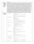
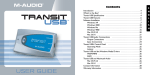
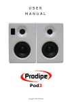
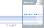
Table of Contents
Introduction
What’s in the Box?
Studiophile DX4 Features
Front and Rear Panel Features
Front
Rear
Installation
Precautions
Speaker Wire Connection
Connecting to a Computer Sound Card or Game Console
Setting the Mid-Boost EQ Switch
Placing the DX4
Technical Support & Contact Information
Warranty Information
Appendix A - Technical Specifications
Appendix B - Block Diagram
2
2
2
3
3
4
5
5
6
6
7
7
9
10
11
12
Introduction
Thank you for choosing the Studiophile DX4 professional desktop audio monitoring
system. Top recording engineers and producers in studios around the world use
M-Audio’s Studiophile Series monitors. With the Studiophile DX4s, you can enjoy the
same professional standard of audio quality right on your desktop.
The Studiophile DX4 has been designed and tested by veteran audio engineers to meet
your needs in a desktop audio monitoring environment. It is focused on the functional
goal of delivering pure, original sound without any additional coloration. The DX4
monitor is self-powered, directly accepting a line level signal from a variety of sources.
The Studiophile DX4 is designed to overcome all the limitations of conventional desktop
monitors within the digital audio environment. The DX4s match a custom tuned cabinet
design, optimized drivers and an advanced crossover technology with plenty of power,
insuring the highest-fidelity sound available from audio monitors of their size. And
M-Audio’s proprietary Opt Image wave guide technology assures improved and
defined stereo imaging. Studiophile DX4s bring your computer-based music, games
and DVDs to life.
•
What’s in the Box?
Your Studiophile DX4 box contains:
<
<
<
<
<
<
Two DX4 speakers (Left and Right)
One speaker wire
One 1/8 inch mini jack to RCA audio cable
One detachable AC power cord
User Manual
Actual test results of the DX4s you purchased
Studiophile DX4 Features
Woofer - The woofer unit is 4 inches in diameter with a magnetically shielded,
curved cone, high-temperature voice coil and closed cell foam damping. It is
designed to deliver balanced mid- and low- frequency response. The design is
used to react against the input signals accurately and to deliver even minimal
input precisely while minimizing distortion.
Tweeter - By employing a specially developed 1-inch mylar dome with magnetic
shielding, the tweeter can deliver distortion-free original sound and offer an
extremely natural response. It minimizes reaction time by using the specially
shaped mylar dome for excellent delivery, and also minimizes resonance by
adapting a unique internal damping technology. Also, incorporated into the
tweeter is the OptImage wave guide technology that improves stereo imaging.
Sub-Frequency Port - The hole in the rear panel is called a Sub-Frequency Port
and is designed to discharge extreme low frequencies.
2
Enclosure - Just as the other components do, the DX4’s enclosure plays an
important role. In order to provide more stable performance, the DX4’s
enclosure employs a special high-density MDF and unique interior
reinforcement designed to absorb vibration and impact generated under
extreme conditions.
Network and Power Amplifiers - The active equalization, crossover networks
and power amplifiers for the DX4 are specially designed for this woofer and
tweeter. The network properly distributes low, mid, and high frequencies to the
components in order to reduce distortion and loss of sound, thus achieving a
naturally balanced sound.
Mid-Boost Control - The back panel Mid-Boost control on the DX4s gives you
compensation for room EQs. It offers a great deal of control over the sound and
presence of the DX4 and make the DX4s very versatile for different spaces.
Front and Rear Panel Features
Front
Note: This image shows the Front panel of the Left Speaker. While
this panel contains the LF and HF Drivers (Woofer and Tweeter),
Power LED, Volume Control and Headphone Output Jack, the
Right Speaker‘s Front panel contains only LF and HF Drivers
(Woofer and Tweeter).
1.
HIGH-FREQUENCY DRIVER (TWEETER)
2. LOW-FREQUENCY DRIVER (WOOFER)
3. POWER INDICATOR LED: This blue LED lights lights the DX4’s power is turned on.
3
4. VOLUME CONTROL: This control determines the output volume level of the
DX4 speakers.
5. HEADPHONE OUTPUT JACK: This 1/8” jack outputs a stereo signal identical
to the DX4’s speaker output. When headphones are plugged into this jack, the
DX4 speakers are muted and headphone volume is controlled using the
volume control.
Rear
Note: This image shows the Rear panel of the Left Speaker. The Right
Speaker’s Rear panel contains only a single Speaker Terminal, for
connectioin to the Speaker Terminal of this Left Speaker).
1.
RCA Line INPUTS (L & R) - There are two RCA Line Inputs, marked as follows:
<
<
“L” - Left Channel Input (white jack) &
“R” - Right Channel Input (red jack).
These jacks accept standard RCA input connections with unbalanced wiring.
The included 1/8-inch mini jack-to-RCA audio cable allows users to connect the
DX4s to other equipment accepting 1/8-inch mini jack connections.
2. TRS INPUTS (L & R) - There are two RCA Line Inputs, marked as follows:
<
<
“L” - Left Channel Input) &
“R” - Right Channel Input).
These jacks accept a 1/4” connection with either balanced or unbalanced wiring.
Unbalanced 1/4” wiring can be done with either a two- or three-conductor (TS
or TRS) plug. A two-conductor (TS) plug automatically grounds the signal’s
4
negative input. A three-conductor (TRS) plug, wired unbalanced, provides the
option of leaving the negative input open or grounded. We recommend
grounding the unused negative input, which can be done by wiring the ring
and sleeve of the TRS plug together.
For balanced wiring, a three-conductor TRS plug is necessary.
The input wiring of the TRS input connector is as follows:
<
<
<
TRS TIP Signal positive (+)
TRS RING Signal negative (–)
TRS SLEEVE Signal ground (Shield)
Note: Input from the TRS and RCA connectors is summed together,
allowing both inputs to be used simultaneously.
3. MID-BOOST SELECTOR SWITCH: This 2-position switch selects the Mid-Boost
mode setting. The “Out” position setting produces a flat frequency response curve,
while the “In” position provides an added boost in the mid-range frequencies.
4. SPEAKER TERMINALS: The rear panel of both Left and Right Speaker enclosures
contains a spring-action speaker terminal. The included speaker wire should be
used to connect the terminal on the left speaker to the terminal on the right speaker.
5. POWER RECEPTACLE: Accepts a detachable 2-circuit line cord in order to
power the DX4 system.
6. PRODUCT LABEL: Contains your DX4’s model and serial number information.
7. POWER SWITCH: This switch turns the DX4 system on and off. The On position
is indicated by the white dot on the switch.
8. SUB FREQUENCY PORT: This port aids in the reproduction of very low
frequencies by discharging the frequencies below 60Hz.
Installation
In order to ensure optimal performance your DX4 system, please read carefully the
following instructions before beginning installation.
Precautions
Handling: The DX4 speakers are packaged tightly within the box, so your attention is
required when removing them. To avoid possible damage to the speaker, hold both
sides of the unit (not the front or the back) in order to pull it out of the box. The speaker
cones (the Woofer and the Tweeter) should not be touched in order to avoid damage
even after they are removed from the box. Please do not touch the speaker cones (the
Woofer or the Tweeter).
5
Connections: Connect the RCA or TRS inputs of your DX4 unit to the corresponding
computer sound card or game console outputs. We recommend that you use
high-quality cables for input connections. Be sure the power of the DX4 is off and turn
the volume of the DX4 down to a minimum before making the necessary connections.
Correct Power Operation: Since the DX4 contains amplifiers; it must be connected to
a power outlet using the detachable AC cable that is provided. Before connecting
power, please make sure that the voltage of the DX4 corresponds with the voltage you
are going to plug the power cord in.
WARNING! - Use of improper voltage may result in hazardous
conditions and/or damage to speaker components not covered by
speaker warranty.
Speaker Wire Connection
Use the speaker wires included in the DX4 package to connect the Right and Left
Speakers via the spring terminals.
Connecting to a Computer Sound Card or Game Console
Before connecting the DX4s, make sure that the device to be connected to the DX4, and
to the DX4 system itself has been powered off.
Plug the appropriate RCA, TRS or TS cable to the corresponding output connectors of the
computer sound card or game console.
6
Setting the Mid-Boost EQ Switch
This 2-position switch allows you to select either the “In” or “Out” Mid-Boost mode. The Out
mode produces a flat midrange response for normal monitoring and listening conditions.
The In mode will move the sound stage forward toward your listening position.
'Mid-Boost In'
Placing the DX4
Placing the speakers is one of the most important considerations in accurately
monitoring sound. To monitor with the DX4s performing at their maximum capacity, an
appropriate listening environment and correct placement are required. Please refer to
the following for DX4 placement.
1.
The two units and the listener should align to form a regular triangle. Refer to
the following diagram:
2. Position the monitors so that the tops of the woofers are level with your ears in
a normal listening environment. Refer to the following diagram:
7
3. Place the Left and Right DX4 units verticallyand right side up. Placing the DX4
monitors horizontally is not recommended.
Important: DO NOT place any obstacles that may block the flow of
air in front of or between the DX4 monitors. Also, remove reflective
materials such as glass, mirrors or metal from the monitoring
environment and place those materials away from the path of the
sound from the DX4s.
8
Technical Support & Contact Information
For additional help, contact M-Audio Technical Support by telephone, fax or e-mail. If
you have any questions, comments or suggestions about this or any M-Audio product,
we invite you to contact us at:
M-AUDIO Deutschland (Germany)
M-AUDIO U.S.
5795 Martin Road, Irwindale, CA 91706-6211, U.S.A.
Sales Information:
Sales Information (email):
Tech Support:
Tech Support (email):
Fax:
Internet Home Page:
626-633-9050
[email protected]
626-633-9055
[email protected]
626-633-9060
http://www.m-audio.com
Kuhallmand 34, D-74613 Ohringen, Germany
Sales Information:
49 7941 98 7000
Sales Information (email):
[email protected]
Technical Support:
49 7941 98 70030
Technical Support (email): [email protected]
Fax:
07941 98 70070
Internet Home Page:
http://www.m-audio.de
M-AUDIO U.K.
M-AUDIO Canada
Sales Information (phone):
44 (0) 1442 416590
Sales Information (fax):
44 (0) 1442 246832
Sales Information (email):
[email protected]
Technical Support (PC):
44 (0) 1309 671301
Technical Support (Mac):
44 (0) 1765 650072
Technical Support (email): [email protected]
Internet Home Page:
http://www.maudio.co.uk
Tel:
Fax:
Email:
Unit 5, Saracen Industrial Estate, Mark Road,
Hemel Hempstead, Herts HP2 7BJ, England
M-AUDIO France
418-872-0444
418-872-0034
[email protected]
Internet Home Page:
http://www.m-audio.ca
M-AUDIO Japan
Unit 5, Saracen Industrial Estate, Mark Road
Hemel Hempstead, Herts HP2 7BJ, England
Sales Information:
Sales Information (email):
Technical Support:
Technical Support (email):
Fax:
Internet Home Page:
1400 St-Jean Baptiste Ave. #150
Quebec City, QC G2E 5B7, Canada
0810 001 105
[email protected]
0820 00 731
[email protected]
44 (0) 144 224 6832
http://www.maudio.co.uk
9
Annex Buliding 6F, 2-18-10 Marunouchi
Naka-Ku, Nagoya 460-0002, Japan
Tel:
Fax:
Technical Support:
Email:
Internet Home Page:
81 52 218 3375
81 52 218 0875
0820 00 731
[email protected]
http://www.m-audio.co.jp
Warranty Information
Register online to receive FREE product updates and be entered to win FREE
M-Audio gear (www.m-audio.com/register).
M-AUDIO warrants that this product is free of defects in materials and workmanship
under normal use for a period of One (1) year from purchase date, so long as the
product is: owned by the original purchaser; the original purchaser has proof of
purchase from an authorized M-AUDIO dealer; and the purchaser has registered
his/her ownership of the product by sending in the completed warranty card.
This warranty explicitly excludes any included external non-integrated power supplies
and cables that may become defective as a result of normal wear and tear. In the event
that M-AUDIO receives written notice of defects in materials or workmanship from such
an original purchaser, M-AUDIO will replace the product, repair the product, or refund
the purchase price at its option.
In the event any repair is required, shipment to and from M-AUDIO and a nominal
handling charge shall be borne by the purchaser. In the event that repair is required, a
Return Authorization number must be obtained from M-AUDIO. After this number is
obtained, the unit should be shipped back to M-AUDIO in a protective package with a
description of the problem and the Return Authorization clearly written on the package.
In the event that M-AUDIO determines that the product requires repair because of user
misuse or regular wear, it will assess a fair repair or replacement fee. The customer will
have the option to pay this fee and have the unit repaired and returned, or not pay this
fee and have the unit returned un-repaired.
The remedy for breach of this limited warranty shall not include any other damages.
M-AUDIO will not be liable for consequential, special, indirect, or similar damages or
claims including loss of profit or any other commercial damage, even if its agents have
been advised of the possibility of such damages, and in no event will M-AUDIO’s
liability for any damages to the purchaser or any other person exceed the price paid for
the product, regardless of any form of the claim. M-AUDIO specifically disclaims all
other warranties, expressed or implied. Specifically, M-AUDIO makes no warranty that
the product is fit for any particular purpose.
This warranty shall be construed, interpreted, and governed by the laws of the state of
California. If any provision of this warranty is found void, invalid or unenforceable, it will
not affect the validity of the balance of the warranty, which shall remain valid and
enforceable according to its terms. In the event any remedy hereunder is determined
to have failed of its essential purpose, all limitations of liability and exclusion of
damages set forth herein shall remain in full force and effect.
10
Appendix A - Technical Specifications
Type: Two-way studio reference
LF Driver: 4-inch dia., magnetically-shielded with curved cone, high temperature voice
coil and damped closed cell foam surround.
HF Driver: 1-inch dia., magnetically-shielded with specially shaped mylar dome
Frequency Response: 70Hz - 20kHz
Crossover Frequencies: 2.2kHz
RMS SPL: 101.5dB @ 1 meter
Dynamic Range: >95dB
S/N Ratio: >90dB (typical, A-weighted)
Input Connectors: Left and Right RCA Line Input connectors, Left and Right TRS
balanced/unbalanced input connectors.
Polarity: Positive signal at + input produces outward low-frequency cone displacement
Dynamic Power: 18 watts/ 4 ohms with 2 channels connected
Input Impedance: 20k ohms balanced, 10k ohms unbalanced
Input Sensitivity: 100 mV pink noise input produces 90dBA output SPL at 1 meter with
volume control at maximum
Protection: RF interference, output current limiting, over temperature, turn on/off
transient, subsonic filter
Indicator: Blue power LED on front panel
Power Requirements: 120V/~60Hz, 230V/~50Hz or 100V/50Hz/60Hz; powered via
detachable 2-circuit line cord
Cabinet: vinyl-laminated MDF
Dimensions: 8.5 inch (H) x 5.75 inch (W) x 6.25 inch (D)
Weight: 12 lbs./pair (approx., without packing)
* Above specifications subject to change without notice
11
Appendix B - Block Diagram
LEFT SPEAKER
Balanced
Input Amp
R-Line
1” HF Driver
Mid-Boost
Switch
R-TRS
Master
Volume
2.2KHz
Mid-Boost
Power Amp
Crossover
Balanced
Input Amp
L-Line
4” LF Driver
L-TRS
Headphones
Mid-Boost
Power Amp
Speaker
Terminals
1” HF Driver
RIGHT SPEAKER
2.2KHz
Crossover
4” LF Driver
12