1
Ruckus Wireless™
ZoneFlex™ 7782 Dual Band 802.11n
Outdoor Access Point
Installation Guide
Part Number 800-70387-001 Rev B
Published December 2012
www.ruckuswireless.com
Contents
1
About this Installation Guide . . . . . . . . . . . . . . . . . . . . . . . . . . . . . . . . . . . . . . . . . . . . . . . . . 1
Using this Installation Guide . . . . . . . . . . . . . . . . . . . . . . . . . . . . . . . . . . . . . . . . . . . . . . . 1
Related Documentation . . . . . . . . . . . . . . . . . . . . . . . . . . . . . . . . . . . . . . . . . . . . . . . . . . . 3
Using ZoneDirector or FlexMaster to Manage the Access Point . . . . . . . . . . . . . . . . . . 3
Documentation Feedback . . . . . . . . . . . . . . . . . . . . . . . . . . . . . . . . . . . . . . . . . . . . . . . . . 3
2
Planning the 7782 Access Point Installation . . . . . . . . . . . . . . . . . . . . . . . . . . . . . . . . . . . . . 4
7782 AP Versions . . . . . . . . . . . . . . . . . . . . . . . . . . . . . . . . . . . . . . . . . . . . . . . . . . . . . . . . . 4
7782 . . . . . . . . . . . . . . . . . . . . . . . . . . . . . . . . . . . . . . . . . . . . . . . . . . . . . . . . . . . . . . . . . . 4
7782-S . . . . . . . . . . . . . . . . . . . . . . . . . . . . . . . . . . . . . . . . . . . . . . . . . . . . . . . . . . . . . . . . 5
7782-N . . . . . . . . . . . . . . . . . . . . . . . . . . . . . . . . . . . . . . . . . . . . . . . . . . . . . . . . . . . . . . . . 6
7782-E . . . . . . . . . . . . . . . . . . . . . . . . . . . . . . . . . . . . . . . . . . . . . . . . . . . . . . . . . . . . . . . . 6
AP Connectors and LEDs . . . . . . . . . . . . . . . . . . . . . . . . . . . . . . . . . . . . . . . . . . . . . . . . . . 7
Positioning the GPS Antenna . . . . . . . . . . . . . . . . . . . . . . . . . . . . . . . . . . . . . . . . . . . . . . . 9
Performing a Site Survey . . . . . . . . . . . . . . . . . . . . . . . . . . . . . . . . . . . . . . . . . . . . . . . . . 12
Planning the Physical Installation . . . . . . . . . . . . . . . . . . . . . . . . . . . . . . . . . . . . . . . . . . . 13
Notes on Power Sources . . . . . . . . . . . . . . . . . . . . . . . . . . . . . . . . . . . . . . . . . . . . . . . . 13
Deciding How to Power the AP . . . . . . . . . . . . . . . . . . . . . . . . . . . . . . . . . . . . . . . . . . . . 14
3
Preparing the 7782 Access Point at the Depot and Shipping to the Field . . . . . . . . . . . 15
Unpacking the AP . . . . . . . . . . . . . . . . . . . . . . . . . . . . . . . . . . . . . . . . . . . . . . . . . . . . . . . 15
Package Contents . . . . . . . . . . . . . . . . . . . . . . . . . . . . . . . . . . . . . . . . . . . . . . . . . . . . . . 16
Mounting Kit Contents . . . . . . . . . . . . . . . . . . . . . . . . . . . . . . . . . . . . . . . . . . . . . . . . . . 16
Powering the AP . . . . . . . . . . . . . . . . . . . . . . . . . . . . . . . . . . . . . . . . . . . . . . . . . . . . . . . . 17
Configuring the AP for Management by ZoneDirector . . . . . . . . . . . . . . . . . . . . . . . . . 18
Connecting the AP to ZoneDirector . . . . . . . . . . . . . . . . . . . . . . . . . . . . . . . . . . . . . . . 18
Verifying the AP Registration . . . . . . . . . . . . . . . . . . . . . . . . . . . . . . . . . . . . . . . . . . . . . 18
i
Configuring the AP for Management by FlexMaster or for Standalone Operation . . 20
Configuring the Administrative Computer . . . . . . . . . . . . . . . . . . . . . . . . . . . . . . . . . . 20
Connecting the AP to the Administrative Computer . . . . . . . . . . . . . . . . . . . . . . . . . 22
Logging In to the Access Point’s Web Interface . . . . . . . . . . . . . . . . . . . . . . . . . . . . . 22
Configuring Common Wireless Settings . . . . . . . . . . . . . . . . . . . . . . . . . . . . . . . . . . . 24
Configuring Wireless # Settings . . . . . . . . . . . . . . . . . . . . . . . . . . . . . . . . . . . . . . . . . . 26
(Optional) Setting the FlexMaster Server Address . . . . . . . . . . . . . . . . . . . . . . . . . . . 27
Verifying AP Operation . . . . . . . . . . . . . . . . . . . . . . . . . . . . . . . . . . . . . . . . . . . . . . . . . . . 29
Connecting the AP to the Network . . . . . . . . . . . . . . . . . . . . . . . . . . . . . . . . . . . . . . . . 29
Associating a Wireless Client with the AP . . . . . . . . . . . . . . . . . . . . . . . . . . . . . . . . . . 30
Checking the TR069 Status (FlexMaster Management Only) . . . . . . . . . . . . . . . . . . . 30
Disconnecting the AP from the Power Source and the Network . . . . . . . . . . . . . . . . 31
Disconnecting the AP from the Administrative Computer . . . . . . . . . . . . . . . . . . . . . 31
Restoring the Administrative Computer’s Network Settings . . . . . . . . . . . . . . . . . . . 31
Shipping the AP to the Field . . . . . . . . . . . . . . . . . . . . . . . . . . . . . . . . . . . . . . . . . . . . . . 32
4
Installing the 7782 Access Point in the Field . . . . . . . . . . . . . . . . . . . . . . . . . . . . . . . . . . . 33
Installation Components and Constraints . . . . . . . . . . . . . . . . . . . . . . . . . . . . . . . . . . . 33
Notes on Power Sources . . . . . . . . . . . . . . . . . . . . . . . . . . . . . . . . . . . . . . . . . . . . . . . . 33
Deploying the Access Point . . . . . . . . . . . . . . . . . . . . . . . . . . . . . . . . . . . . . . . . . . . . . . . 35
Connecting and Sealing the RJ-45 Cable . . . . . . . . . . . . . . . . . . . . . . . . . . . . . . . . . . 35
Mounting the Access Point . . . . . . . . . . . . . . . . . . . . . . . . . . . . . . . . . . . . . . . . . . . . . . . 36
Attaching the Hanger Mount to the Mounting Surface or Pole . . . . . . . . . . . . . . . . . 36
Assembling the Mounting Bracket and the AP . . . . . . . . . . . . . . . . . . . . . . . . . . . . . . 39
Attaching the AP and Mounting Bracket Assembly to the Hanger Mount . . . . . . . . 41
Earth Grounding the AP . . . . . . . . . . . . . . . . . . . . . . . . . . . . . . . . . . . . . . . . . . . . . . . . . 45
Mounting External Antennas (7782-E Only) . . . . . . . . . . . . . . . . . . . . . . . . . . . . . . . . . . 46
Typical External Antenna Deployments . . . . . . . . . . . . . . . . . . . . . . . . . . . . . . . . . . . . 46
About the 7782-E Access Points . . . . . . . . . . . . . . . . . . . . . . . . . . . . . . . . . . . . . . . . . . 47
Mounting and Connecting 5GHz and 2.4GHz External Antennas . . . . . . . . . . . . . . . 49
Mounting and Connecting an External GPS Antenna . . . . . . . . . . . . . . . . . . . . . . . . . 51
ii
Verifying Access Point Operation . . . . . . . . . . . . . . . . . . . . . . . . . . . . . . . . . . . . . . . . . . 52
Powering the AP . . . . . . . . . . . . . . . . . . . . . . . . . . . . . . . . . . . . . . . . . . . . . . . . . . . . . . . 52
Connecting the AP to the Network . . . . . . . . . . . . . . . . . . . . . . . . . . . . . . . . . . . . . . . . 57
Configuring the External Antenna Gain (7782-E Only) . . . . . . . . . . . . . . . . . . . . . . . . 58
Associating a Wireless Client with the AP . . . . . . . . . . . . . . . . . . . . . . . . . . . . . . . . . . 63
Checking the TR069 Status (FlexMaster Management Only) . . . . . . . . . . . . . . . . . . . 63
5
What to Do Next . . . . . . . . . . . . . . . . . . . . . . . . . . . . . . . . . . . . . . . . . . . . . . . . . . . . . . . . . . 64
Changing the Administrative Password . . . . . . . . . . . . . . . . . . . . . . . . . . . . . . . . . . . . . 64
Configuring the Security Settings . . . . . . . . . . . . . . . . . . . . . . . . . . . . . . . . . . . . . . . . . . 64
Configuring Advanced Settings and Features . . . . . . . . . . . . . . . . . . . . . . . . . . . . . . . . 64
Reading Related Documentation . . . . . . . . . . . . . . . . . . . . . . . . . . . . . . . . . . . . . . . . . . 64
Appendix A: Ruckus Wireless-Supplied and Customer-Ordered Parts . . . . . . . . . . . . . . . . . 65
Appendix B: Resetting the Access Point to Factory Default Settings . . . . . . . . . . . . . . . . . . 70
Appendix C: Installer Mounting Dimensions . . . . . . . . . . . . . . . . . . . . . . . . . . . . . . . . . . . . . . 71
Hanger Mount Template . . . . . . . . . . . . . . . . . . . . . . . . . . . . . . . . . . . . . . . . . . . . . . . . . 72
7782 Dimensions . . . . . . . . . . . . . . . . . . . . . . . . . . . . . . . . . . . . . . . . . . . . . . . . . . . . . . . . 73
Maximum Dimensions for Sector Mounting . . . . . . . . . . . . . . . . . . . . . . . . . . . . . . . . . . 75
Maximum Dimensions for Dome-Down Mounting . . . . . . . . . . . . . . . . . . . . . . . . . . . . 76
Appendix D: AC Power Cable Connector Assembly . . . . . . . . . . . . . . . . . . . . . . . . . . . . . . . . 77
iii
iv
1
About this Installation Guide
This document provides information on how to add Ruckus WirelessTM ZoneFlexTM 7782,
7782-S, 7782-N and 7782-E 802.11n Outdoor Access Points (APs) to your network. The
7782, 7782-S, 7782-N and 7782-E are collectively referred to in this guide as 7782 APs.
Topics covered in this guide include planning, basic configuring, and installing.
This guide is intended for use by those responsible for installing and setting up network
equipment. Consequently, it assumes a basic working knowledge of local area networking,
wireless networking, and wireless devices.
Using this Installation Guide
The 7782 AP installation is completed with four main steps. Each step includes some
substeps. Figure 1 shows the main steps, and Table 1 includes the substeps.
Figure 1.
Adding a 7782 AP to an existing Ruckus Wireless network flowchart
Planning
the Installation
Preparing at the Depot
and Sending to the Field
Installing the AP
in the Field
What to Do
Next
1
About this Installation Guide
Using this Installation Guide
Table 1.
Adding a 7782 AP to an Existing Ruckus Wireless network
Section
Heading
2
Planning the 7782 Access Point Installation
• 7782 AP Versions
• AP Connectors and LEDs
• Positioning the GPS Antenna
• Performing a Site Survey
• Planning the Physical Installation
• Deciding How to Power the AP
3
Preparing the 7782 Access Point at the Depot and Shipping to the
Field
• Unpacking the AP
• Powering the AP
• Configuring the AP for Management by ZoneDirector
• Configuring the AP for Management by FlexMaster or for
Standalone Operation
• Verifying AP Operation
• Shipping the AP to the Field
4
Installing the 7782 Access Point in the Field
• Installation Components and Constraints
• Deploying the AP
• Mounting the AP
• Mounting External Antennas (7782-E only)
• Verifying AP Operation
5
What to Do Next
• Changing the Administrative Password
• Configuring the Security Settings
• Configuring Advanced Settings and Features
• Reading Related Documentation
NOTE: The AP can be managed using an AP web browser interface, an AP command line
interface (CLI), a simple network management protocol (SNMP) interface, and Ruckus
Wireless ZoneDirectorTM and FlexMasterTM. This document contains configuring instructions using these interfaces, as appropriate.
2
About this Installation Guide
Related Documentation
Related Documentation
In addition to this guide, each Ruckus Wireless ZoneFlex 7782 802.11n Outdoor Access
Point documentation set includes the following:
■
■
■
User Guide: Provides detailed information on how to configure the Outdoor Access
Point (AP). The Outdoor Access Point User Guide is available for download on the
Ruckus Wireless Support Web site at
http://support.ruckuswireless.com/documents
Release Notes: Provides late-breaking information about the current software release,
including new features, enhancements, and known issues. If the information in the
Release Notes differs from the information in this guide, follow the instructions in the
Release Notes.
Online Help: Accessible from the AP’s Web interface, the Online Help provides
information that helps you configure the device from the Web interface.
Using ZoneDirector or FlexMaster to Manage the
Access Point
If you are planning to use either Ruckus Wireless FlexMasterTM or ZoneDirectorTM to
manage the AP, this guide describes the required steps that will enable the AP to report
to and communicate with FlexMaster or ZoneDirector successfully.
■
■
To set up the AP for management by FlexMaster, refer to “(Optional) Setting the
FlexMaster Server Address” on page 27.
To set up the AP for management by ZoneDirector, refer to “Configuring the AP for
Management by ZoneDirector” on page 18.
Documentation Feedback
Ruckus Wireless is interested in improving its documentation and welcomes your
comments and suggestions. You can email your comments to Ruckus Wireless at
[email protected]
When contacting us, please include the following information:
■
Document title
■
Document part number (on the cover page)
■
Page number (if appropriate)
For example:
■
ZoneFlex 7782 Wi-Fi Dual Band 802.11n Outdoor Access Point Installation Guide
■
Part number: 800-70387-001 Rev B
■
Page 49
3
Planning the 7782 Access Point Installation
7782 AP Versions
2
Planning the 7782 Access Point Installation
Before installing the 7782, it is helpful to verify the version and to plan the AP installation:
■
7782 AP Versions
■
AP Connectors and LEDs
■
Performing a Site Survey
■
Planning the Physical Installation
■
Deciding How to Power the AP
7782 AP Versions
•
•
•
•
7782 Omni
7782-S 120-Degree Sector
7782-N 30-Degree Narrow Sector
7782-E External Antenna
7782
The 7782 Omni (ordering part number 901-7782-xx01) is best deployed where internalantenna lateral beamforming can provide the greatest reach and throughput to a wide
coverage area, or provide the greatest distance between APs in a connecting device. See
Figure 2 for internal-antenna coverage patterns and see Figure 3 for a typical mesh
coverage pattern.
Figure 2.
7782 Omni coverage
Limited Reach
Excellent
Reach
Excellent
Reach
Good Reach
Elevation Plane Coverage, Side View
4
Azimuth Plane Coverage, Top View
Planning the 7782 Access Point Installation
7782 AP Versions
Figure 3.
7782 Mesh elevation plane coverage, side view
Excellent
Reach
Excellent
Reach
Excellent
Reach
7782-S
The 7782-S 120-Degree Sector (ordering part number 901-7782-xx51) is best deployed
where internal-antenna horizontal beamforming can provide extended reach and
throughput to a 120-degree coverage area. See Figure 4 for internal-antenna coverage
patterns.
Figure 4.
7782-S 120-Degree sector coverage
Extended
120º Reach
10º - 20º Downtilt
Recommended for
Extended Coverage
Extended
30º Vertical
Beamwidth
Azimuth Plane Coverage, Top View
Elevation Plane Coverage, Side View
5
Planning the 7782 Access Point Installation
7782 AP Versions
7782-N
The 7782-N 30-Degree Narrow Sector (ordering part number 901-7782-xx61) is best
deployed where internal-antenna narrow beamforming can provide exceptional coverage
to a narrow sector, or can support extended reach in a point-to-point deployment. See
Figure 5 for internal-antenna coverage patterns and see Figure 6 for a typical high-density
narrow-sector coverage pattern.
Figure 5.
7782-N Narrow sector or point-to-point coverage
Extended
30º Vertical
Beamwidth
Extended
30º Horizontal
Coverage
Azimuth Plane Coverage, Top View
Figure 6.
Elevation Plane Coverage, Side View
High-density narrow-sector coverage
30º Elevation or Azimuth
Coverage Areas, Side View
7782-E
The 7782-E External Antenna (ordering part number 901-7782-xx81) coverage is defined
by external antennas, up to three 2.4GHz and up to three 5GHz, and one optional GPS
antenna. These antennas can support operator-defined coverage areas and point-to-point
deployments. Refer to “Mounting External Antennas (7782-E Only)” on page 46 for more
information on 7782-E deployment options.
6
Planning the 7782 Access Point Installation
AP Connectors and LEDs
AP Connectors and LEDs
Figure 7 identifies the connectors and LEDs on all 7782 APs. Table 2 describes these
connectors and LEDs.
NOTE: 7782-E External Antenna APs also have seven extra N-type connectors on the top
cover. “About the 7782-E Access Points” on page 47 describes these extra connectors and
their functions.
Figure 7.
Connectors and LEDs on all APs - bottom view
PoE IN
PoE OUT
Reset Button
(inside case)
AC IN
Earth Ground
Screw
STATUS LED
POWER LED
Table 2.
Label
LEDs and connectors on all APs
Description
PoE IN RJ45 data Supports 10/100/1000Mbps connections, connects to the network and
connector
receives 802.3at Power over Ethernet (PoE) from the Ruckus Wireless
60W PoE injector. (Refer to “Appendix A: Ruckus Wireless-Supplied
and Customer-Ordered Parts” on page 65 to order a Ruckus Wireless
60W PoE injector.)
7
Planning the 7782 Access Point Installation
AP Connectors and LEDs
Table 2.
LEDs and connectors on all APs
Label
Description
PoE OUT RJ45
data connector
Supports 10/100/1000Mbps connections and PoE out. If the AP is
powered using AC or the Ruckus Wireless PoE injector (ordered
separately), then this port can supply 802.3af (15.4W) PoE to a
connected PoE-capable device (for example, an IP-based surveillance
camera).
Reset button
This button is inside the PoE OUT cable gland. Refer to “Appendix B:
Resetting the Access Point to Factory Default Settings” on page 70 to
access the reset button and reset the AP.
AC IN power
connector
You can use AC to supply power to the AP, in addition to using PoE.
STATUS LED
When the AP is operating in standalone mode:
• Amber: The WLAN service is up and at least one wireless client is
associated with the AP.
• Flashing amber: The WLAN service is up and no wireless clients are
currently associated with the AP.
When the AP is being managed by Ruckus Wireless ZoneDirector:
• Green: The AP is part of a mesh network (either as Root AP or Mesh
AP) and is connected to an uplink with good signal. If mesh
networking is disabled but the WLAN service is available, the
STATUS LED is also green.
• Fast flashing green: The AP is part of a mesh network (as Mesh AP)
and is connected to an uplink with fair signal.
• Slow flashing green: This Mesh AP is searching for an uplink or is
attempting to establish communication with ZoneDirector.
• Off: Mesh networking is disabled and the WLAN service is
unavailable.
POWER LED
8
• Off: No power is available, or the AP is not connected to a power
source.
• Red: The AP is powering on.
• Green: The AP is connected to a power source and has completed
its power-on sequence.
Planning the 7782 Access Point Installation
Positioning the GPS Antenna
Positioning the GPS Antenna
The 7782 Omni, 7782-S 120-Degree Sector, and 7782-N 30-Degree Narrow Sector APs all
include an internal GPS antenna, while the 7782-E External Antenna AP can be equipped
with a powered external GPS antenna.
In all cases, if the AP is to be used with the optional GPS feature enabled, the GPS antenna
must be mounted outdoors and have as clear a view of the sky as possible (as close as
possible to 360 degrees, and with no obstructing trees or buildings). The GPS antenna
must not be installed where it can be covered with snow buildup to avoid attenuating the
GPS signal. These requirements must be met to ensure that the GPS module can obtain
lock and provide accurate GPS time and position. If the GPS antenna has less than a clear
360-degree view of the sky, then the GPS module may experience degraded performance.
Figure 8.
7782, 7782-S and 7782-N GPS Antenna Location under Radome
9
Planning the 7782 Access Point Installation
Positioning the GPS Antenna
10
Figure 9.
7782, 7782-S and 7782-N Dome-Down Mount GPS Antenna Position
Figure 10.
7782, 7782-S and 7782-N Sector Mount GPS Antenna Position
Planning the 7782 Access Point Installation
Positioning the GPS Antenna
Figure 11.
7782-E External GPS Antenna Position
11
Planning the 7782 Access Point Installation
Performing a Site Survey
Performing a Site Survey
Perform a site survey to determine the optimal AP placement or maximum range,
coverage, and network performance. Ruckus Wireless Support can supply Site Survey best
practices information.
The location and orientation that you choose for the AP play a critical role in the
performance of your wireless network. In general, Ruckus Wireless recommends installing
the AP away from obstructions and sources of interference and ensuring that the AP’s best
coverage zone (refer to “7782 AP Versions” on page 4) is pointing in the general direction
of its wireless clients or associated bridge units.
When performing a site survey, consider the following factors:
■
■
■
■
■
12
Data rates: Range is generally inversely proportional to data rates. The maximum radio
range is achieved at the lowest workable data rate. Higher data rates will generally be
achieved at closer distances.
Antenna type and placement: Proper antenna configuration is a critical factor in
maximizing radio range. As a general rule, radio range is increased by mounting the
radio higher off of the ground with the AP oriented so that the dome is facing down
(for recommended orientation examples, refer to “7782 AP Versions” on page 4).
Physical environment: Clear or open areas provide better radio range than closed or
filled areas. The less cluttered the operating environment, the greater the wireless
range.
Obstructions, building materials, and sources of interference: Physical obstructions,
such as concrete pillars, steel beams, filing cabinets, buildings, or trees, can block or
hinder wireless communication. Avoid installing the AP in an environment where there
is an obstruction between sending and receiving devices. A number of machines and
electronic devices that emit radio waves – cranes, wireless phones, microwave ovens,
satellite dishes – interfere with and block wireless signals. Building materials used in
construction also influence radio signal penetration. For example, drywall construction
permits greater range than concrete blocks.
GPS Considerations: If the AP is to be used with the GPS feature, then the internal GPS
antenna (7782, 7782-N and 7782-S) or the optional powered external GPS antenna
(7782-E) must be mounted outdoors and have as clear a view of the sky as possible (as
close as possible to 360 degrees) to help the GPS module obtain lock and provide
accurate GPS time and position. (Refer to “Positioning the GPS Antenna” on page 9.)
The GPS antenna must not be installed where it can be covered with snow buildup to
avoid attenuating the GPS signal. If the GPS antenna has less than a clear 360-degree
view of the sky, then the GPS module may experience degraded performance.
Planning the 7782 Access Point Installation
Planning the Physical Installation
Planning the Physical Installation
The AP can be installed indoors or outdoors, such as on an interior wall or ceiling, on the
exterior roof overhang of a building, or on a streetlight pole.
Refer to Figure 30 for the components involved in a typical outdoor PoE installation. Refer
to Figure 31 for the components involved in a typical outdoor AC installation. Note which
components must be installed indoors and outdoors.
Ruckus Wireless strongly recommends 80mm - 130mm (3”-5”) drip loops on any cables
that are installed outdoors (for example, on an outdoor AP).
WARNING: When the AP is powered by AC and installed in a damp or wet location, the
AC branch circuit should be protected with a Residual-Current Circuit Breaker (RCCB), also
known as a Ground Fault Circuit Interrupter (GFCI), per National Electrical Code
Article 210.
Notes on Power Sources
■
■
■
■
■
The AP only requires one power source (either AC or PoE), but can be powered by AC
and PoE at the same time.
The AP may be powered by AC power or by PoE input using an 802.3af/at compliant
PSE (Power Sourcing Equipment) when the PoE Output is disabled. The PoE output is
enabled by default.
PoE OUT supports 802.3af (15.4W output) loads when the AP is operating off AC input
power or when operating off the PoE input port using a high-power 60W PoE Injector.
When AC powered and PoE is present, the AP draws power from the AC connection.
The 7782 PoE Output supports high power peripheral devices up to 25W, such as a
small cell or micro cell radio but only with the follow restrictions: the PoE Output cable
length between the 7782 and peripheral device is less than 8m (25 feet) and that the
7782 is operating off of AC Input power. High-power peripherals (up to 25W) may also
be powered by a 7782 operating from the PoE Input using a high power 60W injector,
provided that the PoE input cable length between the injector and 7782 is less than
8m (25 feet) and that the DC voltage at the 7782 PoE input connector is at least 44 VDC.
13
Planning the 7782 Access Point Installation
Deciding How to Power the AP
Deciding How to Power the AP
The AP can be powered using either AC power and/or Power over Ethernet (PoE). Use this
information and the information in “Planning the Physical Installation” on page 13 to
determine how to power the AP.
AC Power
An AC power cable connector is supplied with the AP. The customer supplies the countryspecific 3-wire AC power cable. The supported input voltages are:
■
Single Phase (L-N, PE): 120/240/250Vac 50/60Hz
■
Split Phase (L-L, PE): 208/230Vac 50/60Hz
The 7782 APs used in a mesh network generally use AC power.
Power over Ethernet
The customer orders a Ruckus Wireless PoE injector (part number 902-0180-XX00, where
XX is the country code). Note the following:
■
■
The AP can be powered by PoE 60W - to support PoE Out to 15.4W.
■
When AC powered and PoE is present, the AP draws power from the AC connection.
■
14
The AP may be powered by AC power or by PoE input using an 802.3af/at compliant
PSE (Power Sourcing Equipment) when the PoE Output is disabled. The PoE output is
enabled by default.
The 7782 PoE Output supports high power peripheral devices up to 25W, such as a
small cell or micro cell radio but only with the follow restrictions: the PoE Output cable
length between the 7782 and peripheral device is less than 8m (25 feet) and that the
7782 is operating off of AC Input power. High-power peripherals (up to 25W) may also
be powered by a 7782 operating from the PoE Input using a high power 60W injector,
provided that the PoE input cable length between the injector and 7782 is less than
8m (25 feet) and that the DC voltage at the 7782 PoE input connector is at least 44 VDC.
Preparing the 7782 Access Point at the Depot and Shipping to the Field
Unpacking the AP
3
Preparing the 7782 Access Point at the
Depot and Shipping to the Field
■
Unpacking the AP
■
AP Connectors and LEDs
■
Powering the AP
■
Configuring the AP for Management by ZoneDirector
■
Configuring the AP for Management by FlexMaster or for Standalone Operation
■
Verifying AP Operation
■
Shipping the AP to the Field
Unpacking the AP
1. Open the ZoneFlex AP package, and then carefully remove the contents.
2. Return all packing materials to the shipping box, and put the box away in a dry location.
3. Verify the 7782 Version:
• Part number 901-7782-xx01 = 7782 Omni
• Part number 901-7782-xx51 = 7782-S 120-Degree Sector
• Part number 901-7782-xx61 = 7782-N 30-Degree Narrow Sector
• Part number 901-7782-xx81 = 7782-E External Antenna
4. Verify that all items listed in “Package Contents” and “Mounting Kit Contents” are
included in the package. Check each item for damage. If any item is damaged or
missing, notify your authorized Ruckus Wireless sales representative.
NOTE: “Appendix A: Ruckus Wireless-Supplied and Customer-Ordered Parts” on
page 65 includes pictures and descriptions of these and other factory-orderable and
customer-supplied parts.
15
Preparing the 7782 Access Point at the Depot and Shipping to the Field
Unpacking the AP
Package Contents
A complete AP package contains all of the items listed below:
• ZoneFlex 7782 Outdoor Access Point
• One AC power cable input end connector
• Two M 25 data cable glands
• One green/yellow earth ground wire with ring terminal
• One 12mm M6x1 earth ground screw with split lock and flat washers
• One loop-and-eye safety cable
• Service Level Agreement/Limited Warranty Statement
• Regulatory Statement
• This Installation Guide
• One Mounting Kit (refer to “Mounting Kit Contents” for details)
Mounting Kit Contents
NOTE: “Appendix A: Ruckus Wireless-Supplied and Customer-Ordered Parts” on
page 65 includes pictures and descriptions of these and other factory-orderable and
customer-supplied parts.
The mounting kit includes the following:
• One wall- or pole-mount hanger mount
• One extension bracket
• One AP mounting bracket
• Two sets 40mm M8x1.25 hex bolt with split lock and flat washers
• Two SAE32 steel clamps, 2.5-inch diameter
• Four sets 0.250-28 x 0.625-inch hex bolt with split lock and flat washers
• Four sets 12mm M4x0.8 phillips pan-head screws with split lock and flat washers
16
Preparing the 7782 Access Point at the Depot and Shipping to the Field
Powering the AP
Powering the AP
NOTE: You only need to connect one type of power source at this point, even if you are
planning to use both PoE and AC power in your final deployment.
Apply power to the AP and check the LED operation using one of these two methods:
•
•
“Powering the 7782 with AC” on page 54
“Powering the Access Point with PoE” on page 56
17
Preparing the 7782 Access Point at the Depot and Shipping to the Field
Configuring the AP for Management by ZoneDirector
Configuring the AP for Management by
ZoneDirector
1. Collect required equipment and information:
•
•
One Cat5e or better Ethernet cable.
MAC address (12 alphanumeric digits) from the outside of the AP case.
2. Verify that the AP is powered on as described in “Powering the 7782 with AC” on
page 54 or “Powering the Access Point with PoE” on page 56.
Connecting the AP to ZoneDirector
NOTE: In addition to using Layer 2 auto discovery to enable the Access Point to register
with ZoneDirector, you can also use DHCP Option 43 or DNS. For more information, refer
to the ZoneDirector User Guide.
3. If you are powering the AP with PoE, then continue with Step 4. If you are powering
the AP with AC, then continue with Step 7.
4. Connect one end of the Ethernet cable to the Data In port on the PoE injector.
5. Connect the other end of the Ethernet cable to the same Layer 2 subnet as
ZoneDirector. The same Layer 2 subnet means that there should not be any router
between the AP and ZoneDirector.
The AP automatically discovers and registers with ZoneDirector.
6. You have completed connecting the AP to ZoneDirector. Continue with Step 10.
7. Connect one end of the Ethernet cable to the PoE IN port on the AP.
8. Connect the other end of the Ethernet cable to the same Layer 2 subnet as
ZoneDirector. The same Layer 2 subnet means that there should not be any router
between the AP and ZoneDirector.
The AP automatically discovers and registers with ZoneDirector.
9. You have completed connecting the AP to ZoneDirector. Continue with Step 10.
Verifying the AP Registration
10. Log in to ZoneDirector, and then go to the Monitor > Access Points page.
11. Look for the MAC address of the AP, and then check its Status column.
• If automatic approval is enabled, the Status column should show Connected.
• If automatic approval is disabled, click the Allow link that is on the same row as the
AP’s MAC address. This allows the AP to register with ZoneDirector.
18
Preparing the 7782 Access Point at the Depot and Shipping to the Field
Configuring the AP for Management by ZoneDirector
When the Status column shows Connected, this indicates that the AP has successfully
registered with ZoneDirector.
NOTE: If the ZoneDirector is set to Enable Mesh, it automatically assigns the 7782 AP as
a Root AP.
Continue with “Verifying AP Operation” on page 29.
19
Preparing the 7782 Access Point at the Depot and Shipping to the Field
Configuring the AP for Management by FlexMaster or for Standalone Operation
Configuring the AP for Management by FlexMaster
or for Standalone Operation
1. Collect required equipment and information:
•
•
•
•
An administrative computer (notebook computer) running Windows 7/Vista/XP/
2000 with one wireless 802.11b/g/n network card and one Ethernet card installed.
Mozilla Firefox 2.0 (or later) or Microsoft Internet Explorer 6.0 (or later) installed on
the administrative computer.
One Cat5e or better Ethernet cable.
MAC address (12 alphanumeric digits) from the outside of the AP case.
NOTE: You may need to disable the firewall between the AP and the FlexMaster server
to complete this procedure.
2. Verify that the AP is powered on as described in “Powering the AP” on page 17.
Continue with Configuring the Administrative Computer.
Configuring the Administrative Computer
NOTE: The following procedure is applicable if the administrative computer is running
Windows 7 or Windows XP. If you are using a different operating system, refer to the
documentation that was shipped with your operating system for information on how to
modify the computer’s IP address settings.
1. On your Windows 7 or Windows XP computer, open the Network Connections (or
Network and Dial-up Connections) control panel according to how the Start menu is
set up:
•
•
On Windows 7, click Start > Control Panel > Network and Internet > Network
and Sharing Center > Change Adapter Settings.
On Windows XP, click Start > Control Panel > Network Connections.
2. When the Network Connections window appears, right-click the icon for Local Area
Connection, and then click Properties.
NOTE: Make sure that you configure the Local Area Connection properties, not the
Wireless Network Connection properties.
3. When the Local Area Connection Properties dialog box appears, select Internet
Protocol (TCP/IP) or TCP/IPv4 in Windows 7 from the scrolling list, and then click
Properties. The Internet Protocol (TCP/IP) Properties dialog box appears.
20
Preparing the 7782 Access Point at the Depot and Shipping to the Field
Configuring the AP for Management by FlexMaster or for Standalone Operation
4. Write down all of the currently active network settings. You will need this information
later when you restore your computer to its current network configuration.
5. Click Use the following IP address, and then configure the IP address settings with
the values listed in Table 3. For a sample configuration, refer to Figure 12.
Table 3.
IP address
Configure your computer’s IP address settings
192.168.0.22 (or any address in the 192.168.0.x network—with the
exception of 192.168.0.1, which is the default IP address assigned to
the Access Point)
Subnet mask 255.255.255.0
Note: You can leave the Default Gateway and DNS server fields blank.
Figure 12.
Sample configuration in the Internet Protocol (TCP/IP) Properties dialog box
6. Click OK to save your changes and close the TCP/IP Properties dialog box.
7. Click OK again to close the Local Area Connection Properties dialog box.
Windows saves the IP address settings that you have configured. Continue with
Connecting the AP to the Administrative Computer.
21
Preparing the 7782 Access Point at the Depot and Shipping to the Field
Configuring the AP for Management by FlexMaster or for Standalone Operation
Connecting the AP to the Administrative Computer
1. If you are powering the AP with PoE, then continue with Step 2. If you are powering
the AP with AC, then continue with Step 5.
2. Connect one end of the Ethernet cable to the Data In port on the PoE injector.
3. Connect the other end of the Ethernet cable to the administrative computer either
directly or through a hub.
4. You have completed connecting the AP to the administrative computer. Continue with
“Logging In to the Access Point’s Web Interface” on page 22.
5. Connect one end of the Ethernet cable to the PoE IN port on the AP.
6. Connect the other end of the Ethernet cable to the administrative computer.
You have completed connecting the AP to the administrative computer. Continue with
Logging In to the Access Point’s Web Interface.
Logging In to the Access Point’s Web Interface
1. In the address or location bar, type the following address:
https://192.168.0.1
2. Press <Enter> on the keyboard to connect to the AP’s Web interface. A security alert
message appears.
3. Click Yes or OK or Proceed anyway (depending on the browser) to continue. The AP’s
login page appears.
Figure 13.
22
The ZoneFlex Access Point login page
Preparing the 7782 Access Point at the Depot and Shipping to the Field
Configuring the AP for Management by FlexMaster or for Standalone Operation
4. In User name, type super.
5. In Password, type sp-admin.
6. Click Login. The Web interface appears, displaying the Status > Device page.
Continue with Configuring Common Wireless Settings.
23
Preparing the 7782 Access Point at the Depot and Shipping to the Field
Configuring the AP for Management by FlexMaster or for Standalone Operation
Configuring Common Wireless Settings
The settings on the Common tab are required to enable wireless devices to associate with
the AP. The default wireless settings on the AP are listed in Table 4.
Table 4.
Default wireless settings
Setting
Default Value
SSID (network name)
Wireless 1 to Wireless 8 (8 WLANs)
Encryption (security)
Disabled on all WLANs
Default management IP address
192.168.0.1
NOTE: ZoneFlex 7782 has one 2.4GHz radio and one 5GHz radio. The wireless settings
for each radio need to be configured separately on the Web interface. To configure the
2.4GHz radio settings, click Configuration > Radio 2.4G. To configure the 5GHz radio
settings, click Configuration > Radio 5G.
1. On the left menu of the Web interface, click Configuration > Radio {2.4G/5G}. The
Common page appears (Figure 14).
Figure 14.
24
The Configuration > Radio 2.4 > Common tab
Preparing the 7782 Access Point at the Depot and Shipping to the Field
Configuring the AP for Management by FlexMaster or for Standalone Operation
2. Verify that the common wireless settings are configured as listed in Table 5.
Table 5.
Common wireless configuration
Setting
Recommended Value
Wireless Mode
• 2.4GHz (802.11b/g/n) for Configuration > Radio 2.4G > Common.
• 5GHz (802.11a/n) for Configuration > Radio 5G > Common.
Channel
SmartSelect.
Channel Width
20MHz.
Country Code
• If you purchased the AP in the United States of America, then this
value is fixed to United States at the factory and is not user
configurable.
• If you purchased the AP outside the United States of America, verify
that the value is set to your country or region. Selecting the correct
country code ensures that the AP uses only the radio channels
allowed in your country or region.
NOTE: The two radios on the ZoneFlex 7782 AP are always configured
with the same country code setting. If you change the country code for
Radio 2.4G, for example, the same change will be automatically
applied to Radio 5G.
External Antenna Always Enabled for 7782-E.
(7782-E only)
External Antenna • 2-antennas when only two external antennas are used for this band.
Antennas
• 3-antennas when three external antennas are used for this band.
(7782-E only)
3. If you made any changes to the Common tab, then click Update Settings.
4. Repeat Step 1 through Step 3 for Configuration > Radio 5G.
Continue with Configuring Wireless # Settings.
25
Preparing the 7782 Access Point at the Depot and Shipping to the Field
Configuring the AP for Management by FlexMaster or for Standalone Operation
Configuring Wireless # Settings
The settings on at least one Wireless # tab are required to enable wireless devices to
associate with the AP.
1. Click one of the Wireless # tabs. The selected Wireless # page appears (Figure 15).
Figure 15.
The Configuration > Radio 2.4 > Wireless 1 tab
2. In Wireless Availability, click Enabled.
3. In Broadcast SSID, click Enabled.
4. Clear the SSID box, and then type a unique and descriptive name that you want to call
this wireless network.
For example, you can type Ruckus Wireless AP. This SSID is the name that helps
users identify this wireless network in their wireless network connection application.
NOTE: You may also configure other wireless settings on this and other Wireless # tabs
(in addition to the settings described above), although it is not necessary for completing
the AP installation.
5. Click Update Settings. You have completed configuring the basic wireless settings of
the AP.
26
Preparing the 7782 Access Point at the Depot and Shipping to the Field
Configuring the AP for Management by FlexMaster or for Standalone Operation
If you are configuring the AP for management by FlexMaster, then continue with
“(Optional) Setting the FlexMaster Server Address” on page 27. If you are configuring the
AP for standalone operation, then continue with “Disconnecting the AP from the Administrative Computer” on page 31.
(Optional) Setting the FlexMaster Server Address
When you have a FlexMaster server installed on the network and you intend to use
FlexMaster to manage the AP, you can set the FlexMaster server address at this point.
Before starting this procedure, make sure you obtain the correct FlexMaster server URL.
NOTE: In addition to setting the FlexMaster server URL manually on the AP, you can also
use DHCP Option 43 or DNS to point the AP to the FlexMaster server. For more
information, refer to the FlexMaster User Guide.
1. On the menu, click Administration > Management.
2. Scroll down the page to the TR069 / SNMP Management Choice section (Figure 16).
Figure 16.
Type the FlexMaster server URL
27
Preparing the 7782 Access Point at the Depot and Shipping to the Field
Configuring the AP for Management by FlexMaster or for Standalone Operation
3. Verify that the Auto option is selected.
4. In FlexMaster Server URL, type the URL of the FlexMaster server on the network. You
can use either http or https to connect to the URL and include either the host name
or IP address of the FlexMaster server in the URL. The following are examples of valid
FlexMaster server URLs:
http://flexmaster/intune/server
https://flexmaster/intune/server
http://192.168.20.1/intune/server
https://192.168.20.1/intune/server
5. Click Update Settings to save your changes. You have completed setting the
FlexMaster server address on the AP.
NOTE: Instructions on how to verify that the AP and FlexMaster can communicate with
each other are provided in “Checking the TR069 Status (FlexMaster Management Only)”
on page 30.
Continue with Verifying AP Operation.
28
Preparing the 7782 Access Point at the Depot and Shipping to the Field
Verifying AP Operation
Verifying AP Operation
Ruckus Wireless recommends that you verify that the AP is operating correctly.
NOTE: You can perform these verification tasks indoors.
To verify that the AP is operating correctly, perform the following procedures:
■
Connecting the AP to the Network
■
Associating a Wireless Client with the AP
■
Checking the TR069 Status (FlexMaster Management Only)
■
Disconnecting the AP from the Power Source and the Network
■
Disconnecting the AP from the Administrative Computer
■
Restoring the Administrative Computer’s Network Settings
Connecting the AP to the Network
This procedure assumes that you have already powered the AP as described in “Powering
the AP” on page 17.
NOTE: You only need to connect one type of power source at this point, even if you are
planning to use both PoE and AC power in your final deployment.
The AP can connect to the network using data cables, or can connect to the network using
wireless backhaul if it is part of a mesh network.
NOTE: If the ZoneDirector is set to Enable Mesh, ZoneDirector automatically assigned
the 7782 AP as a Root AP while “Configuring the AP for Management by ZoneDirector”
on page 18.
1. If the AP is part of an available mesh network, continue with Step 2. If the AP is using
AC power, then continue with Step 4. If the AP is using PoE, then continue with Step 6.
2. When the AP has been configured as Root AP, and is powered up and does not find a
wired connection back to its ZoneDirector, it automatically looks for another Root AP.
When it finds another AP in the mesh network, it automatically provisions itself as a
Mesh AP in the mesh network.
3. Continue with “Associating a Wireless Client with the AP” on page 30.
4. Connect the Ethernet cable from your network’s router or switch to the PoE IN port on
the AP.
5. Continue with “Associating a Wireless Client with the AP” on page 30.
29
Preparing the 7782 Access Point at the Depot and Shipping to the Field
Verifying AP Operation
6. Connect the Ethernet cable from the Data In port on the PoE injector to your network’s
router or switch.
Continue with Associating a Wireless Client with the AP.
Associating a Wireless Client with the AP
1. In the client device's wireless interface, select the SSID configured in the “Configuring
Wireless # Settings” on page 26 section.
2. Connect the client device to the selected WLAN SSID.
After the wireless client successfully connects to the wireless LAN, continue with “Checking
the TR069 Status (FlexMaster Management Only)” on page 30 or “Disconnecting the AP
from the Power Source and the Network” on page 31.
Checking the TR069 Status (FlexMaster Management
Only)
If you configured the AP to report to a FlexMaster server on the network (“(Optional)
Setting the FlexMaster Server Address” on page 27), then make sure you verify that the
AP can successfully communicate with the FlexMaster server. You can do this by checking
the TR069 status on the AP’s web interface.
1. In the AP’s web interface, go to the Administration > Management page.
2. Scroll down to the TR069 Status section.
3. Check the value for Last successful contact. If it shows a date in green, then the AP
was able to communicate successfully with FlexMaster.
Continue with Disconnecting the AP from the Power Source and the Network.
30
Preparing the 7782 Access Point at the Depot and Shipping to the Field
Verifying AP Operation
Disconnecting the AP from the Power Source and the
Network
1. Disconnect the AP from the power source (either from the PoE injector or AC power
source).
2. Verify that the POWER LED is off.
3. Disconnect the Ethernet cable that runs to the AP’s PoE IN RJ45 port from your
network’s router or switch.
Continue with Disconnecting the AP from the Administrative Computer.
Disconnecting the AP from the Administrative Computer
1. If not already done, disconnect the AP from the power source (either from the AC
power source or PoE injector).
2. Verify that the POWER LED is off.
3. Disconnect the Ethernet cable from the administrative computer’s Ethernet port.
Continue with Restoring the Administrative Computer’s Network Settings.
Restoring the Administrative Computer’s Network
Settings
If the administrative computer’s network settings were changed as described in “Configuring the Administrative Computer” on page 20 and you do not want to change the
network settings back now, then continue with “Shipping the AP to the Field” on page 32.
If you do want to change the network settings back now, continue with the following steps:
NOTE: You may need to enable the firewall between the AP and the FlexMaster server
to complete this procedure.
1. On your Windows 7 or Windows XP computer, open the Network Connections (or
Network and Dial-up Connections) control panel according to how the Start menu is
set up:
•
•
On Windows 7, click Start > Control Panel > Network and Internet > Network
and Sharing Center > Change Adapter Settings.
On Windows XP, click Start > Control Panel > Network Connections.
2. When the Network Connections window appears, right-click the icon for Local Area
Connection, and then click Properties.
3. When the Local Area Connection Properties dialog box appears, select Internet
Protocol (TCP/IP) from the scrolling list, and then click Properties. The TCP/IP
Properties dialog box appears.
31
Preparing the 7782 Access Point at the Depot and Shipping to the Field
Shipping the AP to the Field
4. Restore the computer’s network settings by typing the original IP address settings in
the TCP/IP Properties dialog box.
5. In the TCP/IP Properties dialog box, click OK to close it.
6. Click OK again to close the Local Area Connection Properties dialog box.
You are now ready to ship the AP. Continue with Shipping the AP to the Field.
Shipping the AP to the Field
After you have prepared the AP as described earlier in this section, repackage the AP and
its mounting kit in the original shipping container and ship it to its final installation site.
Continue with “Installing the 7782 Access Point in the Field” on page 33.
32
Installing the 7782 Access Point in the Field
Installation Components and Constraints
4
Installing the 7782 Access Point in the
Field
Before installing the 7782 AP, Ruckus Wireless recommends that you first complete the
procedures described in “Planning the 7782 Access Point Installation” on page 4 and
“Preparing the 7782 Access Point at the Depot and Shipping to the Field” on page 15.
Completing these procedures ensures that the AP installation has been planned, and that
the AP has been prepared for installation.
Continue with the following procedures:
■
Installation Components and Constraints
■
Deploying the Access Point
■
Mounting the Access Point
■
Mounting External Antennas (7782-E Only)
■
Verifying Access Point Operation
Installation Components and Constraints
■
■
■
■
■
The AP can be installed indoors or outdoors, such as on an interior wall or ceiling, on
the exterior roof overhang of a building, or on a streetlight pole.
Refer to Figure 30 for the components involved in a typical outdoor PoE installation.
Refer to Figure 31 for the components involved in a typical outdoor AC installation.
Note which components must be installed indoors and outdoors.
Ruckus Wireless strongly recommends 80mm - 130mm (3”-5”) drip loops on any cables
that are installed outdoors (for example, into the outdoor AP and into a building).
The AP can be powered using either AC power and/or Power over Ethernet (PoE).
• AC Power: An AC power cable connector is supplied with the AP. The customer
supplies the country-specific 3-wire AC power cable. The supported input voltages
are: Single Phase (L-N, PE): 120/240/250Vac 50/60Hz, and Split Phase (L-L, PE): 208/
230Vac 50/60Hz.
• Power over Ethernet: The customer orders a Ruckus Wireless PoE injector (part
number 902-0180-XX00, where XX is the country code).
The 7782 APs used in a mesh network generally use AC power.
Notes on Power Sources
■
■
The AP only requires one power source (either AC or PoE), but can be powered by AC
and PoE at the same time.
The AP may be powered by AC power or by PoE input using an 802.3af/at compliant
PSE (Power Sourcing Equipment) when the PoE Output is disabled. The PoE output is
enabled by default.
33
Installing the 7782 Access Point in the Field
Installation Components and Constraints
■
■
■
PoE OUT supports 802.3af (15.4W output) loads when the AP is operating off AC input
power or when operating off the PoE input port using a high-power 60W PoE Injector.
When AC powered and PoE is present, the AP draws power from the AC connection.
The 7782 PoE Output supports high power peripheral devices up to 25W, such as a
small cell or micro cell radio but only with the follow restrictions: the PoE Output cable
length between the 7782 and peripheral device is less than 8m (25 feet) and that the
7782 is operating off of AC Input power. High-power peripherals (up to 25W) may also
be powered by a 7782 operating from the PoE Input using a high power 60W injector,
provided that the PoE input cable length between the injector and 7782 is less than
8m (25 feet) and that the DC voltage at the 7782 PoE input connector is at least 44 VDC.
WARNING: Only trained and qualified installers should be allowed to install, replace, or
service this equipment.
The professional installer is responsible for the proper installation and configuration of this
AP. The AP installation must comply with local regulatory requirements, especially with
those regulating operation near military and/or weather radar systems.
WARNING: Installation of this equipment must comply with local and national electrical
codes.
CAUTION: Make sure that you form a 80mm - 130mm (3”-5”) drip loop in any cable that
is attached to the AP or to the building. This will prevent water from running along the
cable and entering the AP or the building where the cable terminates.
CAUTION: Be sure that grounding is available and that it meets local and national
electrical codes. For additional lightning protection, use lightning rods and lightning
arrestors.
.
CAUTION: Make sure that proper lightning surge protection precautions are taken
according to local electrical code.
34
Installing the 7782 Access Point in the Field
Deploying the Access Point
Deploying the Access Point
In this section, you will mount the AP in its final mounting location. Perform the following:
■
Connecting and Sealing the RJ-45 Cable
■
Connecting the AP to the Network
Connecting and Sealing the RJ-45 Cable
The AP comes with two sets of RJ-45 waterproof connectors. To complete this step, you
will need one RJ-45 cable (two if you plan to use both the PoE IN and PoE OUT ports)
and the RJ-45 waterproof connector assembly.
1. Take out one of the two plastic bags containing the RJ-45 waterproof connector
assembly.
2. Feed the end of the RJ-45 cable through the sealing nut, rubber O-ring, and clamping
ring assembly as shown in Figure 17.
Figure 17.
RJ-45 waterproof connector assembly (P/N 902-0183-0000)
Clamping ring assembly
Rubber O-ring
Sealing nut
3. Connect the RJ-45 cable to the PoE IN port on the AP.
4. Wrap the clamping ring assembly around the rubber O-ring. Make sure that the
clamping ring assembly fully encloses the rubber O-ring.
5. Seat the clamping ring assembly and rubber O-ring in the cable gland base.
6. Hand-tighten the sealing nut.
7. If you are using both the PoE IN and PoE OUT ports, then assemble the second
waterproof connector by repeating Step 1 through Step 6.
Continue with Mounting the Access Point.
35
Installing the 7782 Access Point in the Field
Mounting the Access Point
Mounting the Access Point
CAUTION: When you are planning to connect external 5GHz antennas to the AP, mount
the AP so the external antennas are pointing up.
1. Collect the following items:
•
•
Bracket mounting kit (see “Mounting Kit Contents” on page 16)
When required, a loop-and eye safety cable (refer to “Appendix A: Ruckus WirelessSupplied and Customer-Ordered Parts” on page 59)
If you are mounting the AP on a flat surface, then you will also need:
• Customer-supplied wall anchors rated to withstand 128 N or 28.8 lbf (required to
withstand wind loads of 266km/h or 165mph)
• Tools required by the customer-supplied wall anchor kit
If you are mounting the AP on a pipe or pole, then you will also need:
• A 30mm to 60mm (1.18" to 2.36") pipe or pole
• Two steel clamps (supplied with the AP)
• 10mm flathead screwdriver
Continue with Attaching the Hanger Mount to the Mounting Surface or Pole.
Attaching the Hanger Mount to the Mounting Surface or
Pole
The procedure for attaching the bracket to the mounting surface depends on whether you
are mounting the AP to a flat surface or a pole:
■
Attaching the Hanger Mount to a Flat Surface
■
Attaching the Hanger Mount to a Pole
Attaching the Hanger Mount to a Flat Surface
WARNING: Ruckus Wireless strongly recommends that you wear eye protection before
drilling holes on the mounting surface.
1. Place the hanger mount at the exact location on the mounting surface where you want
to mount the AP.
NOTE: If you do not have the hanger mount available, you can use the hanger mount
template in “Appendix C: Installer Mounting Dimensions” on page 71.
2. Use the screw holes on the hanger mount as a template to mark the locations of the
mounting holes.
36
Installing the 7782 Access Point in the Field
Mounting the Access Point
3. Remove the hanger mount or template from the mounting surface.
4. Follow the instructions in the customer-supplied wall anchor kit to attach the hanger
mount to the flat surface.
5. If required, then thread the safety cable around the hanger mount and thread the eye
end through the loop end.
Figure 18.
Looping the optional safety cable around the hanger mount
Hanger
Mount
Safety
Cable
Eye
End
Continue with “Assembling the Mounting Bracket and the AP” on page 39.
Attaching the Hanger Mount to a Pole
The hanger mount can be attached vertically or horizontally on a 30mm to 60mm (1.18"
to 2.36") pole.
NOTE: Figure 19 shows the hanger mount attached horizontally, which allows AP azimuth
adjustments. To allow AP elevation adjustments, rotate the hanger mount 90º and install
vertically on the pole.
1. Insert the open end of one steel clamp into the upper two tabs on the hanger mount.
2. Take the other steel clamp and insert it into the lower two tabs on the hanger mount.
3. Use the clamps to attach the hanger mount to the pole (see Figure 19).
37
Installing the 7782 Access Point in the Field
Mounting the Access Point
Figure 19.
Attaching the hanger mount to a vertical pole
NOTE: Hanger mount shown attached
horizontally to allow AP azimuth
adjustments. Attach the hanger mount
vertically to allow AP elevation
adjustments.
4. Using a 10mm flathead screwdriver, tighten the clamp locks to secure the hanger mount
to the pole. Screw torque value must be 1.1-1.2 N.m or 9.7-10.6 in-lbs.
5. If required, then thread the safety cable around the hanger mount and thread the eye
end through the loop end.
Figure 20.
Looping the optional safety cable around the hanger mount
Hanger
Mount
Safety
Cable
Eye
End
Continue with “Assembling the Mounting Bracket and the AP” on page 39.
38
Installing the 7782 Access Point in the Field
Mounting the Access Point
Assembling the Mounting Bracket and the AP
1. Place the mounting bracket onto the flat side of the AP so that the four screw holes on
the bracket align with the four screw holes on the AP. Make sure that the longer ends
of the mounting bracket point away from the AP PoE and AC IN connectors as shown
in Figure 21.
Figure 21.
Positioning the mounting bracket on the Access Point
39
Installing the 7782 Access Point in the Field
Mounting the Access Point
2. If required, then push one of the four 0.250-28 bolts with washers through the safety
cable eye end as shown in Figure 22.
Figure 22.
AP
Mounting
Bracket
Attaching the safety cable and mounting bracket to the Access Point
Access
Point
Safety
Cable
Eye
3. Insert four 0.250-28 bolts with washers (supplied with the AP) into the screw holes on
the AP mounting bracket.
4. Using a 7/16” wrench, tighten the four bolts to secure the AP mounting bracket to the
AP. Bolt torque value must be 2.5-3.0 N.m or 22-27 in-lbs.
You have assembled the AP and its AP mounting bracket. Continue with Attaching the AP
and Mounting Bracket Assembly to the Hanger Mount.
40
Installing the 7782 Access Point in the Field
Mounting the Access Point
Attaching the AP and Mounting Bracket Assembly to the
Hanger Mount
There are two ways to attach the 7782 AP and AP mounting bracket assembly to the
mounting bracket, depending on the antenna directivity that you want to use.
NOTE: The 7782-E AP can be mounted in any orientation, as long as the external GPS
antenna can be mounted outdoors and pointed up or toward a mostly-unobstructed view
of the sky.
■
■
Sector Mounting -- This type of mounting uses the AP mounting bracket only.
Dome-Down Mounting -- This type of mounting uses the AP mounting bracket with
the extension bracket.
Sector Mounting
1. Place the AP mounting bracket attached to the AP on top of the hanger mount so that
the indexed teeth and screw holes on both are aligned (Figure 23).
Figure 23.
Sector mounting
NOTE: Hanger mount shown attached
horizontally to allow AP azimuth
adjustments. Attach the hanger mount
vertically to allow AP elevation
adjustments.
41
Installing the 7782 Access Point in the Field
Mounting the Access Point
2. Insert an M8 hex bolt into the vertical screw hole on the mounting bracket.
3. Finger tighten the hex bolt until it passes through the screw hole on the hanger mount.
4. Adjust the orientation of the AP as required.
NOTE: If the GPS feature is to be used on this AP, then make sure that the GPS antenna
is mounted outdoors and pointed up or toward a mostly-unobstructed view of the sky as
described in “Positioning the GPS Antenna” on page 9.
5. Using a 13mm wrench, tighten the M8 hex bolt until the mounting bracket is securely
fastened to the hanger mount.
Dome-Down Mounting
NOTE: If this installation is to have external 2.4GHz, 5GHz or GPS antennas attached to
the 7782-E AP, mount the AP with the external antenna connectors facing up or sideways
as described in Sector Mounting.
1. Align one of the holes on the extension bracket with the hole on the hanger mount.
See Figure 24.
Figure 24.
42
Align the extension bracket hole with the hanger mount hole
Installing the 7782 Access Point in the Field
Mounting the Access Point
2. Insert an M8 hex bolt into hole and finger tighten until the bolt passes through the
screw hole on the hanger mount (Figure 25).
Figure 25.
Finger tighten the hex bolt until it passes through the hanger mount
3. Align the hole on the mounting bracket with the remaining hole on the extension
bracket.
4. Insert an M8 hex bolt into the hole and finger tighten until the bolt passes through the
extension bracket. See Figure 26.
43
Installing the 7782 Access Point in the Field
Mounting the Access Point
Figure 26.
Dome-down mounting
5. Adjust the tilt of the AP as required.
NOTE: If the GPS feature is to be used on this AP, then make sure that the GPS antenna
is mounted outdoors and pointed up or toward a mostly-unobstructed view of the sky as
described in “Positioning the GPS Antenna” on page 9.
6. Using a 13mm wrench, tighten the M8 hex bolt until the AP mounting bracket is securely
fastened to the hanger bracket.
You have completed mounting the AP. Continue with Earth Grounding the AP.
44
Installing the 7782 Access Point in the Field
Mounting the Access Point
Earth Grounding the AP
CAUTION: Be sure that earth grounding is available and that it meets local and national
electrical codes. For additional lightning protection, use lightning rods and lightning
arrestors.
.
The color coding of ground wires varies by region. Before completing this step, check your
local wiring standards for guidance.
Using the factory-supplied ground wire and ground screw, connect a good earth ground
to the AP chassis as shown in Figure 30 or Figure 31.
You have earth-grounded the AP. If you are installing external antennas, then continue with
“Mounting External Antennas (7782-E Only)” on page 46. If you are not installing external
antennas, then you have completed mounting the AP; continue with “Verifying Access
Point Operation” on page 52.
45
Installing the 7782 Access Point in the Field
Mounting External Antennas (7782-E Only)
Mounting External Antennas (7782-E Only)
■
Typical External Antenna Deployments
■
About the 7782-E Access Points
■
Mounting and Connecting 5GHz and 2.4GHz External Antennas
■
Mounting and Connecting an External GPS Antenna
Typical External Antenna Deployments
The 7782-E typically uses external antennas in point-to-point deployments for extended
backhaul, higher throughput, and larger or smaller beamwidths than those provided by
other 7782 versions (refer to “7782 AP Versions” on page 4).
Figure 27 shows the 7782-E used in a backhaul deployment. Figure 28 shows 7782-E APs
used in an extremely high density coverage deployment.
Figure 27.
Typical 7782-E long-range point-to-point deployment
Panel
Antenna
Panel
Antenna
7782-E
Figure 28.
7782-E
Typical 7782-E extremely high density coverage deployment, side view
7782-E
7782-E
7782-E
Panel
Antennas
2.4GHz
46
5GHz
2.4GHz
5GHz
2.4GHz
5GHz
Installing the 7782 Access Point in the Field
Mounting External Antennas (7782-E Only)
About the 7782-E Access Points
The 7782-E External Antenna access points have the connectors and LEDs described in
Figure 7. The 7782-E APs also have seven more N-type connectors on the top cover for
customer-supplied external antennas. Figure 29 shows the extra 7782-E connectors, and
Table 6 describes them.
Figure 29.
7782-E access point top-panel N-type connectors
47
Installing the 7782 Access Point in the Field
Mounting External Antennas (7782-E Only)
Table 6.
Top-panel N-type connectors on the 7782-E access point
Label
Description
5GHz connectors:
ANT 0, ANT 1 and
ANT 2
These 5GHz 50-ohm female connectors can be used with up to
three external antennas for operator-defined coverage areas and
point-to-point deployments.
• When you are connecting two 5GHz antennas to the AP, use the
ANT 0 and ANT 2 5GHz connectors.
• When you are connecting three 5GHz antennas to the AP, use
the all three ANT 0, ANT 1 and ANT 2 5GHz connectors.
2.4GHz connectors: These 2.4GHz 50-ohm female connectors can be used with up to
ANT 0, ANT 1 and
three external antennas for operator-defined coverage areas and
ANT 2
point-to-point deployments.
• When you are connecting two 2.4GHz antennas to the AP, use
the ANT 0 and ANT 2 2.4GHz connectors.
• When you are connecting three 2.4GHz antennas to the AP, use
the all three ANT 0, ANT 1 and ANT 2 2.4GHz connectors.
GPS connector
This 50-ohm female N-type connector is used for a standard
powered external GPS antenna.
The 7782-E supplies 3.3 VDC to the GPS antenna; make sure that
the GPS antenna does not require more then 150mA.
If you are installing a customer-supplied antenna extension cable,
then keep the cable short or use low-loss cable to avoid excess
signal attenuation.
48
Installing the 7782 Access Point in the Field
Mounting External Antennas (7782-E Only)
Mounting and Connecting 5GHz and 2.4GHz External
Antennas
You can connect up to three 5GHz external antennas and/or up to three 2.4GHz external
antennas to the standard N-type female connectors on the 7782-E AP.
WARNING: Only trained and qualified installers should be allowed to install, replace, or
service this equipment.
The professional installer is responsible for the proper installation and configuration of this
AP. The AP installation must comply with local regulatory requirements, especially with
those regulating operation near military and/or weather radar systems.
NOTE: Allowable antenna types and antenna gains may be limited by local regulatory
requirements.
1. If the AP is powered, then disconnect the AP from the power source.
WARNING: Before connecting the antennas to the 7782-E, make sure that you disconnect
the AP from the power source.
2. Refer to Table 6 and determine which 2.4GHz and which 5GHz connectors to use.
3. Unscrew the metal caps that protect the antenna connectors. Place the metal caps in
a safe place, in case you need them later.
4. Connect the antennas to the standard N-type female antenna connectors on the
7782-E AP. Use a torque wrench to tighten the connectors to 1.58 N.m (14 in-lbs).
5. If the antennas come with RF coaxial cables (for example, a patch antenna), then do
the following:
a. Physically mount the antenna at your desired location, preferably on the same
mounting structure as the AP.
NOTE: Mount the external antennas at least 20cm (7.9”) away from each other and other
antennas.
b. Connect the 5GHz RF coaxial cables to up to three 5GHz standard N-type female
connectors on the AP. Use a torque wrench to tighten the connectors to 1.58 N.m
(14 in-lbs).
c. Connect the 2.4GHz RF coaxial cables to up to three 2.4GHz standard N-type
female connectors on the AP. Use a torque wrench to tighten the connectors to
1.58 N.m (14 in-lbs).
49
Installing the 7782 Access Point in the Field
Mounting External Antennas (7782-E Only)
NOTE: If you are connecting two 2.4GHz antennas to the AP, then use the ANT 0 and
ANT 2 2.4GHz connectors. If you are connecting three 2.4GHz antennas to the AP, then
use the all three 2.4GHz connectors.
If you are connecting two 5GHz antennas to the AP, then use the ANT 0 and ANT 2 5GHz
connectors. If you are connecting three 5GHz antennas to the AP, then use the all three
5GHz connectors.
6. Apply weatherproofing tape to the antenna connectors to help prevent water and dirt
from entering the AP.
CAUTION: If you are not connecting external antennas to the AP, then make sure that the
metal caps remain installed and securely fastened to protect the interfaces from elements,
such as water and dirt.
You have completed connecting external antennas to the 7782-E AP. Continue with
Mounting and Connecting an External GPS Antenna.
50
Installing the 7782 Access Point in the Field
Mounting External Antennas (7782-E Only)
Mounting and Connecting an External GPS Antenna
NOTE: If you are not connecting an external GPS antenna to the 7782-E AP, then make
sure that the metal cap remains installed and securely fastened to protect the interface
from elements, such as water and dirt.
After you have secured the metal cap, skip this procedure and continue with “Verifying
Access Point Operation” on page 52.
You can connect an external powered GPS antenna to the 7782-E AP, either with or without
a customer-supplied antenna extension cable. In all cases, make sure that the external GPS
antenna is powered by 3.3 VDC and that its current draw does not exceed 150mA. If you
are installing a customer-supplied antenna extension cable, then keep the cable short or
use low-loss cable to avoid excess signal attenuation.
CAUTION: Use only a powered external GPS antenna. Passive GPS antennas will damage
the GPS circuitry.
1. If the AP is powered, then disconnect the AP from the power source.
WARNING: Before connecting the GPS antenna to the 7782-E, make sure that you
disconnect the AP from the power source.
2. Unscrew the metal cap that protects the antenna connector. Place the metal cap in a
safe place, in case you need it later.
3. Connect the GPS antenna to the standard N-type female antenna connector on the
7782-E AP. Use a torque wrench to tighten the connectors to 1.58 N.m (14 in-lbs).
4. If the GPS antenna comes with an RF coaxial cable, then do the following:
a. Physically mount the GPS antenna outdoors with a clear view of the sky, preferably
on the same mounting structure as the AP. The GPS antenna must not be installed
where it can be covered with snow buildup to avoid attenuating the GPS signal.
b. Connect the RF coaxial cable to the standard N-type female connector on the AP.
Use a torque wrench to tighten the connectors to 1.58 N.m (14 in-lbs).
5. Apply weatherproofing tape to the antenna connector to help prevent water and dirt
from entering the AP.
You have completed connecting an external GPS antenna to the 7782-E AP. Continue with
Verifying Access Point Operation.
51
Installing the 7782 Access Point in the Field
Verifying Access Point Operation
Verifying Access Point Operation
After mounting the AP, Ruckus Wireless strongly recommends that you verify that the AP
is operating correctly. To do this, you will need to do the following:
■
Powering the AP
■
Connecting the AP to the Network
■
Configuring the External Antenna Gain (7782-E Only)
■
Associating a Wireless Client with the AP
■
Checking the TR069 Status (FlexMaster Management Only)
Powering the AP
Refer to the following:
■
“Powering Options” on page 52
■
“Powering the 7782 with AC” on page 54
■
“Powering the Access Point with PoE” on page 56
Powering Options
The connections required for your installation depend on the power source that you are
using. Figure 30 shows an example of the connections required for a typical outdoor PoE
installation. Figure 31 shows an example of the connections required for a typical outdoor
AC installation.
Notes on Power Sources
■
■
■
■
■
52
The AP only requires one power source (either AC or PoE), but can be powered by AC
and PoE at the same time.
The AP may be powered by AC power or by PoE input using an 802.3af/at compliant
PSE (Power Sourcing Equipment) when the PoE Output is disabled. The PoE output is
enabled by default.
PoE OUT supports 802.3af (15.4W output) loads when the AP is operating off AC input
power or when operating off the PoE input port using a high-power 60W PoE Injector.
When AC powered and PoE is present, the AP draws power from the AC connection.
The 7782 PoE Output supports high power peripheral devices up to 25W, such as a
small cell or micro cell radio but only with the follow restrictions: the PoE Output cable
length between the 7782 and peripheral device is less than 8m (25 feet) and that the
7782 is operating off of AC Input power. High-power peripherals (up to 25W) may also
be powered by a 7782 operating from the PoE Input using a high power 60W injector,
provided that the PoE input cable length between the injector and 7782 is less than
8m (25 feet) and that the DC voltage at the 7782 PoE input connector is at least 44 VDC.
Installing the 7782 Access Point in the Field
Verifying Access Point Operation
WARNING: When the AP is powered by AC and installed in a damp or wet location, the
AC branch circuit should be protected with a Residual-Current Circuit Breaker (RCCB), also
known as a Ground Fault Circuit Interrupter (GFCI), per National Electrical Code
Article 210.
Figure 30.
Typical outdoor PoE installation components
Indoor
Outdoor
Cat5 Ethernet
cables
PoE
injector
Surge
protector
Drip
loop
Drip
loop
Ground
screw
5.5mm2 (10AWG)
min solid-core wire
Router
or switch
Outdoor-rated
Cat5e UTP cable
ZoneFlex 7782
Outdoor AP
Ground
rod
AC cable
Figure 31.
Typical outdoor AC installation components
Indoor
Outdoor
Surge
protector
Drip
loop
AC power
source
5.5mm2 (10AWG)
min solid-core wire
Cat5 Ethernet
cable
Drip
loops
AC cable
Router
or switch
Outdoor-rated
Cat5e UTP cable
ZoneFlex 7782
Outdoor AP
Ground
screw
Ground
rod
53
Installing the 7782 Access Point in the Field
Verifying Access Point Operation
Powering the 7782 with AC
1. Collect required tools and supplies:
•
•
•
•
•
An outdoor-rated three-wire (1-2mm2 or 14-18AWG) AC cable that is long enough
to connect the AP with the AC power source.
A wire stripper.
A pair of long-nose pliers.
A small flat-blade screwdriver.
A ruler (for measuring the stripped portion of the AC cable).
2. Remove the small plastic bag that contains the AC cable connector from the AP
package.
3. Separate the AC cable connector parts by unscrewing the boot from the cable gland
and the cable gland from the connector housing. See Figure 32.
4. Feed the end of the AC cable through the boot and cable gland.
5. Strip the AC cable as shown in Figure 32.
6. Insert the stripped part of the conductors into the appropriate terminals on the
connector housing. The conductors are color-coded and must be connected to the
appropriate terminals as shown in Figure 32. See Table 7 for typical AC wire colors.
Table 7.
Typical AC wire colors
Terminal
(Earth Ground)
Color
Green (US), Green/Yellow (EU)
1 (Neutral/Return)
White or Gray (US), Blue (EU)
2 (Line/Hot)
Black (US), Brown (EU)
3
(not used)
NOTE: The color coding of wire conductors varies by region. Before completing this step,
check your local wiring standards for guidance.
7. Using a small screwdriver, tighten the small screws around the connector housing to
fix the connector pins into the terminals.
54
Installing the 7782 Access Point in the Field
Verifying Access Point Operation
Figure 32.
Assembling the AC power connector (P/N 902-0185-0000)
Wire Stripping Drawn
Actual Size (1:1)
ax)
n (m
.42i
m
36m
9mm
35in
r 0.
or 1
x)
(ma
o
1
2
3
Earth Ground
1 Neutral/Return
2 Line/Hot
3 (not used)
55
Installing the 7782 Access Point in the Field
Verifying Access Point Operation
8. Mate the cable gland with the connector housing, and then tighten.
NOTE: Two different-sized grommets are supplied in the AC connector assembly kit. Use
the grommet that is appropriate to the diameter of the AC cable that you are using.
9. Mate the boot with the cable gland, and then tighten to seal.
10. Connect the AC cord connector that you have assembled to the AC IN power socket
on the AP.
11. Connect the AC cord to an AC power source.
12. Check the POWER LED on the side of the AP. Initially, the LED turns red as the AP
powers on. After it completes the power-on sequence, the LED turns green.
13. Perform a spot-check using the LEDs to verify that the AP is operating normally. When
the AP is operating normally and no wireless clients are associated with it:
• The POWER LED is green.
• The STATUS LED shows slow blinking amber. This indicates that there are no
wireless clients connected to the AP’s WLAN service.
You have checked the LED operation. Continue with “Connecting the AP to the Network”
on page 57.
Powering the Access Point with PoE
1. Obtain a Ruckus Wireless 60W PoE injector. (Refer to “Appendix A: Ruckus WirelessSupplied and Customer-Ordered Parts” on page 65 to order a Ruckus Wireless 60W
PoE injector.)
2. Obtain one Cat5e or better Ethernet cable.
3. Connect one end of one Ethernet cable to the Data Out/Power Out port on the PoE
injector, and then connect the other end to the PoE IN port on the AP.
4. Connect the PoE injector to a power source.
5. Check the POWER LED on the side of the AP. Initially, the LED turns red as the AP
powers on. After it completes the power-on sequence, the LED turns green.
6. Perform a spot-check using the LEDs to verify that the AP is operating normally. When
the AP is operating normally and no wireless clients are associated with it:
• The POWER LED is green.
• The STATUS LED shows slow blinking amber. This indicates that there are no
wireless clients connected to the AP’s WLAN service.
You have checked the LED operation. Continue with “Connecting the AP to the Network”
on page 57.
56
Installing the 7782 Access Point in the Field
Verifying Access Point Operation
Connecting the AP to the Network
The AP can connect to the network using data cables, or can connect to the network using
wireless backhaul if it is part of a mesh network.
NOTE: If the ZoneDirector is set to Enable Mesh, ZoneDirector automatically assigned
the 7782 AP as a Root AP while “Configuring the AP for Management by ZoneDirector”
on page 18.
1. If the AP is part of a mesh network, continue with Step 2. If the AP is using AC power,
then continue with Step 4. If the AP is using PoE, then continue with Step 6.
2. When the AP has been configured as Root AP, and is powered up and does not find a
wired connection back to its ZoneDirector, it automatically looks for another Root AP.
When it finds another AP in the mesh network, it automatically provisions itself as a
Mesh AP in the mesh network.
3. Continue with “Configuring the External Antenna Gain (7782-E Only)” on page 58 or
“Associating a Wireless Client with the AP” on page 63.
4. Connect the Ethernet cable from your network’s router or switch to the PoE IN port on
the AP.
5. Continue with “Configuring the External Antenna Gain (7782-E Only)” on page 58 or
“Associating a Wireless Client with the AP” on page 63.
6. Connect the Ethernet cable from the Data In port on the PoE injector to your network’s
router or switch.
7. Continue with “Configuring the External Antenna Gain (7782-E Only)” on page 58 or
“Associating a Wireless Client with the AP” on page 63.
57
Installing the 7782 Access Point in the Field
Verifying Access Point Operation
Configuring the External Antenna Gain (7782-E Only)
NOTE: Allowable antenna types and antenna gains may be limited by local regulatory
requirements.
You can configure the maximum gain for each set of 5GHz and 2.4GHz external antennas
connected to the 7782-E (“Mounting External Antennas (7782-E Only)” on page 46). Refer
to the following to set the maximum gains:
■
Configuring 5GHz External Antenna Gain
■
Configuring 2.4GHz External Antenna Gain
Configuring 5GHz External Antenna Gain
The 7782-E AP allows you to configure the gain of up to three customer-supplied 5GHz
external antennas. The maximum value for the antenna gain depends on the type of
external antennas that you are connecting to the AP. Refer to Table 8 for the recommended
antenna gain values that you can use for different 5GHz antenna types.
Table 8.
Antenna gain values for different 5GHz antenna types
Antenna Type
5GHz Antenna Gain Value
Omni Antenna
6dBi or lower
Sector Antenna
12.5dBi or lower
Point-to-Point Antenna
24dBi or lower
There are three ways you can configure the gain for the 5GHz antennas:
■
Configuring the 5GHz Antenna Gain from the AP Web Interface
■
Configuring the 5GHz Antenna Gain from the 7782-E CLI
■
Configuring the 5GHz Antenna Gain from the ZoneDirector Web Interface
Configuring the 5GHz Antenna Gain from the AP Web Interface
1. If not already done, log in to the 7782-E AP Web interface as described in “Logging
In to the Access Point’s Web Interface” on page 22.
2. On the left menu of the Web interface, click Configuration > Radio 5G. The Common
page appears.
58
Installing the 7782 Access Point in the Field
Verifying Access Point Operation
Figure 33.
Configure the external 5GHz antenna gain - AP web interface
3. In the External Antenna Gain text box, enter the antenna gain value (in dBi) in the box
provided.
4. If you made any changes to the Common tab, click Update Settings.
You have configured the 5GHz antenna gain. If you are also configuring the 2.4GHz antenna
gain, then continue with “Configuring 2.4GHz External Antenna Gain” on page 60. If you
are not configuring the 2.4GHz antenna gain, then continue with “Associating a Wireless
Client with the AP” on page 63.
Configuring the 5GHz Antenna Gain from the 7782-E CLI
1. Log in to the 7782-E AP command line interface.
2. Set the 5GHz antenna gain by entering the following command:
set extantgain wifi1 <0 - 90dBi>
3. Verify that the antenna gain has been configured by entering the following command:
get extantgain wifi1
59
Installing the 7782 Access Point in the Field
Verifying Access Point Operation
You have configured the 5GHz antenna gain. If you are also configuring the 2.4GHz antenna
gain, then continue with “Configuring 2.4GHz External Antenna Gain” on page 60. If you
are not configuring the 2.4GHz antenna gain, then continue with “Associating a Wireless
Client with the AP” on page 63.
Configuring the 5GHz Antenna Gain from the ZoneDirector Web Interface
1. Log in to the Web interface of the ZoneDirector device that is managing the 7782-E AP.
2. Go to the Configure > Access Point Groups page.
3. In the Model Specific Control parameter, select ZoneFlex 7782-E.
ZoneDirector displays the External Antenna entries.
Figure 34.
Configure the 5GHz antenna gain - ZoneDirector
4. In the External Antenna section, enter the external antenna gain in dBi for the 5GHz
antennas.
5. Click OK at the bottom of the form to save your changes.
You have configured the 5GHz antenna gain. If you are also configuring the 2.4GHz antenna
gain, then continue with “Configuring 2.4GHz External Antenna Gain” on page 60. If you
are not configuring the 2.4GHz antenna gain, then continue with “Associating a Wireless
Client with the AP” on page 63.
Configuring 2.4GHz External Antenna Gain
The 7782-E AP allows you to configure the gain of up to three customer-supplied 2.4GHz
external antennas. The maximum value for the antenna gain that you should set depends
on the type of external antennas that you are connecting to the AP. Refer to Table 9 for
the recommended antenna gain values that you can use for different antenna types.
Table 9.
Antenna gain values for different 2.4GHz antenna types
Antenna Type
60
2.4GHz Antenna Gain Value
Omni Antenna
5dBi or lower
Sector Antenna
19dBi or lower
Installing the 7782 Access Point in the Field
Verifying Access Point Operation
There are three ways you can configure the gain for the 2.4GHz antennas:
■
Configuring the 2.4GHz Antenna Gain from the AP Web Interface
■
Configuring the 2.4GHz Antenna Gain from the 7782-E CLI
■
Configuring the 2.4GHz Antenna Gain from the ZoneDirector Web Interface
Configuring the 2.4GHz Antenna Gain from the AP Web Interface
1. If not already done, log in to the 7782-E AP Web interface as described in “Logging
In to the Access Point’s Web Interface” on page 22.
2. On the left menu of the Web interface, click Configuration > Radio 2.4G. The
Common page appears.
Figure 35.
Configure the external 2.4GHz antenna gain - AP web interface
3. In the External Antenna Gain text box, enter the antenna gain value (in dBi) in the box
provided.
4. If you made any changes to the Common tab, click Update Settings.
You have configured the 2.4GHz antenna gain. Continue with “Associating a Wireless
Client with the AP” on page 63.
61
Installing the 7782 Access Point in the Field
Verifying Access Point Operation
Configuring the 2.4GHz Antenna Gain from the 7782-E CLI
1. Log in to the 7782-E AP command line interface.
2. Set the 2.4GHz antenna gain by entering the following command:
set extantgain wifi0 <0 - 90dBi>
3. Verify that the antenna gain has been configured by entering the following command:
get extantgain wifi0
You have configured the 2.4GHz antenna gain. Continue with “Associating a Wireless
Client with the AP” on page 63.
Configuring the 2.4GHz Antenna Gain from the ZoneDirector Web Interface
1. Log in to the Web interface of the ZoneDirector device that is managing the 7782-E AP.
2. Go to the Configure > Access Point Groups page.
3. In the Model Specific Control parameter, select ZoneFlex 7782-E.
ZoneDirector displays the External Antenna entries.
Figure 36.
Configure the 2.4 antenna gain - ZoneDirector
4. In the External Antenna section, enter the external antenna gain in dBi for the 2.4GHz
antennas.
5. Click OK at the bottom of the form to save your changes.
You have configured the 2.4GHz antenna gain. Continue with “Associating a Wireless
Client with the AP” on page 63.
62
Installing the 7782 Access Point in the Field
Verifying Access Point Operation
Associating a Wireless Client with the AP
1. In the client device's wireless interface, select the SSID configured in the “Configuring
Wireless # Settings” on page 26 section.
2. Connect the client device to the selected WLAN SSID.
After the wireless client successfully connects to the wireless LAN, continue with Checking
the TR069 Status (FlexMaster Management Only).
Checking the TR069 Status (FlexMaster Management
Only)
If you configured the AP to report to a FlexMaster server on the network, then make sure
you verify that it can successfully communicate with the FlexMaster server. You can do this
by checking the TR069 status on the AP’s Web interface.
1. Log in to the AP’s Web interface as described in “Logging In to the Access Point’s Web
Interface” on page 22.
2. Go to the Administration > Management page.
3. Scroll down to the TR069 Status section.
4. Check the value for Last successful contact. If it shows a date in green, this indicates
that the AP was able to communicate successfully with FlexMaster.
You have completed installing the 7782 AP in the field. Continue with What to Do Next.
63
What to Do Next
Changing the Administrative Password
5
What to Do Next
The following are some of the post-installation tasks that Ruckus Wireless recommends.
Refer to the ZoneFlex Outdoor Access Point User Guide for more information on configuring and managing the AP.
Changing the Administrative Password
Management access to the Web interface of the AP is controlled through administrative
user name and password. As soon as you complete the AP setup, make sure you log on
to the AP’s Web interface and change the default administrative user name and password.
This will help prevent unauthorized users from logging in to the AP’s Web interface and
changing the AP settings to compromise your network.
Configuring the Security Settings
Unlike wired networks, anyone with a compatible wireless adapter can receive wireless
data transmissions from your network well beyond your walls. To prevent unauthorized
users from entering your wireless network and accessing your computers and files, Ruckus
Wireless strongly recommends enabling and configuring wireless security on the AP. The
AP supports several types of encryption and authentication methods to help prevent
unauthorized access to your wireless network.
Configuring Advanced Settings and Features
The AP has been configured for basic operation. However, the Ruckus Wireless AP
supports many advanced settings and features. Refer to the ZoneFlex Outdoor Access
Point User Guide, ZoneDirector User Guide, or FlexMaster User Guide for instructions on
how to configure the advanced setting and feature parameters.
Reading Related Documentation
If you are using FlexMaster or ZoneDirector to manage the AP, make sure you read the
accompanying documentation to learn how to configure and manage the AP from the
FlexMaster and ZoneDirector Web interface.
The latest versions of Ruckus Wireless product documentation are available for download
on the Ruckus Wireless Support Web site at
http://support.ruckuswireless.com/documents
64
Appendix A: Ruckus Wireless-Supplied and
Customer-Ordered Parts
■
Ruckus Wireless- and customer-supplied parts
■
Orderable 2.4GHz Antennas
■
Orderable 5GHz Antennas
■
Orderable Dual-Band 2.4GHz and 5GHz Antennas
Table 10. Ruckus Wireless- and customer-supplied parts
Part
Ruckus
Wireless
P/N
Mounting Kit,
AP Kit, or
Customer
Ordered
Notes
AP mounting bracket
(1 piece)
701-60649- Mounting Kit
003
Extension bracket
(1 piece)
701-60650- Mounting Kit
003
Hanger mount (wall or
pole)
(1 piece)
701-60651- Mounting Kit
003
M8 hex bolt, 40mm
M8x1.25 with spring
lock and flat washers
(2 sets)
--
Mounting Kit
Stainless
steel
1/2” (12.7mm) wide
stainless steel
adjustable clamps, 2.5inch (63.5mm) diameter
(4 pieces)
--
Mounting Kit
Stainless
steel
65
Appendix A: Ruckus Wireless-Supplied and Customer-Ordered Parts
Table 10. Ruckus Wireless- and customer-supplied parts
66
Part
Ruckus
Wireless
P/N
Mounting Kit,
AP Kit, or
Customer
Ordered
Notes
0.625-inch 0.250-28
machine screws with
split lock and flat
washers
(4 sets)
--
Mounting Kit
Stainless
steel
12mm M4x0.8 phillips
pan-head screws with
split lock and flat
washers
(4 sets)
--
Mounting Kit
Stainless
steel
RJ-45 waterproof cable
gland
(2 pieces)
902-01830000
Mounting Kit
AC cable connector
(1 piece)
902-01850000
Mounting Kit
1m lugged earth
ground wire
741-65006- Mounting Kit
001
Safety cable
(1 piece)
740-64242- Mounting Kit
001
GPS Antenna with
cable and mounting kit
(powered by 3.3VDC,
requires 150mA or less)
902-01140000
Ruckus Wireless 60W
PoE injector (optional)
902-0180- Optionally
XX00,
customerwhere XX is ordered
the country
code
Only if PoE is
used
Country-specific 3-wire
AC power cable with an
IEC C13 plug on the
PoE injector end
--
Only if AC is
used
AP Kit
Optionally
customerordered
Only if
7782-E GPS
is used
Appendix A: Ruckus Wireless-Supplied and Customer-Ordered Parts
Table 11. Orderable 2.4GHz Antennas
Part
Ruckus
Wireless
P/N
Notes
2.4GHz 19dBi
17-degree 2x2 Dual-Polarized Directional
Outdoor Antenna
911-1901DP01
Only for
7782-E
2.4GHz 5dBi V External Omni Outdoor
Antenna
911-0005VP01
Kit includes
one
verticallypolarized
antenna
(7782-E only)
2.4GHz 6dBi H External Omni Outdoor
Antenna
911-0006HP01
Kit includes
one
horizontally
-polarized
antenna
(7782-E only)
Part
Ruckus
Wireless
P/N
Notes
5GHz 12dBi
120-degree 2x2 Dual-Polarized Sector
Outdoor Antenna
911-1212DP01
Only for
7782-E
Table 12. Orderable 5GHz Antennas
67
Appendix A: Ruckus Wireless-Supplied and Customer-Ordered Parts
Table 12. Orderable 5GHz Antennas
68
Part
Ruckus
Wireless
P/N
Notes
5GHz 21dBi Point-to-Point 2x2 DualPolarized Directional Outdoor Antenna
911-2101DP01
Only for
7782-E
5GHz 24dBi Point-to-Point 2x2 DualPolarized Directional Outdoor Antenna
911-2401DP01
Only for
7782-E
5GHz 5.5dBi V External Omni Outdoor
Antenna
911-0636VP01
Kit includes
one
verticallypolarized
antenna
(7782-E only)
5GHz 5dBi H External Omni Outdoor
Antenna
911-0536HP01
Kit includes
one
horizontallypolarized
antenna
(7782-E only)
5GHz 5dBi H and V External Omni
Outdoor Antennas
911-0636VH01
Kit includes
one
verticallyand one
horizontallypolarized
antennas
(7782-E only)
Appendix A: Ruckus Wireless-Supplied and Customer-Ordered Parts
Table 12. Orderable 5GHz Antennas
Part
Ruckus
Wireless
P/N
Notes
5GHz one 5dBi H and two 5.5dBi V
External Omni Outdoor Antennas
911-0636VH02
Kit includes
two
verticallyand one
horizontallypolarized
antennas
(7782-E only)
Part
Ruckus
Wireless
P/N
Notes
2.4/5GHz 5dBi 3x3 Sector Indoor
Antenna, Vertical and +/-45-degree
polarity
911-0505MP01
Only for
7782-E
2.4/5GHz 5dBi 2x2 Sector Indoor
Antenna, Vertical and +/-45-degree
polarity
911-0505DP01
Only for
7782-E
Table 13. Orderable Dual-Band 2.4GHz and 5GHz Antennas
69
Appendix B: Resetting the Access Point to Factory Default Settings
Appendix B: Resetting the Access Point to
Factory Default Settings
You can reset the AP to its factory default settings by pressing the reset button that is
located next to the RJ-45 PoE OUT port.
1. Use a 27mm socket to remove the middle RJ-45 PoE OUT cable gland.
2. Make sure that the AP is powered.
3. Locate the reset button next to the RJ-45 port.
4. Using a pen or a similar pointed object, press the button for 10 seconds.
5. Verify that the STATUS LED on the AP is off. If the STATUS LED is off, it indicates that
the reset process is complete.
You have completed resetting the AP to its factory default settings.
Figure 37.
Location of the reset button
Reset button
70
Appendix C: Installer Mounting Dimensions
Appendix C: Installer Mounting Dimensions
This appendix provides the following information:
■
Hanger Mount Template
■
7782 Dimensions
■
Maximum Dimensions for Sector Mounting
■
Maximum Dimensions for Dome-Down Mounting
71
Appendix C: Installer Mounting Dimensions
Hanger Mount Template
Figure 38.
7782 Hanger Mount Template
Drawn Actual Size (1:1)
Ø
80mm (3.5in)
80mm (3.5in)
n)
8i
.2
(0
m PL
0m 4
7.
72
Slot for Band
Strapping 8PL
13.5mm
(0.53in)
Appendix C: Installer Mounting Dimensions
7782 Dimensions
Length: 239.1mm (9.41”)
Width: 195.2mm (7.69”)
7782, 7782-N and 7782-S Height: 110.5mm (4.35”)
7782-E Height: 87.3mm (3.44“)
Figure 39.
7782 length and width
73
Appendix C: Installer Mounting Dimensions
74
Figure 40.
7782, 7782-S and 7782-N height
Figure 41.
7782-E height
Appendix C: Installer Mounting Dimensions
Maximum Dimensions for Sector Mounting
All dimensions are in millimeters.
NOTE: This figure shows the maximum sector pole mounting dimensions using the
extension bracket. If you do not use the extension bracket (as shown in Figure 23), the
dimension from the pole to the top of the radome is reduced.
Figure 42.
Sector mounting maximum dimensions
75
Appendix C: Installer Mounting Dimensions
Maximum Dimensions for Dome-Down Mounting
All dimensions are in millimeters.
Figure 43.
76
Dome-down mounting maximum dimensions
Appendix D: AC Power Cable Connector
Assembly
Figure 44.
Assembling the AC power connector
Wire Stripping Drawn
Actual Size (1:1)
ax)
(m
42in
r 1.
o
6mm
3
ax)
(m
35in
r 0.
o
9mm
1
2
3
Earth Ground
1 Neutral/Return
2 Line/Hot
3 (not used)
77
This is the last page of the document. This notice complies with ISO 9001
requirements and ensures that the reader is working from a complete
document.
78


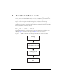
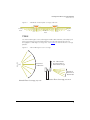
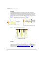
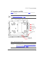
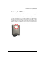
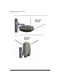
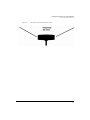
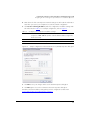
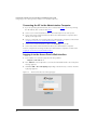
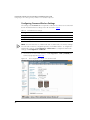
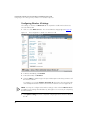
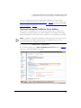
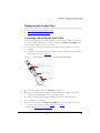
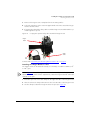
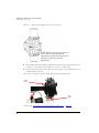
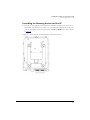
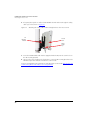
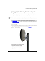
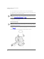
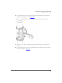
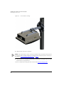
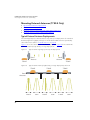
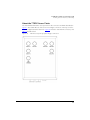

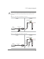
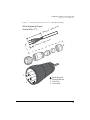
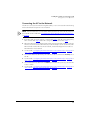
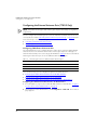
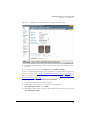
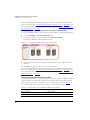
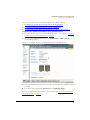
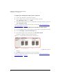
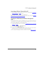

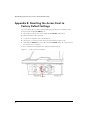
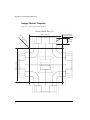
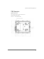
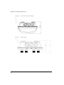
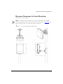
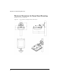
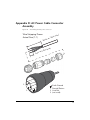
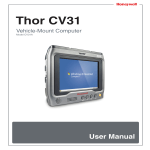

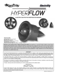
![[ PDF ] 全ページ一括(2.1MB)](http://vs1.manualzilla.com/store/data/006718108_2-517d4f1f4345d16e2d64328e505fdb32-150x150.png)