1
Intel® Server Board SE7501BR2
Product Guide
A Guide for Technically Qualified Assemblers of Intel® Identified
Subassemblies/Products
Order Number: A97020-002
Disclaimer
Information in this document is provided in connection with Intel® products. No license, express or implied, by estoppel or
otherwise, to any intellectual property rights is granted by this document. Except as provided in Intel’s Terms and Conditions
of Sale for such products, Intel assumes no liability whatsoever, and Intel disclaims any express or implied warranty, relating
to sale and/or use of Intel products including liability or warranties relating to fitness for a particular purpose, merchantability,
or infringement of any patent, copyright or other intellectual property right. Intel products are not designed, intended or
authorized for use in any medical, life saving, or life sustaining applications or for any other application in which the failure of
the Intel product could create a situation where personal injury or death may occur. Intel may make changes to
specifications and product descriptions at any time, without notice.
Intel and Xeon are trademarks or registered trademarks of Intel Corporation or its subsidiaries in the United States and other
countries.
† Other names and brands may be claimed as the property of others.
Copyright © 2002, Intel Corporation. All Rights Reserved.
Contents
1 Description.......................................................................................................9
Server Board Features ..........................................................................................................9
Server Board Connector and Component Locations...................................................11
Back Panel Connectors ..............................................................................................12
Intel® Chipset.............................................................................................................12
Processor(s) ...............................................................................................................14
Memory .....................................................................................................................15
PCI I/O Subsystem .....................................................................................................15
Video Controller..........................................................................................................17
Network Interface Controllers (NICs) ..........................................................................18
ACPI
.....................................................................................................................20
Wakeup Events ..........................................................................................................20
System Management ..........................................................................................................21
Baseboard Management Controller ............................................................................21
Field Replaceable Units and Sensor Data Records ....................................................22
System Event Log ......................................................................................................22
Platform Event Management ......................................................................................22
Emergency Management Port ....................................................................................23
Intel® Server Management.........................................................................................24
Security ...............................................................................................................................25
Secure Mode ..............................................................................................................26
Password Protection...................................................................................................27
Intrusion Switch Monitoring.........................................................................................28
Floppy Write Protection ..............................................................................................28
Fixed Disk Boot Sector Write Protect..........................................................................28
Power Switch Mask ....................................................................................................28
2 Server Board Installations and Upgrades...................................................29
Tools and Supplies Needed ................................................................................................29
Before You Begin ................................................................................................................29
Emissions Disclaimer..................................................................................................29
Safety Cautions ..........................................................................................................29
Safety and Regulatory Compliance .....................................................................................30
Minimum Hardware Requirements ......................................................................................31
Installation Notes.................................................................................................................31
Installation Procedures........................................................................................................32
Installing the I/O Gasket and Shield............................................................................32
Installing Chassis Standoffs........................................................................................34
Installing the Rubber Bumper .....................................................................................35
Installing the Server Board .........................................................................................36
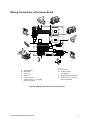
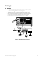
Making Connections to the Server Board....................................................................37
Cable Routing.............................................................................................................38
Installing or Replacing Processor(s) ...........................................................................39
Installing Memory .......................................................................................................52
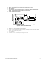
Finishing Up ...............................................................................................................53
Replacing the Back up Battery....................................................................................54
3
3 POST and the BIOS Setup Utility .................................................................57
Power-On Self-Test (POST)................................................................................................57
Temporarily Changing the Boot Device Priority...........................................................57
BIOS Setup .........................................................................................................................58
If BIOS Setup Is Inaccessible .....................................................................................58
Starting Setup.............................................................................................................58
Setup Menus ..............................................................................................................59
Menu Selection Bar ....................................................................................................60
Main Menu..................................................................................................................60
Advanced Menu..........................................................................................................62
Security Menu ............................................................................................................66
Server Menu...............................................................................................................67
Boot Menu ..................................................................................................................71
Exit Menu ...................................................................................................................72
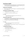
Upgrading the BIOS ............................................................................................................73
Preparing for the Upgrade ..........................................................................................73
Performing the BIOS Upgrade ....................................................................................74
Changing the BIOS Language ....................................................................................75
Hot Keys .............................................................................................................................75
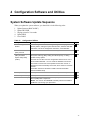
4 Configuration Software and Utilities ...........................................................77
System Software Update Sequence....................................................................................77
Server Configuration Wizard ...............................................................................................78
Direct Platform Control (DPC) Console ...............................................................................79
DPC Console Modes of Operation..............................................................................80
Running the DPC Console..........................................................................................80
Using the System Setup Utility ............................................................................................81
Creating SSU Diskettes ..............................................................................................81
Running the SSU........................................................................................................82
Setting Boot Device Priority ........................................................................................83
Setting Passwords and Security Options ....................................................................83
Viewing the System Event Log ...................................................................................85
Viewing FRU Information............................................................................................85
Viewing Sensor Data Records ....................................................................................86
Updating System Firmware and BIOS ........................................................................86
Managing the Server Remotely ...........................................................................................87
How to Set Up Remote LAN Access...........................................................................87
How to Set Up Remote Modem or Serial Access........................................................89
How to Set Up Paging Alerts ......................................................................................91
How Set Up LAN Alerts ..............................................................................................93
Firmware Update Utility Description ....................................................................................95
How to Run the Firmware Update Utility .....................................................................95
FRU/SDR Load Utility Description .......................................................................................95
How to Use the FRU/SDR Load Utility........................................................................96
Setting a System Asset Tag ................................................................................................98
Creating Diskettes...............................................................................................................98
Installing a Service Partition (Optional)................................................................................99
Saving and Restoring the System Configuration ...............................................................100
Using the Intel Server Management and Intel® SMaRT Tool (Optional) ............................102
4
Intel Server Board SE7501BR2 Product Guide
Installing Intel Server Management...........................................................................103
Installing Intel SMaRT Tool.......................................................................................103
5 Solving Problems ........................................................................................105
Resetting the System ........................................................................................................105
Initial System Startup ........................................................................................................105
Checklist ...................................................................................................................105
Running New Application Software ...................................................................................106
Checklist ...................................................................................................................106
After the System Has Been Running Correctly ..................................................................106
Checklist ...................................................................................................................106
More Problem Solving Procedures ....................................................................................107
Preparing the System for Diagnostic Testing ............................................................107
Monitoring POST ......................................................................................................107
Verifying Proper Operation of Key System Lights .....................................................107
Confirming Loading of the Operating System ...........................................................107
Specific Problems and Corrective Actions .........................................................................108
Power Light Does Not Light ......................................................................................108
No Characters Appear on Screen.............................................................................108
Characters Are Distorted or Incorrect .......................................................................109
System Cooling Fans Do Not Rotate Properly ..........................................................109
Diskette Drive Activity Light Does Not Light ..............................................................110
Hard Disk Drive Activity Light Does Not Light ...........................................................110
CD-ROM Drive Activity Light Does Not Light ............................................................110
Cannot Connect to a Server .....................................................................................110
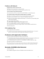
Problems with Network .............................................................................................111
PCI Installation Tips..................................................................................................111
Problems with Application Software ..................................................................................111
Bootable CD-ROM Is Not Detected ...................................................................................111
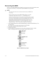
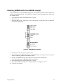
Recovering the BIOS.........................................................................................................112
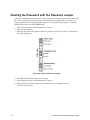
Clearing the Password with the Password Jumper............................................................114
Clearing CMOS with the CMOS Jumper............................................................................115
6 Getting Help .................................................................................................117
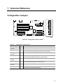
7 Technical Reference ...................................................................................119
Configuration Jumpers ......................................................................................................119
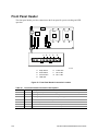
Front Panel Header ...........................................................................................................120
8 Regulatory and Integration Information....................................................121
Product Regulatory Compliance ........................................................................................121
Product Safety Compliance ......................................................................................121
Product EMC Compliance ........................................................................................121
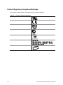
Product Regulatory Compliance Markings ................................................................122
Electromagnetic Compatibility Notices ..............................................................................123
FCC (USA) ...............................................................................................................123
Industry Canada (ICES-003).....................................................................................124
Europe (CE Declaration of Conformity).....................................................................124
Taiwan Declaration of Conformity.............................................................................124
Korean RRL Compliance ..........................................................................................124
Contents
5
Australia / New Zealand............................................................................................124
Index ..................................................................................................................125
Figures
Figure 1. Server Board Connector and Component Locations............................................11
Figure 2. Back Panel Connectors .......................................................................................12
Figure 3. Attaching the Gasket to the I/O Shield.................................................................32
Figure 4. Attaching the Label to the I/O Shield ...................................................................33
Figure 5. Installing the I/O Shield........................................................................................33
Figure 6. Configuring Chassis Standoffs ............................................................................34
Figure 7. Installing the Rubber Bumper ..............................................................................35
Figure 8. Attaching the Server Board .................................................................................36
Figure 9. Making Connections to the Server Board ............................................................37
Figure 10. Routing the SCSI and Floppy Drive Cable.........................................................38
Figure 11. Opening Socket Lever and Attaching Processor................................................40
Figure 12. Attaching Retention Mechanism ........................................................................41
Figure 13. Applying Thermal Grease..................................................................................41
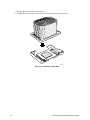
Figure 14. Attaching the Heat Sink and Retention Clip .......................................................42
Figure 15. Attaching the Wind Tunnel Fan .........................................................................43
Figure 16. Attaching the Heat Sink Fan to the Top of the PWT ..........................................44
Figure 17. Attaching the Top Assembly to the Retention Mechanism .................................45
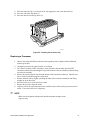
Figure 18. Processor and Wind Tunnel Installed ................................................................46
Figure 19. Installing the Processor Retention Brackets ......................................................47
Figure 20. Raising the Locking Bar.....................................................................................48
Figure 21. Installing Processors .........................................................................................48
Figure 22. Lower Locking Bar.............................................................................................49
Figure 23. Applying Thermal Grease..................................................................................49
Figure 24. Installing the Heat Sink......................................................................................50
Figure 25. Installing the Heat Sink Clip...............................................................................51
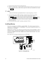
Figure 26. Installing Memory ..............................................................................................52
Figure 27. Making Back Panel Connections .......................................................................53
Figure 28. Replacing the Backup Battery ...........................................................................55
Figure 29. BIOS Recovery Jumper...................................................................................112
Figure 30. Password Recovery Jumper............................................................................114
Figure 31. CMOS Recovery Jumper.................................................................................115
Figure 32. Configuration Jumper Location........................................................................119
Figure 33. Front Panel Header Connection Location ........................................................120
6
Intel Server Board SE7501BR2 Product Guide
Tables
Table 1.
Table 2.
Table 3.
Table 4.
Table 5.
Table 6.
Table 7.
Table 8.
Table 9.
Table 10.
Table 11.
Table 12.
Table 13.
Table 14.
Table 15.
Table 16.
Table 17.
Table 18.
Table 19.
Table 20.
Table 21.
Table 22.
Table 23.
Table 24.
Table 25.
Table 26.
Table 27.
Table 28.
Table 29.
Table 30.
Table 31.
Table 32.
Table 33.
Table 34.
Table 35.
Contents
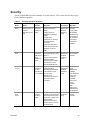
Server Board Features ...................................................................................9
64-bit PCI Segment Configuration................................................................15
10/100 Megabit LEDs (NIC1) .......................................................................19
Gigabit LEDs (NIC2) ....................................................................................19
Security Operation Summary .......................................................................25
Keyboard Commands...................................................................................59
On-Screen Options ......................................................................................60
Menu Selection Bar......................................................................................60
Main Menu Selections ..................................................................................60
Primary/Secondary, Master/Slave Submenu ................................................61
Processor Settings Submenu .......................................................................62
Advanced Menu ...........................................................................................62
PCI Configuration Submenu.........................................................................63
PCI Configuration, Embedded Devices Submenu ........................................63
Peripheral Configuration Submenu...............................................................64
Memory Configuration Submenu..................................................................65
Advanced Chipset Control Submenu............................................................65
Security Menu ..............................................................................................66
Server Menu ................................................................................................67
System Management Submenu ...................................................................68
Console Redirection Submenu.....................................................................69
Event Log Configuration Submenu...............................................................70
Fault Resilient Booting Submenu .................................................................70
Boot Menu....................................................................................................71
Boot Device Priority Submenu......................................................................71
Hard Drive Selection Submenu ....................................................................71
Removable Devices Submenu .....................................................................72
ATAPI CD-ROM Devices Submenu .............................................................72
Exit Menu .....................................................................................................72
Hot Keys ......................................................................................................75
Configuration Utilities ...................................................................................77
Command Line Format.................................................................................97
Configuration Jumper (J1H1) .....................................................................119
Front Panel Header Connection Descriptions.............................................120
Product Certification Markings....................................................................122
7
8
Intel Server Board SE7501BR2 Product Guide
1 Description
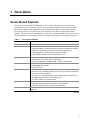
Server Board Features
The Intel® Server Board SE7501BR2 offers a “flat” design, with the processors and memory
subsystems residing on the board. The server board supports dual-processor operation with the
Intel® E7501 chipset and the Intel® Xeon™ processors with 512KB L2 Cache in the Flip-chipmicro Pin Grid Array2 (FC-mPGA2) or in the Interposer micro Pin Grid Array (INT-mPGA)
package. The board contains embedded devices for video, network, and IDE, and it provides basic
monitoring hardware and interrupt control for dual-processors and PC/AT compatible operation.
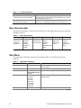
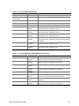
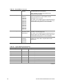
Table 1.
Server Board Features
Feature
Description
Processor
Dual 533 or 400 FSB Intel® Xeon™ processors with 512KB L2 Cache
Chipset
Intel chipset:
• Supports 533 MHz Front Side Bus (FSB), backwards compatible with 400 MHz
• Intel® E7501 Chipset Memory Controller Hub (MCH) (North Bridge)
• Intel® 82801CA I/O Controller Hub3 (ICH3) (South Bridge)
• Intel® 82870P2 PCI/PCI-X 64-bit Hub2 (P64H2) I/O hub
Memory
• Registered DDR266 compliant ECC DIMMs providing up to 8 GB of memory
• DIMM Sockets: Four 72-bit, 184-pin, gold contact
• Supported DIMM sizes: 128 MB, 256 MB, 512 MB, 1 GB, and 2 GB
Video
• Integrated onboard ATI Rage† XL 64-bit SVGA video controller
• 8 MB SDRAM video memory
• SVGA video port
PCI bus
Six PCI expansion slots support full or half-length boards:
• Two 64-bit, PCI-X 100 MHz expansion slots. This segment will run at 133 MHz
when only one slot is populated
• Two 64-bit, PCI-X 100 MHz expansion slots. Modular RAID on motherboard
(M-ROMB) support provided via one of these slots.
• Two 32-bit, 33 MHz, PCI expansion slots
Network
Dual integrated on-board Ethernet connections:
• Intel® PRO 10/100 Fast Ethernet Controller (Intel® 82550PM)
• Intel® PRO Gigabit Ethernet Controller (Intel® 82540EM)
Integrated SCSI
Adaptec† AIC-7901 single-channel U320 SCSI controller (Single ended mode not
supported)
continued
9
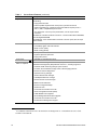
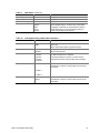
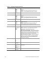
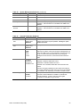
Table 1.
Server Board Features (continued)
Feature
Description
System I/O
National Semiconductor† PC87417 Super I/O Controller (LPC bus) that provides
the following:
• Floppy Disk Controller
• PS/2-compatible keyboard and mouse ports, 6-pin DIN connectors
• Advanced parallel port, supporting Enhanced Parallel Port (EPP) level 1.7
and 1.9, ECP, compatible 25-pin connector
• Two serial ports: One a-synch 9-pin RS-232C, one via 10-pin internal
connector
Two Ethernet controllers via RJ45 connectors: one Intel Fast Ethernet 82550PM,
one Intel Gigabit 82540EM
Five USB ports: three stacked USB connectors in I/O rear panel, two via 10-pin
internal header
• SSI-EEB 3.0 compliant
Power
• Power/Sleep Switch with LED Indicator
• Wake on LAN† (WOL)
• Wake on Ring (WOR)
• BIOS password
Security
• Keyboard password protection
• Floppy write-protect
• SSI-EEB 3.0 compliant form factor
Form Factor
Server Management
IPMI 1.5 compliant
1
Intel® Baseboard Management Controller (BMC)
Intel® Server Management (ISM) software Version 5.5, including support for:
• Hardware health monitoring through system sensors
• Proactive, alert notification through email, LAN and paging devices
• Remote access and diagnostics
• System Event Log manager
• Sensor Data Records manager
• Field Replaceable Unit manager
• Remote Sensor Access manager
• BIOS Console redirection
• Remote Configuration/Setup
• Serial over LAN
• Command Line Interface over LAN
• Server Configuration Wizard (SCW)
• Intel® SMaRT Tool Integration
• Online Rolling BIOS & Firmware Upgrade
• Command Line Interface over LAN
• ID LED Server Management Support
1
For additional information refer to the Intel® Server Management ver 5.5 Installation & User’s Guide
available on the ISM CD.
10
Intel Server Board SE7501BR2 Product Guide
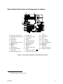
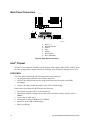
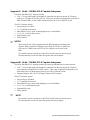
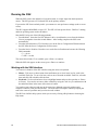
Server Board Connector and Component Locations
GG
II
HH
JJ
KK
A
FF
EE
DD
BB CC
AA
Z
B
C
D
E
F
G H
I
J
K
L
M
N
Y
X
W
V
T
U S
R
Q
P
O
OM15026
A
B
C
D
E
F
G
H
I
J
K
L
M
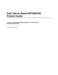
Primary Processor (CPU1)
Secondary Processor (CPU2)
CPU Power
System Fan 6
System Fan 5
Floppy Disk Drive Connector
IPMB Connector
HSBP B
HSBP A
USB Connector
Primary IDE (ATA 100)
System Fan 4
Secondary IDE (ATA 100)
N
O
P
Q
R
S
T
U
V
W
X
Y
Z
System Fan 3
Front Panel Connector
Jumper Block
Battery
LVD SCSI Connector
HDD LED Connector
Chassis Intrusion
EMP in Use
Serial B
32/33 PCI, Slots 5 & 6
ICMB
2
64/100 PCI-X, Slots 3 & 4
64/100 PCI-X, Slots 1 & 2
AA
BB
CC
DD
EE
FF
GG
HH
II
JJ
KK
System Fan 1
System Fan 2
ID LED
NIC 1 (10/100)
NIC 2 (1 gigabit)
System I/O Connectors
DIMM Sockets
Aux Power
Main Power
CPU1 Fan Connector
CPU2 Fan Connector
Figure 1. Server Board Connector and Component Locations
2
M-ROMB support provided via Slot4
Description
11
DIMM Memory Connect
DIMM Memory Connect
DIMM Memory Connect
DIMM Memory Connect
Main Power
Aux. Pwr
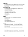
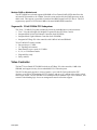
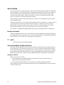
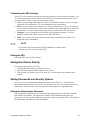
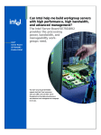
Back Panel Connectors
USB
E
A
B
C
D
F
G
OM14663
A.
B.
C.
D.
E.
F.
G.
USB 1, 2, 3
Keyboard / Mouse
Serial A
Video
Parallel
NIC2 (Gigabit)
NIC1 (10/100 Mb)
Figure 2. Back Panel Connectors
Intel® Chipset
The Intel® Server Board SE7501BR2 includes the Intel E7501 chipset (MCH, ICH3, P64H2), which
provides an integrated I/O bridge and memory controller, and a flexible I/O subsystem core (PCI).
E7501 MCH
The E7501 MCH North Bridge (MCH) integrates three main functions:
• An integrated high performance main memory subsystem
• An HI 2.0 bus interface that provides a high-performance data flow path to the P64H2
(I/O Bridge)
• An HI 1.5 bus that provides an interface to the ICH3-S (South Bridge)
Other features provided by the MCH include the following:
•
•
•
•
•
•
12
Full support of registered ECC on the memory bus
Full support of Intel® x4 Single Device Data Correction on the memory interface with x4
DIMMs
Twelve deep in-order queue
Full support of registered DDR266 ECC DIMMs
Support for up to 8 GB of DDR memory
Memory scrubbing
Intel Server Board SE7501BR2 Product Guide
P64H2 I/O Hub
The primary role of the P64H2 is to provide an integrated I/O bridge to the 64-bit PCI-X segments.
This subsystem supports two independent 64-bit PCI-X segments, each with two 64-bit/100MHz
PCI-X slots. The Adaptec AIC-7901 embedded controller is enabled via one of the PCI-X
segments of the P64H2.
ICH3 I/O Controller Hub
The primary role of the ICH3 is to provide the gateway to all PC-compatible I/O devices and
features. The SE7501BR2 uses the following ICH3 features:
• 32-bit/33 MHz PCI bus interface
• Low Pin Count (LPC) bus interface
• IDE interface, with Ultra DMA 100 capability
• Universal Serial Bus (USB) interface
• PC-compatible timer/counter and DMA controllers
• APIC and 8259 interrupt controller
• Power management
• General purpose I/O
• System RTC
Super I/O
The National Semiconductor† PC87417 Super I/O Plug-and-Play Compatible with
ACPI-Compliant Controller/Extender is used on the SE7501BR2 server board. This device
provides the system with:
• Two serial ports
• One parallel port
• Floppy disk controller (FDC)
• PS/2†-compatible keyboard and mouse controller
• Wake event control
Serial Ports
One DB9 connector is provided on the back panel for the Serial A port. The Serial A port is
compatible with 16550A and 16450 modes. This port can be set to one of four different
COM ports, each of which can be enabled separately. When enabled, each port can be programmed
to generate edge- or level-sensitive interrupts. When disabled, the serial port interrupts are
available for add-in cards.
A DH10 10-pin serial header is available on the baseboard for an optional Serial B port. The
Serial B port can be used as an Emergency Management Port.
Parallel Port
The SE7501BR2 baseboard provides a 25-pin parallel port back panel connector. The Super I/O
provides an IEEE 1284-compliant 25-pin bi-directional parallel port. BIOS programming of the
Super I/O registers enables the parallel port and determines the port address and interrupt. When
disabled, the interrupt is available to add-in cards.
Description
13
Floppy Disk Connector
The floppy disk connector on the server board provides the interface to the floppy disk drive from
the floppy disk controller.
Keyboard and Mouse Connectors
The separate keyboard and mouse connectors, found on the back panel of the server board, are
PS/2-compatible. The keyboard and mouse connectors are interchangeable.
Processor(s)
The Intel® Server Board SE7501BR2 accommodates one or two Intel Xeon processors with 512KB
L2 Cache via two SKT604 604-pin zero-insertion force (ZIF) sockets. The processors interface
with the system bus at 533 MHz, backwards compatible with 400 MHz. When only one processor
is installed, it should be in the socket labeled CPU1 and the other socket must be empty.
For a complete list of supported processors, see:
http://support.intel.com/support/motherboards/server/SE7501BR2
Dual Processor Operation
The Intel Xeon processor interface is dual-processor (DP)-ready. The processor subsystem
includes a single VR (Voltage Regulator) to support both processors. Interrupt generation and
notification for the processors is done by the Advanced Programmable Interrupt Controllers
(APICs) in the ICH3 and P64H2. When two processors are installed, both processors must be of
identical revision, core voltage, and bus/core speeds.
Boxed Processor Fan Heat Sink
Complete thermal solution including a processor wind tunnel (PWT), fan, and heatsink is supplied
with each boxed Intel Xeon processor.
✏
NOTE
Do not install the Processor Wind Tunnel when using the Intel® Server Chassis
SC5200 with hot swap redundant power. To install the heat sink you must use
the Retention Mechanisms supplied with the SC5200 chassis. For this chassis,
see the installation instructions beginning on page 47.
Otherwise, install the processor wind tunnels according to the instructions
provided in this document or in the SE7501BR2 Quick Start User’s Guide. These
instructions are different than those included with the boxed processor. For
proper processor cooling, the fan inlet air temperature should be below 45 °C.
CAUTION
Clearance is required at each end of the fan heat sink to ensure unimpeded
airflow for proper cooling. Restricting the airflow through the processor heat
sink can cause overheating and subsequent failure of the processor.
14
Intel Server Board SE7501BR2 Product Guide
Memory
The Intel® Server Board SE7501BR2 contains four 184-pin DIMM sockets and provides support
for up to 8 GB of DDR266 memory. The memory subsystem provides dual memory bus
architecture; the memory on the board is partitioned into two banks of DDR DIMMs. DIMMs must
be installed in pairs, providing a 144-bit wide data path via two separate memory buses.
The server board supports up to four ECC DDR DIMMs that are compliant with the JEDEC
DDR266 specification. A wide range of DIMM sizes are supported, including:
• 128 MB
• 256 MB
• 512 MB
• 1 GB
• 2 GB
The minimum supported memory configuration is 256 MB, using two 128 MB DIMMs. The
maximum configurable memory size is 8 GB using four 2 GB DIMMs.
✏
NOTE
DIMMs must be installed in pairs and must be populated by bank starting
with DIMM 1A and 1B (contiguous sockets). Although the SE7501BR2
server board architecture allows the user to mix various sizes of DIMMs
between banks, DIMMs must be identical within the banks. For a list of
tested memory, see:
http://support.intel.com/support/motherboards/server/SE7501BR2
PCI I/O Subsystem
The SE7501BR2 server board provides three PCI bus segments:
• Segment C with two PCI-X 64-bit / 100 MHz slots (Slot 1 and 2)3
• Segment B with two PCI-X 64-bit / 100 MHz slots (Slot 3 and 4)4
• Segment A with two PCI 32-bit / 33 MHz slots (Slot 5 and 6)
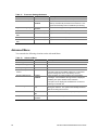
The following table outlines the capabilities of each 64-bit bus segment. The least capable card
installed on that bus determines the bus mode/speed. In other words, the bus will run at the speed
of the slowest installed card.
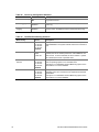
Table 2.
3
4
64-bit PCI Segment Configuration
# of slots populated per segment
Segment B (mode, speed)
Segment C (mode, speed)
0
PCI-X, 100 MHz
PCI-X, 133 MHz
1
PCI-X, 100 MHz
PCI-X, 133 MHz
2
PCI-X, 100 MHz
PCI-X, 100 MHz
This segment will operate at 133 MHz when only one slot is populated.
Modular RAID on Motherboard (M-ROMB) support is provided via Slot 4.
Description
15
Segment C: 64-bit / 100 MHz PCI-X Capable Subsystem
The 64-bit/100 MHz PCI-X segment includes:
• Two 3.3 V keyed full-length, full height PCI expansion slots that can support PCI-X add in
cards up to 133 MHz (PCI-X Slots1 and 2). These slots are backward compatible to 64-bit/100
MHz, 64-bit/66 MHz, 64-bit/33 MHz, and universal keyed 32-bit/33 MHz PCI cards.
The PCI-X features include:
• Bus speed up to 133 MHz
• 3.3 V signaling environment
• Burst transfers up to a peak of 1000 Megabytes per second (MB/s)
• 8-, 16-, 32-, or 64- bit data transfers
• Plug-and-Play ready
• Parity enabled
✏
NOTES
Speed on the PCI-X will be programmed by the BIOS according to loading on the
segment. When a segment is configured with a single PCI-X 64/133 card the bus
will work at 133 MHz; with two PCI-X 64/133 cards the bus will work at 100
MHz.
If you install a slower card into one of the PCI-X 64/100 connectors, the bus speed
for both connectors will be lowered to the speed of the slowest adapter.
Segment B: 64-bit / 100 MHz PCI-X Capable Subsystem
The 64-bit/100 MHz PCI-X segment includes the following embedded device and connectors:
• Two 3.3 V keyed full-length, full height PCI expansion slots that can support PCI-X add in
cards running at 100 MHz (PCI-X Slots 3 and 4). These slots are backward compatible to 64bit/66 MHz, 64-bit/33 MHz and universal keyed 32-bit/33 MHz PCI cards.
• Integrated Adaptec AIC-7901 U320 Single Channel SCSI Controller
The PCI-X features include:
•
•
•
•
•
•
✏
Bus speed up to 100 MHz
3.3 V signaling environment
Burst transfers up to a peak of 800 Megabytes per second (MB/s)
8-, 16-, 32-, or 64-bit data transfers
Plug-and-Play ready
Parity enabled
NOTE
If you install a slower card into one of the PCI-X 64/100 connectors, the bus speed
for both connectors will be lowered to the speed of the slowest adapter.
16
Intel Server Board SE7501BR2 Product Guide
Modular RAID on Motherboard
The SE7501BR2 server board supports M-ROMB or Zero Channel RAID (ZCR) that allows the
on-board SCSI controller to be “hidden” from the system and used by the RAID processor on the
add-in card. This support is provided via hardware and BIOS support on PCI-X Slot 4. This PCI
segment may operate as PCI 64-bit/66 MHz with some ROMB RAID controllers.
Segment A: 32-bit/33 MHz PCI Subsystem
The 32-bit / 33 MHz PCI segment includes the following embedded devices and connectors:
• Two 5 V keyed full-length, full height PCI expansion slots (PCI Slots 5 and 6)
• Integrated Intel 10/100 Fast Ethernet Controller (Intel 82550PM)
• Integrated Intel Gigabit Ethernet Controller (Intel 82540EM)
• Integrated ATI Rage XL video controller with 8 MB of on-board SDRAM
32-bit/33 MHz PCI features include:
• Bus speed up to 33 MHz
• 5 V signaling environment
• Burst transfers up to a peak of 132 MB/s
• 8-, 16-, or 32-bit data transfers
• Plug-and-Play ready
• Parity enabled
Video Controller
The Intel® Server Board SE7501BR2 includes an ATI Rage XL video controller, 8 MB video
SDRAM, and support circuitry for an embedded SVGA video subsystem.
The SVGA subsystem supports a variety of modes: up to 1600 X 1200 resolution for CRT
displays, up to 1024 x 768 resolution for TFT displays, and up to 16.7 million colors with a refresh
rate of up to 100Hz. The SE7501BR2 server board provides a standard 15-pin VGA connector, and
external video blanking logic for server management console redirection support.
Description
17
Network Interface Controllers (NICs)
The Intel® Server Board SE7501BR2 includes one 10/100Base-TX network connection, based on
the Intel 82550PM Fast Ethernet Controller (NIC1)5, and one 10/100/1000Base-TX network
connection, based on Intel 82540EM Gigabit Ethernet Controller (NIC2). Facing the rear of the
system, the gigabit controller is on the left, next to the video connector.
You can disable the embedded NICs in BIOS Setup Utility. When disabled, the controller(s) are
not visible to the operating system.
✏
NOTE
To ensure EMC (Electromagnetic Compatibility) product regulation
compliance, the system must be used with a shielded LAN cable.
Supported Network Features
The SE7501BR2 supports the following features of the 82550PM and 82540EM controllers:
• Glueless 32-bit PCI Bus Master Interface (Direct Drive of Bus), compatible with PCI Bus
Specification, revision 2.1 / 2.2
• Chained memory structure, with improved dynamic transmit chaining for enhanced
performance
• Programmable transmit threshold for improved bus utilization
• Early receive interrupt for concurrent processing of receive data
• On-chip counters for network management
• Autodetect and autoswitching for 10 or 100 MB/s network speeds (82550 only)
• Support for 10 Mb/s, 100 Mb/s, and 1000 Mb/s networks, full or half duplex-capable, with
back-to-back transmit at 100 MB/s
• Integrated physical interface to TX magnetics
• The magnetics component terminates the 100Base-TX connector interface. A flash device
stores the network ID
• Support for Wake on LAN (WOL)
• Advanced Networking Service Features (Teaming, Load balancing)
5
18
NIC1 is the designated Intel Server Management NIC.
Intel Server Board SE7501BR2 Product Guide
NIC Connector and Status LEDs
The Intel® Server Board SE7501BR2 supports two RJ45 connectors, one for the 10/100-Megabit
Fast Ethernet controller (NIC1), and the other for the Gigabit Ethernet controller (NIC2).
NIC1 drives two LEDs on its RJ45 connector. These LEDs indicate link/activity on the LAN and
the speed of operation. This connector is on the right side when looking at the I/O area at the back
of the board. The green LED to the right of the connector indicates a network connection is in
place when it is on and transmit/receive activity when it is blinking. The green LED to the left of
the connector indicates 10 Mbps operation when it is off and100 Mbps operation when it is lit and.
See the following table for an overview.
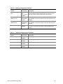
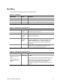
Table 3.
10/100 Megabit LEDs (NIC1)
LED Color
Green (left)
Green (right)
LED State
NIC1 State
Off
10-Mbps
On
100-Mbps
On
On
Blinking
Transmit / Receive activity
NIC2 drives two LEDs located on its RJ45 connector; this connector is on left side when looking at
the I/O area in the back of the board. The green LED to the right of the connector indicates a
network connection is in place when it is on, and transmit/receive activity when it is blinking. The
bi-color LED to the left of the connector indicates 10-Mbps when it is off, 100-Mbps operation
when it is green, and 1000-Mbps operation when it is yellow. See the following table for an
overview.
Table 4.
Gigabit LEDs (NIC2)
LED Color
Green/Yellow (left)
Green (right)
Description
LED State
NIC2 State
Off
10-Mbps
Green
100-Mbps
Yellow
1000-Mbps
On
On
Blinking
Transmit / Receive activity
19
ACPI
By using Advanced Configuration and Power Interface (ACPI), an ACPI-aware operating system
can place the system into a state in which the hard drives spin-down, the system fans stop, and all
processing is halted. In this state the power supply is still on and the processors still dissipate some
power, so the power supply fan and processor fans are still running.
✏
NOTE
ACPI requires an operating system that supports this feature.
The server board supports sleep states S0, S1, S4, and S5. When the server board is operating in
ACPI mode, the operating system retains control of the system and the OS policy determines the
entry methods and wake-up sources for each sleep state – sleep entry and wake-up event
capabilities are provided by the hardware but are enabled by the operating system.
•
•
•
•
S0: Normal running state.
S1: DC Power remains on. The operating system saves the context and enters a low-power
state. The system can wake from the S1 state using a PS/2 keyboard, mouse, or USB device,
by pressing the power button press, or from a wakeup event.
S4: Hibernate or Save to Disk. The memory and machine state are saved to disk. Pressing the
power button or another wakeup event restores the system state from the disk and resumes
normal operation. This assumes that no hardware changes were made to the system while it
was off.
S5: Soft off. Only the RTC section of the chip set is running in this state.
CAUTION
The system is off only when the AC power is disconnected.
Wakeup Events
The SE7501BR2 system supports several wakeup events.
Wake on LAN
Wake on LAN allows system power to be activated through the network. If the system is in the S1
or S4 state, it can be turned on remotely by sending a specific packet to the remote system. The
system contains a configuration option that allows the on-board NICs to be enabled to wake the
system from a S4 or S5 sleep state, even if the operating system disabled Wake on LAN when it
powered down the system. This provides an option for users who want to use standard, but
non-secure, Wake on LAN capability for operations such as after-hours maintenance. Server
management features provide a secure system power-up, plus the ability to provide BIOS boot
option.
20
Intel Server Board SE7501BR2 Product Guide
Wake on Ring
Wake on Ring allows system power to be activated through the serial ports when this option is
enabled in Setup. If the system is in the S1 or S4 state, it can be turned on remotely by the Ring
Indicate RI signals from the serial ports.
✏
NOTE
Wake on Ring is disabled in Serial B if this port is enabled as a server
management port.
Wake on RTC Alarm
Wake on RTC alarm allows system power to be activated through a real-time clock alarm when this
option is enabled in Setup. If the system is in the S1 or S4 state, it can be turned on by an RTC
trigger event.
System Management
Intel integrates system management features into the hardware and provides additional features
through Intel® Server Management (ISM) software version 5.5. A brief description of the features
is provided below. For instructions on using the features described, refer to the Configuration
Software and Utilities chapter, beginning on page 77.
Baseboard Management Controller
Intel server boards incorporate a baseboard management controller (BMC), which is a dedicated
microcontroller for system management activities. The BMC performs the following functions:
• Monitors system components and sensors, including processors, memory, fans, power supplies,
temperature sensors, and chassis intrusion sensors.
• Manages nonvolatile storage for the system event log (SEL), sensor data records (SDRs), and
baseboard field-replaceable unit (FRU) inventory.
• Interfaces with the emergency management port (EMP) and LAN1 port to send alerts and
interact with remote management systems.
• Provides the main front panel control functions (power on/off, reset, and so on).
Description
21
Field Replaceable Units and Sensor Data Records
Field replaceable units (FRUs) are major modules in the chassis that contain active electronic
circuitry. FRUs can store information-such as board serial number, part number, name, and asset
tag-that can be read using the System Setup Utility. The BMC stores FRU information for the
baseboard in a nonvolatile storage component on the board.
The BMC uses Sensor Data Records (SDRs) to identify the sensors in the system for monitoring.
SDRs provide a list of the sensors, their characteristics, location, type, and type-specific
information, such as default threshold values, factors for converting a sensor reading into the
appropriate units (mV, rpm, degrees Celsius), and information on the types of events that a sensor
can generate. The BMC stores SDR information in a nonvolatile storage component on the
baseboard.
You can use the FRU/SDR Load Utility to initialize or update the FRU and SDR information.
Intel® server boards are shipped from the factory with some sensors disabled because the actual
configuration of the chassis is only determined when the user completes the system configuration.
For example, chassis-specific FRU information, such as chassis part number, must be configured
when the system is configured. For these reasons, it is important to run the FRU/SDR Load Utility
as part of the system setup process. You should also run the FRU/SDR Load Utility whenever you
change the number of fans, processors, or power supplies in the server.
System Event Log
The BMC manages a system event log (SEL), where it records significant or critical system events.
These events include temperatures and voltages out of range, fan failures, and other sensor-related
events. The BIOS, software, and other devices can also log events by sending messages to the
BMC. The SEL is stored in nonvolatile storage.
You can view the current contents of the SEL by using the System Setup Utility.
Platform Event Management
Events can trigger alerts and other actions by the BMC. The server is configured with the
following set of standard events:
• Temperature sensor out of range
• Voltage sensor out of range
• Fan failure
• Chassis intrusion
• Power supply failure
• Memory error
• POST error
• Processor fault resilient booting (FRB) failure
• Fatal nonmaskable interrupt (NMI) from a source other than the front panel switch
• Watchdog timer reset, power down, or power cycle
• System restart (reboot)
22
Intel Server Board SE7501BR2 Product Guide
Alerts can take either of these forms:
• Platform Event Pages – the BMC dials a paging service and sends a predefined paging string.
To use platform event paging (PEP), you must attach an external modem to the emergency
management port (Serial B). Use the Server Configuration Wizard to configure the pager and
emergency management port information.
• BMC LAN alerts – the BMC sends an alert to a predefined destination on the LAN.
You can configure PEP and BMC LAN alerts by using the Server Configuration Wizard or the
System Setup Utility.
Emergency Management Port
The emergency management port (EMP) refers to the use of the Serial B port, with either an
external modem or direct serial connection, for remote management. The BMC controls the port
and interfaces with remote access software, such as the Direct Platform Control or the Client
System Setup Utility applications in Intel Server Management.
You can configure the EMP by using the Server Configuration Wizard or the System Setup Utility.
EMP and Serial Over LAN
The Serial B port 10-pin header on the board can be configured in several different ways: as a
standard serial port, as an Emergency Management Port, or for serial output redirection over a
LAN. You can configure these settings using either the System Setup Utility or the Server
Configuration Wizard.
✏✏
NOTES
SC5200 Server Chassis considerations: If you have configured the Serial
B port for use as an emergency management port and set it to be “always
available”, the Serial B port will be accessible only by remote server
management software. The operating system will never be able to access the
port.
If you have configured the Serial B port for Serial Over LAN, the port’s
functionality will be impacted only when there is an active Serial Over LAN
session from a remote console. At all other times either the operating system
or the EMP will control the port, depending on your configuration.
Description
23
Intel® Server Management
Intel Server Management (ISM) version 5.5 is a system management package that is included on
the ISM CD. ISM applications interact with the integrated hardware system management features
of the server to allow you to monitor and manage a server. Version 5.5 provides integrated in-band
(operating system up) and out-of-band (operating system down) remote management, event alerting
and logging, including e-mail notification, and proactive fault management. Some of the features
provided are:
• The ability to connect to the server from a Windows†-based client workstation over a LAN
over a modem, or over a direct serial connection to the server, permitting you to manage the
server from a remote location.
• Real-time monitoring and alerting for server hardware sensors.
• Emergency management when the server is off (but still connected to AC power) lets you
verify the state of the server, diagnose hardware problems, and power on/off or reset the server.
• The ability to run the Client System Setup Utility to change the configuration of the managed
server.
ISM can use an optional service partition on the managed server. The service partition is a special
disk partition on the system drive that contains a ROM-DOS† operating system and DOS-based
utilities, including the System Setup Utility, FRU/SDR Load Utility, and other diagnostics
packages you might choose to install. The server can be booted to the service partition, either
locally or remotely, to provide access to the utilities.
The service partition must be installed before the operating system is installed. Instructions for
creating a service partition are available on the Quick Start Users guide.
For more information on Intel Server Management and the individual ISM applications, see the
Intel Server Management Installation and User’s Guide on the ISM CD.
24
Intel Server Board SE7501BR2 Product Guide
Security
The SE7501BR2 BIOS provides a number of security features. This section describes the security
features and their operation.
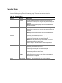
Table 5.
Security Operation Summary
Entry Method/
Event
Entry
Criteria
Secure
Mode
Keyboard
inactivity timer or
runtime
activation of hot
key
User
password
enabled in
Setup
Secure
Boot
Power On/Reset
User
password
and Secure
Boot
enabled in
Setup
Password
on boot
Power On/Reset
Fixed disk
boot
sector
Power On/Reset
Mode
Description
Behavior
Exit Criteria
After Exit
On-board video goes
blank if selected in
Setup.
Floppy writes are
disabled if selected in
Setup.
Except for the
password, no mouse or
keyboard input is
accepted.
Keyboard LEDs flash
Front panel buttons are
disabled, except for
NMI.
User is prompted for
password if booting from
drive A.
System enters Secure
Mode just before
scanning option ROMs.
See above for other
Secure Mode behavior.
User or
administrator
password
followed by
[Enter]
Video is
restored.
Floppy writes
are enabled.
Keyboard and
mouse inputs
are accepted.
Front panel
buttons are
enabled.
User or
administrator
password
followed by
[Enter]
See above for
Secure Mode
behavior.
User
password
set and
password on
boot enabled
System halts for User
Password before
scanning option ROMs.
The system is not in
secure mode.
Except for the
password, no mouse or
keyboard input is
accepted.
User or
administrator
password
followed by
[Enter]
Power and
Reset
switches are
enabled.
PS/2 keyboard
and mouse
inputs are
accepted.
The system
boots
normally.
Boot
sequence is
determined by
setup options.
Set feature
to Write
Protect in
Setup
Write protects the
master record of the IDE
hard drives if the system
boots from a floppy. The
BIOS will also
write-protect the boot
sector of the C: drive if it
is an IDE drive.
Set feature
to Normal in
Setup
Hard drive will
behave
normally.
25
Secure Mode
Secure mode refers to a system state where many of the external inputs and outputs are disabled to
prevent tampering. These include PS/2 ports, floppy and on-board video. When secure mode is in
effect, you must enter a password before the system will accept any keyboard or mouse input,
except for the password entry. When secure mode is in effect, you cannot turn off the system
power or reset the server from the front panel switches.
Secure mode has no effect on functions enabled via remote server management or power control
via the watchdog timer.
Taking the system out of secure mode does not change the state of system power. In other words, if
you press and release the power button while secure mode is in effect, the system will not be
powered down when secure mode is later removed. However, if the front panel power button
remains depressed while secure mode is removed, the server will be powered off.
Secure mode is configured through the BIOS setup options or through the System Setup Utility.
Hot Key Activation
A hot key combination allows the user to activate secure mode immediately instead of waiting for
the configured inactivity time-out to expire. The hot key combination is configured through Setup.
Either Ctrl-Alt-L or Ctrl-Alt-Z can be configured as valid hot keys.
✏
NOTE
Hot keys work only with PS/2 keyboards.
Secure Boot Mode (Unattended Start)
The Secure Boot mode allows the system to boot and run the operating system without requiring
the user password, even if the user password is set. However, until the user password is entered,
mouse and keyboard input is not accepted (except for password entry). If Secure Boot is enabled,
secure mode is enabled shortly before boot. To prevent unauthorized tampering with any option
ROM based setup utilities, enable the “Option ROM Menu Mask” setting in the security menu.
Using Secure Boot
When secure mode is in effect:
• You can boot the server and the operating system will run, but you must enter the user
password to use the keyboard or mouse.
• You cannot turn off system power or reset the server from the front panel switches.
Secure mode has no effect on functions enabled via the Server Manager Module or power control
via the real time clock.
26
Intel Server Board SE7501BR2 Product Guide
Password Protection
The BIOS uses passwords to prevent unauthorized tampering with the system.
Entering the user password permits the modification of the time, date, language, user password, and
password on boot setup fields. When a user password is configured, the server can be booted into
secure mode. See the Secure Boot Mode (Unattended Start) section above. Other setup fields can
be modified only if the administrator password is entered.
If a wrong password is entered three times in a row, the BIOS stops validating passwords and the
BIOS security engine returns a failure for any further password validation attempt. If the user
enters three wrong passwords in a row during the boot sequence (i.e., when entering Setup), the
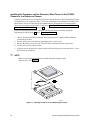
system is placed into a halt state. This feature makes is difficult to break the password by the “trial
and error” method. When entering a password, the backspace key is accepted as a character of the
password. Pressing the backspace key to replace a mistyped character will result in a wrong
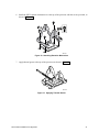
password.
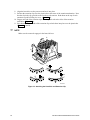
If the user or administrator password is lost or forgotten, the password clear jumper can be used to
clear both passwords. See Chapter 5 under “Clearing the Passwords with the Password Clear
Jumper.”
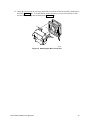
If only the administrator password is set, you:
• Must enter the administrator password to enter BIOS Setup.
• Must enter the administrator password to boot the server if Password on Boot is enabled in the
BIOS Setup.
• Must enter the administrator password to exit secure mode.
If both passwords are set, you:
• May enter the user password to enter BIOS Setup. However, you will not be able to change
many of the options.
• Must enter the administrator password if you want to enter BIOS Setup and have access to all
of the options.
• May enter either password to boot the server if Password on Boot is enabled in the BIOS Setup.
• May enter either password to exit secure mode.
Setting Passwords
Each password can be independently set or cleared in the BIOS setup utility or in the System Setup
Utility. The passwords can be up to seven characters long and can contain only alphanumeric
characters (a-z, 0-9). Numbers from the NumLock pad are recognized as different characters than
the numbers in the top row of a standard PS/2 keyboard. The passwords are not case-sensitive.
When set, a password can be cleared by changing it to a null string.
Description
27
Intrusion Switch Monitoring
To help prevent unauthorized entry or use of the server, the Intel Server Management software
monitors the chassis intrusion switch if one is installed in the chassis. Opening an access cover will
transmit an alarm signal to the server board, where BMC firmware and server management
software process the signal. The system can be configured through ISM to respond to an intrusion
a number of ways, including powering down or locking the keyboard.
Floppy Write Protection
When selected in Setup, the option for floppy write protection prevents writes to the floppy disk
while the system is in secure mode. Floppy write protection is in effect only while the system is in
secure mode. When not in secure mode, write protection is disabled and the floppy diskette drive
operates normally.
Fixed Disk Boot Sector Write Protect
The fixed disk write-protect switch is set to “Write Protect” to prevent writes to the fixed IDE disk
boot sector. This feature works only with IDE drives and only the boot sector is write protected.
Power Switch Mask
The power switch mask enables and disables the power button feature. If it set to masked, the
system power cannot be turned off with the power button after booting the operating system.
Termination is also disabled. Termination is a feature that terminates system power when the
power switch is held down for more than four seconds.
28
Intel Server Board SE7501BR2 Product Guide
2 Server Board Installations and Upgrades
Tools and Supplies Needed
•
•
•
•
•
Phillips† (cross head) screwdriver (#1 bit and #2 bit)
Needle nosed pliers
A ruler
Pen or pencil
Antistatic wrist strap and conductive foam pad (recommended)
Before You Begin
Emissions Disclaimer
To ensure EMC compliance with your local regional rules and regulations, the final configuration
of your end system product may require additional EMC compliance testing. For more information
please contact your local Intel Representative.
See “Regulatory and Integration Information” on page 121 for product Safety and EMC regulatory
compliance information. This is an FCC Class A device. Integration of it into a Class B chassis
does not result in a Class B device.
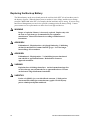
Safety Cautions
These warnings and cautions apply throughout this chapter. Only a technically qualified person
should configure the server board.
CAUTIONS
System power on/off: The power button DOES NOT turn off the system
AC power. To remove power from system, you must unplug the AC power
cord from the wall outlet. Make sure the AC power cord is unplugged before
you open the chassis, add, or remove any components.
Hazardous conditions, devices & cables: Hazardous electrical
conditions may be present on power, telephone, and communication cables.
Turn off the server and disconnect the power cord, telecommunications
systems, networks, and modems attached to the server before opening it.
Otherwise, personal injury or equipment damage can result.
Risk of burn: If the server has been running, any installed processor and
heat sink on the processor will be hot. To avoid the possibility of a burn, be
careful when removing or installing server board components that are located
near processors.
29
Electrostatic discharge (ESD) & ESD protection: ESD can damage
disk drives, boards, and other parts. We recommend that you perform all
procedures in this chapter only at an ESD workstation. If one is not
available, provide some ESD protection by wearing an antistatic wrist strap
attached to chassis groundany unpainted metal surfaceon your server
when handling parts.
ESD and handling boards: Always handle boards carefully. They can
be extremely sensitive to ESD. Hold boards only by their edges. After
removing a board from its protective wrapper or from the server, place the
board component side up on a grounded, static free surface. Use a
conductive foam pad if available but not the board wrapper. Do not slide
board over any surface.
Installing or removing jumpers: A jumper is a small plastic encased
conductor that slips over two jumper pins. Some jumpers have a small tab on
top that you can grip with your fingertips or with a pair of fine needle nosed
pliers. If your jumpers do not have such a tab, take care when using needle
nosed pliers to remove or install a jumper; grip the narrow sides of the
jumper with the pliers, never the wide sides. Gripping the wide sides can
damage the contacts inside the jumper, causing intermittent problems with
the function controlled by that jumper. Take care to grip with, but not
squeeze, the pliers or other tool you use to remove a jumper, or you may
bend or break the stake pins on the board.
Safety and Regulatory Compliance
See “Regulatory and Integration Information” on page 121 for product Safety and EMC regulatory
compliance information.
Intended uses: This product was evaluated for use in servers that will be installed in offices,
computer rooms, and similar locations. Other uses require further evaluation.
EMC testing: Before computer integration, make sure that the chassis, power supply, and other
modules have passed EMC testing using a server board with a microprocessor from the same
family (or higher) and operating at the same (or higher) speed as the microprocessor used on this
server board.
Server board diagram label provided: Place the label inside the chassis in an easy-to-see location,
preferably oriented similarly to the server board.
30
Intel Server Board SE7501BR2 Product Guide
Minimum Hardware Requirements
To avoid integration difficulties and possible board damage, your system must meet the following
minimum requirements. For a list of qualified memory and chassis components see:
http://support.intel.com/support/motherboards/server/SE7501BR2
Processor
Minimum of one Intel Xeon processor with 512K cache support. For a complete list of supported
processors, see:
http://support.intel.com/support/motherboards/server/SE7501BR2
Memory
Minimum of two 128 MB ECC, DDR266 compliant registered DIMMs on 184-pin gold DIMMs.
Power Supply
Minimum of 450 W. Your supply must provide a minimum of 1.2 A of 5 V standby current or the
board will not boot.
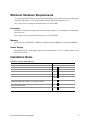
Installation Notes
Installation Process Quick Reference
Step
Remove the access cover
Where the information is located
Your chassis manual
Install the I/O shield
Page 32
Install the standoffs
Page 34
Install the rubber bumper
Page 35
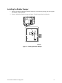
Install the server board
Page 36
Connect cables to the server board
Page 37. Refer also to your chassis
manual
Install the processor and processor wind tunnel in the Intel® Server
Chassis SC5200 base chassis or in a reference chassis
Page 40
Install the processor in the Intel® Server Chassis SC5200 with Hot
Swap Redundant Power
Page 47
Install memory
Page 52
Server Board Installation and Upgrades
31
Installation Procedures
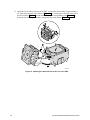
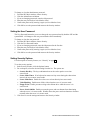
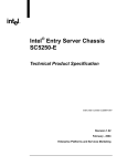
Installing the I/O Gasket and Shield
✏
NOTE
An ATX 2.03-compliant I/O shield is provided with the server board. The
shield is required by Electromagnetic Interference (EMI) regulations to
minimize EMI. If the shield does not fit the chassis, obtain a properly sized
shield from the chassis supplier.
Attaching the Gasket to the I/O Shield
1. Remove the backing strip from the gasket.
2. Press the gasket onto the inside face of the I/O shield as shown.
OM14074
Figure 3. Attaching the Gasket to the I/O Shield
32
Intel Server Board SE7501BR2 Product Guide
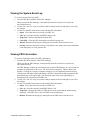
Attaching the Label to the I/O Shield
1. Remove the backing from the label included with your server board.
2. Press the label onto the outside face of the I/O shield.
US
B
1
2
3
MO
US
E
KY
BD
PA
RA
LL
EL
Outside face
of I/O shield
10/1NET
00
MB
OM14360
Figure 4. Attaching the Label to the I/O Shield
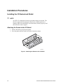
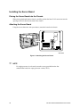
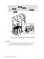
Installing the I/O Shield
The shield fits the rectangular opening in the back of a chassis. The shield has cutouts that match
the I/O ports on the server board. Install the shield from inside the chassis before installing the
server board.
1. Position one edge so that the dotted groove is outside the chassis wall, and the lip of the shield
rests on the inner chassis wall.
2. Hold the shield in place, and push it into the opening until it is seated. Make sure the I/O shield
snaps into place all the way around.
Insert top edge
as shown.
Shield installs
from inside
of chassis.
Chassis back
Chassis back
Rotate into chassis opening
until shield clicks into place.
OM14625
Figure 5. Installing the I/O Shield
Server Board Installation and Upgrades
33
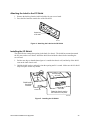
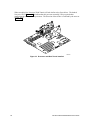
Installing Chassis Standoffs
If your chassis does not have standoffs placed as shown below, you must rearrange them so they
match the holes in the server board. Failure to properly rearrange the metal standoffs may cause the
server board to malfunction and may permanently damage it.
✏
NOTE
The Intel SC5200 chassis comes with positions 1, 4, 5, 6, 18, 20, 23, and 26
preinstalled. Install standoffs in the remaining positions (16, 19, and the
eight marked P). Install standoffs in the eight positions marked P, regardless
of whether one or two processors will be installed. Standoffs are included
with your chassis. Your chassis may be different from the illustration.
1
4
P
P
P
P
P
P
P
P
18
5
6
16 19
20
23
26
OM14626
Figure 6. Configuring Chassis Standoffs
34
Intel Server Board SE7501BR2 Product Guide
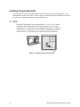
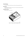
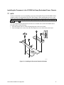
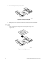
Installing the Rubber Bumper
1. Measure and mark the bumper placement location in your chassis by placing your ruler against
the standoffs as shown below.
2. Remove the backing from the bumper and press it firmly into position in the chassis.
1
4
6
7
8
20
P
P
P
P
P
P
P
7 P
0
18
19
23
26
3"
(7.6 cm)
OM14835
Figure 7. Installing the Rubber Bumper
Server Board Installation and Upgrades
35
Installing the Server Board
Placing the Server Board into the Chassis
When placing the board into the chassis, carefully position the board’s I/O connectors into the
openings in the I/O shield on the back of the chassis.
Attaching the Server Board
Using the screws that came with your chassis, mount the board to the chassis.
1
2
OM14836
Figure 8. Attaching the Server Board
✏
NOTE
If a single processor is to be used, insert the screws provided into the four
standoffs that border the empty processor socket (CPU2).
36
Intel Server Board SE7501BR2 Product Guide
Making Connections to the Server Board
4
A
B
C
4
D
K
E
J
A
T
A
1
0
0
I
F
H
G
OM14422
A. Auxiliary Power
B. Main Power
C. CPU1 Fan
D. CPU2 Fan
E. Processor Power
F. System Fans 6, 5, 4, 3 (reading
from top to bottom)
G.
H.
I.
J.
K.
Front Panel
Chassis Intrusion
ATA 100 IDE
Floppy Disk Drive Connector
System Fans 1, 2 (reading
from top to bottom)
Figure 9. Making Connections to the Server Board
Server Board Installation and Upgrades
37
Cable Routing
To ensure proper airflow within the chassis, follow the cable routing guidelines below.
SCSI Cables
SCSI cables that connect to devices in the lower device bays should be routed around the fan
housing and ducts as shown below.
Floppy Drive Cable
Route the floppy drive cable as shown.
Route cables here
OM14641
Figure 10. Routing the SCSI and Floppy Drive Cable
38
Intel Server Board SE7501BR2 Product Guide
Installing or Replacing Processor(s)
✏
NOTES
Use the instructions provided below to install or replace a processor.
Processor installation instructions provided with the boxed processor may be
different; the instructions in this document take precedence. If a single
processor is to be used, it must be installed in the processor socket labeled
CPU1. This socket is located closest to the corner of the server board.
When installing a second processor, verify that the processors are identical
and of the same voltage and speed. Do not mix processors of different types
or frequencies.
CAUTIONS
Processor must be appropriate: You may damage the server board if
you install a processor that is inappropriate for your server. Make sure your
server can handle a newer, faster processor (thermal and power
considerations). For exact information about processor interchangeability,
contact your customer service representative or visit the Intel Customer
Support website:
http://support.intel.com/support/motherboards/server/SE7501BR2
ESD and handling processors: Reduce the risk of electrostatic
discharge (ESD) damage to the processor by doing the following: (1) Touch
the metal chassis before touching the processor or server board. Keep part of
your body in contact with the metal chassis to dissipate the static charge
while handling the processor. (2) Avoid moving around unnecessarily.
If you are adding a second processor to your system, you must verify that the
second processor is identical to the first processor, same voltage and speed.
Using non-identical processors could cause system failure.
Server Board Installation and Upgrades
39
Installing the Processor and the Processor Wind Tunnel in the SC5200
Chassis or in a Reference Chassis
Use these instructions if you are installing a processor and the Processor Wind Tunnel (PWT) in the
SC5200 chassis or in a reference chassis. If you are installing the Server Board SE7501BR2 in the
Intel® Server Chassis SC5200 Hot Swap Redundant Power, disregard this section and instead
follow the instructions provided in the section titled, “Installing the Processor in the SC5200 Hot
Swap Redundant Power Chassis” on page 47.
If you are replacing a processor for which the PWT has already been installed, follow the
instructions provided on page 51 titled, “Replacing a Processor.”
1. Observe the safety and ESD precautions at the beginning of this chapter and the additional
precautions given here.
2. Remove power from your system by unplugging the AC power cord.
3. Remove the chassis cover (see your system or chassis documentation for instructions).
4. Lift the socket lever for the processor.
5. Align the pins of the processor with the socket, and insert the processor into the socket. Lower
the socket lever completely.
✏
NOTE
Make sure the alignment triangle mark and the alignment triangle cutout
align correctly. See Figure 11.
A
B
OM15042
Figure 11. Opening Socket Lever and Attaching Processor
40
Intel Server Board SE7501BR2 Product Guide
6. Install the PWT retention mechanism over the top of the processor with the screws provided, as
shown in Figure 12.
OM15037
Figure 12. Attaching Retention Mechanism
7. Apply thermal grease to the top of the processor as shown in Figure 13.
OM15040
Figure 13. Applying Thermal Grease
Server Board Installation and Upgrades
41
8. Align the heat sink over the processor and set it into place.
9. Position the retention clips over the plastic tabs at the center of the retention mechanism. Note
that the slot in the clip provides room for side-to-side motion. Push down on the top of each
retention clip while sliding it to over. (Figure 14, 1).
10. Engage each end of the retention clips over the plastic tabs at the sides of the retention
mechanism (Figure 14, 2).
11. Press downward on the ends of the retention clips to lock them into place over the plastic tabs
(Figure 14, 3 and 4).
✏
NOTE
Make sure the center tab engages in the heat sink base.
A
C
B
C
E
1
3
2
4
D
OM15039A
Figure 14. Attaching the Heat Sink and Retention Clip
42
Intel Server Board SE7501BR2 Product Guide
12. Attach the fan between the two large plastic tabs at each side of the fan assembly component of
the PWT (Figure 15, B). To ensure that the airflow direction is correct, insert the fan so that
the label shows through the assembled unit (Figure 15, A).
B
A
B
C
OM15041
Figure 15. Attaching the Wind Tunnel Fan
Server Board Installation and Upgrades
43
13. Attach the fan assembly to the top of the PWT. Position the fan assembly at approximately a
45o angle and engage the clip as shown in Figure 16, 1. Gently squeeze the tabs at the side of
the fan assembly (Figure 16, 2) and insert them into the corresponding slots (Figure 16, 3).
Rotate the fan assembly downward to engage the clips at the bottom (Figure 16, 4).
2
2
1
3
4
OM15044
Figure 16. Attaching the Heat Sink Fan to the Top of the PWT
44
Intel Server Board SE7501BR2 Product Guide
14. Attach the fan assembly to the retention mechanism. Pull the tabs at the sides of the retention
mechanism apart slightly. See Figure 17, 1. Lower the fan assembly into the retention
mechanism. The tabs on the fan assembly (Figure 17, 3) will fit into the slots of the retention
mechanism (Figure 17, 1). Pull out on the tabs located at the bottom of the fan assembly to
snap them into place on the OUTSIDE of the retention mechanism (Figure 17, 2).
15. Attach CPU Fan 1 cable to the server board at location J7F21 and/or attach CPU Fan 2 cable at
location J5F1. (Figure 17, 4.)
3a
2a
1
1
4
3b
2b
OM15045
Figure 17. Attaching the Top Assembly to the Retention Mechanism
✏
NOTE
System airflow should be from front to back. Make sure the PWT is aligned
so the fan is toward the front of the chassis and the airflow is toward the I/O
shield. If two processors are installed, the fans should be side by side.
Server Board Installation and Upgrades
45
When assembled, the Processor Wind Tunnel will look similar to the figure below. The dashed
lines over CPU2 (Figure 18, B) indicate that this processor assembly is only required when
configuring the server with two processors. The direction of the airflow is indicated by the arrow at
(Figure 18, C).
A
B
C
OM15038
Figure 18. Processor and Wind Tunnel Installed
46
Intel Server Board SE7501BR2 Product Guide
Installing the Processor in the SC5200 Hot Swap Redundant Power Chassis
✏
NOTE
Use these instructions if you are installing a processor in the Intel® Chassis SC5200 HSRP. When
using this chassis, do not install the Processor Wind Tunnel. When installing the processor in any
chassis other than the HSRP, disregard this section and follow the instructions in the section titled
“Installing the Processor and the Processor Wind Tunnel in the SC5200 Chassis or in a Reference
Chassis” on page 40.
Two sets of RM (Retention Mechanism) brackets are included with each SC5200 HSRP chassis.
For each bracket, do the following:
1. Place the bracket (letter A in the following diagram) on the server board.
2. Insert and tighten two screws (letter B in the diagram) to secure the bracket to the board.
B
A
OM14144
Figure 19. Installing the Processor Retention Brackets
Server Board Installation and Upgrades
47
3. Raise the locking bar on the processor socket.
OM14132
Figure 20. Raising the Locking Bar
4. Aligning the pins of the processor with the socket, insert the processor into the socket.
✏
NOTE
Make sure the alignment triangle mark and the alignment triangle cutout
align correctly.
OM14133
Figure 21. Installing Processors
48
Intel Server Board SE7501BR2 Product Guide
5. Lower the locking bar completely.
OM14135
Figure 22. Lower Locking Bar
6. Apply thermal grease to the top of the processor as shown.
OM14366
Figure 23. Applying Thermal Grease
Server Board Installation and Upgrades
49
7. Position the heat sink above the processor
8. Aligning the raised metal surfaces, place the heat sink on top of the processor.
OM14134
Figure 24. Installing the Heat Sink
50
Intel Server Board SE7501BR2 Product Guide
9. Place the heat sink clip (1) so the tab on the clip engages the slot on the heat sink (A).
10. Press one end of the clip down (2).
11. Press the other end of the clip down (3).
2
1
A
3
OM14140
Figure 25. Installing the Heat Sink Clip
Replacing a Processor
1. Observe the safety and ESD precautions at the beginning of this chapter and the additional
cautions given here.
2. Unplug the processor fan cable from the server board.
3. For a chassis in which a PWT assembly is used, detach the fan assembly from the PWT
retention mechanism by unlatching the clips at the bottom of the fan assembly and then lifting
up on the fan assembly.
4. Remove the metal retention clips from the bottom of the retention mechanism. Unhook each
side of each clip and disengage the center latch.
5. Remove the heat sink by slightly spreading the sides of the retention mechanism and lifting
straight up on the heat sink.
6. Raise the socket lever on the processor socket.
7. Remove the processor from the socket.
8. Align the pins of the replacement processor with the socket, and insert the processor into the
socket. Lower the socket lever completely.
✏
NOTE
Make sure the alignment triangle mark and the alignment triangle cutout
align correctly.
Server Board Installation and Upgrades
51
9. Re-insert the heat sink over the top of the processor.
10. Install new retention clips. Use the retention clips that shipped with the new processor or use a
new set. Retention clips may differ from one processor to processor and should not be reused.
See Figure 14.
✏
NOTE
When the SC5200 Hot Swap Redundant Chassis is used, disregard steps 11 and 12.
11. For chassis that require the PWT assembly, reattach the fan assembly to the retention
mechanism. Pull the tabs at the sides of the retention mechanism apart slightly.
See Figure 17, 1. Lower the fan assembly into the retention mechanism. The tabs on the fan
assembly (Figure 17, 3) will fit into the slots of the retention mechanism (Figure 17, 1). Pull
out on the tabs located at the bottom of the fan assembly to snap them into place on the
retention mechanism.
12. For chassis that require the PWT assembly, reattach the CPU fan.
Installing Memory
The server board supports only DDR266 compliant DIMMs. The minimum supported memory
configuration is 256 MB, using two 128 MB DIMMs. The maximum configurable memory size is
8 GB using four 2 GB DIMMs.
DIMMs must be installed in pairs and must be populated per bank starting with DIMM 1A and 1B
(contiguous sockets). Although the SE7501BR2 server board architecture allows the user to mix
various sizes of DIMMs between banks, DIMMs must be identical within the banks. For a list of
tested memory, see:
http://support.intel.com/support/motherboards/server/SE7501BR2
DIMM 1A
DIMM 1B
DIMM 2A
DIMM 2B
OM14665
Figure 26. Installing Memory
52
Intel Server Board SE7501BR2 Product Guide
Finishing Up
WARNING
An electrical shock hazard exists if the chassis cover is not replaced
before connecting the chassis to the main power.
1.
2.
3.
4.
Install the chassis cover according to the instructions for your chassis.
See your chassis documentation to complete rack or pedestal installation.
Connect the keyboard, mouse and monitor cables to the back panel.
Connect the power cable to the back panel and to an AC outlet.
A
C
E
D
B
G
F
I
H
OM14669
Figure 27. Making Back Panel Connections
Server Board Installation and Upgrades
53
Replacing the Back up Battery
The lithium battery on the server board powers the real time clock (RTC) for at least three years in
the absence of power. When the battery starts to weaken, it loses voltage, and the server settings
stored in CMOS RAM in the RTC (for example, the date and time) may be wrong. If you are using
Intel Server Management you can set it to provide a warning prior to the battery failing. Contact
your customer service representative or dealer for a list of approved devices.
WARNING
Danger of explosion if battery is incorrectly replaced. Replace only with
the same or equivalent type recommended by the equipment
manufacturer. Discard used batteries according to manufacturer’s
instructions.
ADVARSEL!
Lithiumbatteri - Eksplosionsfare ved fejlagtig håndtering. Udskiftning
må kun ske med batteri af samme fabrikat og type. Levér det brugte
batteri tilbage til leverandøren.
ADVARSEL
Lithiumbatteri - Eksplosjonsfare. Ved utskifting benyttes kun batteri
som anbefalt av apparatfabrikanten. Brukt batteri returneres
apparatleverandøren.
VARNING
Explosionsfara vid felaktigt batteribyte. Använd samma batterityp eller
en ekvivalent typ som rekommenderas av apparattillverkaren. Kassera
använt batteri enligt fabrikantens instruktion.
VAROITUS
Paristo voi räjähtää, jos se on virheellisesti asennettu. Vaihda paristo
ainoastaan laitevalmistajan suosittelemaan tyyppiin. Hävitä käytetty
paristo valmistajan ohjeiden mukaisesti.
54
Intel Server Board SE7501BR2 Product Guide
1. Observe the safety and ESD precautions at the beginning of this chapter.
2. Open the chassis.
3. Insert the tip of a small flat bladed screwdriver, or equivalent, under the tab in the plastic
retainer. Gently push down on the screwdriver to lift the battery.
4. Remove the battery from its socket.
OM14666
Figure 28. Replacing the Backup Battery
5. Dispose of the battery according to local ordinance.
6. Remove the new lithium battery from its package, and, being careful to observe the correct
polarity, insert it in the battery socket.
7. Close the chassis.
8. Run Setup to restore the configuration settings to the RTC.
Server Board Installation and Upgrades
55
56
Intel Server Board SE7501BR2 Product Guide
3 POST and the BIOS Setup Utility
This chapter describes the Power-On Self-Test (POST) and the BIOS Setup utility.
Power-On Self-Test (POST)
Each time you turn on the system, the BIOS begins executing the Power-On Self-Test (POST),
which is stored in flash memory. POST discovers, configures, and tests the processors, memory,
keyboard, and most installed peripheral devices. During the memory test, POST displays the
amount of memory that it is able to access and test. The time needed to test memory depends on
the amount of memory installed.
1. Turn on your server and monitor. After a few seconds, POST begins to run and displays a
splash screen.
2. While the splash screen is displayed do one of the following:
• Press <F2> to enter the BIOS Setup
• Press <Esc> to view POST diagnostic messages and change the boot device priority for this
boot only (see “Temporarily Changing the Boot Device Priority” below).
3. If you do not press <F2> or <Esc> and do NOT have a device with an operating system loaded,
the boot process continues and the system beeps once. The following message is displayed:
Operating System not found
What appears on the screen after this depends on whether you have an operating system loaded and
if so, which one.
If the system halts before POST completes running, it emits a beep code indicating a fatal system
error that requires immediate attention. If POST can display a message on the video display screen,
it causes the speaker to beep twice as the message appears.
Write down both the screen display and the beep code you hear; this information is useful for your
service representative. For a listing of common beep codes and error messages that POST can
generate, see the “Solving Problems” chapter in this manual.
Temporarily Changing the Boot Device Priority
During POST, you can change the boot device priority for the current boot process. The changes
are not saved for the next boot process.
1. Boot the server.
2. At any time during POST, press <Esc>. When POST completes, a popup Boot menu displays.
3. Use the arrow keys to highlight the device you want the server system to boot from first. For
example, if you want the server system to boot from the CD-ROM first, you select “ATAPI
CD-ROM Drive.”
✏✏
NOTE
One of the selections on the popup Boot menu is “Enter Setup.” Selecting this
option brings you into the BIOS Setup.
4. Press <Enter> and the boot process continues.
57
BIOS Setup
You can run BIOS Setup with or without an operating system being present. BIOS Setup stores
most of the configuration values in battery-backed CMOS; the rest of the values are stored in flash
memory. The values take effect when the system is booted. POST uses these values to configure
the hardware. If the values and the actual hardware do not agree, POST generates an error
message.
Record your BIOS Setup settings. If default values ever need restoring (after a CMOS clear, for
example), you must run BIOS Setup again. Your record will make this much easier.
If BIOS Setup Is Inaccessible
If you are not able to access BIOS Setup, you might need to clear the CMOS memory. To clear
CMOS, either of two methods can be used:
• Press the reset button and hold it down for four seconds or more, and then, while holding the
reset button down, press the power button. Release both buttons at the same time
OR
• Move the Clear CMOS jumper found on the configuration jumper block on the baseboard.
Starting Setup
You can enter and start Setup under several conditions:
• When you turn on the server, after POST completes the memory test
• When you have moved the CMOS jumper on the server board to the “Clear CMOS” position
(enabled). For instructions on moving the jumper, see Chapter 5, under the heading “Clearing
CMOS with the CMOS Jumper”
In these two conditions, after rebooting, you will see this prompt:
Press <F2> to enter SETUP
•
In a third condition, when CMOS/NVRAM has been corrupted, you will see other messages
but not the <F2> prompt:
Warning:
Warning:
CMOS checksum invalid
CMOS time and date not set
In this condition, the BIOS will load default values for CMOS and attempt to boot.
58
Intel Server Board SE7501BR2 Product Guide
Setup Menus
Each Setup menu page contains a number of features. Except those used for information purposes,
each feature is associated with a value field that contains user-selectable parameters. Parameters
may be changed depending upon the security option chosen. If a value is not changeable due to
insufficient security privileges (or other reasons), the feature’s value field becomes inaccessible.
The bottom portion of the Setup screen provides a list of commands that are used for navigating the
Setup utility.
Table 6.
Press
Keyboard Commands
Description
<F1>
Help - Pressing F1 on any menu invokes the general Help window.
←→
The left and right arrow keys are used to move between the major menu pages. The keys have
no affect if a submenu or pick list is displayed.
↑
Select Item up - The up arrow is used to select the previous value in a menu item’s option list, or
a value field pick list. Pressing the Enter key activates the selected item.
↓
Select Item down - The down arrow is used to select the next value in a menu item’s option list,
or a value field pick list. Pressing the Enter key activates the selected item.
F5/-
Change Value - The minus key or the F5 function key is used to change the value of the current
item to the previous value. This key scrolls through the values in the associated pick list without
displaying the full list.
F6/+
Change Value - The plus key or the F6 function key is used to change the value of the current
menu item to the next value. This key scrolls through the values in the associated pick list
without displaying the full list. On 106-key Japanese keyboards, the plus key has a different
scan code than the plus key on the other keyboard, but it has the same effect.
<Enter>
Execute Command - The Enter key is used to activate submenus when the selected feature is a
submenu, or to display a pick list if a selected feature has a value field, or to select a sub-field for
multi-valued features like time and date. If a pick list is displayed, the Enter key will undo the
pick list, and allow another selection in the parent menu.
<Esc>
Exit - The ESC key provides a mechanism for backing out of any field. This key will undo the
pressing of the Enter key. When the ESC key is pressed while editing any field or selecting
features of a menu, the parent menu is re-entered. When the ESC key is pressed in any
submenu, the parent menu is re-entered. When the ESC key is pressed in any major menu, the
exit confirmation window is displayed and the user is asked whether changes can be discarded.
<F9>
Setup Defaults - Pressing F9 causes the following to appear:
Setup Confirmation
Load default configuration now?
[Yes] [No]
If “Yes” is selected and the Enter key is pressed, all Setup fields are set to their default values. If
“No” is selected and the Enter key is pressed, or if the ESC key is pressed, the user is returned
to where they were before F9 was pressed without affecting any existing field values.
<F10>
Save and Exit - Pressing F10 causes the following message to appear:
Setup Confirmation
Save Configuration changes and exit now?
[Yes] [No]
If “Yes” is selected and the Enter key is pressed, all changes are saved and Setup is exited. If
“No” is selected and the Enter key is pressed, or the ESC key is pressed, the user is returned to
where they were before F10 was pressed without affecting any existing values.
POST and the BIOS Setup Utility
59
Table 7.
On-Screen Options
When you see this:
What it means:
On screen, an option is shown but you
cannot select it or move to that field.
You cannot change or configure the option in that menu screen.
Either the option is auto-configured or auto-detected, or you must
use a different Setup screen.
Press <Enter> to display a submenu that is either a separate full
screen menu or a popup menu with one or more choices.
On screen, the phrase Press Enter
appears next to the option.
Menu Selection Bar
The Menu Selection Bar is located at the top of the screen and displays the major menu selections
available to the user.
Table 8.
Main
Menu Selection Bar
Advanced
Security
Allocates
resources for
hardware
components
Configures
advanced
features
available
through the
chipset
Server
Sets and clears Information on
passwords and Vendor,
security features Processor,
Memory,
Peripherals, and
BIOS
Boot
Exit
Selects boot
options and
power supply
controls
Saves or
discards
changes to
Setup program
options
Main Menu
You can make the following selections from the Main Menu. Use the submenus for other
selections.
Table 9.
Main Menu Selections
Feature
System Time
Choices
HH:MM:SS
System Date
Floppy A
MM/DD/YYYY
Not installed
1.44/1.25 MB, 3.5-inch
2.88 MB
Disabled
3 seconds
6 seconds
9 seconds
12 seconds
15 seconds
21 seconds
30 seconds
<Enter>
Hard Disk Pre-delay
Primary IDE Master
Description
Sets the system time (hour, minutes, seconds, on
24 hour clock).
Sets the system date (month, day, year).
Selects the diskette type.
Provides time to allow drives that spin-up slower to
become ready.
Displays the IDE device selection. Enters submenu.
continued
60
Intel Server Board SE7501BR2 Product Guide
Table 9.
Main Menu (continued)
Primary IDE Slave
Secondary IDE Master
Secondary IDE Slave
Processor Settings
Language
Table 10.
<Enter>
<Enter>
<Enter>
<Enter>
English (US)
Spanish
Italian
French
German
Displays IDE device selection. Enters submenu.
Displays IDE device selection. Enters submenu.
Displays IDE device selection. Enters submenu.
Enters submenu.
Selects the language displayed by the BIOS.
When English (US) or one of the other Latin-based
languages is selected, the full 8-bit ASCII character
will be redirected in the format selected under the
serial console redirection submenu.
Primary/Secondary, Master/Slave Submenu
Feature
Choices
Description
Type
None
Auto
Auto instructs the system to automatically detect the
drive type.
None instructs the system to ignore this drive.
LBA Mode Control
Disabled
Enabled
Disabled
2 Sectors
4 Sectors
8 Sectors
16 Sectors
This field is informational only. It is disabled if no
devices are detected.
PIO Mode
Standard
1
2
3
3 / DMA 1
4
4 / DMA 2
This field is informational only.
It displays the method of moving data to and from the
hard drive.
Ultra DMA Mode
Mode 2
Mode 4
This field is informational only.
It displays the method of moving data to and from the
hard drive.
Multi-Sector Transfer
POST and the BIOS Setup Utility
This field is informational only and can be seen only if
an IDE hard disk drive is detected.
This field specifies the number of sectors that are
transferred per block during multiple sector transfers.
61
Table 11.
Processor Settings Submenu
Feature
Choices
Description
Processor POST Speed
Information Only
Displays the measured processor speed.
Processor Retest
Enabled
Disabled
When enabled, the BIOS will clear the processor status
history and retest all processors at the next boot. This
option automatically reverts to Disabled upon booting.
Hyper-Threading Support
Enabled
Disabled
When disabled, hyper-threading is disabled.
Processor 1 CPUID
Information Only
Reports the CPU ID for processor 1.
Processor 1 L2 Cache
Size
Information Only
Reports the L2 cache size for processor 1.
Processor 2 CPUID
Information Only
Reports the CPU ID for processor 2.
Processor 2 L2 Cache
Size
Information Only
Reports the L2 cache size for processor 2.
Advanced Menu
You can make the following selections on the Advanced Menu.
Table 12.
Advanced Menu
Feature
Choices
Description
PCI Configuration
<Enter>
Enters submenu.
Peripheral Configuration
<Enter>
Enters submenu.
Memory Configuration
<Enter>
Enters submenu.
Advanced Chipset
Control
<Enter>
Enters submenu.
This option will not be available if there are no advanced
chipset settings that can be controlled by the user.
Boot-time Diag Screen
Enabled
Disabled
When enabled, the system displays the normal POST
messages. When disabled, the logo screen is displayed.
Disabling this option disables serial redirection.
This option is not displayed if the BIOS does not detect a
valid logo in the flash file.
62
Reset Configuration Data
No
Yes
Select Yes if you want to clear the server configuration data
during the next boot. The system automatically resets this
field to No during the next boot.
Numlock
On
Off
Selects the state of the Numlock key at system power-on.
Sleep Button
Enabled
Disabled
When disabled, the sleep button will be disabled.
Intel Server Board SE7501BR2 Product Guide
Table 13.
PCI Configuration Submenu
Feature
Choices
Description
USB Function
<Enter>
Enters submenu.
On-board NIC 1
(10/100 MB)
<Enter>
Enters submenu.
On-board NIC 2 (1.0 GB)
<Enter>
Enters submenu.
On-board SCSI
<Enter>
Enters submenu.
On-board Video
<Enter>
Enters submenu.
PCI Slot 1 ROM
Enabled
Disabled
Enables or disables the option ROM scan of the device in
the selected 64-bit, 100 MHz PCI-X slot.
PCI Slot 2 ROM
Enabled
Disabled
Enables or disables the option ROM scan of the device in
the selected 64-bit, 100 MHz PCI-X slot.
PCI Slot 3 ROM
Enabled
Disabled
Enables or disables the option ROM scan of the device in
the selected 64-bit, 100 MHz PCI-X slot.
PCI Slot 4 ROM
Enabled
Disabled
Enables or disables the option ROM scan of the device in
the selected 64-bit, 100 MHz PCI-X slot. This slot supports
M-ROMB.
PCI Slot 5 ROM
Enabled
Disabled
Enables or disables the option ROM scan of the device in
the selected 32-bit, 33 MHz PCI slot.
PCI Slot 6 ROM
Enabled
Disabled
Enables or disables the option ROM scan of the device in
the selected 32-bit, 33 MHz PCI slot.
Table 14.
PCI Configuration, Embedded Devices Submenu
Feature
Choices
Description
USB Function
Enabled
Disabled
When disabled, the USB controller is disabled and the
device resources are hidden from the system.
On-board NIC 1
Enabled
Disabled
When disabled, the embedded NIC 1 is disabled and the
device resources are hidden from the system.
On-board NIC 1 ROM
Enabled
Disabled
When enabled, the NIC 1 expansion ROM is initialized.
On-board NIC 2
Enabled
Disabled
When disabled, the embedded NIC 2 is disabled and the
device resources are hidden from the system.
On-board NIC 2 ROM
Enabled
Disabled
When enabled, the NIC 2 expansion ROM is initialized.
On-board SCSI
Enabled
Disabled
When disabled, the embedded SCSI device is disabled and
the device resources are hidden from the system.
On-board SCSI ROM
Enabled
Disabled
When enabled, the SCSI device expansion ROM is
initialized.
On-board Video
Enabled
Disabled
When disabled, the embedded video is disabled and the
device resources are hidden from the system.
POST and the BIOS Setup Utility
63
Table 15.
Peripheral Configuration Submenu
Feature
Choices
Description
Serial Port A Address
Disabled
3F8h
2F8h
3E8h
2E8h
Disables Serial Port A or selects the base I/O address for
the port.
Serial Port A IRQ
4
3
Selects the IRQ for Serial Port A.
Serial Port B Address
Disabled
3F8h
2F8h
3E8h
2E8h
Disables Serial Port B or selects the base I/O address for
the port.
Serial Port B IRQ
4
3
Selects the IRQ for Serial Port B.
Parallel Port Address
Disabled
378h
278h
2BCh
Disables the onboard parallel port or selects the base I/O
address for the port.
5
7
Selects the IRQ for the parallel port.
Normal
Bi-directional
EPP
ECP
Parallel Port Modes:
Parallel Port IRQ
Parallel Port Mode
NOTE: No two devices can share the same IRQ or I/O
address. Choosing Disabled makes this port unusable.
NOTE: No two devices can share the same IRQ or I/O
address. Choosing Disabled makes this port unusable.
NOTE: Two devices cannot share the same IRQ. Also,
choosing Disabled makes the parallel port unusable.
Normal – Output only. The standard printer connection.
Bi-directional – Standard bi-directional mode.
Enhanced parallel port (EPP) – Selection based on which
EPP version the printer supports. Only choose a mode that the
parallel port device (such as a printer) supports. Check the
parallel port device documentation for this information. If this
information cannot be located, use the default setting.
Extended capabilities port (ECP) – Select only if the printer
supports it. ECP uses hardware to generate handshaking
signals, similar to EPP. However, it uses DMA channels to
move data, a FIFO buffer to send and receive data, and
real-time data compression.
64
ECP Mode DMA Channel
0
1
2
3
Selects the DMA channel for ECP mode.
Diskette Controller
Enabled
Disabled
Enables or disables the diskette controller in the Super I/O.
Legacy USB Support
Disabled
Keyboard only
Auto
Keyboard and
Mouse
If disabled, legacy USB support is turned off at the end of
BIOS POST.
Front Panel USB
Enabled
Disabled
If disabled, the front panel USB ports are inactive.
Intel Server Board SE7501BR2 Product Guide
Table 16.
Memory Configuration Submenu
Choices or
Display Only
Feature
Description
Extended Memory
Test
1 MB
1 KB
Every Location
Disabled
Selects the size of step to use during the extended RAM tests.
When disabled is selected, extended memory tests are not run.
The Every Location selection will increase the boot time.
Memory Bank #1
(DIMM 1A, 1B)
Installed
Not Installed
Disabled
Displays the current status of Memory Bank 1. Disabled indicates
that a DIMM in the bank has failed and the entire bank has been
disabled.
Memory Bank #2
(DIMM 2A, 2B)
Installed
Not Installed
Disabled
Displays the current status of Memory Bank 2. Disabled indicates
that a DIMM in the bank has failed and the entire bank has been
disabled.
Enabled
Disabled
When enabled is selected, the BIOS retests all memory on the
next boot. This option automatically reverts to disabled upon
booting.
Memory Retest
Table 17.
Advanced Chipset Control Submenu
Feature
Choices or
Display Only
Description
Wake On Ring
Enabled
Disabled
Controls legacy wake-up source
Wake On LAN
Enabled
Disabled
Controls legacy wake-up source
Wake On PME
Enabled
Disabled
Controls legacy wake-up source
Wake On RTC Alarm
Enabled
Disabled
Controls legacy wake-up source
POST and the BIOS Setup Utility
65
Security Menu
You can make the following selections from the Security Menu. Enabling the Administrator
Password field requires a password for entering Setup. Passwords are not case-sensitive.
Table 18.
Security Menu
Feature
Choices
Description
User Password is
Not Installed
Installed
Information only; once the password is set, it can be disabled by
selecting the Set Administrative Password and then setting the
password to a null string, or by using the clear password jumper on
the board.
NOTE: The clear password jumper clears both the Administrator
and User passwords.
Administrator
Password is
Not Installed
Installed
Information only; once the password is set, it can be disabled by
selecting the Set Administrative Password and then setting the
password to a null string, or by using the clear password jumper on
the board.
NOTE: The clear password jumper clears both the Administrator
and User passwords.
Set Administrative
Password
<Enter>
When the <Enter> key is pressed, you are prompted for a
password; press the ESC key to abort.
Once set, the password can be disabled by setting the password to
a null string, or by using the clear password jumper.
NOTE: If the clear password jumper is used, both the User and
Administrative passwords will be cleared.
Entering Setup with the Administrative Password provides full
access to all BIOS Setup utility menus.
Set User Password
<Enter>
When the <Enter> key is pressed, you are prompted for a
password; press the ESC key to abort.
Once set, the password can be disabled by setting the password to
a null string, or by using the clear password jumper.
NOTE: If the clear password jumper is used, both the User and
Administrative passwords will be cleared.
Password on Boot
Enabled
Disabled
Requires password entry before boot. System will remain in secure
mode until password is entered. This option is only available if a
User Password is configured.
Fixed Disk Boot
Sector
None
Write Protect
When Write Protect is enabled, the boot sector of the hard drive is
protected. This prevents viruses from corrupting the drive.
continued
66
Intel Server Board SE7501BR2 Product Guide
Table 18.
Security Menu (continued)
Feature
Choices
Description
Secure Mode Timer
1 minute
2 minutes
5 minutes
10 minutes
20 minutes
60 minutes
120 minutes
This option sets the number of minutes of PS/2 keyboard or mouse
inactivity that are allowed before Secure Mode is activated. This
option is only available if a User Password is configured.
Secure Mode Hot
Key (Ctrl-Alt-)
[L]
[Z]
Select the key combination (Ctrl-Alt-L or Ctrl-Alt-Z) to instantly put
the system into Secure Mode instead of waiting for the Secure
Mode Timer to time-out.
This option is only available if a User Password is configured.
Secure Mode Boot
Enabled
Disabled
When this option is enabled, the system will always boot directly
into Secure Mode and the user must enter a password to unlock the
system. This option is only available if a User Password is
configured.
Video Blanking
Enabled
Disabled
When enabled, the video is blank when the system is in Secure
Mode. A password is required to take the system out of Secure
Mode and restore the video. This option is only available if a User
Password is configured.
Power Switch
Inhibit
Enabled
Disabled
This option disables the power button on the front panel. When
enabled, pressing the power button has no effect.
NMI Control
Enabled
Disabled
This option enables or disables NMI control through the Baseboard
Management Controller. The NMI button is located on the front
panel.
Server Menu
You can make the following selections from the Server Menu.
Table 19.
Server Menu
Boot Priority
Device
Description
System Management
<Enter>
Enters submenu.
Console Redirection
<Enter>
Enters submenu.
Event Log Configuration
<Enter>
Enters submenu.
Fault Resilient Booting
<Enter>
Enters submenu.
Assert NMI on PERR
Enabled
Disabled
When enabled, PCI bus parity errors (PERR) cause a
system NMI.
Assert NMI on SERR
Enabled
Disabled
When enabled, PCI bus system errors (SERR) cause a
system NMI.
FRB-2 Policy
Disable BSP
Do Not Disable BSP
Retry 3 Times
Disable FRB2 Timer
This option determines when the Boot Strap Processor
should be disabled if an FRB-2 error occurs.
continued
POST and the BIOS Setup Utility
67
Table 19.
Server Menu (continued)
POST Error Pause
Enabled
Disabled
When enabled, the system will wait for user intervention if
a critical POST error is encountered.
When disabled, the system will boot without user
intervention when possible.
Boot Monitoring
Boot Monitoring Policy
PXE OS Boot Timeout
Table 20.
Disabled
5 Minutes
10 Minutes
15 Minutes
20 Minutes
25 Minutes
30 Minutes
35 Minutes
40 Minutes
45 Minutes
50 Minutes
55 Minutes
60 Minutes
This option sets the amount of time that the OS Watchdog
Timer is programmed to. When disabled, the OS
Watchdog Timer is not used.
Retry 3 Times
Retry Service Boot
Always Reset
This option configures the system response to the
expiration of the Watchdog Timer.
Disable
5 minutes
10 minutes
15 minutes
20 minutes
Controls the amount of time allowed to load the operating
system from a device that is compliant with the PXE
specification.
This option is not available if either the Hard Disk OS Boot
Timeout option or the PXE OS Boot Timeout option on the
Fault Resilient Booting Menu is not set to Disabled.
This option is not available if either the Hard Disk OS Boot
Timeout option or the PXE OS Boot Timeout option on the
Fault Resilient Booting Menu is not set to Disabled.
System Management Submenu
Boot Priority
Device
Description
Board Part Number
N/A
Information only
Board Serial Number
N/A
Information only
System Part Number
N/A
Information only
System Serial Number
N/A
Information only
Chassis Part Number
N/A
Information only
Chassis Serial Number
N/A
Information only
BIOS Revision
N/A
Information only displaying the revision of the BIOS installed
BMC Device ID
N/A
Information only
BMC Firmware Revision
N/A
Information only
continued
68
Intel Server Board SE7501BR2 Product Guide
Table 20.
System Management Submenu (continued)
Boot Priority
Device
Description
BMC Device Revision
N/A
Information only
PIA Revision
N/A
Information only
SDR Revision
N/A
Information only
Primary HSBP Revision
N/A
Information only, displaying the revision of the Hot-swap
backplane. This information is not available if the HSBP is not
detected.
Secondary HSBP
Revision
N/A
Information only, displaying the revision of the Hot-swap
backplane. This information is not available if the HSBP is not
detected.
Table 21.
Console Redirection Submenu
Feature
BIOS Redirection
Port
Choices
Serial Port A
Serial Port B
Disabled
Description
When a serial port is selected, BIOS Console Redirection is
enabled and uses the I/O port specified. Enabling this option
disables Quiet Boot.
ACPI Redirection
Port
Serial Port A
Serial Port B
Disabled
This option enables ACPI OS Headless Console Redirection.
Baud Rate
9600
19.2k
38.4k
57.6K
115.2k
This specifies the baud rate to be used when console
redirection is enabled. When the Emergency Management Port
shares the COM port for console redirection, the baud rate must
be set to 19.2k to match the baud rate for the Emergency
Management Port baud rate, unless the auto-baud feature is
used.
Flow Control
None,
CTS/RTS
XON/XOFF
CTS/RTS +CD
None disallows flow control.
CTS/RTS is hardware-based flow control.
XON/XOFF is software-based flow control.
CTS/RTS +CD is hardware-based with carrier detection flow
control.
When the Emergency Management Port shares the COM port
for console redirection, the flow control must be set to CTS/RTS
or to CTS/RTS +CD, depending on whether a modem is used.
Terminal Type
PC-ANSI
VT100+
VT-UTF8
POST and the BIOS Setup Utility
This option selects the character set to send through the serial
port when console redirection is enabled. VT-UTF8 uses
Unicode characters. VT100+ works only with English.
PC-ANSI is the standard PC-type terminal.
69
Table 22.
Event Log Configuration Submenu
Feature
Clear All Event Logs
Choices
Yes
No
Description
When Yes is selected, the BIOS will clear the System Event
Log at the next boot.
Event Logging
Enabled
Disabled
When enabled, system events are stored in the System
Event Log.
Critical Event
Logging
Enabled
Disabled
When enabled, critical events, such as PERR, SERR, ECC
memory errors, and NMI are stored in the System Event Log.
Table 23.
Fault Resilient Booting Submenu
Boot Priority
Device
Description
Late POST Timer
5 minutes
10 minutes
15 minutes
20 minutes
Disabled
This option controls the time allowed for add-in card option
ROM initialization. The system reboots if the timer runs down to
zero.
Fault Resilient Booting
Stay On
Reset
Power Off
This option controls the policy on FRB timeouts. If stay on is
selected, the server remains powered on if the FRB timer runs
down to zero. If reset is selected, the server reboots. If power
off is selected, the server is powered down.
Hard Disk OS Boot
Timeout
5 minutes
10 minutes
15 minutes
20 minutes
Disabled
This option controls the amount of time the system is allowed to
boot an operating system from a hard disk drive.
5 minutes
10 minutes
15 minutes
20 minutes
Disabled
This option controls the amount of time permitted to load the
operating system from a device that is compliant with the PXE
specification.
PXE OS Boot Timeout
70
This option is not available if the Boot Monitoring option on the
Server Menu is not set to Disabled.
This option is not available if the Boot Monitoring option on the
Server Menu is not set to Disabled.
Intel Server Board SE7501BR2 Product Guide
Boot Menu
You can make the following selections from the Boot Menu.
Table 24.
Boot Menu
Boot Priority
Device
Description
Boot Device Priority
<Enter>
Enters submenu
Hard Disk Drives
<Enter>
Enters submenu
Removable Devices
<Enter>
Enters submenu
ATAPI CD-ROM Drives
<Enter>
Enters submenu
Table 25.
Boot Device Priority Submenu
Boot Priority
Device
Description
1
Removable
Devices
The server attempts to boot from the diskette drive or remove
able device such as the LS-120.
2
Hard Drive
The server attempts to boot from a hard drive device.
3
ATAPI
CD-ROM
Drive
The server attempts to boot from an ATAPI CD-ROM drive
containing bootable media.
4
Any SCSI
CD-ROM
Drive
The server attempts to boot from a SCSI CD-ROM drive
containing bootable media. This option is available only if a
bootable CD-ROM is present. The device needs to be
controlled by a BIOS Boot Specification-compliant SCSI
option ROM.
5
PXE UNDI
The system attempts to boot from the network. This entry will
appear if there is a network device in the system that is
controlled by a PXE-compliant option ROM.
Table 26.
Hard Drive Selection Submenu
Feature
Choices
Description
Device list:
Plus (+) key
Minus (-) key
Select the boot drive with the up and down arrows to highlight
the device.
Drive #1 (or the drive
string)
Use the plus (+) key to move the selected device up in the list.
Other bootable cards
Use the minus (-) key to move the device down in the list.
Each drive with a PnP
header
“Other bootable cards” indicates boot devices that are not
reported to the system BIOS through the BIOS boot
specification mechanism. These devices may or may not be
bootable.
POST and the BIOS Setup Utility
71
Table 27.
Removable Devices Submenu
Feature
Choices
Description
Device list:
Plus (+) key
Minus (-) key
Use the plus (+) key to move the selected device up in the list.
Bootable, removable
devices
Use the minus (-) key to move the device down in the list.
Table 28.
ATAPI CD-ROM Devices Submenu
Feature
Choices
Description
Device list:
Plus (+) key
Minus (-) key
Use the plus (+) key to move the selected device up in the list.
ATAPI CD-ROM drives
Use the minus (-) key to move the device down in the list.
Exit Menu
You can make the following selections on the Exit Menu. Select an option using the up or down
arrow keys, then press <Enter> to execute the option. Pressing <Esc> does not exit this menu. You
must select one of the items from the menu or from the menu bar to exit.
Table 29.
72
Exit Menu
Choices
Description
Exit Saving Changes
Exit after writing all modified Setup item values to CMOS.
Exit Discarding Changes
Exit leaving CMOS unmodified. User is prompted if any of the setup fields
were modified.
Load Setup Defaults
Load default values for all SETUP items.
Load Custom Defaults
Load values from previously saved custom defaults. This option is not
available if no custom defaults are detected.
Save Custom Defaults
Stores custom defaults in NVRAM.
Discard Changes
Read previous values from NVRAM.
Intel Server Board SE7501BR2 Product Guide
Upgrading the BIOS
The BIOS can be upgraded in-band (operating system up) or out-of-band (operating system down).
The following instructions reflect the out-of-band upgrade steps. For in-band upgrade instructions,
refer to the Intel® Server Management Installation and User’s Guide.
Preparing for the Upgrade
Before you upgrade the BIOS, prepare for the upgrade by recording the current BIOS settings and
obtain the upgrade utility.
Recording the Current BIOS Settings
1. Boot the computer and press <F2> when you see the message:
Press <F2> Key if you want to run SETUP
2. Write down the current settings in the BIOS Setup program.
✏
NOTE
Do not skip step 2 above. You will need these settings to configure your
computer at the end of the procedure.
Obtaining the Upgrade Utility
You can upgrade to a new version of the BIOS using the new BIOS files and the BIOS upgrade
utility, iFLASH.EXE. You can obtain the BIOS upgrade file and the iFLASH.EXE utility through
your computer supplier or from the Intel Customer Support website:
http://support.intel.com/support/motherboards/server/SE7501BR2
✏
NOTE
Review the instructions distributed with the upgrade utility before
performing a BIOS upgrade.
This upgrade utility allows you to upgrade the BIOS in flash memory. The following steps explain
how to upgrade the BIOS.
Creating a Bootable Diskette
1. Use a DOS system to create the diskette.
2. Insert a diskette in diskette drive A.
3. At the C:\ prompt, for an unformatted diskette, type:
format a: /s
or, for a formatted diskette, type:
sys a:
4. Press <Enter>.
POST and the BIOS Setup Utility
73
Creating the BIOS Upgrade Diskette
The BIOS upgrade file is a compressed self-extracting archive that contains the files you need to
upgrade the BIOS.
1. Insert the bootable diskette into the diskette drive.
2. Extract the contents of the BIOS.EXE file onto the bootable diskette. To do this, type:
BIOS.EXE A:
3. The BIOS upgrade image files are extracted directly into the floppy disk.
Performing the BIOS Upgrade
1. Place the bootable diskette containing the BIOS update files into the diskette drive of your
system. Boot the system with the diskette in the drive.
2. At this point you have a choice of two options. Press 1 and <Enter> to automatically update
the system BIOS. This will update the system BIOS and reset the system. Press 2 and <Enter>
to update the User Binary and reset the system.
3. Wait while the BIOS files are updated. Do not power down the system during the BIOS update
process! The system will reset automatically when the BIOS update process is completed.
Remove the diskette from the diskette drive.
4. Verify that the BIOS version displayed during POST is the new version as the system reboots.
5. Enter Setup by pressing the F2 key during boot. Once in Setup, press the F9 and <Enter> to set
the parameters back to default values.
6. Re-enter the values you wrote down at the beginning of this process. Press F10 and <Enter> to
exit BIOS Setup and Save Changes.
7. If you do not set the CMOS values back to defaults using the F9 key, the system may function
erratically.
✏
NOTE
You may encounter a CMOS Checksum error or other problem after reboot.
Try shutting down the system and booting up again. CMOS checksum errors
require that you enter Setup, check your settings, save your settings, and
exit Setup.
It is unlikely that anything will interrupt the BIOS upgrade; however, if an interruption occurs, the
BIOS could be damaged. See “Recovering the BIOS” on page 112 for instructions.
74
Intel Server Board SE7501BR2 Product Guide
Changing the BIOS Language
You can use the BIOS upgrade utility to change the language that the BIOS uses for messages and
for the Setup program. Use a bootable diskette containing the Intel flash utility and language files.
1. Boot the computer with the bootable diskette in drive A. The BIOS upgrade utility screen
appears.
2. Select Update Flash Memory From a File.
3. Select Update Language Set. Press <Enter>.
4. Select drive A and use the arrow keys to select the correct .lng file. Press <Enter>.
5. When the utility asks for confirmation that you want to flash the new language into memory,
select Continue with Programming. Press <Enter>.
6. When the utility displays the message upgrade is complete, remove the diskette. Press
<Enter>.
7. The computer will reboot and the changes will take effect.
Hot Keys
Use the numeric pad of the keyboard to enter numbers and symbols.
Table 30.
Hot Keys
To Do This:
Press These Keys
Secure your system immediately.
<Ctrl+Alt>+hot key (Set your hot key combination with
the SSU or BIOS Setup)
Enter BIOS Setup during POST.
<F2>
Abort memory test during POST.
<ESC> (Press while BIOS is updating memory size on
screen)
Display a menu for selecting the boot device.
<ESC> (Press anytime after memory check)
To remove the splash screen.
<ESC>
POST and the BIOS Setup Utility
75
4 Configuration Software and Utilities
System Software Update Sequence
When you update the system software, you should do it in the following order.
1. Update firmware (BMC & HSC)
2. Update FRU/SDR
3. Unplug system for 30 seconds
4. Update BIOS
5. Clear CMOS
Table 31.
Configuration Utilities
Utility
Description and brief procedure
Page
Server Configuration
Wizard
Use to configure the server, including creating and modifying the
service partition, setting the system date and time, load FRU and SDR
information, set server management information, create diskettes.
78
Direct Platform Control
(DPC) Console
Use to access and monitor the server remotely.
78
System Setup Utility
(SSU) and Client
System Setup Utility
(CSSU)
Use for viewing and configuring server management options, viewing
the system event log (SEL), setting boot device priority, or setting
system security options.
81
The SSU can run either from the configuration software CD or from a
set of bootable diskettes. You can create the diskettes from the CD.
The CSSU is run from the service partition via the DPC console. It
provides the same functionality as the SSU, but is used from a remote
console.
Information entered via the SSU or /CSSU overrides information
entered via BIOS Setup.
BIOS Update Utility
Use to update the BIOS or recover from a corrupted BIOS update.
86
Firmware Update Utility
Use to update BMC flash ROM or other firmware.
91
FRU/SDR Load Utility
Use to update the Field Replaceable Unit (FRU) and Sensor Data
Record (SDR) flash components.
95
NOTE: You must run the FRU/SDR Load utility whenever the BMC is
updated or if you change your processors.
77
Server Configuration Wizard
The Server Configuration Wizard (SCW) is a utility that is provided to help you configure your
server. The Server Configuration Wizard is located on the System Resource CD-ROM shipped
with the server and it runs automatically when you boot your server to this CD-ROM. The Server
Configuration Wizard includes a help system that can be accessed by clicking the Help button.
Run the Configuration to:
• Create or update a Service Partition and install service partition files, including files that are
necessary to run the System Setup Utility
• Load FRUs and SDRs
• Set the System Asset Tag
• Set Server Management settings, including an IP address, emergency management port (EMP)
settings, platform event paging (PEP) settings, and LAN/Alert settings
• Execution utility applications that can be used to manually configure the server
• Create startup or installation diskettes for hardware device drivers and server configuration
utility applications
When it is first executed, the SCW probes the server for installed devices, firmware, chassis
information, hard disks, and other relevant data. This information is used to determine the
questions the application needs to ask you to complete the configuration.
When you select the options Server Configuration Wizard > Run Wizard, you will be shown a
selection window allowing you to choose the items you want to configure. You can select one or
more options to configure at the same time. Some options have dependencies that make you select
multiple options. These are:
• If you select Configure this server for LAN Alerting, the option for Configure this server for
remote Server Management over a LAN connection will automatically be selected.
• If you select Configure this server for Serial/Modem alerting, the option for Configure this
server for remote Server Management over a Serial/Modem connection will automatically be
selected.
In addition, you can select only one of the following at a time:
• Load SDRs only onto this server
OR
• Load FRUs and SDRs onto this server
If you select multiple options, the Server Configuration Wizard will run each option to completion.
78
Intel Server Board SE7501BR2 Product Guide
To use the Server
Configuration utility to
Description of procedure
Page
Configure the server for
remote LAN
management
Enable a connection to the server from a workstation on the LAN to
allow remote management functions, such as powering the server on or
off, or running diagnostic utilities.
87
Configure for Remote
Serial / Modem
management
Enable a connection to the server from a serial or Modem connection to
allow remote management functions, such as powering the server on or
off, or running diagnostic utilities.
88
Configure for Serial /
Modem alerting
Configure the server to send a telephone page in the event that a
hardware or firmware error occurs at the server.
91
Configure for LAN
alerting
Configure the server to send a notification message to a workstation
segment of the network in the event that a hardware or firmware error
occurs at the server.
92
Run the FRU/SDR Load
Utility
Use to update the Field Replaceable Unit (FRU) and Sensor Data
Record (SDR) flash components.
95
NOTE: You must run the FRU/SDR Load utility whenever the BMC is
updated or if you change your processors.
Configure an Asset Tag
Assign an identification number or serial number to the server.
98
Create / modify the
service partition
If a service partition does not already exist, create one. If a service
partition has been created earlier, update it.
99
Create System or Utility
/ Device Diskettes
Create diskettes by operating system, utility, or device driver.
98
Save / load
configuration data
Save the configuration data to a file. Use this saved file to configure
other servers identically.
100
Direct Platform Control (DPC) Console
Direct Platform Control (DPC) Console is part of Intel Server Management. Direct Platform
Control is a server management application that supports remote system management via LAN, or
an RS-232 serial connection to the server Serial B port over a modem or a direct serial cable. The
Direct Platform Control Console provides the ability for remote management of Intel servers via
modem or LAN with a capability to run DOS-based programs.
DPC console runs on a client workstation and is independent of the server operating system. It
communicates with a server by:
• Accessing the server management capabilities of the on-board NIC
• A Windows† 2000 compatible modem
• An RS-232 connection to the server’s Serial B port
Configuration Software and Utilities
79
Even when the server is off, you can use DPC Console to verify the state of a server or diagnose a
problem with the server hardware. DPC console features allows you to:
• Establish connection to remote servers
• Server Control: power on, power off, and reset operations
• Retrieve and display entries in the System Event Log (SEL)
• Retrieve and display Sensor Data Records (SDR)
• Retrieve and display Field Replaceable Unit (FRU) information
• Retrieve and display current Remote Sensor Access (RSA) information
• Access a phonebook for remote connection management
• Remote control of the service partition
• File transfer from / to the server
DPC Console Modes of Operation
There are four DPC console modes of operation:
• EMP mode. Access the DPC console features using the DPC console window menus and/or
toolbar. Active when a connection is established through the EMP port (Serial B).
• DPC over LAN mode. Access the DPC console features using the DPC console window
menus and/or toolbar. Active when a connection is established through the LAN.
• Re-direct mode. Active when the server is running BIOS console redirection. In this mode, the
DPC console launches a separate window. The window operates as an ANSI terminal and
communicates with the server through the port. Character-based commands you type in the
DPC Console go directly to the server, and the DPC Console displays the text that you would
normally see on the server console.
To use this mode, you must configure the Console Redirection option of BIOS Setup for
Re-direct mode. Enabling Console Redirection requires that the Boot Time Diagnostics Screen
be Enabled in BIOS Setup. If the redirection window does not display information, the
Console Redirection is either incorrectly configured or disabled, the EMP is disabled in BIOS
Setup, or the server is in protected mode. For DPC to function in this mode, the server must
NOT be in graphics mode.
•
If the DPC console fails to connect in EMP within 10 seconds and the server can operate in
Re-direct mode, a prompt is displayed with the option to switch to Re-direct mode.
Service Partition mode. Entered when the server reboots from the service partition and the
DPC Console has successfully connected to the server. This mode allows running of
DOS-based programs that are stored on the service partition of the local hard drive and
transferring of files.
Running the DPC Console
For more information about setting up and running the DPC Console, see the ISM Installation
User’s Guide. This document is in the ISM\DOCS\[language] directory on the ISM CD
accompanying the SE7501BR2 server board.
80
Intel Server Board SE7501BR2 Product Guide
Using the System Setup Utility
The System Setup Utility (SSU) is located on the System Resource CD-ROM that is shipped with
the server.
Run the System Setup Utility to:
•
•
•
•
•
•
•
•
•
Set boot device priority
Set passwords and security options
View system events
View FRU information
View sensor data records
Update system firmware and BIOS
Save and restore the system configuration
Set up the server to send alerts for platform events
Set up the server for remote management
Using either the System Setup Utility or BIOS Setup, you can specify the boot device sequence and
set up system passwords and security options. Both utilities access the same stored configuration
data for these items, and the result of making a change to these settings using either utility is
identical.
The SSU consists of a collection of task-oriented modules plugged into a common framework
called the Application Framework (AF). The Application Framework provides a launching point
for individual tasks and a location for setting customization information.
Creating SSU Diskettes
You can run the SSU from the Server Configuration Utilities menu of the Server Configuration
Wizard, from a set of DOS diskettes, or from the service partition of the hard disk.
If you choose to run the SSU from a set of DOS diskettes, you must create the SSU diskettes from
the Resource CD-ROM as follows:
1. Boot the System Resource CD-ROM to the Server Configuration Wizard.
2. Choose Create Diskettes > Create Diskettes by Device/Function > System Setup Utility.
3. Follow the instructions displayed.
Alternatively, if you have a workstation with the Microsoft Windows operating system, you can
insert the CD into that system and create the diskettes on that system.
Configuration Software and Utilities
81
Running the SSU
When the SSU starts in the default local execution mode, it accepts input from the keyboard or
mouse. The SSU presents a VGA-based GUI on the primary monitor.
If you run the SSU from read-only media you cannot save user preference settings (such as screen
colors).
The SSU supports ROM-DOS version 6.22. The SSU will not operate from a “DOS box” running
under an operating system such as Windows.
Start the SSU using one of the following methods:
• From diskettes: Insert the first SSU diskette in drive A and boot the server from the diskette.
You are prompted to insert the second diskette. After loading completes the SSU starts
automatically.
• From the System Resource CD: Boot the server to the Server Configuration Wizard and start
the SSU from the Server Configuration Utilities menu.
• From the Service Partition: Boot the server to the Service Partition and execute the following
DOS commands:
C:\> cd ssu
C:\SSU> ssu.bat
The mouse driver loads if it is available; press <Enter> to continue.
When the SSU title appears on the screen, press <Enter> to continue.
Working with the SSU Interface
You can access features of the SSU interface using the mouse or keyboard:
• Mouse: Click once to choose menu items and buttons or to select items in a list, such as the
Available Tasks list. To run a list item, such as one of from the Available Tasks list, select the
item and click OK or double-click the item.
• Keyboard: Use the tab and arrow keys to highlight buttons and press the spacebar or <Enter>
to execute. You can also execute a menu or button by using the <Alt> key in combination with
the underlined letter in the name of the menu or button.
You can have more than one task open at the same time, although some tasks might require
complete control to avoid possible conflicts. The tasks achieve complete control by keeping the
task as the center of operation until you close the task window.
The SSU has a build-in help system, which you access by clicking a Help button or choosing the
Help menu.
82
Intel Server Board SE7501BR2 Product Guide
Customizing the SSU Interface
The SSU lets you customize your interface using the Preferences section of the main window. The
AF sets these preferences and saves them in the AF.INI file so that they take effect the next time
you start the SSU. There are four user customizable settings:
• Color: lets you change the default colors associated with different items on the screen using
predefined color combinations. The color changes take effect immediately.
• Mode: lets you set the desired expertise level: novice, intermediate, or expert. The expertise
level determines which tasks are visible in the Available Tasks section and which actions each
task performs. For a new mode setting to take effect, you must exit the SSU and restart it.
• Language: lets you change the text in the SSU to the appropriate language. For a new
language setting to take effect, you must exit the SSU and restart it.
• Other: lets you show or hide the status bar at the bottom of the SSU main window. The
change takes effect immediately.
✏✏
NOTE
If you run the SSU from read-only media (CD-ROM, for example), these
preferences are lost when you exit the SSU.
Exiting the SSU
Exiting the SSU closes all SSU windows.
Setting Boot Device Priority
To change the boot priority of a device:
1. From the SSU Main window, choose Boot Devices.
2. In the Multiboot Options Add-in window, select a device.
3. Click the Move Up button to move it up in the list. Click the Move Down button to move
it down.
Setting Passwords and Security Options
You can set a user password and an administrator password for the server. You must set an
administrator password before you can set a user password. On other systems, the passwords are
independent. You can set the same passwords and security options by using BIOS Setup.
Setting the Administrator Password
The Admin Password button lets you set or change the administrator password used by both the
SSU and the system BIOS. This option is not available if both an administrator and a user
password are set and you entered only the user password when you started the SSU. All changes to
the administrator password take effect immediately.
Configuration Software and Utilities
83
To change or clear the administrator password:
1. From the SSU Main window, choose Security.
2. Click the Admin Password button.
3. If you are changing passwords, enter the old password.
4. Enter the new password (or leave blank to clear).
5. Confirm the password by entering it again (or leave blank to clear).
6. Click OK to save the password and return to the Security window.
Setting the User Password
The User Password button lets you set or change the user password used by both the SSU and the
system BIOS. All changes to the user password take effect immediately.
To change or clear the user password:
1. From the SSU Main window, choose Security.
2. Click the User Password button.
3. If you are changing passwords, enter the old password in the first box.
4. Enter the new password (or leave blank to clear).
5. Confirm the password by entering it again (or leave blank to clear).
6. Click OK to save the password and return to the Security window.
Setting Security Options
For a description of security features, see “Security” on page 25.
To set the security options:
1. In the Security window, click the Options button.
2. For each option, select the desired setting from the list. The options are:
• Security Hot Key: The key combination that can be used to put the server into
secure mode.
• Secure Mode Timer: If no keyboard or mouse activity occurs during the chosen time
interval, the server enters secure mode.
• Secure Mode Boot: Enable forces the server to boot directly into secure mode.
• Video Blanking: Enable turns off the video when the server is in secure mode.
• Floppy Write: Enable prevents writing to the diskette drive while the server is in
secure mode.
• Power Switch Inhibit: Enable prevents the power and reset buttons from functioning
when the server is in secure mode. Disable allows the power and reset buttons to function
normally when the server is in secure mode.
3. Click Save to save the settings and return to the Security window.
84
Intel Server Board SE7501BR2 Product Guide
Viewing the System Event Log
To view the System Event Log (SEL):
1. From the SSU Main window, choose SEL Manager.
When you start the SEL Manager, it automatically loads the current list of events from
non-volatile memory.
2. Use the <F4> and <F5> keys to scroll the window contents to the left and right to view all of
the columns.
3. Use the File and SEL menu items to work with the SEL information:
• Open: Views data from a previously saved SEL file.
• Save As: Saves the currently loaded SEL data to a file.
• Properties: Displays information about the SEL.
• Clear SEL: Clears the SEL data from the nonvolatile storage area.
• Reload: Refreshes the display by reading the current SEL entries from the server.
• Sort By: Sorts the displayed events by event number, time stamp, sensor type and number,
event description, or event generator ID.
Viewing FRU Information
To view the Field Replaceable Unit (FRU) information:
1. From the SSU Main window, choose FRU Manager.
When you start the FRU Manager, it automatically loads the current list of events from
non-volatile memory.
The FRU Manager window has a navigation pane on the left that displays, in a tree format, the
inventory of components in the server. The tree has three categories: Chassis, Board, and
Product. Clicking on a category expands or collapses a list of components for that category.
Clicking on an individual component displays the FRU information for that component in the
presentation pane in the upper right. The description pane in the lower right displays a
description of the currently selected FRU area.
2. Use the <F4> and <F5> keys to scroll the window contents to the left and right to view all of
the columns.
3. Use the File and FRU menu items to work with the FRU information:
• Open: Views data from a previously saved FRU file.
• Save As: Saves the currently loaded FRU data to a file.
• Properties: Displays the number of FRU devices in the system and the number being
displayed. Only FRU devices with valid FRU areas are displayed.
• Reload: Refreshes the display by reading the current FRU entries from the server.
Configuration Software and Utilities
85
Viewing Sensor Data Records
To view the Sensor Data Records (SDR):
1. From the SSU Main window, choose SDR Manager.
When you start the SDR Manager, it automatically loads the SDR entries from non-volatile
memory.
The SDR Manager window has a navigation pane on the left that displays, in a tree format, the
sensor data records. The tree has categories for each type of record. Clicking on a category
expands or collapses a list of SDRs for that category. Clicking on an individual SDR displays
the information for that SDR in the presentation pane in the upper right. The description pane
in the lower right displays a description of the currently selected SDR type.
2. Use the <F4> and <F5> keys to scroll the window contents to the left and right to view all of
the columns.
3. Use the File and SDR menu items to work with the SDR information:
• Open: Views data from a previously saved SDR file.
• Save As: Saves the currently loaded SDR data to a file.
• Properties: Displays information about the SDR, including IPMI version, number of SDR
entries, time stamps for changes to the SDR information, and free space remaining.
• Reload: Refreshes the display by reading the SDR data from the server.
Updating System Firmware and BIOS
Using the SSU, you can update the BIOS, update the firmware, and verify the firmware.
Procedures for each are given below. You can also update the BIOS and firmware without using
the SSU. You can download the updates from the Intel support website:
http://support.intel.com/support/motherboards/server
Updating the BIOS
To update the BIOS:
1. Download the update from the Intel support website.
2. From the SSU Main window, choose System Update. (System Update is available only in
Expert mode.)
When you start System Update, it automatically displays the current revision information for
the system firmware and BIOS.
3. From the File menu, choose Load and choose a .uif or .bio file to use for the update.
4. Click the Update button to update the BIOS.
86
Intel Server Board SE7501BR2 Product Guide
Updating the Firmware
To update the system firmware:
1. Download the update from the Intel support website.
2. From the SSU Main window, choose System Update. (System Update is available only in
Expert mode.)
When you start System Update, it automatically displays the current revision information for
the system firmware and BIOS.
3. From the File menu, choose Load and choose a .uif or .hex file to use for the update.
4. Click the Update button to perform the update.
Verifying the Firmware
To compare the system firmware in nonvolatile memory with a firmware file:
1. Download the update from the Intel support website.
2. From the SSU Main window, choose System Update. (System Update is available only in
Expert mode.)
When you start System Update, it automatically displays the current revision information for
the system firmware and BIOS.
3. From the File menu, choose Load and choose a .hex file to use for the update.
4. Click the Verify button to compare the firmware code in nonvolatile storage with the
selected file.
Managing the Server Remotely
You can set up the server so that you can connect to it from a remote client system to perform
management tasks and so that the server can contact you if a system error occurs. You can make
the connection over a LAN or by using a modem or direct serial cable to the Emergency
Management Port (EMP). You can set up the server to notify you when various events occur.
Alerts can be delivered either as telephone pages or over the LAN.
Instructions for setting up the server for remote LAN and serial/modem access and for setting up
the server to proactively alert or page you are given below.
How to Set Up Remote LAN Access
To set up the server so you can access it from a remote workstation, you can use either the Server
Configuration Wizard or the System Setup Utility.
To use the Server Configuration Wizard to configure remote LAN access:
1. Use the Resource CD to boot the server to the Server Configuration Wizard.
2. Select Server Configuration Wizard and Continue.
3. Select Run Wizard and Continue.
4. Select the box that says “Configure this server for remote Server Management over a LAN
connection”.
5. Review the system date and time for accuracy and Continue.
Configuration Software and Utilities
87
6. In the IP Setup screen, choose either:
• DHCP: the IP address for the server is automatically assigned by the DHCP (dynamic host
control protocol) server on the network. The Host, Gateway, and Subnet Mask boxes in the
dialog are ignored.
• Static: assign the IP address for the server using the Host, Gateway, and Subnet Mask
boxes in the dialog.
7. If you chose Static IP Setup in the previous step, fill in the IP addressing boxes:
• Host IP Address: the IP address of this server.
• Gateway IP Address: the IP address of the router for this server.
• Subnet Mask: the IP address for the server’s subnet. The server uses this to decide if the
alert destination is on the same subnet.
• Backup Gateway IP Address: (optional). The IP address of the alternate router for this
server.
8. Click Continue. Click the LAN Password button (optional) to require that a password be
entered before a user can perform server management functions on this server from a
workstation on the LAN.
9. Select the LAN Access Mode to set the points at which LAN connectivity can be activated:
• Always Available: a remote system can initiate a LAN connection, regardless of the
server’s state or health
• Restricted: power control functions, such as power down, front panel NMI, and system
reset cannot be performed remotely
• Disabled: remote LAN connections cannot be initiated
10. Select the SOL Access Mode to set the user access level that is required for connecting to the
server using Serial over LAN
• Always Available: an individual can access the server through Serial over LAN if that
user knows the server User password
• Restricted: an individual can access the server through Serial over LAN if that user knows
the server Administrator password
• Disabled: Serial over LAN cannot be used.
11. Select the baud rate and then Continue.
To use the System Setup Utility to configure remote LAN access:
1. From the SSU Main window, choose Platform Event Manager (PEM).
2. In the PEM window, click Configure LAN and fill in the boxes described in the following steps
(boxes that aren’t listed here are not required for remote access).
3. To require a password for remote access, enter the password in the Enter New Password box
and in the Verify New Password box. Passwords can be from 1 to 16 characters long, using
any ASCII character in the range [32-126]. To clear the passwords, leave both boxes blank.
(You can also clear the password by choose the menu Options > Clear LAN Password.)
88
Intel Server Board SE7501BR2 Product Guide
4. From the LAN Access Mode list, select the remote access mode:
• Always Available: a remote system can initiate a LAN connection regardless of the state
or health of the server.
• Restricted: a remote system can initiate a LAN connection, but cannot perform control
operations such as power down, reset, or front panel NMI.
• Disabled: remote systems are not allowed to initiate LAN connections.
5. In the IP Setup box, choose either:
• DHCP: the IP address for the server is automatically assigned by the DHCP (dynamic host
control protocol) server on the network. The Host, Gateway, and Subnet Mask boxes in the
dialog are ignored.
• Static: assign the IP address for the server using the Host, Gateway, and Subnet Mask
boxes in the dialog.
6. If you chose Static IP Setup in the previous step, fill in the IP addressing boxes:
• Host IP Address: the IP address of this server.
• Gateway IP Address: the IP address of the router for this server.
• Subnet Mask: the IP address for the server’s subnet. The server uses this to decide if the
alert destination is on the same subnet.
7. Click Save to save the changes.
8. Click Close to return to the PEM window.
How to Set Up Remote Modem or Serial Access
To set up the server so you can access it through a modem or a serial connection, you can use either
the Server Configuration Wizard or the System Setup Utility.
To use the Server Configuration Wizard to configure remote modem or serial access:
1. Use the Resource CD to boot the server to the Server Configuration Wizard.
2. Select Server Configuration Wizard and Continue.
3. Select Run Wizard and Continue.
4. Select the box that says “Configure this server for remote Server Management over a
Serial/Modem connection”.
5. Review the system date and time for accuracy and Continue.
6. Enter the appropriate Serial / Modem parameters and Continue.
7. Click Continue. Click the Serial/Modem Password button (optional) to require that a password
be entered before a user can perform server management functions on this server from a serial
or Modem connection.
8. Select the Access Mode to set the points at which serial / Modem connectivity can be activated:
• Preboot Only: the EMP is available only when the server is powered down or is running
POST during startup. Once the operating system is loaded, a connection cannot be made.
• Always Active: the EMP is available at any time.
• Disabled: a connection cannot be made to the server using serial / Modem access.
Configuration Software and Utilities
89
9. Select the Restricted Mode to set the restrict power control operations:
• Enable: enable restrictions. A user cannot use Serial / Modem access to affect the power
state of the system, such as powering the server on or off.
• Disable: disables restrictions. A user can choose to power the server on or off through a
Serial / Modem connection.
10. Select the Connection Mode.
• Direct Connect: Use direct connect when a system is connected directly to the server
through the Serial port, without using an external modem.
• Modem Mode: use Modem Mode when the Serial port is connected to an external
modem.
11. System Phone Number: enter the telephone number that is used to connect to this server.
12. Click Continue.
To use the System Setup Utility to configure remote modem or serial access:
1. From the SSU Main window, choose Platform Event Manager (PEM).
2. In the PEM window, click Configure EMP and fill in the boxes described in the following steps
(boxes that aren’t listed here are not required for remote access).
3. To require a password for remote access, enter the password in the Enter New Password box
and in the Verify New Password box. Passwords can be from 1 to 16 characters long, using
any ASCII character in the range [32-126]. To clear the passwords, leave both boxes blank.
(You can also clear the password by choose the menu Options > Clear LAN Password.)
4. In the Modem Ring Time box, enter the number of 500ms intervals that the BMC should wait
before taking control of the serial 2 port and answering an incoming call. A value greater than
zero gives the BIOS time to answer before the BMC takes control. A value of zero causes the
BMC to answer immediately. The maximum value, 63, tells the BMC to ignore the call.
Modem Ring Time applies only to Preboot access mode and is ignored for other access modes.
5. In the System Phone Number box, enter the number for the phone line connected to the modem
on the EMP.
6. From the Access Mode list, choose the remote access mode:
• Always Active: the EMP is available at any time.
• Preboot: the EMP is available only when the server is powered down or is running POST
during startup. Once the operating system is loaded, a connection cannot be made.
• Disabled: remote systems are not allowed to initiate connections.
7. From the Restricted Mode list, choose either:
• Enabled: a remote system can initiate a connection, but cannot perform control operations
such as power down, reset, or front panel NMI.
• Disabled: the remote system has full control of the server.
8. From the Connection Mode list, choose either:
• Direct Connect: the Serial B port on the server is connected by a serial cable to the remote
system.
• Modem Connect: the Serial B port on the server is connected to a modem.
9. Click Save to save the changes.
10. Click Close to return to the PEM window.
90
Intel Server Board SE7501BR2 Product Guide
How to Set Up Paging Alerts
To set up the server so it pages you in the event of an alert, you can use either the Server
Configuration Wizard or the System Setup Utility.
To use the Server Configuration Wizard to configure the server to send alerts as telephone pages:
1. Use the Resource CD to boot the server to the Server Configuration Wizard.
2. Select Server Configuration Wizard and Continue.
3. Select Run Wizard and Continue.
4. Select the box that says “Configure this server for Serial/Modem Alerting” The box that says
“Configure this server for remote Server Management over a Serial/Modem connection” will
be automatically selected as a dependency.
5. Review the system date and time for accuracy and Continue.
6. Enter the appropriate Serial / Modem parameters and Continue.
7. Click the Serial/Modem Password button (optional) to require that a password be entered
before a user can perform server management functions on this server from a serial or Modem
connection.
8. Select the Access Mode to set the points at which serial / Modem connectivity can be activated:
• Preboot Only: a serial or Modem connection can be made when the server is powered
down or hard reset. Once the operating system is loaded, a connection cannot be made.
• Always Active: a connection to the server can be established at any time.
• Disabled: a connection cannot be made to the server using serial / Modem access.
9. Select the Restricted Mode to set the restrict power control operations:
• Enable: enable restrictions. A user cannot use Serial / Modem access to affect the power
state of the system, such as powering the server on or off.
• Disable: disables restrictions. A user can choose to power the server on or off through a
Serial / Modem connection.
10. Select the Connection Mode:
• Direct Connect: Use direct connect when a system is connected directly to the server
through the Serial port, without using an external modem.
• Modem Mode: use modem mode when the Serial port is connected to an external modem.
11. System Phone Number: enter the telphone number that is used to connect to this server.
12. Click Continue.
13. Select the Enable Serial/Modem Paging option
14. Enter the telephone number the system should send the page if an event happens.
15. Enter the paging string the server should send after a phone connection is made.
16. Enter the Blackout Period: the time in minutes that should be allowed between pages. The
valid range is [0 - 255] where 0 disables the blackout period. Setting a blackout period can
save you from being flooded with repeat pages. After you receive a PEP page, no additional
pages are sent by PEP for the duration of the blackout period.
17. Click the Alert Paging Filters button. Click the boxes enable / disable filters. Click OK when
you are done, and then click Continue.
Configuration Software and Utilities
91
To use the System Setup Utility to set up the server to send alerts as telephone pages:
1. Install an external modem on the Emergency Management Port (Serial B).
2. From the SSU Main window, choose Platform Event Manager (PEM).
3. In the PEM window, click Configure EMP.
4. In the corresponding boxes, enter the following command strings for the modem attached to the
EMP port (boxes that aren’t listed here are not required for paging alerts):
• ESC Sequence: the escape sequence. This string is sent to the modem before sending
command strings. The maximum length for the string is five characters; longer strings are
truncated.
• Hangup String: hang up or drop the connection. The EMP automatically sends an
<ENTER> character following this string. The maximum length for the string is eight
characters; longer strings are truncated.
• Modem Dial Command: the command to dial a phone number. This string is sent to the
modem before sending the paging string.
• Modem Init String: the initialization string for the modem. This string is sent every time
the EMP initializes. The maximum length for the string is determined at run-time from
firmware. You will be notified if the string is truncated. Following a save, the actual string
saved is displayed in the edit box.
5. Click Save to save the changes.
6. Click Close to return to the PEM window.
7. In the PEM window, click Configure PEP.
8. Select the Enable PEP check box.
9. In the Blackout Period box, enter the minimum time, in minutes, between successive pages.
The valid range is [0 - 255] where 0 disables the blackout period. Setting a blackout period can
save you from being flooded with repeat pages. After you receive a PEP page, no additional
pages are sent by PEP for the duration of the blackout period.
10. In the Paging String box, enter the phone number to dial for the page and the message you want
sent with the page. The maximum length for the paging string is determined at run-time from
firmware. You will be notified if the string is truncated. Following a save, the actual string
saved is displayed in the edit box.
11. From the Options menu, choose Configure Event Actions.
12. In the Platform Event Paging Actions window, move the events that you want to generate an
alert to the Enabled column and move all other events to the disabled column using the
following buttons:
• >>: Moves all events from the enabled list to the disabled list.
• >: Moves the selected event from the enabled list to the disabled list.
• <: Moves the selected event from the disabled list to enabled the list.
• <<: Moves all events from the disabled list to the enabled list.
13. Click Save to save the changes.
14. Click Close to return to the PEP Configuration window.
15. To send a test page to verify that you have correctly configured PEP, from the Options menu,
choose Send Alert.
16. Click Save to save the configuration.
17. Click Close to return to the Platform Event Manager window.
92
Intel Server Board SE7501BR2 Product Guide
How Set Up LAN Alerts
To set up the server to send alerts over the LAN you can use either the SSU or the SCW. For more
information about LAN alerts, see the documentation for Intel Server Management software.
To use the Server Configuration Wizard to configure the server to send alerts over the LAN:
1. Use the Resource CD to boot the server to the Server Configuration Wizard.
2. Select Server Configuration Wizard and Continue.
3. Select Run Wizard and Continue.
4. Select the “Configure this server for LAN Alerting” box. The box that says “Configure this
server for remote Server Management over a LAN connection” will be automatically selected
as a dependency.
5. Review the system date and time for accuracy and Continue.
6. In the IP Setup screen, choose either:
• DHCP: the IP address for the server is automatically assigned by the DHCP (dynamic host
control protocol) server on the network. The Host, Gateway, and Subnet Mask boxes in the
dialog are ignored.
• Static: assign the IP address for the server using the Host, Gateway, and Subnet Mask
boxes in the dialog.
7. If you chose Static IP Setup in the previous step, fill in the IP addressing boxes:
• Host IP Address: the IP address of this server.
• Gateway IP Address: the IP address of the router for this server.
• Subnet Mask: the IP address for the server’s subnet. The server uses this to decide if the
alert destination is on the same subnet.
• Backup Gateway IP Address: (optional). The IP address of the alternate router for this
server.
8. Click Continue. Click the LAN Password button (optional) to require that a password be
entered before a user can perform server management functions on this server from a
workstation on the LAN.
9. Select the LAN Access Mode to set the points at which LAN connectivity can be activated:
• Always Available: a remote system can initiate a LAN connection, regardless of the
server’s state or health
• Restricted: power control functions, such as power down, front panel NMI, and system
reset cannot be performed remotely
• Disabled: remote LAN connections cannot be initiated
10. Select the SOL Access Mode to set the user access level that is required for connecting to the
server using Serial over LAN
• Always Available: an individual can access the server through Serial over LAN if that
user knows the server User password
• Restricted: an individual can access the server through Serial over LAN if that user knows
the server Administrator password
• Disabled: Serial over LAN cannot be used
11. Select the baud rate and then Continue.
12. Select the Enable LAN Alerting option.
Configuration Software and Utilities
93
13.
14.
15.
16.
Enter the IP address for the system that should receive notifications if an event happens.
Enter the SNMP Community String. The default is public.
Check the box to resolve the Gateway MAC address (optional).
Click the LAN Alert Filters button. Click the boxes enable / disable filters. Click OK when
you are done, and then click Continue.
To use the System Setup Utility to configure the server to send alerts over the LAN:
1. From the SSU Main window, choose Platform Event Manager (PEM).
2. In the PEM window, click Configure LAN and fill in the boxes described in the following steps
(boxes that aren’t listed here are not required for LAN alerts).
3. Select the Enable LAN Alerts check box.
4. (Optional) In the SNMP Community String box, enter a string for the community field in the
Header section of the SNMP trap sent for an alert. The string must be from 5 to 16 characters.
The default string is public.
5. In the IP Setup box, choose either:
• DHCP: the IP address for the server is automatically assigned by the DHCP (dynamic host
control protocol) server on the network. The Host, Gateway, and Subnet Mask boxes in the
dialog are ignored.
• Static: assign the IP address for the server using the Host, Gateway, and Subnet Mask
boxes in the dialog.
6. If you chose Static IP Setup in the previous step, fill in the IP addressing boxes:
• Host IP Address: the IP address of this server.
• Gateway IP Address: the IP address of the router for this server.
• Subnet Mask: the IP address for the server’s subnet. The server uses this to decide if the
alert destination is on the same subnet.
7. In the Alert IP Address box, fill in the IP address of the system you want to receive alerts from
this server. If you want the alert to be broadcast to an entire subnet, enter the IP address for the
subnet.
8. From the Options menu, choose Configure Event Actions.
9. In the BMC LAN Alerting Actions window, move the events that you want to generate an alert
to the Enabled column and move all other events to the disabled column using the following
buttons:
• >>: Moves all events from the enabled list to the disabled list.
• >: Moves the selected event from the enabled list to the disabled list.
• <: Moves the selected event from the disabled list to enabled the list.
• <<: Moves all events from the disabled list to the enabled list.
10. Click Save to save the changes.
11. Click Close to return to the BMC LAN Configuration window.
12. Click Save to save the changes.
13. Click Close to return to the PEM window.
94
Intel Server Board SE7501BR2 Product Guide
Firmware Update Utility Description
The firmware can be updated in-band (operating system up) or out-of-band (operating system
down); the following instructions reflect the out-of-band update steps. For in-band update
instructions, refer to the Intel® Server Management Installation and User’s Guide.
The Firmware Update Utility is a DOS-based program used to update the BMCs firmware code.
You need to run the utility only if new firmware code is necessary.
How to Run the Firmware Update Utility
Review the release notes before proceeding.
1. Create a DOS-bootable diskette. The version of DOS must be 6.22 or higher.
2. Place the firmware update utility (FWUPDATE.EXE) and the *.hex file on the diskette. Make
a note of the *.hex file name, because you will need it later.
3. Insert the diskette into the drive and boot to it.
4. At the DOS prompt, run the executable file (FWUPDATE.EXE).
5. The utility displays a menu screen. Select “Upload Flash.”
6. The utility asks for a file name. Enter the name of the *.hex file.
7. The program will load the file and then ask if it should upload boot code. Press “N” to
continue unless otherwise directed by the release notes or an Intel support professional.
8. The program next asks if it should upload operational code. Press “Y” to continue. The
process of uploading operational code takes a few minutes.
9. Once the operational code updates and verifies, press any key to continue. Then press <ESC>
to exit the program.
10. Proceed with the next section to load the FRU/SDR data.
FRU/SDR Load Utility Description
The Field Replaceable Unit (FRU) and Sensor Data Record (SDR) load utility is a DOS-based
program that is used to update the server management subsystem’s product level FRU and SDR
nonvolatile storage components (EEPROMs). The utility:
• Discovers the product configuration based on instructions in a master configuration file
• Displays the FRU information
• Updates the EEPROM associated with the Baseboard Management Controller (BMC) that
holds the SDR and FRU area
• Generically handles FRU devices that might not be associated with the BMC
The utility can be run directly from the Resource CD or from diskettes created from the CD.
If you run the FRU/SDR Load Utility from a diskette, copy the utility from the CD. Follow the
instructions in the included README.TXT file.
If the diskette drive is disabled, or improperly configured, use BIOS Setup to enable it. If
necessary, disable the drive after you are done with the FRU/SDR Load Utility.
Configuration Software and Utilities
95
How to Use the FRU/SDR Load Utility
The Server Configuration Wizard offers two routes to load the FRU/SDR records. One method is
through the Server Configuration Wizard > Run Wizard menu. The other is through the Server
Configuration Utilities menu. Instructions for each method follow.
To use the Server Configuration Wizard > Run Wizard menu to load the FRU/SDR records:
1. Use the Resource CD to boot the server to the Server Configuration Wizard.
2. Select Run Wizard and Continue.
3. Select Server Configuration Wizard and Continue.
4. To load only SDRs, select the option for Load SDRs only onto this server and Continue. To
load both SDR records and FRU records, select the option for Load FRUs and SDRs onto this
server and Continue.
5. Review the system date and time for accuracy and Continue.
6. Select the appropriate chassis type (SC5200 or Other) and Continue.
7. If you selected Load SDRs only onto this server in step 3, you have completed the SDR load.
If you chose to load both SDR and FRU records, you are prompted to type in the chassis serial
number and chassis part number. These entries are optional.
To use the Server Configuration Wizard > Server Configuration Utilities menu to load the
FRU/SDR records:
1. Use the Resource CD to boot the server to the Server Configuration Wizard.
2. Select Server Configuration Utilities and Continue.
3. Select FRUSDR Load Utility and Continue.
4. You will see a black screen with a numbered prompt. Select the appropriate chassis type
(SC5200 or Other).
5. Choose to load both FRU and SDR records, only SDR records, to modify the system asset tag,
or to exit the application and return to the Server Configuration Wizard.
Command Line Format
You can also update the FRU/SDR files from a command-line prompt, separately from the Server
Configuration Wizard. This utility:
• Is compatible with ROM-DOS Ver. 6.22, MS-DOS† Ver. 6.22 (and later versions),
Windows† 95 DOS, and Windows 98 DOS
• Accepts CFG, SDR, and FRU load files (the executable file for the utility is FRU/SDR.exe)
• Requires the following supporting files:
One or more .fru files describing the system’s field replaceable units
A .cfg file describing the system configuration
An .sdr file describing the sensors in the system
The command line format to do this is:
FRU/SDR [-?] [-h] [-d {fru, sdr}] [-cfg filename.cfg] [-fru filename.fru]
96
Intel Server Board SE7501BR2 Product Guide
Table 32.
Command Line Format
Command
Description
-? or -h
Displays usage information.
-d {fru, sdr}
Displays requested area only.
-cfg filename.cfg
Uses custom CFG file.
-p
Pause between blocks of data.
Parsing the Command Line
The FRU/SDR load utility allows only one command line function at a time. A command line
function can consist of two parameters. Example: -cfg filename.cfg. Invalid parameters cause an
error message and exit the program. You can use either a slash (/) or a minus sign (-) to specify
command line options. Use the -p and flags with any of the other options.
Displaying a Given Area
When the utility is run with the -d FRU or -d SDR command line flag, information about each area
is read from memory and printed on the screen. Each area represents one sensor for each
instrumented device in the server. If the given display function fails because of an inability to parse
the data present or a hardware failure, the utility displays an error message and exits.
Using Specified CFG File
Run the utility with the command line parameter of -cfg filename.cfg. The filename can be any
DOS-accepted, eight-character filename string. The utility loads the specified CFG file and uses
the entries in that file to probe the hardware and to select the proper SDRs to load into nonvolatile
storage.
Displaying Utility Title and Version
The utility displays its title:
FRU & SDR Load Utility, Version Y.Y, Revision X.XX where Y.Y is the version number and
X.XX is the revision number for the utility.
Configuration File
The configuration file is in ASCII text. The utility executes commands formed by the strings
present in the configuration file. These commands cause the utility to run tasks needed to load the
proper SDRs into the nonvolatile storage of the BMC and possibly generic FRU devices. Some of
the commands may be interactive and require you to make a choice.
Prompting for Product Level FRU Information
With a configuration file, the utility might prompt you for FRU information.
Filtering Records from the SDR File
The MASTER.SDR file has all the possible SDRs for the system. You might need to filter these
records based on the current product configuration. The configuration file directs the filtering of
the SDRs.
Configuration Software and Utilities
97
Updating the SDR Nonvolatile Storage Area
After the utility validates the header area of the supplied SDR file, it updates the SDR repository
area. Before programming, the utility clears the SDR repository area. The utility filters all tagged
SDRs depending on the product configuration set in the configuration file. Untagged SDRs come
automatically programmed. The utility also copies all written SDRs to the SDR.TMP file; it
contains an image of what was loaded. The TMP file is also useful for debugging the server.
Updating FRU Nonvolatile Storage Area
After the configuration is determined, the utility updates the FRU nonvolatile storage area. First, it
verifies the common header area and checksum from the specified FRU file. The internal use area
reads out of the specified .FRU file then programmed into the nonvolatile storage. The chassis area
reads out of the specified .FRU file. Finally, it reads the product area out of the specified FRU file,
then the area programs into the FRU nonvolatile storage. All areas write to the FRU.TMP file.
Setting a System Asset Tag
You can use the Server Configuration Wizard to set an asset tag on the server. An asset tag is a
user-defined identification number or serial number and can contain both letters and numbers. Use
the steps below to set an asset tag using the Server Configuration Wizard.
1. Use the Resource CD to boot the server to the Server Configuration Wizard.
2. Select the Server Configuration Wizard option and Continue.
3. Select the Run Wizard option and Continue.
4. Select the option for Configure this server with a System Asset Tag and Continue.
5. Type in the asset tag and Continue.
Creating Diskettes
You can use the Resource CD to create diskettes for device drivers or for server management
utilities. You can create diskettes for the NIC drivers, video drivers or SCSI drivers. You can also
create diskettes to use for running the System Setup Utility and the FRU/SDR Load Utility. To
create these diskettes, use the following steps:
1. Use the Resource CD to boot the server to the Server Configuration Wizard.
2. Select the Server Configuration Wizard option and Continue.
3. Select the Create Diskettes option and Continue.
4. Choose to create diskettes either by operating system or by utility/device driver and Continue.
5. If you chose operating system, you will be presented with a list of operating systems from
which to select. If you selected utility / device driver, you will see a list of drivers and utilities
from which to select. Select the appropriate operating system(s), utilities, and device driver(s)
and Continue.
98
Intel Server Board SE7501BR2 Product Guide
Installing a Service Partition (Optional)
When you are setting up your server system, you can install a service partition onto your hard drive.
The service partition includes utilities, and other software that can be run locally or remotely to
assist in server management. The service partition uses approximately 40 MB of hard disk space.
The service partition can be installed either with the Server Configuration Wizard or with the Intel
Server Management CD.
✏✏
NOTE
It is highly recommended that you install the service partition before
installing an operating system. For more information, see the Service
Partition section in the Installation and User’s Guide for Intel Server
Management. This document is included on the ISM CD shipped with your
server board.
To install the service partition use the Server Configuration Wizard
1. Use the Resource CD to boot the server to the Server Configuration Wizard.
2. Select the Server Configuration Wizard option and Continue.
3. Select the Run Wizard option and Continue.
4. Select the option for Install/Update a Service Partition and Continue.
5. Review the system date and time for accuracy and Continue.
6. If a service partition does not exist, you will see a screen listing the drives that the Server
Configuration Wizard has identified. The fields are as follows:
• Drive#: The order in which the drives were reported by the BIOS. Drive 1 is always the
CD-ROM Drive and cannot have a service partition installed on it.
• Size: the size of the drive in megabytes.
• Formatted?: whether or not the drive has already been formatted for data storage.
• Unused Space: the amount of space on the drive that has not been used.
• SP Capable: whether or not a service partition can be created on the drive. The drive must
be a minimum of 32 MB. Drives over 8 gigabytes must be empty, and the service partition
can only be created on one of the first 8 drives reported.
Note: If you do not see a screen listing the available drives, it means a service partition has
already been created. When you click Continue, the existing service partition will be updated.
7. Click Continue. The service partition will be created or updated.
✏✏
NOTE
After the service partition is installed, you can boot to it by pressing F4
during POST. The service partition operating system is ROM-DOS. Once
you have booted to the service partition, you will be at a DOS prompt. From
the prompt, you can access utilities and perform server management
functions by running batch files and executables. Example of these utilities
include the System Setup Utility and FRU/SDR Load Utilities.
Configuration Software and Utilities
99
Saving and Restoring the System Configuration
Using the System Setup Utility, you can save the following configuration information to a file:
• Platform type, BIOS revision, and firmware revision
• CMOS settings
• Extended system configuration data (ESCD)
• Settings for the emergency management port (EMP), platform event paging (PEP), and BMC
LAN alerts
Data is saved from all sources. You cannot choose only certain pieces of configuration data to
save. You can also restore the information from a saved configuration file.
✏
NOTE
BIOS passwords are stored in the file. Restoring a configuration can change
passwords on a server. EMP and LAN passwords are not stored in the file.
Passwords cannot be saved or restored.
Using the Server Configuration Wizard, you can save the following configuration information
to a file:
• Serial / Modem data
• Paging data
• LAN configuration data
• LAN Alert data
• Service Partition configuration
• System asset tag
✏✏
NOTE
LAN passwords are not stored in the file. Passwords cannot be saved or
restored.
Saving a Configuration
To save the system configuration from the System Setup Utility:
1. From the SSU Main window, choose Config Save/Restore. (Configuration Save/Restore is
available only in Expert mode.)
2. Click Save To File and specify a filename and location.
To save the system configuration from the Server Configuration Wizard:
1. Follow the configuration prompts until you see “Save Server Configuration.”
2. Select the “Save Server Configuration” checkbox and click Continue.
3. Specify a filename and location as prompted.
100
Intel Server Board SE7501BR2 Product Guide
Loading a Saved Configuration
To load a previously saved system configuration from a file using the System Setup Utility:
1. From the SSU Main window, choose Config Save/Restore. (Configuration Save/Restore is
available only in Expert mode.)
2. Click Restore from File and specify a filename and location.
✏✏
NOTE
You can load only a configuration that had been previously saved
with the SSU.
To restore the system configuration from a file using the Server Configuration Utility:
1. Boot from the Resource CD into the Server Configuration Wizard.
2. Select the Server Configuration Wizard > Load from Diskette. Click continue.
✏✏
NOTE
You can load only a configuration that had been previously saved with the
Server Configuration Wizard.
The utility reads the platform type, BIOS revision, and firmware revision from the file and
compares that information with the same information retrieved from the server. If the two do not
match, an error message is displayed and the load operation aborts. If they do match, the utility
saves the configuration data to the server. You will need to reboot your server for the changes to
take effect.
Configuration Software and Utilities
101
Using the Intel Server Management and Intel® SMaRT
Tool (Optional)
Intel Server Management and the hard drive Service Partition provide real-time monitoring and
alerting for your SE7501BR2 server hardware, emergency remote management, and remote server
setup. Intel Server Management is implemented by installing it within client-server architecture.
The Service Partition provides you with the ability to remotely access a local partition on the server
and to identify and diagnose server health issues. Remote access is provided through either a
modem or network connection.
To get started with Intel Server Management, install the Service Partition first. See “Installing a
Service Partition (Optional)”, page 99. After the service partition is installed, install operating
system, and then Intel Server Management and the Intel SmaRT Tool. The information here
describes installation on a system running a Microsoft Windows operating system.
The Intel Server Maintenance and Reference Training (SMaRT) Tool is an interactive software tool
providing support information to assist with the maintenance and repair of Intel-based server
systems and accessories. SMaRT Tool features visual, step-by-step instructions for replacing parts;
a complete Field Replaceable Unit (FRU) database containing part numbers and images; product
spares lists, and worldwide Intel support information.
Intel Server Management provides an interface to the Intel® SMaRT Tool, combining remote error
detection and alerting with interactive maintenance and repair assistance. When Intel Server
Management detects a hardware error and a part needs replacing, SMaRT Tool can be launched
directly from Intel Server Management to locate the correct part information and corresponding
“How to Replace” steps required to quickly get the server back up and running.
To activate Intel Server Management’s interface with the Intel SMaRT Tool, both software
programs need to be installed. You can install the software on a server or on a workstation used to
manage the server. The information here describes installation on a system running a Microsoft
Windows operating system. For other operating systems, see the Installation Guide & User Guide
located in the ISM/DOCS folder on the Intel Server Management CD-ROM. SMaRT Tool and ISM
Console may only be installed on a system running a Microsoft Windows operating system.
✏✏
NOTE
Prior to installation, uninstall any previous version of Intel Server Management.
102
Intel Server Board SE7501BR2 Product Guide
Installing Intel Server Management
You can install Intel Server Management on a local server or on a remote workstation that is used
to manage a LAN/WAN.
1. Insert the Intel Server Management CD into the system’s CD-ROM.
2. Click Install Server Management.
3. Select the applicable system option.
4. Review the Intel Software License Agreement and click Accept.
5. If installing to a local server, click Install Now. If this is a multiple system installation, click
Add to compile a list of systems and then click Install Now.
6. Select Reboot Now or Reboot Later.
7. Remove the Intel Server Management CD.
Installing Intel SMaRT Tool
Follow the instructions below to install the Intel Server Maintenance and Reference Training Tool
(SMaRT Tool) on your system.
✏✏
NOTE
SMaRT Tool may only be installed on a system running a Microsoft
Windows operating system.
To download the SE7501BR2 SR5200 system module for SMaRT Tool, you
must have Internet access.
1. Insert the System Resource CD into the system’s CD-ROM drive.
2. Click on Intel SMaRT Tool in the menu on the left side of the screen.
3. In the green Make a Selection drop-down menu, select SMaRT Tool Install Guide. Print the
Guide, and keep it on hand for reference.
4. Review the SMaRT Tool Install Guide prior to proceeding.
5. In the Make a Selection drop-down menu, select Install SMaRT Tool.
6. Click on the Run Installer icon to launch the SMaRT Tool Setup program.
7. Follow the on-screen installation instructions. Review the Intel Software License Agreement
and click Accept. When installation is complete, launch SMaRT Tool.
8. In SMaRT Tool’s Welcome page, click on Systems.
9. Select Select System > Servers > Xeon > SE7501BR2 SR5200 and follow the on-screen
instructions to download the module. When the download is complete, SMaRT Tool will
restart.
10. Select Systems > Select System > Servers > Xeon > SE7501BR2 SR52 to access information
on your new server system.
You can invoke SMaRT Tool directly from Intel Server Management’s Platform Instrumentation
Control application by clicking on the SMaRT Tool icon, or by selecting Launch SMaRT Tool
from the SMaRT Tool menu. The interface between the two programs is context-sensitive. To find
out more about the integration between Intel SMaRT Tool and Intel Server Management, please
select SMaRT Tool and Server Management in the Make a Selection drop-down menu.
Configuration Software and Utilities
103
104
Intel Server Board SE7501BR2 Product Guide
5 Solving Problems
This chapter helps you identify and solve problems that might occur while you are using the
system.
Resetting the System
To do this:
Press:
Soft boot reset, which clears system memory and reloads the operating system.
<Ctrl+Alt+Del>
Clear system memory, restart POST, and reload the operating system.
Reset button
Cold boot reset. Turn the system power off and then on. This halts power to all
peripherals, clears system memory, restarts POST, and reloads the operating system.
Power off/on
Initial System Startup
Problems that occur at initial system startup are usually caused by incorrect installation or
configuration. Hardware failure is a less frequent cause.
Checklist
! Is AC power available at the wall outlet?
! Are the power supplies plugged in? Check the AC cable on the back of the chassis and at the
AC source.
! Are all cables correctly connected and secured?
! Are the processors fully seated in their sockets on the server board?
! Are all add-in PCI boards fully seated in their slots on the server board?
! Are all jumper settings on the server board correct?
! Are all jumper and switch settings on add-in boards and peripheral devices correct? To check
these settings, refer to the manufacturer’s documentation that comes with them. If applicable,
ensure that there are no conflicts—for example, two add-in boards sharing the same interrupt.
! Are all peripheral devices installed correctly?
! If the system has a hard disk drive, is it properly formatted or configured?
! Are all device drivers properly installed?
! Are the configuration settings made in Setup correct?
! Is the operating system properly loaded? Refer to the operating system documentation.
! Did you press the system power on/off switch on the front panel to turn the server on (power on
light should be lit)?
! Is the system power cord properly connected to the system and plugged into a
NEMA 5-15R outlet for 100-120 V∼ or a NEMA 6-15R outlet for 200-240 V∼?
! Are all integrated components from the tested components lists? Check the tested memory, and
chassis lists, as well as the supported hardware and operating system list on the Intel Customer
Support website.
105
Running New Application Software
Problems that occur when you run new application software are usually related to the software.
Faulty equipment is much less likely, especially if other software runs correctly.
Checklist
! Does the system meet the minimum hardware requirements for the software? See the software
documentation.
! Is the software an authorized copy? If not, get one; unauthorized copies often do not work.
! If you are running the software from a diskette, is it a good copy?
! If you are running the software from a CD-ROM disk, is the disk scratched or dirty?
! If you are running the software from a hard disk drive, is the software correctly installed?
Were all necessary procedures followed and files installed?
! Are the correct device drivers installed?
! Is the software correctly configured for the system?
! Are you using the software correctly?
If the problems persist, contact the software vendor’s customer service representative.
After the System Has Been Running Correctly
Problems that occur after the system hardware and software have been running correctly often
indicate equipment failure. Many situations that are easy to correct, however, can also cause such
problems.
Checklist
! If you are running the software from a diskette, try a new copy of the software.
! If you are running the software from a CD-ROM disk, try a different disk to see if the problem
occurs on all disks.
! If you are running the software from a hard disk drive, try running it from a diskette. If the
software runs correctly, there may be a problem with the copy on the hard disk drive. Reinstall
the software on the hard disk, and try running it again. Make sure all necessary files are
installed.
! If the problems are intermittent, there may be a loose cable, dirt in the keyboard (if keyboard
input is incorrect), a marginal power supply, or other random component failures.
! If you suspect that a transient voltage spike, power outage, or brownout might have occurred,
reload the software and try running it again. (Symptoms of voltage spikes include a flickering
video display, unexpected system reboots, and the system not responding to user commands.)
✏
NOTE
Random errors in data files: If you are getting random errors in your data files, they
may be getting corrupted by voltage spikes on your power line. If you are experiencing
any of the above symptoms that might indicate voltage spikes on the power line, you may
want to install a surge suppressor between the power outlet and the system power cord.
106
Intel Server Board SE7501BR2 Product Guide
More Problem Solving Procedures
This section provides a more detailed approach to identifying a problem and locating its source.
Preparing the System for Diagnostic Testing
CAUTION
Turn off devices before disconnecting cables: Before disconnecting any
peripheral cables from the system, turn off the system and any external
peripheral devices. Failure to do so can cause permanent damage to the
system and/or the peripheral devices.
1. Turn off the system and all external peripheral devices. Disconnect all of them from the
system, except the keyboard and video monitor.
2. Make sure the system power cord is plugged into a properly grounded AC outlet.
3. Make sure your video display monitor and keyboard are correctly connected to the system.
Turn on the video monitor. Set its brightness and contrast controls to at least two thirds of their
maximum ranges (see the documentation supplied with your video display monitor).
4. If the operating system normally loads from the hard disk drive, make sure there is no diskette
in drive A. Otherwise, place a diskette containing the operating system files in drive A.
5. Turn on the system. If the power LED does not light, see “Power Light Does Not Light” on
page 110.
Monitoring POST
See Chapter 3.
Verifying Proper Operation of Key System Lights
As POST determines the system configuration, it tests for the presence of each mass storage device
installed in the system. As each device is checked, its activity light should turn on briefly. Check
for the following:
! Does the diskette drive activity light turn on briefly? If not, see “Diskette Drive Activity Light
Does Not Light” on page 110.
! If a second diskette drive is installed, does its activity light turn on briefly? If not, see “Diskette
Drive Activity Light Does Not Light” on page 110.
Confirming Loading of the Operating System
Once the system boots up, the operating system prompt appears on the screen. The prompt varies
according to the operating system. If the operating system prompt does not appear, see “No
Characters Appear on the Screen” on page 108.
Solving Problems
107
Specific Problems and Corrective Actions
This section provides possible solutions for these specific problems:
• Power light does not light.
• No characters appear on screen.
• Characters on the screen appear distorted or incorrect.
• System cooling fans do not rotate.
• Diskette drive activity light does not light.
• Hard disk drive activity light does not light.
• CD-ROM drive activity light does not light.
• There are problems with application software.
• The bootable CD-ROM is not detected.
Try the solutions in the order given. If you cannot correct the problem, contact your service
representative or authorized dealer for help.
Power Light Does Not Light
Check the following:
! Is the system operating normally? If so, the power LED is probably defective or the cable from
the front panel to the server board is loose.
! Are there other problems with the system? If so, check the items listed under ‘system Cooling
Fans Do Not Rotate Properly.”
If all items are correct and problems persist, contact your service representative or authorized dealer
for help.
No Characters Appear on Screen
Check the following:
! Is the keyboard functioning? Check to see that the “Num Lock” light is functioning.
! Is the video monitor plugged in and turned on?
! Are the brightness and contrast controls on the video monitor properly adjusted?
! Are the video monitor switch settings correct?
! Is the video monitor signal cable properly installed?
! Is the onboard video controller enabled?
108
Intel Server Board SE7501BR2 Product Guide
If you are using an add-in video controller board, do the following:
1. Verify that the video controller board is fully seated in the server board connector.
2. Reboot the system for changes to take effect.
3. If there are still no characters on the screen after you reboot the system and POST emits a beep
code, write down the beep code you hear. This information is useful for your service
representative.
4. If you do not receive a beep code and characters do not appear, the video display monitor or
video controller may have failed. Contact your service representative or authorized dealer
for help.
Characters Are Distorted or Incorrect
Check the following:
! Are the brightness and contrast controls properly adjusted on the video monitor? See the
manufacturer’s documentation.
! Are the video monitor’s signal and power cables properly installed?
If the problem persists, the video monitor may be faulty or it may be the incorrect type. Contact
your service representative or authorized dealer for help.
System Cooling Fans Do Not Rotate Properly
If the system cooling fans are not operating properly, system components could be damaged.
Check the following:
! Is AC power available at the wall outlet?
! Is the system power cord properly connected to the system and the wall outlet?
! Did you press the power button?
! Is the power on light lit?
! Have any of the fan motors stopped (use the server management subsystem to check the fan
status)?
! Are the fan power connectors properly connected to the server board?
! Is the cable from the front panel board connected to the server board?
! Are the power supply cables properly connected to the server board?
! Are there any shorted wires caused by pinched-cables or power connector plugs forced into
power connector sockets the wrong way?
If the switches and connections are correct and AC power is available at the wall outlet, contact
your service representative or authorized dealer for help.
Solving Problems
109
Diskette Drive Activity Light Does Not Light
Check the following:
! Are the diskette drive’s power and signal cables properly installed?
! Are all relevant switches and jumpers on the diskette drive set correctly?
! Is the diskette drive properly configured?
! Is the diskette drive activity light always on? If so, the signal cable may be plugged in
incorrectly.
If you are using the onboard diskette controller, use the BIOS setup to make sure that “Onboard
Floppy” is set to “Enabled.” If you are using an add-in diskette controller, make sure that
“Onboard Floppy” is set to “Disabled.”
If the problem persists, there may be a problem with the diskette drive, server board, or drive signal
cable. Contact your service representative or authorized dealer for help.
Hard Disk Drive Activity Light Does Not Light
The hard disk drive activity LED is not connected to the SE7501BR2 server board front panel.
CD-ROM Drive Activity Light Does Not Light
Check the following:
! Are the CD-ROM drive’s power and signal cables properly installed?
! Are all relevant switches and jumpers on the drive set correctly?
! Is the drive properly configured?
Cannot Connect to a Server
! Make sure you are using the drivers that are shipped on the system Configuration Software CD
for the onboard network controller.
! Make sure the driver is loaded and the protocols are bound.
! Make sure the network cable is securely attached to the connector at the system back panel. If
the cable is attached but the problem persists, try a different cable.
! Make sure the hub port is configured for the same duplex mode as the network controller.
! Check with your LAN administrator about the correct networking software that needs to be
installed.
! If you are directly connecting two servers (no hub), you will need a crossover cable (see your
hub documentation for more information on crossover cables).
! Check the network controller LEDs that are visible through an opening at the system back
panel.
110
Intel Server Board SE7501BR2 Product Guide
Problems with Network
Diagnostics pass, but the connection fails.
! Make sure the network cable is securely attached.
! Make sure you specify the correct frame type in your NET.CFG file.
The Front Panel Activity LED doesn’t light.
The network activity LED is not connected to the SE7501BR2 server board front panel.
The controller stopped working when an add-in adapter was installed.
! Make sure the cable is connected to the port from the onboard network controller.
! Make sure your PCI BIOS is current. Try the “PCI Installation Tips” below.
! Make sure the other adapter supports shared interrupts. Also, make sure your operating system
supports shared interrupts.
! Try reseating the add-in adapter.
The add-in adapter stopped working without apparent cause.
! Try reseating the adapter first; then try a different slot if necessary.
! The network driver files may be corrupt or deleted. Delete and then reinstall the drivers.
! Run the diagnostics.
PCI Installation Tips
Some common PCI tips are listed here.
! Certain drivers may require interrupts that are not shared with other PCI drivers. For certain
drivers, it may be necessary to alter settings so that interrupts are not shared.
Problems with Application Software
If you have problems with application software, do the following:
! Verify that the software is properly configured for the system. See the software installation and
operation documentation for instructions on setting up and using the software.
! Try a different copy of the software to see if the problem is with the copy you are using.
! Make sure all cables are installed correctly.
! If other software runs correctly on the system, contact your vendor about the failing software.
If the problem persists, contact the software vendor’s customer service representative for help.
Bootable CD-ROM Is Not Detected
Check the following:
! Is the BIOS configured to allow the CD-ROM to be the first bootable device?
Solving Problems
111
Recovering the BIOS
In the rare event that the BIOS becomes damaged a recovery process needs to be followed to return
the system to serviceability. The steps below explain the BIOS recovery procedure.
✏
NOTE
This is the mode of last resort, used only when the main system BIOS will
not come up.
Recovery mode requires at least 4 MB of RAM, and drive A: must be
configured to support and boot from a 3.5” 1.44 MB floppy drive.
Because of the small amount of code available in the non-erasable boot block
area, there is no video support; you will not see anything on the screen during
the procedure. Monitor the procedure by listening to the speaker. One
high-pitched beep announces the start of the recovery process. The entire
process takes two to four minutes. A successful update ends with two
high-pitched beeps. Failure is indicated by a long series of short beeps.
1. Create a bootable diskette that contains the BIOS update file and the iFLASH.EXE utility. This
is available from:
http://support.intel.com/support/motherboards/server/SE7501BR2
2. Turn off the system power and disconnect the AC power.
3. Open the server chassis.
4. Move the BIOS recovery jumper to the recovery state, covering pins 10 and 11 with the
jumper. In the figure below, the recovery jumper is labeled “Recovery Boot.”
Figure 29. BIOS Recovery Jumper
112
Intel Server Board SE7501BR2 Product Guide
5. Insert the bootable BIOS recovery diskette that contains the BIOS update files.
6. Replace the AC power cord and turn on the system power.
The recovery BIOS boots from the recovery diskette and emits one beep when it passes control to
DOS. DOS then executes a special AUTOEXEC.BAT that contains “iFLASH” on the first line. If
it is determined that the system is in recovery mode, iFLASH will start the flash update without
user intervention.
iFLASH reads the flash image and programs the necessary blocks. It emits one beep to indicate the
beginning of the flash operation. After two to four minutes, the BIOS emits two beeps to indicate
that the flash procedure was completed successfully. If the flash procedure fails, the BIOS emits a
continuous series of beeps.
When the flash update completes:
1.
2.
3.
4.
5.
6.
Turn off the system power and remove the AC power.
Remove the recovery diskette.
Restore the BIOS recovery jumper to its original position, covering pins 9 and 10.
Close the server chassis.
Replace the AC power and turn on the system power.
Re-flash any custom blocks, such as user binary or language blocks.
The system should now boot normally using the updated system BIOS.
Solving Problems
113
Clearing the Password with the Password Jumper
If the user or administrator password(s) is lost or forgotten, moving the password clear jumper into
the “clear” position clears both passwords. The password clear jumper must be restored to its
original position before a new password(s) can be set. The password clear jumper is located on
jumper block J1H1 on the SE7501BR2 board.
1. Power down the system and disconnect the AC power.
2. Open the server chassis.
3. Move the Password Clear jumper to the Erase position, covering pins 6 and 7 as indicated in
the following diagram.
Figure 30. Password Recovery Jumper
4.
5.
6.
7.
114
Reconnect the AC power, power up the system.
Power down the system and disconnect the AC power.
Return the Password Clear jumper to its original position, covering pins 5 and 6.
Close the server chassis.
Intel Server Board SE7501BR2 Product Guide
Clearing CMOS with the CMOS Jumper
If you are not able to access the BIOS setup screens, the CMOS Clear jumper will need to be used
to reset the configuration RAM. The CMOS Clear jumper is located on jumper block J1H1 on the
SE7501BR2 board.
1. Power down the system and disconnect the AC power.
2. Open the server.
3. Move the CMOS Clear jumper to the Force Erase position, covering pins 2 and 3 as indicated
in the following diagram.
Figure 31. CMOS Recovery Jumper
4. Reconnect the AC power, power up the system.
5. Press F2 and enter the BIOS Setup Utility. When BIOS Setup is loaded, press the F9 key and
Enter to return the parameters to the default values.
6. Modify any BIOS Setup values according to the desired system configuration.
7. Press F10 and Enter to exit BIOS Setup and save changes.
8. Power down the system and disconnect the AC power.
9. Return the CMOS Clear jumper to its original position, covering pins 1 and 2.
10. Close the server chassis.
Solving Problems
115
116
Intel Server Board SE7501BR2 Product Guide
6 Getting Help
World Wide Web
http://support.intel.com/support/motherboards/server/SE7501BR2
Telephone
All calls are billed US $25.00 per incident, levied in local currency at the applicable credit card
exchange rate plus applicable taxes. (Intel reserves the right to change the pricing for telephone support at
any time without notice.)
In U.S. and Canada
1-800-404-2284
In Europe
UK
France
Germany
Italy
Spain
0870 6072439
01 41 918529
069 9509 6099
02 696 33276
91 377 8166
Finland
Denmark
Norway
Sweden
Holland
9 693 79297
38 487077
23 1620 50
08 445 1251
020 487 4562
Indonesian
Malaysia
New Zealand
Pakistan
Philippines
Thailand
Vietnam
001-803 65 7249
1-800 80 1390
0800 444 365
632 6368415 (IDD via Philippines)
1-800 1 651 0117
1-800 6310003
632 6368416 (IDD via Philippines)
In Asia-Pacific region
Australia
Hong Kong
Korea
PRC
Singapore
Taiwan
India
1800 649931
852 2 844 4456
822 767 2595
800 820 1100
65 213-1311
2 2545-1640
0006517-830 3634
In Japan
0120-868686 (Domestic)
81-298-47-0800 (outside country)
In Latin America
Brazil
Mexico
Colombia
Costa Rica
Panama
Chile
Miami
0021-0811-408-5540
001-800-628-8686
980-9-122-118
0-800-011-0395
001-800-628-8686
800-532-992
1-800-621-8423
Ecuador
Guatemala
Venezuela
Argentina
Paraguay
Peru
Uruguay
999-119, 800-628-8686 (via AT&T)
99-99-190, 800-628-8686 (via AT&T)
800-11-120, 800-628-8686 (via AT&T)
001-800-222-1001, 800-628-8686 (via AT&T)
008-11, 800-628-8686 (via AT&T)
0-800-50000, 800-628-8686 (via AT&T)
000-410, 800-628-8686 (via AT&T)
For an updated support contact list, please see http://www.intel.com/support/9089.htm
117
118
Intel Server Board SE7501BR2 Product Guide
7 Technical Reference
Configuration Jumpers
J106
OM14670
Figure 32. Configuration Jumper Location
Table 33.
Configuration Jumper (J1H1)
Jumper Name
Pins
What happens at system reset
CMOS normal
operation
1-2
These pins are for normal operation.
CMOS clear
2-3
If these pins are jumpered, the CMOS settings will be cleared on the next
reset. These pins should not be jumpered for normal operation.
Password normal
operation
5-6
These pins are for normal operation.
Password Clear
6-7
If these pins are jumpered, the password will be cleared on the next reset.
These pins should not be jumpered for normal operation.
BIOS normal
operation
9-10
These pins are for normal operation.
BIOS Recovery
10-11
If these pins are jumpered, the system will attempt BIOS recovery. These
pins should not be jumpered for normal operation.
BMC normal
operation
1-2
These pins are for normal operation.
BMC Flash EN
2-3
If these pins are jumpered, the system will allow the BMC Flash to be
overwritten by the firmware update utility.
119
Front Panel Header
The front panel header provides connection to the front panel for power switching and LED
operation.
A
B
C
D
E
1
2
33
34
F
G
OM14668
A. Sleep Switch
B. Reset Switch
C. Power Switch
D. HDD LED
E. Power LED
F. NIC 2 LED
G. NIC 1 LED
Figure 33. Front Panel Header Connection Location
Table 34.
Location
120
Front Panel Header Connection Descriptions
Pins
Description
A
19 & 21
Pressing the sleep button immediately puts the server board into the sleep mode
B
15 & 17
Pressing the reset button restarts the boot process
C
11 & 13
Pressing the power switch removes all by standby power from the board
D
7&9
LED show hard disk drive activity
E
1&5
LED shows power on
F
22 & 24
LED shows network interface controller activity
G
12 & 14
LED shows network interface controller activity
Intel Server Board SE7501BR2 Product Guide
8 Regulatory and Integration Information
Product Regulatory Compliance
Product Safety Compliance
The SE7501BR2 complies with the following safety requirements:
• UL 1950 - CSA 950 (US/Canada)
• EN 60 950 (European Union)
• IEC60 950 (International)
• CE – Low Voltage Directive (73/23/EEC) (European Union)
• EMKO-TSE (74-SEC) 207/94 (Nordics)
• GOST R 50377-92 (Russia)
Product EMC Compliance
The SE7501BR2 has been has been tested and verified to comply with the following
electromagnetic compatibility (EMC) regulations when installed a compatible Intel® host system.
For information on compatible host system(s) refer to Intel’s Server Builder website or contact your
local Intel representative.
• FCC (Class A Verification) – Radiated & Conducted Emissions (USA)
• ICES-003 (Class A) – Radiated & Conducted Emissions (Canada)
• CISPR 22, 3rd Edition (Class A) – Radiated & Conducted Emissions (International)
• EN55022 (Class A) – Radiated & Conducted Emissions (European Union)
• EN55024 (Immunity) (European Union)
• CE – EMC Directive (89/336/EEC) (European Union)
• VCCI (Class A) – Radiated & Conducted Emissions (Japan)
• AS/NZS 3548 (Class A) – Radiated & Conducted Emissions (Australia / New Zealand)
• RRL (Class A) Radiated & Conducted Emissions (Korea)
• BSMI CNS13438 (Class A) Radiated & Conducted Emissions (Taiwan)
• GOST R 29216-91 (Class A) Radiated & Conducted Emissions (Russia)
• GOST R 50628-95 (Immunity) (Russia)
121
Product Regulatory Compliance Markings
This product is marked with the following Product Certification Markings:
Table 35.
Product Certification Markings
UL Recognition Mark
CE Mark
Russian GOST Mark
Australian C-Tick Mark
BSMI DOC Marking
BSMI EMC Warning
RRL MIC Mark
122
Intel Server Board SE7501BR2 Product Guide
Electromagnetic Compatibility Notices
FCC (USA)
This device complies with Part 15 of the FCC Rules. Operation is subject to the following two
conditions: (1) this device may not cause harmful interference, and (2) this device must accept any
interference received, including interference that may cause undesired operation.
For questions related to the EMC performance of this product, contact:
Intel Corporation
5200 N.E. Elam Young Parkway
Hillsboro, OR 97124
1-800-628-8686
This equipment has been tested and found to comply with the limits for a Class A digital device,
pursuant to Part 15 of the FCC Rules. These limits are designed to provide reasonable protection
against harmful interference in a residential installation. This equipment generates, uses, and can
radiate radio frequency energy and, if not installed and used in accordance with the instructions,
may cause harmful interference to radio communications. However, there is no guarantee that
interference will not occur in a particular installation. If this equipment does cause harmful
interference to radio or television reception, which can be determined by turning the equipment off
and on, the user is encouraged to try to correct the interference by one or more of the following
measures:
• Reorient or relocate the receiving antenna.
• Increase the separation between the equipment and the receiver.
• Connect the equipment to an outlet on a circuit other than the one to which the receiver is
connected.
• Consult the dealer or an experienced radio/TV technician for help.
Any changes or modifications not expressly approved by the grantee of this device could void the
user’s authority to operate the equipment. The customer is responsible for ensuring compliance of
the modified product.
Only peripherals (computer input/output devices, terminals, printers, etc.) that comply with FCC
Class A or B limits may be attached to this computer product. Operation with noncompliant
peripherals is likely to result in interference to radio and TV reception.
All cables used to connect to peripherals must be shielded and grounded. Operation with cables,
connected to peripherals, that are not shielded and grounded may result in interference to radio and
TV reception.
Regulatory and Integration Information
123
Industry Canada (ICES-003)
This digital apparatus does not exceed the Class A limits for radio noise emissions from digital
apparatus set out in the interference-causing equipment standard entitled: “Digital Apparatus,”
ICES-003 of the Canadian Department of Communications.
Cet appareil numérique respecte les limites bruits radioélectriques applicables aux appareils
numériques de Classe A prescrites dans la norme sur le matériel brouilleur: “Apparelis
Numériques”, NMB-003 édictee par le Ministre Canadian des Communications.
Europe (CE Declaration of Conformity)
This product has been tested in accordance too, and complies with the Low Voltage Directive
(73/23/EEC) and EMC Directive (89/336/EEC). The product has been marked with the CE Mark
to illustrate its compliance.
Taiwan Declaration of Conformity
This product has been tested and complies with CNS13438. The product has been marked with the
BSMI DOC mark to illustrate compliance.
Korean RRL Compliance
This product has been tested and complies with MIC Notices No. 1997-41 and 1997-42. The
product has been marked with the MIC logo to illustrate compliance.
The English translation for the above is as follows:
1. Type of Equipment (Model Name): SE7501BR2
2. Certification No.: Contact Intel Representative
3. Name of Certification Recipient: Intel
4. Date of Manufacturer: Marked on Product
5. Manufacturer / Nation : Intel
Australia / New Zealand
This product has been tested and complies with AS/NZS 3548. The product has been marked with
the C-Tick mark to illustrate compliance.
124
Intel Server Board SE7501BR2 Product Guide
Index
A
ACPI, see Advanced Configuration and Power
Interface
Adaptec AIC-7901, 9, 13, 16
Administrator password, 84
Advanced Configuration and Power Interface,
20
AIC-7901, 9
air flow, 38
Alerting, 23
Alerts, 23
configuring, 23
APIC, 13
asset tag, how to load, 98
B
Back Panel Connectors, 12
Baseboard Management Controller, 21, 22, 77,
79
updating, 77
battery
disposing of safely, 54
installing, 55
removing, 54
beep codes, 57
BIOS, 20, 75, 77
changing the language, 75
recovery, 113
update, 86
upgrading, 73, 74, 77, 95
BIOS Redirection, configuring, 69
BIOS Setup, 58
Advanced Menu, 62
Boot Menu, 71
exiting, 72
Main Menu, 60
menu, 60
navigation, 59
saving changes, 72
Security Menu, 66
Server Menu, 67
BIOS upgrade file, 74
BMC, 22. see Baseboard Management
Controller
board, how to install, 36
boot monitoring, configuring, 68
boot priority, 71, 81
one-time change, 57
Boot sequence, selecting, 83
booting
cold, 105
warm, 105
bumper, how to install, 35
C
cable
CPU fan, 45, 51
floppy drive, 38
SCSI, 38
cable routing, 38
Caution
avoid damaging jumpers when changing,
30
avoid touching processor pins, 39
handle boards carefully, 30
power button does not turn off system AC
power, 29
selecting correct processor, 39
chassis cover, install, 53
Chassis intrusion, 28
chipset, 9
Client System Setup Utility, 77
CMOS, 58, 77
corrupted, 58
jumper, 58
cold boot, 105
Configuration
how to restore, 101
how to save, 100
reseting, 62
save and restore, 81, 100
connector
back panel, 12
floppy disk, 14
125
keyboard, 14
mouse, 14
NIC, 19
parallel port, 13
RJ45, 19
serial port, 13
USB, 10
VGA, 17
Console Redirection, 80
controller
diskette, 64
Ethernet, 10
floppy disk, 13
keyboard, 13
memory, 12
mouse, 13
network, 9, 18
SCSI, 16
video, 9, 17, 67
CPU fan cable
install, 45
removing, 51
CRT displays, 17
CSSU, 77
D
device driver, how to create diskettes, 98
diagnostics, preparing system for testing, 107
DIMM
sizes, 9, 15
sockets, 9, 15
Direct Platform Control, 23, 77, 79, 80
failure to connect, 80
redirect mode, 80
service partition mode, 80
diskette controller, 64
diskettes, how to create, 98
DPC, see Direct Platform Control
DPC Console, 80
modes, 80
DPC over LAN, 80
Drive type, select, 61
E
E7501 chipset, 9
ECC, 15
126
Embedded devices, 9, 16, 17
embedded NIC, disabling, 18
EMC compliance, 18, 121
emergency management, 24
Emergency Management Port, 21, 23, 80, 87,
92
configuring, 23
EMP, see Emergency Management Port
ESD
add-in boards, 30
avoiding damage to product, 30
do not touch processor pins, 39
Ethernet, 9, 10, 17
Ethernet controllers, 10
event log, configuring, 70
Events, 22
alerts, 23
F
fan heat sink, disconnecting, 51
Fast Ethernet, 9, 10, 18
FCC compliance, 123
FC-mPGA2, 9
Field Replaceable Unit, 21, 22, 77, 79, 80, 81
viewing, 85
firmware, update, 86
Firmware Update Utility, 77, 95
how to run, 95
fixed disk write protect, 28
Flip-chip-micro Pin Grid Array2, 9
Floppy A
select type, 60
floppy disk connector, 14
floppy disk controller, 13
floppy drive cable, 38
floppy write-protect, 10
form factor, 10
front panel header, location on server board,
120
Front Panel reset, 25
FRU, see Field Replaceable Unit
FRU/SDR Load Utility, 22, 77, 79, 95
how to create diskettes, 98
FRU/SDR records, how to load, 96
Intel Server Board SE7501BR2 Product Guide
G
J
getting help, 117
gigabit ethernet controller, 18
JEDEC DDR266, 15
jumpers
configuring, 119
do not damage when changing, 30
location, 119
H
Hard Disk Pre-delay, configuring, 60
hardware requirements, 31
heat sink
clearance, 14
fan, 51
installation, 42, 50
retention clips, 51
HI 2.0 bus interface, 12
Hot Key, 84
Hot keys, 26
Hot Keys, 75
I
I/O
PCI expansion slots, 9
ports provided, 10
I/O shield, 31, 32, 45
attaching gasket, 32
attaching label, 33
installing, 33
I/O subsystem core, 12
ICH3
features, 13
role, 13
ICH3 I/O controller, 9
ICH3-S, 12
IDE, configuring, 60
IDE interface, 13
iFLASH, 73, 113
Intel® Server Management, 21, 24, 79, 99, 102
how to install, 103
running with SmaRT Tool, 102
Intel® 82540, 9, 10, 17, 18
features, 18
Intel® 82550, 9, 10, 17, 18
features, 18
Intel® E7501 chipset, 9
Intel® SMaRT Tool, 102
Interrupt controller, 13
ISM, see Intel® Server Management
Index
K
keyboard connector, 14
keyboard controller, 13
keyboard port, 10
L
label, 30, 33
LAN alerts
configuring, 93, 94
language, 113
select, 61, 83
selecting, 75
LBA Mode Control, configuring, 61
lithium backup battery
disposing of safely, 54
installing, 55
removing, 54
LPC, 13
M
MCH memory controller, 9
MCH, features, 12
memory, 15
capacity, 9
maximum, 15, 52
minimum, 15, 31, 52
test, 65
video amount, 9
what type to install, 9
memory bank, status, 65
memory controller, 12
mouse connector, 14
mouse controller, 13
mouse port, 10
M-ROMB, 17
Multi-Sector Transfer
select, 61
127
N
National Semiconductor† PC87417 Super I/O
Controller, 10
network, 19
controller, 9, 18
NIC LED, 19
North Bridge, 9, 12
NVRAM, corrupted, 58
O
On-board NIC, configuring, 63
On-board SCSI, configuring, 63
On-board video, configuring, 63
Option ROM Menu Mask, 26
P
P64H2, 13
P64H2 64-bit I/O hub, 9
paging alerts, configuring, 91, 92
parallel port, 10, 13, 64
parallel port address, 13
parallel port connector, 13
parallel port interrupt, 13
password, 10, 25
administrator password permissions, 27
boot, 66
clearing, 27
configure, 66, 81
configuring, 83
configuring administrator, 66, 84
configuring user, 84
forgotten, 114
invalid password entered, 27
user password permissions, 27
password clear jumper, 114
PCI
32-bit / 33MHz, 15
32-bit/33MHz, 13
configuring, 62, 63
embedded devices, 9
expansion slots, 9
speed, 17
PCI Bus Master Interface, 18
PCI bus segments, 15
PCI Riser, 16
128
PCI-X, 9, 15, 16
add-in card, 16
features, 16
speed, 16
PCI-X 64-bit / 100MHz, 15
Platform Event Management, 22
Platform Event Paging, 23
Plug-and-Play, 13, 16, 17
POST, 57, 58, 75
beep codes, 57
diagnostic messages, 57
Power, 10
Power management, 13
Power supply, minimum, 31
Power Switch inhibit, 67, 84
power switch mask, 28
problems
after running new application software,
106
after system has been running correctly,
106
application software, 111
BIOS recovery, 112
bootable CD-ROM not detected, 111, 115
cannot connect to network server, 110
CD-ROM drive activity light, 110
confirm OS loading, 107
diagnosing, 80
diskette drive light, 110
front panel LED, 111
hard drive light, 110
initial system startup, 105
network, 111
network LED, 111
no characters on screen, 108
PCI installation, 111
power light, 108
preparing system for diagnostic testing,
107
random error in data files, 106
screen characters incorrect, 109
system cooling fans do not rotate, 109
system lights, 107
processor
adding second processor, 39
apply thermal grease, 41, 49
heat sink, 42, 50
Intel Server Board SE7501BR2 Product Guide
installing, 39
replacing, 51
retention clips, 42, 51
test, 62
processor airflow, 14
processor speed, 14
processor wind tunnel, 14, 40
alignment, 45
installation, 45
installing, 40, 41
retention clips, 42, 51
retention device, 41, 51
Processor Wind Tunnel fan
installation, 43
processor(s), what type to install, 9, 14, 31, 39
PWT, see processor wind tunnel
R
real time clock, configure settings, 55
recover BIOS, 113
Recovery, 112
diskette, 113
jumper, 112
mode, 112, 113
regulatory information, 121
remote access, 87
remote LAN access, configuring, 87, 88
remote management, 24, 87
remote serial / modem access, configuring, 89,
90
reset system, 105
RJ-45 Serial Port, 23
RTC, 20, 54, 55
rubber bumper, how to install, 35
S
SCSI cables, 38
SCSI controller, 9
SCSI Controller, 16
SDR, 21, 22
SDRAM, 17
Secure Boot, 25
unattended start, 26
secure mode, 25, 26, 27, 66
booting into, 67
Index
effect of, 26
floppy write protection, 28
hot key, 67
immediate activation, 26
power switch, 67
timer, 67
video blanking, 67
Secure mode, 26
Secure mode boot, 84
Secure mode timer, 84
security, 10
features, 25, 60
Security, 28, 81
configuring, 83
Security menu, Option ROM Menu Mask, 26
Security options, configuring, 84
SEL, see System Event Log
Sensor Data Record, 21, 22, 77, 79, 80, 86, 97
Sensor Data Records, 81
viewing, 86
Serial A port, 13
Serial B port, 13
accessibility, 23
Serial over LAN, configuring, 23
serial port, 10
configuring, 64, 69
serial port connector, 13
server board
component locations, figure, 11
how to install, 36
server board jumpers, location, 119
Server Configuration Wizard, 77, 78
Server management, configuring, 67
Service Partition, 24, 99
how to create, 99
Setup, 58
Advanced Menu, 62
Boot Menu, 71
Exit menu, 72
exiting, 72
Main Menu, 60
menu, 60
navigation, 59
saving changes, 72
Security Menu, 66
Server Menu, 67
129
sleep states, 20
SMaRT Tool, 102
how to install, 103
how to launch, 103
soft boot, 105
South Bridge, 9, 12
SSU,see System Setup Utility
standoff, placement, 34
Super I/O Controller, 10
Super I/O Plug-and-Play Compatible with
ACPI-Compliant Controller/Extender, 13
Switches
DC power, 105
reset, 105
system asset tag, how to load, 98
System Date, setting, 60
System Event Log, 21, 22, 77, 80
clearing, 85
viewing, 85
System Setup Utility, 22, 75, 77, 81, 82, 83, 92
accessing help, 82
customizing interface, 83
how to create diskettes, 81, 98
how to run, 82
mode, 83
navigation, 82
run options, 81
System Time, setting, 60
T
TFT displays, 17
Transfer Mode, 61
U
Ultra320, 9
Ultra DMA Mode, configuring, 61
130
upgrade Flash utility, 73
USB, 13
configuring, 63, 64
USB connector, 10
USB ports, 10, 64
User binary, 113
User password, 84
configuring, 84
User Password on boot, 25
utility diskettes, how to create, 98
V
VGA connector, 17
video, memory, 9
Video blanking, 67, 84
video controller, 9, 17, 67
video port, 9
video subsystem, 17
voltage regulator, 14
W
Wake on LAN, 10, 18, 20
configuring, 65
Wake on PME, configuring, 65
Wake on Ring, 10, 21
configuring, 65
Wake on RTC alarm, 21
configuring, 65
Warning
components may be hot, 29
dispose of lithium battery safely, 54
ESD can damage product, 30
hazardous electrical conditions, 29
WOL, see Wake on LAN18
Intel Server Board SE7501BR2 Product Guide