1
06-212 PAC-i_IM_Cover
4/12/06
7:14 PM
Page 1
Save These Instructions!
(Wired type: for all indoor units)
1. RCS-SH80UG
2. RCS-SH80UA.WL (Wireless type: for X and T type indoor units)
RCS-BH80UA.WL (Wireless type: for U type indoor unit)
(Wireless type: for K type indoor unit )
RCS-SH1UA
(System Remote Controller)
3. SHA-KC64UG
KH2672R
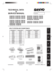
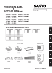
4-Way Air Discharge
Semi-Concealed type
Ceiling-Mounted type
Concealed-Duct type
XH2672R
TH2672R
UH2672R
XH3672R
TH3672R
UH3672R
XH4272R
TH4272R
KH3072R
KH3672R
KHH2672R
THH2672R
THH3672R
Split System Air Conditioner
85464189788001
©SANYO 2006
2
3
Indoor Units
Wall-Mounted type
1
•
INSTRUCTION MANUAL
SANYO Electric Co., Ltd.
Gunma, Japan
06-212 PAC-i_IM_Sec1
4/12/06
7:15 PM
Page 1
Save These Instructions!
RCS-SH80UG
Wall-Mounted type
KH2672R
4-Way Air Discharge
Semi-Concealed type
Ceiling-Mounted type
1
Concealed-Duct type
XH2672R
TH2672R
UH2672R
XH3672R
TH3672R
UH3672R
KH3072R
KH3672R
XH4272R
TH4272R
KHH2672R
THH2672R
THH3672R
Split System Air Conditioner
•
INSTRUCTION MANUAL
06-212 PAC-i_IM_Sec1
4/12/06
7:15 PM
Page 2
Contents
Page
Product Information .......................................................................................... 2
Alert Symbols ................................................................................................... 2
Installation Location .......................................................................................... 3
Electrical Requirements.................................................................................... 3
Safety Instructions ............................................................................................ 3
Names of Parts ................................................................................................. 4
Remote Control Unit ..........................................................................................5
Operation ...........................................................................................................9
Adjusting the Airflow Direction ........................................................................10
Special Remarks .............................................................................................12
Setting the Timer ............................................................................................13
Care and Cleaning ..........................................................................................15
Troubleshooting ...............................................................................................17
Tips for Energy Saving ...................................................................................17
Product Information
If you have problems or questions concerning your Air Conditioner, you will
need the following information. Model and serial numbers are on the
nameplate on the bottom of the cabinet.
Model No.
Serial No.
Date of purchase
Dealer’s address
Phone number
1
Alert Symbols
The following symbols used in this manual, alert you to potentially
dangerous conditions to users, service personnel or the appliance:
This symbol refers to a hazard or unsafe
practice which can result in severe personal
injury or death.
This symbol refers to a hazard or unsafe
practice which can result in personal injury or
product or property damage.
1-2
06-212 PAC-i_IM_Sec1
4/12/06
7:15 PM
Page 3
Installation Location
•
We recommend that this air conditioner be installed properly by
qualified installation technicians in accordance with the Installation
Instructions provided with the unit.
Before installation, check that the voltage of the electric supply in
your home or office is the same as the voltage shown on the
nameplate.
•
• Do not install this air conditioner where there are fumes or
flammable gases, or in an extremely humid space such as a
greenhouse.
• Do not install the air conditioner where excessively high heatgenerating objects are placed.
Avoid:
To protect the air conditioner from heavy corrosion, avoid installing the
outdoor unit where salty sea water can splash directly onto it or in
sulphurous air near a spa.
Electrical Requirements
1.
2.
3.
All wiring must conform to the local electrical codes. Consult your dealer
or a qualified electrician for details.
Each unit must be properly grounded with a ground (or earth) wire
or through the supply wiring.
Wiring must be done by a qualified electrician.
To warm up the system, the power mains
must be turned on at least five (5) hours
before operation. Leave the power mains
ON unless you will not be using this
appliance for an extended period.
Power mains
ON
1
Safety Instructions
•
•
Read this Instruction Manual carefully before using this air
conditioner. If you still have any difficulties or problems, consult
your dealer for help.
The air conditioner is designed to give you comfortable room
conditions. Use this only for its intended purpose as described in
this Instruction Manual.
• Never touch the unit with wet hands.
• Never use or store gasoline or other flammable vapor or liquid near
the air conditioner — it is very dangerous.
• This air conditioner has no ventilator for intaking fresh air from
outdoors. You must open doors or windows frequently when you use
gas or oil heating appliances in the same room, which consume a
lot of oxygen from the air. Otherwise there is a risk of suffocation in
an extreme case.
• Do not turn the air conditioner on and off from the power mains
switch. Use the ON/OFF operation button.
• Do not stick anything into the air outlet of the outdoor unit. This is
dangerous because the fan is rotating at high speed.
• Do not let children play with the air conditioner.
• Do not cool or heat the room too much if babies or invalids are
present.
1-3
06-212 PAC-i_IM_Sec1
4/12/06
7:15 PM
Page 4
Names of Parts
INDOOR UNIT
SEMI-CONCEALED
X type (4-WAY)
WALL-MOUNTED
K type
Air intake
Celling
panel
(optional)
Air outlet
Air outlet Air intake
CEILING-MOUNTED
T type
CONCEALED DUCT
U type
Air outlet
Ceiling
Air intake
Air outlet
(optional)
Air intake
(optional)
REMOTE CONTROL UNITS
(optional)
1
(Wired type:
available for all
indoor units)
System Remote
Controller
1-4
(Wireless type:
available for
X and T)
(Wireless type:
available for U)
NOTE
This illustration is based on the external
appearance of a standard model.
Consequently, the appearance may differ
from that of the air conditioner you have
selected.
06-212 PAC-i_IM_Sec1
4/12/06
7:15 PM
Page 5
Remote Cotrol Unit
•
•
•
With this remote controller, you can operate indoor units up to 8 units.
Once you set your operation conditions, you can operate the units only by pressing the ON/OFF
operation button.
For the U type, the flap position is not shown on the display.
N: SENSOR
J: TIMER
SET button
B: OPERATION lamp
K: TIME
setting
buttons
A: ON/OFF operation
button
G: CHECK
button
C: MODE button
O: VENTILATION
button
D: Temperature
setting buttons
E: FAN SPEED
F: FILTER reset L: SET button I: FLAP button
selector button
button
H: UNIT button
M: CL button
A: ON/OFF operation button
This button is for turning the air conditioner on and off.
B: Operation lamp
This lamp lights when the air conditioner is turned on.
C: MODE button
Use this button to select one of the following five operations:
(AUTO)
(HEAT)
(DRY)
(COOL)
(FAN)
: Used to automatically set cooling or heating operation.
Only for heat pump type
(temperature range: 62 ~ 80 °F)
: Used for normal heating operation.
Only for heat pump type
(temperature range: 60 ~ 86 °F)
: Used for dehumidifying without changing the room temperature.
(temperature range: 64 ~ 86 °F)
: Used for normal cooling operation.
(temperature range: 64 ~ 86 °F)
: Used to run the fan only, without heating or cooling operation.
: Press this button to increase the temperature setting.
: Press this button to decrease the temperature setting.
D: Temperature
setting buttons
E: FAN SPEED selector
button
1
(AUTO)
(HI.)
(MED.)
(LO.)
NOTE
:
:
:
:
The air conditioner automatically decides the fan speed.
High fan speed.
Medium fan speed.
Low fan speed.
When low fan speed is selected and the air conditioner is in cooling
operation at a low outdoor temperature of less than 50°F, the air
conditioner may automatically switch to medium fan speed.
1-5
06-212 PAC-i_IM_Sec1
4/12/06
7:15 PM
Page 6
Remote Control Unit (continued)
F: FILTER reset button
Use this button to reset the filter sign
. The air conditioner has a timer
for the filter and informs you when the filter needs cleaning.
G: CHECK button
This button is used only when servicing the air conditioner.
Do not use the CHECK button for normal operation.
H: UNIT button
When more than one indoor unit is connected, this button is used to
select a unit when adjusting the airflow direction.
If no unit is selected, the airflow direction of all units can be adjusted
concurrently using the FLAP button.
I: FLAP button
(
)
1. Use this button to set the airflow direction to a specific angle.
The airflow direction ( ) is displayed on the remote control unit.
Operation mode
Number of airflow direction settings
(COOL) or (DRY)
(HEAT) or (FAN)
(AUTO)
Cooling mode:
Heating mode:
3
5
3
5
• In the cool mode and dry mode, when the flaps are set in a
downward position, condensation may form and drip around
the vent.
• Do not move the flap with your hands.
This function is available only for models X and T.
NOTE
NOTE
1
(
)
NOTE
NOTE
.
J: TIMER SET button
2. Use this button to make the airflow direction sweep up and down
automatically.
Press this button several times until the (
) symbol appears on
the display.
This function is available only for models X, T and K.
Use this button while the unit is operating to switch between timer
settings:
(OFF Timer)
(OFF Cycle Timer)
(ON Timer)
K: Time setting buttons
:The air conditioner stops after the length of time set.
:The air conditioner after the same set time every time.
:The air conditioner starts after the length of time set.
:Press this button to increase the time.
:Press this button to decrease the time.
L: SET button
Use this button to set the timer.
M: CL button
Use this button to clear the timer setting.
N: Temperature sensor of the
remote controller
While the temperature sensor of the indoor unit usually detects ambient
temperatures, it is also possible to detect temperatures around the
remote controller. For the detail of this functionality, consult your dealer.
(Do not use this functionality for group operation.)
O: VENTILATION button
Use this button when you installed a fan available in the market.
Pressing this button turns on and off the fan.
When turning off the air conditioner, the fan will be also turned off.
While the fan is operating,
will appear in the display. If
is
displayed when pressing the ventilation button, no fans are installed.
1-6
06-212 PAC-i_IM_Sec1
4/12/06
7:15 PM
Page 7
Remote Control Unit (continued)
NOTE
NOTE
1) When two remote control units are being used in one group control*
system,
a) the most recent button that is pressed on any remote control unit
is effective.
b) either a main-remote control unit or a sub-remote control can set
the timer.
*Group control means that maximum up to 8 indoor units can be
concurrently controlled with a remote control unit.
2) If a power failure occurs in timer mode, the time counted up to that
point will be stored in memory.
After power is restored, the timer starts again counting up to the set
time.
1
1-7
06-212 PAC-i_IM_Sec1
4/12/06
7:15 PM
Page 8
Display (Remote Control Unit)
When you first turn on the ON/OFF operation button,
will blink on the display of the remote
controller. During this blinking, the remote controller is verifying units connected. Use the remote
controller, after stops blinking.
B
F
C
I
J
M
G
L
N
K
A
D
O
E
P
H
Description
1
A: When the unit is in the heating standby mode, the
indicator appears. (Refer to the description of the
Special Remarks on page 12.)
B: The currently selected operation mode is displayed.
C: This is displayed when a different operation mode was already selected by another remote control unit and
indicates that the mode cannot be changed.
D:
E:
F:
G:
H:
I:
J:
K:
L:
M:
N:
O:
P:
1-8
When the TIMER SET button is pressed to set the timer, the
indicator flashes.
The currently selected FAN SPEED is displayed.
The currently selected Airflow Direction and SWEEP status are displayed.
This is displayed only when an abnormality occurs within a unit.
When the CHECK button is pressed, the TEST indicator appears.
This is displayed to indicate that the system controller is being used for control.
When
is flashing on the display, the operation is not accepted by the system controller.
This indicates the indoor unit address in case of group control.
Unit No.
1—2
Indoor unit No.
Refrigerant circuit No.
This is displayed when it is time to clean the filter.
When setting the timer, the selected timer mode is displayed.
This indication appears when the temperature is set.
This indication appears when the remote control sensor is used.
This indication appears when the ventilation fan does not operate even if the ventilation button has been
pressed.
This indication appears when the ventilation fan is operating.
06-212 PAC-i_IM_Sec1
4/12/06
7:15 PM
Page 9
Operation
STEP 1, 6
STEP 3
STEP 2
STEP 4
STEP 5
NOTE
To warm up the system, the power mains must be turned on at least five (5) hours before operation.
STEP 1
To start the air conditioner
Press the operation button (ON/OFF button).
STEP 2
Setting the mode
Press the MODE button to select the mode of your choice.
[
NOTE
STEP 3
(AUTO),
(HEAT),
(AUTO) and
(DRY),
(COOL) or
1
(FAN)]
(HEAT) are used only for heat pump type.
Setting the fan speed
Press the FAN SPEED selector button to select the fan speed of your choice.
[
(AUTO),
(HI.),
(MED.) or
(LO.)]
If AUTO is selected, the fan speed switches automatically.
STEP 4
Setting the temperature
Use the
or
button as appropriate to change the temperature setting as desired.
( reduces the temperature, and
increases the temperature.)
STEP 5
Setting the airflow direction
When more than one indoor unit is connected, the UNIT button is used first to select a
unit. Then use the FLAP button to set the airflow direction to a specific angle or to
sweep. (Refer to the description of the remote control unit.)
STEP 6
To stop the air conditioner
Press the operation button (ON/OFF button) again.
1-9
06-212 PAC-i_IM_Sec1
4/12/06
7:15 PM
Page 10
Adjusting the Airflow Direction
I Semi-concealed type
4-way type (X)
This air conditioner is equipped with auto flaps.
You can set the airflow direction to a specific angle or to the sweep
mode using the remote control unit. (Refer to the description of the
remote control unit.)
Do not move the flap with your hands.
I Ceiling mounted type (T)
1
Auto flap
Vertical vane
A. Vertical directions (automatic)
This air conditioner is equipped with an auto flap. You can set the
airflow direction to a specific angle or to the sweep mode using the
remote control unit. (Refer to the description of the remote control unit.)
Do not move the flap with your hands.
B. Horizontal directions (manual)
The horizontal airflow direction can be adjusted manually by moving the
vertical vanes to the left or right.
1 - 10
06-212 PAC-i_IM_Sec1
4/12/06
7:15 PM
Page 11
Adjusting the Airflow Direction (continued)
I Wall mounted type (K)
Indoor unit
A. Vertical directions (automatic)
Confirm that the remote control unit has been turned on. Press the FLAP
button to start the flap moving up and down. If you want to stop the
flap movement and to direct the air in the desired direction, press the
FLAP button again. In the cool mode, don’t direct the flap down more
than 30°, otherwise, condensation may drip on to the floor. Zone “A” is
the recommended flap position for cooling.
Do not move the flap with your hands.
30˚
Zone
“A”
for
cooling
60˚
B. Horizontal directions (manual)
The horizontal airflow can be adjusted manually by moving the vertical
vanes to the left or right.
Zone “B”
for heating
Up
Left
Right
Vertical
vanes
Air outlet
grille
Flap
Down
I Concealed duct type (U)
This air conditioner is not equipped with air outlet parts. These must be
obtained locally. Please refer to the manual of the locally adopted air
outlet parts.
1
1 - 11
06-212 PAC-i_IM_Sec1
4/12/06
7:15 PM
Page 12
Special Remarks
“DRY” Operation
How it works
•
•
•
•
Once the room temperature reaches the level that was set, the unit
repeats the cycle of turning on and off automatically.
In order to prevent the humidity in the room from rising again, the indoor
fan also turns off when the unit stops operating.
The fan speed is set to “LO.” automatically, and cannot be adjusted.
“DRY” operation is not possible if the outdoor temperature is 59 °F or
less.
Heating Operation
Heating performance
•
Because this appliance heats a room by utilizing the heat of the outside
air (heat pump system), the heating efficiency will fall off when the
outdoor temperature is very low. If sufficient heat cannot be obtained with
this heat pump, use another heating appliance in conjunction with this
unit.
Defrosting
•
When the outdoor temperature is low, frost or ice may form on the
outdoor heat exchanger coil, reducing the heating performance.
When this happens, a microcomputer-controlled defrosting system
operates. At the same time, the fan on the indoor unit stops (or runs at
very low speed in some cases) and the
(STANDBY) indicator appears
on the display until defrosting is completed. Heating operation then
restarts after several minutes. (This interval will vary slightly depending
upon the outdoor temperature and the way in which frost forms.)
(STANDBY) on
the display
•
For several minutes after the start of heating operation, the indoor fan will
not start running (or it will run at very low speed in some cases) until the
indoor heat exchanger coil has warmed up sufficiently. This is because a
cold draft prevention system is operating. During this period, the
(STANDBY) indicator remains displayed.
The
indicator remains displayed during defrosting or when the
compressor has been turned off (or when the unit is running at very low
speed) by the thermostat when the system is in the heating mode.
Upon completion of defrosting and when the compressor is turned on
again,
(STANDBY) will turn off automatically as heating operation
resumes.
1
•
•
NOTE
NOTE
Should the power fail while the unit is running
If the power supply for this unit is temporarily interrupted, the unit will
automatically resume operation (once the power is restored) with the
same settings that were in effect before the power was interrupted.
1 - 12
06-212 PAC-i_IM_Sec1
4/12/06
7:15 PM
Page 13
Setting the Timer
OFF timer
Use this mode to turn off the appliance automatically
after the length of time set.
OFF
ON
Set time
OFF cycle
timer
ON timer
OFF
OFF
ON
ON
Set time
Set time
Use this mode to turn the appliance off automatically
after the same set time every time.
Use this mode to start the appliance automatically after
the length of time set.
OFF
ON
Set time
NOTE
NOTE
When two remote control units are being used, either a main-remote control
unit or a sub-remote control unit can be used for timer operations. (Refer to
the description of the remote control unit.)
1
1 - 13
06-212 PAC-i_IM_Sec1
4/12/06
7:15 PM
Page 14
How to set the OFF timer (
)
(Example) To stop the air conditioner after 3.5 hours
Operation
Indication
1. Press the ON/OFF button to start
the air conditioner.
2. Press the TIMER SET button once to
The
and time
$
select the
mode.
indications (hour) flash.
3. Press the
button until 3.5 is
displayed.
Press the
button if the set
time is exceeded.
The
indication
4. Press the SET button to set the
$
disappears and time
OFF timer.
indications (hour) flash.
How to set the OFF cycle timer (
)
(Example) To stop the air conditioner after 3.5 hours every time
Operation
Indication
1. Press the ON/OFF button to start
the air conditioner.
2. Press the TIMER SET button twice to
The
and time
$
select the
mode.
indications (hour) flash.
3. Set the time using the
or
button.
4. Press the SET button to set the
The
indication
$
OFF cycle timer (
).
disappears and time
indications (hour) flash.
NOTE
NOTE
When the OFF cycle timer is set, the unit will stop after 3.5 hours every
operation.
How to set the ON timer (
)
(Example) To start the air conditioner after 10.5 hours
Operation
Indication
1. Press the ON/OFF button to start
the air conditioner.
The
and time
2. Press the TIMER SET button three times
$
indications (hour) flash.
to select the
mode.
3. Press the
button until 10.5 is
displayed.
Press the
button if the set
time is exceeded.
The
and indications
4. Press the SET button to set the
$
shown in the display disappear
ON timer.
and time indications (hour)
flash.
1
NOTE
NOTE
When the ON timer is set, the unit enters the paused state.
How to stop the timer operation
Operation
Push the CL button.
To adjust the timer
$
Indication
The
indication
disappears.
• Each press of the
button increases the timer operation period with half an hour
(30 minutes) step, up to 72.0 hours.
• Each press of the
button decreases the timer operation period with half an hour
(30 minutes) step, down to half an hour.
1 - 14
06-212 PAC-i_IM_Sec1
4/12/06
7:15 PM
Page 15
Care and Cleaning
1. For safety, be sure to turn the air conditioner off and also to
disconnect the power before cleaning.
2. Do not pour water on the indoor unit to clean it. This will damage
the internal components and cause an electric shock hazard.
Air Intake and outlet side
(Indoor Unit)
Clean the air intake and outlet side of the indoor unit with a vacuum
cleaner brush, or wipe them with a clean soft cloth.
If these parts are stained, use a clean cloth moistened with a mild liquid
detergent. When cleaning the air outlet side, be careful not to force the
vanes out of place.
1. Never use solvents or harsh chemicals when cleaning the indoor
unit. Do not wipe plastic parts using very hot water.
2. Some metal edges and the fins are sharp and may cause injury if
handled improperly; be especially careful when you clean these
parts.
3. The internal coil and other components of the outdoor unit must be
cleaned every year. Consult your dealer or service center.
Air filter
The air filter collects dust and other particles from the air and should be
cleaned at regular intervals as indicated in the table below or when the
filter indication ( ) on the display of the remote control unit (wired
type) shows that the filter needs cleaning. If the filter gets blocked, the
efficiency of the air conditioner drops greatly.
Type
X
Period
Six months
T
Six months
K
U
Two weeks
(depending on
filter specifications)
*Concealed duct type (U):
An air filter is not provided with this air conditioner at the time of
shipment. To get clean air and to extend the service life of the air
conditioner, an air filter must be installed in the air intake. For
installation and cleaning the air filter, consult your dealer or service
center.
NOTE
NOTE
How to clean the filter
The frequency with which the filter should be cleaned depends on the
environment in which the unit is used.
1.
2.
Remove the air filter from the air intake grille.
Use a vacuum cleaner to remove light dust. If there is sticky dust on the
filter, wash the filter in lukewarm, soapy water, rinse it in clean water, and
dry it.
1.
Remove the bolt screw on each side out of the latch using a screwdriver.
(After cleaning, be sure to reattach the two bolt screws.)
Slide the two latches of the air intake grille to the direction of the arrow to
open the grille.
Open the air intake grille downward.
How to remove the filter
4-way semi-concealed type
(X):
2.
3.
When cleaning the air filter, never remove the safety chain. If it is
necessary to remove it for servicing and maintenance inside, be sure
to reinstall the safety chain securely (hook on the grille side) after the
work.
1 - 15
1
06-212 PAC-i_IM_Sec1
4/12/06
7:15 PM
Page 16
Care and Cleaning (continued)
How to remove the filter
(continued)
4.
Remove the air filter attached to the air intake grille.
Latch
Safety chain
Air intake
grille
Air filter
Bolt screw
How to remove the filter (continued)
Ceiling-mounted type (T):
1. Remove the bolt screws on the finger-hold using a screw driver. (After
cleaning, be sure to attach the two bolt screws.)
2. Take hold of the finger-hold on the air intake grille and slide it to the rear,
and the grille will open downward.
3. Take hold of the finger-hold on the air filter, first lift it and then pull it
toward you to release it from the catch.
Catch
Finger-hold
Air filter
Air filter finger-hold
Wall-mounted type (K):
Air intake grille
for KHH2672R, KH3072R, KH3672R
1. Move the flap on the air outlet grille to its lowest position with the remote control unit.
2. The filter is disengaged by pushing the tab up gently. Hold the air filter by the tab
at the bottom, and pull downward.
1
1 Push up
then
2 Pull down
Air filter
When replacing the filter, make sure that the FRONT mark is facing you.
Push it up until you hear it click back into position.
for KH2672
1. Move the flap on the air outlet grille to its lowest position with the remote control unit.
2. The filter is disengaged by pushing the tab up gently. Hold the air filter by the tab
at the bottom, and pull downward.
Air intake grille
Air filter
1 - 16
When replacing the filter, make sure that the FRONT mark is facing you.
Push it up until you hear it click back into position.
06-212 PAC-i_IM_Sec1
4/12/06
7:15 PM
Page 17
*Concealed duct type (U):
An air filter is not provided with this air conditioner at the time of shipment. To
get clean air and to extend the service life of the air conditioner, an air filter
must be installed in the air intake. For installation and cleaning the air filter,
consult your dealer or service center.
The frequency with which the filter should be cleaned depends on the
environment in which the unit is used.
NOTE
How to clean the filter
1. Remove the air filter from the air intake grille.
2. Use a vacuum cleaner to remove light dust. If there is sticky dust on the
filter, wash the filter in lukewarm, soapy water, rinse it in clean water, and
dry it.
Troubleshooting
If your air conditioner does not work properly, first check the following points before requesting service. If it still
does not work properly, contact your dealer or a service center.
Trouble
Air conditioner does not
run at all.
Possible Cause
1. Power failure
2. Leakage circuit breaker has tripped.
3. Line voltage is too low.
4. Operation button is turned off.
5. The remote control unit or heat
pump is malfunctioning.
(ERROR and characters such as
E, F, H, L, P, etc., appear on the
display.)
Remedy
1. Restore power.
2. Contact service center.
3. Consult your electrician or dealer.
4. Press the button again.
5. Consult your dealer.
Compressor runs but
soon stops.
1. Obstruction in front of condenser coil 1. Remove obstruction.
Poor cooling (or heating)
performance
1. Dirty or clogged air filter
1. Clean the air filter to improve the
airflow.
2. Heat source or many people in room 2. Eliminate heat source if possible.
3. Doors and/or windows are open.
3. Shut them to keep the heat (or cold)
out.
4. Obstacle near air intake or air
4. Remove it to ensure good airflow.
discharge port
5. Thermostat is set too high for cooling 5. Set the temperature lower (or higher).
(or too low for heating).
6. (Outdoor temperature is too low).
6. (Try to use a back-up heater.)
7. (Defrosting system does not work.)
7. (Consult your dealer.)
“CHECK” is displayed.
1. Trouble in the system
1
1. Contact service center.
Tips for Energy Saving
Avoid
•
•
Do
•
•
NOTE
Do not block the air intake and outlet of the unit. If either is
obstructed, the unit will not work well, and may be damaged.
Do not let direct sunlight into the room. Use sunshades, blinds or curtains.
If the walls and ceiling of the room are warmed by the sun, it will take
longer to cool the room.
Always try to keep the air filter clean. (Refer to “Care and Cleaning.”)
A clogged filter will impair the performance of the unit.
To prevent conditioned air from escaping, keep windows, doors and any
other openings closed.
Should the power fail while the unit is running
If the power supply for this unit is temporarily interrupted the unit will
automatically resume operation (once the power is restored) with the
same settings that were in effect before the power was interrupted.
1 - 17
05-368 PAC-i_IM_Sec2
12/7/05
4:36 PM
Page 1
Save These Instructions!
RCS-SH80UA.WL
RCS-BH80UA.WL
RCS-SH1UA
Wireless Remote Controller for Split
System
•
INSTRUCTION MANUAL
For information on installing the wireless remote controller, refer to the INSTALLATION INSTRUCTIONS
accompanying the outdoor unit.
2
05-368 PAC-i_IM_Sec2
12/7/05
4:36 PM
Page 2
Contents
Page
Product Information .......................................................................................... 2
Alert Symbols ................................................................................................... 2
Installation Location .......................................................................................... 3
Electrical Requirements.................................................................................... 3
Safety Instructions ............................................................................................ 3
Unit Display and Operation Controller .............................................................. 4
Using the Wireless Remote Controller ............................................................. 7
Remote Control Unit ......................................................................................... 9
Display (Wireless Remote Controller)............................................................. 12
Operation ........................................................................................................ 13
Operation without the Wireless Remote Controller ........................................ 14
Special Remarks............................................................................................. 15
Setting the Timer ............................................................................................ 16
Troubleshooting............................................................................................... 18
Tips for Energy Saving ................................................................................... 18
Product Information
If you have problems or questions concerning your Air Conditioner, you will
need the following information. Model and serial numbers are on the
nameplate on the bottom of the cabinet.
Model No.
Date of purchase
Serial No.
Dealer’s address
Phone number
Alert Symbols
2
The following symbols used in this manual, alert you to potentially
dangerous conditions to users, service personnel or the appliance:
This symbol refers to a hazard or unsafe
practice which can result in severe personal
injury or death.
This symbol refers to a hazard or unsafe
practice which can result in personal injury or
product or property damage.
2-2
05-368 PAC-i_IM_Sec2
12/7/05
4:36 PM
Page 3
Installation Location
•
We recommend that this air conditioner be installed properly by
qualified installation technicians in accordance with the Installation
Instructions provided with the unit.
Before installation, check that the voltage of the electric supply in
your home or office is the same as the voltage shown on the
nameplate.
•
• Do not install this air conditioner where there are fumes or
flammable gases, or in an extremely humid space such as a
greenhouse.
• Do not install the air conditioner where excessively high heatgenerating objects are placed.
Avoid:
To protect the air conditioner from heavy corrosion, avoid installing the
outdoor unit where salty sea water can splash directly onto it or in
sulphurous air near a spa.
Electrical Requirements
1.
2.
3.
All wiring must conform to the local electrical codes. Consult your dealer
or a qualified electrician for details.
Each unit must be properly grounded with a ground (or earth) wire
or through the supply wiring.
Wiring must be done by a qualified electrician.
To warm up the system, the power mains
must be turned on at least five (5) hours
before operation. Leave the power mains
ON unless you will not be using this
appliance for an extended period.
Power mains
ON
Safety Instructions
•
•
2
Read this Instruction Manual carefully before using this air
conditioner. If you still have any difficulties or problems, consult
your dealer for help.
The air conditioner is designed to give you comfortable room
conditions. Use this only for its intended purpose as described in
this Instruction Manual.
• Never touch the unit with wet hands.
• Never use or store gasoline or other flammable vapor or liquid near
the air conditioner — it is very dangerous.
• This air conditioner has no ventilator for intaking fresh air from
outdoors. You must open doors or windows frequently when you use
gas or oil heating appliances in the same room, which consume a
lot of oxygen from the air. Otherwise there is a risk of suffocation in
an extreme case.
• Do not turn the air conditioner on and off from the power mains
switch. Use the ON/OFF operation button.
• Do not stick anything into the air outlet of the outdoor unit. This is
dangerous because the fan is rotating at high speed.
• Do not let children play with the air conditioner.
• Do not cool or heat the room too much if babies or invalids are
present.
2-3
05-368 PAC-i_IM_Sec2
12/7/05
4:36 PM
Page 4
Unit Display and Operation
Controller for K, X, and T Types
Remote control
receiver
OPERATION
lamp
TIMER
lamp
STANDBY
lamp
2
Remote control
receiver
NORM.
OFF
OPERATION lamp
TEST
OPER. STDBY TIMER
TIMER lamp
STAND BY lamp
OPERATION lamp
TIMER lamp
STANDBY lamp
Remote control receiver
Operation controller
(housed inside)
2-4
This lamp lights when the appliance is turned on.
This lamp lights when the system is being controlled by the timer.
When the unit is in the heating standby condition, the STANDBY lamp lights.
If the unit is used for cooling only, the STANDBY lamp will not illuminate.
This lamp operates only when an alarm occurs.
This section picks up infrared signals from the wireless remote controller
(transmitter).
You can operate this air conditioner using the operation controller without the
wireless remote controller.
05-368 PAC-i_IM_Sec2
12/7/05
4:36 PM
Page 5
Unit Display and Operation Controller for K, X, and T Types (continued)
To access the operation
controller:
Press on the two latches of the air intake grille with your thumb in the direction of
the arrow to open the grille. And open the air intake grille downward. The
Operation Controller is located in front of the electrical component box.
SERVICING
switches
ON/OFF operation button
SWEEP button
Switch
ADDRESS switch
SERVICING switches
ADDRESS
switch
Switch
SWEEP
button
ON/OFF
operation
button
This button is for turning the air conditioner on and off
(automatically setting cooling or heating operation).
Use this button to make the airflow direction sweep up and down automatically.
Usually set this switch in to the left side.
When operating the air conditioner by using the wireless remote controller, be
sure to match the number on this switch with the number set on the wireless
remote controller.
Otherwise, the remote control will not work.
These switches are used only when servicing the air conditioner.
Do not use these SERVICING switches for normal operation.
2
Turning off the ON/OFF operation button does not
disconnect the power. Use the main power switch to turn off
the power completely.
NORM. position Normal position
OFF position
Select this position when the unit will not be used
for a long period of time.
NORM.
OFF
TEST position
Select this position to operate the unit continuously.
This position should not be selected under normal conditions.
TEST
OPER. STDBY TIMER
2-5
05-368 PAC-i_IM_Sec2
12/7/05
4:36 PM
Page 6
Operation Controller with Receiver (Separated
from Indoor Unit) for U Type
A: Operation controller
B: Remote control receiver
C: ON/OFF operation button
D: SWEEP button
E: SERVICING switches
F: Switch
G: ADDRESS switch
H: OPERATION lamp
I: TIMER lamp
J: STANDBY lamp
K: FILTER lamp
2
A: Operation controller
(separated from indoor unit)
You can operate this air conditioner using the
operation controller without the wireless remote controller.
B: Remote control receiver
This section picks up infrared signals from the wireless remote controller
(transmitter).
C: ON/OFF operation button
This button is for turning the air conditioner on and off (automatically setting
cooling or heating operation).
D: SWEEP button
Use this button to make the airflow direction sweep up and down
automatically.
E: SERVICING switches
These switches are used only when servicing the air conditioner.
Do not use these SERVICING switches for normal operation.
F: Switch
Usually set this switch in to the NORMAL position.
G: ADDRESS switch
When operating the air conditioner by using the wireless remote controller, be
sure to match the number on this switch with the number set on the wireless
remote controller. Otherwise, the remote control will not work.
H: OPERATION lamp
This lamp lights when the appliance is turned on.
I: TIMER lamp
This lamp lights when the system is being controlled by the timer.
J: STANDBY lamp
When the unit is in the heating standby condition, the STANDBY lamp lights.
If the unit is used for cooling only, the STANDBY lamp will not illuminate.
This lamp operates only when an alarm occurs.
K: FILTER lamp
This lamp lights when the filter needs cleaning.
Turning off the ON/OFF operation button does not
disconnect the power. Use the main power switch to turn off
the power completely.
2-6
05-368 PAC-i_IM_Sec2
12/7/05
4:36 PM
Page 7
Using the Wireless Remote
Controller
How to Install Batteries
1.
2.
3.
Press and slide the cover on the back of the wireless remote controller in
the direction of the arrow.
Install two AAA alkaline batteries (LR03). Make sure the batteries point in
the direction marked in the battery compartment.
Press the ACL button, then replace the cover. If you press it, the current
time, ON time, and OFF time are all reset to 0:00.
ACL ACL
button
button
Cover
Cover
•
•
•
•
The batteries last about six months, depending on how much you
use the wireless remote controller.
Replace the batteries when the wireless remote controllerʼs lamp
fails to light, or when the wireless remote controller cannot be
used to change the air conditionerʼs setting.
Use two fresh leak-proof type-AAA alkaline batteries (LR03).
In replacing batteries, follow the instructions as mentioned in the
sub-section ʻʻHow to Install Batteriesʼʼ.
If you do not use the wireless remote controller more than 1
month, take out the batteries.
2
2-7
05-368 PAC-i_IM_Sec2
12/7/05
4:36 PM
Page 8
Using the Wireless Remote Controller (continued)
How to Use the Wireless
Remote Controller
When using the wireless remote controller, always point the unitʼs transmitter
head directly at the air conditionerʼs receiver.
Air conditioner
(Transmitter head)
Remote control
receiver
Wireless remote controller
Wireless Remote Controller
Installation Position
The wireless remote controller can be operated from either a non-fixed position or a wall-mounted position.
To ensure that the air conditioner operates correctly, do not install the wireless
remote controller in the following places:
•
In direct sunlight
•
Behind a curtain or other place where it is covered
•
More than 26 ft away from the air conditioner
•
In the path of the air conditionerʼs airstream
•
Where it may become extremely hot or cold
•
Where it may be subject to electrical or magnetic interference
1.
If Non-fixed Position
Raise the rear plate of the wireless remote controller mounting cradle and
insert the wireless remote controller. The unit can be used either in that
position (placed on a table, for instance) or held in the hand.
Wireless remote
controller
2
Rear plate
Wireless remote controller
mounting cradle
2.
If Wall-mounted Fixed Position
Install the wireless remote controller at a convenient location on a nearby
wall. However, before attaching the wireless remote controller mounting
cradle, check that the wireless remote controller can operate from the
desired wall position.
Secure the installation fitting of the wireless
remote control unit using the screws.
1
Place
here.
Press.
2
Installation fitting of wireless remote control unit
2-8
Procedure for installing the
wireless remote control unit
05-368 PAC-i_IM_Sec2
12/7/05
4:36 PM
Page 9
Remote Cotrol Unit
M: TRANSMITTER
A: ON/OFF operation
button
K: SENSOR
B: MODE button
D: FAN SPEED selector
button
Q: DISPLAY
C: Temperature setting
buttons
G: TIMER SET button
H: Time setting buttons
F: FLAP button
I: SET button
N: ADDRESS button
J: CL button
L: VENTILATION
button
E: FILTER reset button
O: SENSOR button
P: ACL button
A: ON/OFF operation button
This button is for turning the air conditioner on and off.
B: MODE button
Use this button to select one of the following five operations:
(AUTO)
(HEAT)
(DRY)
(COOL)
(FAN)
C: Temperature
setting buttons
D: FAN SPEED selector
button
: Used to automatically set cooling or heating operation.
Only for heat pump type
(temperature range: 62 ~ 80 °F)
: Used for normal heating operation.
Only for heat pump type
(temperature range: 60 ~ 78 °F)
: Used for dehumidifying without changing the room temperature.
(temperature range: 64 ~ 86 °F)
: Used for normal cooling operation.
(temperature range: 64 ~ 86 °F)
: Used to run the fan only, without heating or cooling operation.
: Press this button to increase the temperature setting.
: Press this button to decrease the temperature setting.
(AUTO)
(HI.)
(MED.)
(LO.)
E: FILTER reset button
:
:
:
:
The air conditioner automatically decides the fan speed.
High fan speed.
Medium fan speed.
Low fan speed.
Use this button to reset the filter sign
. The air conditioner has a
timer for the filter and informs you when the filter needs cleaning.
NOTE
NOTE
When low fan speed is selected and the air conditioner is in cooling
operation at a low outdoor temperature of less than 50°F, the air
conditioner may automatically switch to medium fan speed.
2-9
2
05-368 PAC-i_IM_Sec2
12/7/05
4:36 PM
Page 10
Remote Control Unit (continued)
F: FLAP button
(
)
1. Use this button to set the airflow direction to a specific angle.
The airflow direction ( ) is displayed on the remote control unit.
Operation mode
Number of airflow direction settings
(COOL) or (DRY)
(HEAT) or (FAN)
(AUTO)
Cooling mode:
Heating mode:
3
5
3
5
• In the cool mode and dry mode, when the flaps are set in a
downward position, condensation may form and drip around
the vent.
• Do not move the flap with your hands.
This function is available only for models X and T.
NOTE
NOTE
(
)
NOTE
NOTE
2. Use this button to make the airflow direction sweep up and down
automatically.
Press this button several times until the (
) symbol appears on
the display.
This function is available only for models X, T and K.
.
G: TIMER SET button
Use this button while the unit is operating to switch between timer
settings:
(OFF Timer)
(OFF Cycle Timer)
(ON Timer)
H: Time setting buttons
:The air conditioner stops after the length of time set.
:The air conditioner after the same set time every time.
:The air conditioner starts after the length of time set.
:Press this button to increase the time.
:Press this button to decrease the time.
2
I: SET button
Use this button to set the timer.
J: CL button
Use this button to clear the timer setting.
K: SENSOR
A temperature sensor inside the wireless remote controller senses the
room temperature when switched from a temperature sensor inside the
indoor unit.
L: VENTILATION button
Use this button when you installed a ventilation fan available in the
market.
Pressing this button turns on and off the fan.
When turning off the air conditioner, the fan will be also turned off.
While the fan is operating,
will appear in the display.
M: TRANSMITTER
When you press the buttons on the wireless remote controller, the
mark appears in the display to transmit the setting changes to the
receiver in the air conditioner.
N: ADDRESS button
By pressing the ADDRESS button of the remote controller, the display
of the remote controller indicates the current address. If this address
matches with the address of the controller in an indoor unit, the buzzer
will beep. The buzzer will always beep if the indicated address is “ALL”.
If the indicated address is “ALL”, you can operate any of your indoor
units regardless of their setting of controller addresses. Direct the
remote controller to the remote control receiver of the indoor unit you
want to operate and send a signal. (See p.11, How to set the
ADDRESS.)
2 - 10
05-368 PAC-i_IM_Sec2
12/7/05
4:36 PM
Page 11
Remote Control Unit (continued)
O: SENSOR button
Use this button to switch to the temperature sensor of the remote
controller.
The temperature sensor of the air-conditioner is selected at the factory
and the display indicates
under this selection.
NOTE
NOTE
If the remote controller is located near a heat source, such as a space
heater or in direct sunlight, press the SENSOR button to switch to the
sensor on the indoor unit.
P: ACL button
(ALL CLEAR)
Puts the wireless remote controller into pre-operation status. Always
press this button after replacing the batteries.
Q: DISPLAY
Information on the operating conditions is displayed while the wireless
remote controller is switched on. If the unit is turned off, only the mode
that was set previously is still displayed.
NOTE
NOTE
• The wireless remote controller sends the temperature signal to the air conditioner regularly at three
minute intervals. If the signal from the wireless remote controller stops for more than ten minutes
due to the loss of the wireless remote controller or other trouble, the air conditioner will switch to the
temperature sensor which is built into the indoor unit and control the room temperature. In these
cases, the temperature around the wireless remote controller may differ from the temperature
detected at the air conditioner’s position.
DIP switch settings when the wireless remote controller will be used for cooling only
• If the wireless remote controller will be used for cooling only, refer to the figure below and move the switch to position C.
Check that sliding switch 1 is set to “S.”
Set sliding switch 2 to match
the unit type.
SKN
S: Flap type with limit switch
(4-way, ceiling-mounted, wall-mounted)
K: Swing-only type (floor-mounted) installed
N: No-flap type (built-in)
AHC
AHC
A: Heat-pump type
(H: Heat pump with
no auto heat/cool)
C: Cool-only type
Sliding switch 1
ACL (ALL CLEAR)
button
Sensor button
2
Sliding switch 2
2 - 11
05-368 PAC-i_IM_Sec2
12/7/05
4:36 PM
Page 12
How to set the ADDRESS (
)
Setting addresses of indoor units for remote controller
Operation
1. Press the ADDRESS button for
more than four seconds.
2. By each pressing the ADDRESS
button, the indicated address will
change from “ALL” to “1” through “6”
in turn and lap to “ALL”. Adjust the
address switch of an indoor unit you
want to operate to match its address
with the address indicated on the
remote controller.
3. Press the SET button.
NOTE
NOTE
Indication
The display of the remote
controller indicates
,
and the current address
appears and blinks.
The indicated address
stops blinking and remains
for five seconds.
• If the set address on the remote controller matches with the controller address in an indoor unit, the
buzzer will beep.
Address indication
on the remote
controller
Setting of the
address switch of
the controller in an
indoor unit
Match this address with
the address indicated
on the remote
controller.
If the remote
controller indicates
“ALL”:
If the remote
controller indicates
“1”:
If the remote
controller indicates
“2”:
If the remote
controller indicates
“6”:
You can set any
address in the
controller.
NOTE
• To set the address to 1, 2, or 3, switch this “SWITCH” knob to the left;
to set the address to 4, 5, or 6, switch this “SWITCH” knob to the right.
SWITCH
E
2
A
B
D
Display
(Wireless Remote Controller)
C
Description
A: When you press the SENSOR button, the
appears or disappears.
(SENSOR) indicator
B: The currently selected operation mode is displayed.
C: When setting the timer, the selected timer mode is displayed.
D: The currently selected FAN SPEED, FLAP ANGLE and SWEEP status
are displayed.
E: This indicator flashes when you operate the wireless remote controller.
2 - 12
05-368 PAC-i_IM_Sec2
12/7/05
4:36 PM
Page 13
Operation
STEP 1, 6
STEP 2
STEP 3
STEP 4
STEP 5
NOTE
To warm up the system, the power mains must be turned on at least five (5) hours before operation.
STEP 1
To start the air conditioner
Press the operation button (ON/OFF button).
STEP 2
Setting the mode
Press the MODE button to select the mode of your choice.
[
NOTE
STEP 3
(AUTO),
(HEAT),
(AUTO) and
(DRY),
(COOL) or
2
(FAN)]
(HEAT) are used only for heat pump type.
Setting the fan speed
Press the FAN SPEED selector button to select the fan speed of your choice.
[
(AUTO),
(HI.),
(MED.) or
(LO.)]
If AUTO is selected, the fan speed switches automatically.
STEP 4
Setting the temperature
Use the
or
button as appropriate to change the temperature setting as desired.
( reduces the temperature, and
increases the temperature.)
STEP 5
Setting the airflow direction
When more than one indoor unit is connected, the UNIT button is used first to select a
unit. Then use the FLAP button to set the airflow direction to a specific angle or to
sweep. (Refer to the description of the remote control unit.)
STEP 6
To stop the air conditioner
Press the operation button (ON/OFF button) again.
2 - 13
05-368 PAC-i_IM_Sec2
12/7/05
4:36 PM
Page 14
Operation without the Wireless
Remote Controller
STEP 2
STEP 1, 3
If you have lost the wireless remote controller or if it is not working properly, follow the steps below:
2
STEP 1
To start the air conditioner
Press the ON/OFF operation button (automatically setting cooling or heating operation).
STEP 2
Setting the airflow direction
To adjust the airflow direction, press the SWEEP button as appropriate. You can only set
the airflow for all four sides in the same direction, or have each sweep.
STEP 3
To stop the air conditioner
Press the ON/OFF operation button again.
STEP 1
To start the air conditioner
Operate the receiver switch in the
following sequence:
NORMAL
OFF
NORMAL.
(automatically setting auto operation).
STEP 2
2 - 14
To stop the air conditioner
Then turn the switch to OFF.
NORM.
OFF
TEST
OPER. STDBY TIMER
05-368 PAC-i_IM_Sec2
12/7/05
4:36 PM
Page 15
Special Remarks
Heating Operation
Heating performance
•
Because this appliance heats a room by utilizing the heat of the outside
air (heat pump system), the heating efficiency will fall off when the
outdoor temperature is very low. If sufficient heat cannot be obtained with
this heat pump, use another heating appliance in conjunction with this
unit.
Defrosting
•
When the outdoor temperature is low, frost or ice may form on the
outdoor heat exchanger coil, reducing the heating performance.
When this happens, a microcomputer-controlled defrosting system
operates. At the same time, the fan on the indoor unit stops (or runs at
very low speed in some cases) and the
(STANDBY) lamp lights on the
indoor unit until defrosting is completed. Heating operation then restarts
after several minutes. (This interval will vary slightly depending upon the
outdoor temperature and the way in which frost forms.)
(STANDBY) lamp
on the indoor unit
•
For several minutes after the start of heating operation, the indoor fan will
not start running (or it will run at very low speed in some cases) until the
indoor heat exchanger coil has warmed up sufficiently. This is because a
cold draft prevention system is operating. During this period, the
(STANDBY) lamp remains lit.
(STANDBY) lamp remains lit during defrosting or when the
compressor has been turned off (or when the unit is running at very low
speed) by the thermostat when the system is in the heating mode.
Upon completion of defrosting and when the compressor is turned on
again,
(STANDBY) lamp will light off automatically as the heating
operation resumes.
•
•
ADDRESS switch setting
When setting up two or three air conditioners in one room, you can control the
air conditioners correctly by setting the ADDRESS switches of the Operation
Controllers and the Wireless Remote Controllers.
You can control the air conditioners:
1) with one wireless remote controller changing the ADDRESS switch setting
of the wireless remote controller.
2) with each wireless remote controller having the ADDRESS switch set
differently.
NOTE
NOTE
Should the power fail while the unit is running
•
•
If the power supply for this unit is temporarily interrupted the unit will
automatically resume operation (once the power is restored) with the
same settings that were in effect before the power was interrupted.
Be sure to place the wireless remote controller where it can operate the
air conditioner correctly.
2 - 15
2
05-368 PAC-i_IM_Sec2
12/7/05
4:36 PM
Page 16
Setting the Timer
Use this mode to turn off the appliance automatically
after the length of time set.
OFF
OFF timer
ON
Set time
OFF cycle
timer
ON timer
OFF
OFF
ON
ON
Set time
Set time
Use this mode to turn the appliance off automatically
after the same set time every time.
Use this mode to start the appliance automatically after
the length of time set.
OFF
ON
Set time
When two remote control units are being used, either a main-remote control
unit or a sub-remote control unit can be used for timer operations. (Refer to
the description of the remote control unit.)
2
2 - 16
05-368 PAC-i_IM_Sec2
12/7/05
4:36 PM
Page 17
How to set the OFF timer (
)
(Example) To stop the air conditioner after 3.5 hours
Operation
Indication
1. Press the ON/OFF button to start
the air conditioner.
The
and time
2. Press the TIMER SET button once to
$
indications (hour) flash.
select the
mode.
3. Press the
button until 3.5 is
displayed.
Press the
button if the set
time is exceeded.
4. Press the SET button to set the
The
indication
$
OFF timer.
disappears and time
indications (hour) flash.
How to set the OFF cycle timer (
)
(Example) To stop the air conditioner after 3.5 hours every time
Operation
Indication
1. Press the ON/OFF button to start
the air conditioner.
2. Press the TIMER SET button twice to
The
and time
$
select the
mode.
indications (hour) flash.
3. Set the time using the
or
button.
4. Press the SET button to set the
The
indication
$
OFF cycle timer (
).
disappears and time
indications (hour) flash.
NOTE
NOTE
When the OFF cycle timer is set, the unit will stop after 3.5 hours every
operation.
How to set the ON timer (
)
(Example) To start the air conditioner after 10.5 hours
Operation
Indication
1. Press the ON/OFF button to start
the air conditioner.
The
and time
2. Press the TIMER SET button three times
$
indications (hour) flash.
to select the
mode.
3. Press the
button until 10.5 is
displayed.
Press the
button if the set
time is exceeded.
The
and indications
4. Press the SET button to set the
$
shown in the display disappear
ON timer.
and time indications (hour)
flash.
When the ON timer is set, the unit enters the paused state.
NOTE
NOTE
How to stop the timer operation
Operation
Push the CL button.
$
Indication
The
indication
disappears.
To adjust the timer
• Each press of the
button increases the timer operation period with half an hour
(30 minutes) step, up to 72.0 hours.
• Each press of the
button decreases the timer operation period with half an hour
(30 minutes) step, down to half an hour.
2 - 17
2
05-368 PAC-i_IM_Sec2
12/7/05
4:36 PM
Page 18
Troubleshooting
If your air conditioner does not work properly, first check the following points before requesting service. If it still
does not work properly, contact your dealer or a service center.
Trouble
Air conditioner does not
run at all.
Possible Cause
1. Power failure
2. Leakage circuit breaker has tripped.
3. Line voltage is too low.
4. Operation button is turned off.
5. The wireless remote controller or
heat pump is malfunctioning.
6. Batteries in wireless remote
controller have run down.
Remedy
1. Restore power.
2. Contact service center.
3. Consult your electrician or dealer.
4. Press the button again.
5. Consult your dealer.
6. Replace batteries.
Compressor runs but
soon stops.
1. Obstruction in front of condenser coil 1. Remove obstruction.
Poor cooling (or heating)
performance
1. Dirty or clogged air filter
1. Clean the air filter to improve the
airflow.
2. Heat source or many people in room 2. Eliminate heat source if possible.
3. Doors and/or windows are open.
3. Shut them to keep the heat (or cold)
out.
4. Obstacle near air intake or air
4. Remove it to ensure good airflow.
discharge port
5. Thermostat is set too high for cooling 5. Set the temperature lower (or higher).
(or too low for heating).
6. (Outdoor temperature is too low).
6. (Try to use a back-up heater.)
7. (Defrosting system does not work.)
7. (Consult your dealer.)
Lamps on the indoor
unit are flashing.
1. Trouble in wiring system
1. Contact service center.
Tips for Energy Saving
2
Avoid
•
•
Do
•
•
Do not block the air intake and outlet of the unit. If either is
obstructed, the unit will not work well, and may be damaged.
Do not let direct sunlight into the room. Use sunshades, blinds or curtains.
If the walls and ceiling of the room are warmed by the sun, it will take
longer to cool the room.
Always try to keep the air filter clean. (Refer to “Care and Cleaning.”)
A clogged filter will impair the performance of the unit.
To prevent conditioned air from escaping, keep windows, doors and any
other openings closed.
Should the power fail while the unit is running
If the power supply for this unit is temporarily interrupted the unit will
automatically resume operation (once the power is restored) with the
same settings that were in effect before the power was interrupted.
2 - 18
05-368 PAC-i_IM_Sec3
11/24/05
6:17 PM
Page 1
Save These Instructions!
SHA-KC64UG
System Controller for Split System Air
Conditioner
•
INSTRUCTION MANUAL
3
05-368 PAC-i_IM_Sec3
11/24/05
6:17 PM
Page 2
Contents
Page
Product Information .......................................................................................... 2
Alert Symbols ................................................................................................... 2
Installation Location .......................................................................................... 3
Electrical Requirements.................................................................................... 3
Safety Instructions ............................................................................................ 3
How to Use the System Controller ................................................................... 4
I
I
I
I
Functions of buttons ...............................................................................................
Display ....................................................................................................................
How to start group operation ..................................................................................
How to start collective operation.............................................................................
4
7
8
9
Product Information
If you have problems or questions concerning your Air Conditioner, you will
need the following information. Model and serial numbers are on the
nameplate on the bottom of the cabinet.
Model No.
Serial No.
Date of purchase
Dealer’s address
Phone number
Alert Symbols
The following symbols used in this manual, alert you to potentially
dangerous conditions to users, service personnel or the appliance:
This symbol refers to a hazard or unsafe
practice which can result in severe personal
injury or death.
3
This symbol refers to a hazard or unsafe
practice which can result in personal injury or
product or property damage.
3-2
05-368 PAC-i_IM_Sec3
11/24/05
6:17 PM
Page 3
Installation Location
•
We recommend that this system controller be installed properly by
qualified installation technicians in accordance with the Installation
Instructions provided with the system controller.
• Do not install this system controller where there are fumes or
flammable gases, or in an extremely humid space such as a
greenhouse.
• Do not install the system controller where excessively high heatgenerating objects are placed.
Electrical Requirements
1.
2.
All wiring must conform to the local electrical codes. Consult your dealer
or a qualified electrician for details.
Wiring must be done by a qualified electrician.
To warm up the system, the power mains
must be turned on at least five (5) hours
before operation. Leave the power mains
ON unless you will not be using this
appliance for an extended period.
Power mains
ON
Safety Instructions
•
•
Read this booklet carefully before using this system controller. If
you still have any difficulties or problems, consult your dealer for
help.
The air conditioner is designed to give you comfortable room
conditions. Use this only for its intended purpose as described in
the Instruction Manual.
• Never touch the unit with wet hands.
• Never use or store gasoline or other flammable vapor or liquid near
the air conditioner — it is very dangerous.
• The air conditioner has no ventilator for intaking fresh air from
outdoors. You must open doors or windows frequently when you use
gas or oil heating appliances in the same room, which consume a
lot of oxygen from the air. Otherwise there is a risk of suffocation in
an extreme case.
• Do not turn the air conditioner on and off from the power mains
switch. Use the ON/OFF operation button.
• Do not stick anything into the air outlet of the outdoor unit. This is
dangerous because the fan is rotating at high speed.
• Do not let children play with the air conditioner.
• Do not cool or heat the room too much if babies or invalids are
present.
3-3
3
05-368 PAC-i_IM_Sec3
11/24/05
6:17 PM
Page 4
How to Use the System Controller
I Functions of buttons
A: ALL/ZONE/GR
SELECT button
B: ZONE select
button
C: GROUP select
buttons
F: Operation lamp
D: ON button
E: OFF button
G: MODE button
H: Temperature
setting buttons
K: CHECK
button
O: VENTILATION
button
M: SET button
N: CL button
L: CENTRAL CTRL
button
A: ALL/ZONE/GR SELECT button
I: FAN SPEED
button
J: FLAP button
Use this button to select one of the following:
ALL
3
ZONE1
ZONE2
GR1
UNIT
UNIT
GR1
UNIT
UNIT
UNIT
GR2
UNIT
GR2
UNIT
GR3
UNIT
GR3
UNIT
NOTE
NOTE
ALL:
Used for turning all the air conditioners on and off.
ZONE:
Used for turning all the air conditioners of each zone on and
off.
GR:
Used for turning all the air conditioners of each group on and
off.
A maximum of four zones and 16 groups (units) in a zone can be
set.
B: ZONE select button
Use this button to select a zone (1 to 4) to operate individually.
C: GROUP select buttons
Use these buttons to select a group (1 to 16) to operate individually.
3-4
05-368 PAC-i_IM_Sec3
11/24/05
6:17 PM
Page 5
I Functions of buttons
(Continued)
D: ON button
This button is for turning the selected air conditioner on.
E: OFF button
This button is for turning the selected air conditioner off.
F: Operation lamp
This lamp lights when the unit is turned on.
G: MODE button
Use this button to select one of the following five operations:
(AUTO)
(HEAT)
(DRY)
(COOL)
(FAN)
: Used to automatically set cooling or heating operation.
Only for heat pump type
(temperature range: 62 ~ 80 °F)
: Used for normal heating operation.
Only for heat pump type
(temperature range: 60 ~ 78 °F)
: Used for dehumidifying without changing the room temperature.
(temperature range: 64 ~ 86 °F)
: Used for normal cooling operation.
(temperature range: 64 ~ 86 °F)
: Used to run the fan only, without heating or cooling operation.
When the
indication is displayed, you cannot change the
mode from
and
or
to
or
and . To change the
mode, turn off all units once then select the mode again.
NOTE
NOTE
H: Temperature
setting buttons
: Press this button to increase the temperature setting.
: Press this button to decrease the temperature setting.
I: FAN SPEED button
(AUTO)
(HI.)
(MED.)
(LO.)
J: FLAP button
(
)
:
:
:
:
The air conditioner automatically decides the fan speed.
High fan speed.
Medium fan speed.
Low fan speed.
1. Use this button to set the airflow direction to a specific angle.
The airflow direction is displayed on the remote control unit.
Operation mode
Number of airflow direction settings
3
(COOL) or (DRY)
5
(HEAT) or (FAN)
(AUTO)
3
Cooling mode:
5
Heating mode:
• In the cool mode and dry mode, when the flaps are set in a
downward position, condensation may form and drip around
the vent.
• Do not move the flap with your hands.
NOTE
NOTE
(
NOTE
NOTE
NOTE
NOTE
3
This function is available only for models X and T.
)
2. Use this button to make the airflow direction sweep up and down
automatically.
Press this button several times until the (
) symbol appears on
the display.
This function is available only for models X, K and T.
1) The flap setting can be performed only for units that have no remote
controllers.
2) In the ALL or ZONE mode, no flap setting can be performed. If
necessary, you should select the GR mode and use the FLAP button.
3-5
05-368 PAC-i_IM_Sec3
11/24/05
6:17 PM
Page 6
I Functions of buttons
(Continued)
K: CHECK button
This button is used only when servicing the air conditioner.
Do not use the CHECK button for normal operation.
L: CENTRAL
CTRL
button
Use this button to inhibit individual operation by remote controller as
follows:
1: Individual ON/OFF operation is inhibited.
2: Individual ON/OFF, MODE and Temperature setting operation is
inhibited.
3: Individual MODE and Temperature setting operation is inhibited.
4: Individual MODE operation is inhibited.
No indication: Central control is cleared.
(Individual operation)
M: SET button
NOTE
NOTE
This button is used for setting indoor unit’s address when installing the
air conditioner.
Do not use the SET button for normal operation.
N: CL button
Use this button to reset the filter sign .
The air conditioner has the timer for the filter and informs you when the
filter needs cleaning.
O: VENTILATION button
Use this button when you installed a fan available in the market.
Pressing this button turns on and off the fan.
When turning off the air conditioner, the fan will also turned off. While
the fan is operating,
will appear in the display.
If
is displayed when pressing the ventilation button, no fans are
installed.
3
3-6
05-368 PAC-i_IM_Sec3
11/24/05
6:17 PM
Page 7
I Display
H
F
B
G
C
J
E
K
D
I
A
Description
A: When the unit is in the heating standby mode, the
indicator appears.
B: The currently selected operation mode is displayed.
C: The currently selected FAN SPEED, Airflow Direction and SWEEP
settings are displayed.
D: This indication appears when the filter needs cleaning.
E: This indication appears only when an abnormality occurs within a unit.
F: The currently selected mode (ALL, ZONE or GROUP), ZONE number
and GROUP number are displayed.
GROUP number display (no figure: no number registered)
GROUP state display (
selected group)
: registered group,
3
: currently
Operation state display(
: on,
no sign: off,
: alarm)
G: The currently selected central control mode (1, 2, 3 or 4) is displayed.
H: Lights when any of the air conditioners under the system control is
operating; turns off when none of the air conditioners under the system
control is operating. Blinks when any conditioner is operating under
abnormal conditions and its protection functionality is working.
I:
When the
button is pressed for more than four seconds, the TEST
indicator appears.
J: This indication appears when the temperature is set.
K: When turning on the power switch of the system controller,
sign
blinks for a few minutes. While blinking, any controls using the system
controller are inhibited. This is because the system controller is verifying
connected groups.
3-7
05-368 PAC-i_IM_Sec3
11/24/05
6:17 PM
Page 8
How to start group operation
To start group operation
4
Stop
2
1
3
5
9
6
7
8
3
Power
Turn the power supply switch on more than 5 hours before starting operation.
1
Press the SELECT button and select GROUP.
2
Select the ZONE No. including the group to be operated by pressing ZONE button.
3
Select the GROUP No. to be operated by pressing GROUP select buttons
4
Press the ON button.
5
Set the operation mode by pressing the MODE button.
6
Set the desired temperature by pressing one of the temperature setting buttons
7
Set the desired fan speed by pressing the FAN SPEED button.
8
Set the airflow direction to a specific angle or sweep mode.
9
By pressing
, select your desired setting.
Individual: Controls with the remote controller are possible.
Central 1: Individual ON/OFF operation with the remote controller is inhibited.
Central 2: Individual ON/OFF, MODE, and Temp. setting operations with the remote
controller are inhibited.
Central 3: Individual MODE and Temp. setting operations with the remote controller are
inhibited.
Central 4: Individual MODE operation with the remote controller is inhibited.
• Under Central/Individual settings other than listed above, “CENTRAL” is displayed.
AUTO
Operation
Depending on the difference between the temperature setting and the room temperature,
heating and cooling alternate automatically so that a uniform room temperature is maintained.
Stop
Confirming the GROUP No. to be selected, press the OFF button.
NOTE
NOTE
3-8
.
The flap setting can be performed only for units that have no remote
controllers.
.
05-368 PAC-i_IM_Sec3
11/24/05
6:17 PM
Page 9
I How to start collective operation
To start collective operation (ALL or ZONE)
3
Stop
1
4
5
2
7
6
Power
Turn the power supply switch on 5 hours or more before starting operation.
1
Press the SELECT button and select ALL or ZONE.
In case of ZONE collective operation.
2
Select the ZONE No. to be operated by pressing ZONE button.
3
Press the ON button.
4
Set the operation mode by pressing the MODE button.
5
Set the desired temperature by pressing one of the temperature setting buttons
6
Set the desired fan speed by pressing the FAN SPEED button.
7
Select the control mode.
Stop
Confirming the ZONE No. to be selected or ALL indication, press the OFF button.
NOTE
NOTE
.
3
In the ALL or ZONE mode, no flap setting can be performed. If necessary, you
should select the GR mode and use the FLAP button
3-9
05-368 PAC-i_IM_Sec3
3
11/24/05
6:17 PM
Page 10
05-368 PAC-i_IM_Sec3
11/24/05
6:17 PM
Page 11
3
05-368 PAC-i_IM_Sec3
11/24/05
6:17 PM
Page 12
SANYO FISHER COMPANY
A DIVISION OF SANYO NORTH AMERICA CORPORATION
21605 Plummer Street
Chatsworth, CA 91311 U.S.A.
In Canada
SANYO Canada Inc.
300 Applewood Crescent
Concord, Ontario,
L4K 5C7, Canada