1
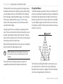
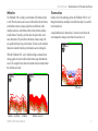
Fishfinder 160C
®
color sonar
owner’s manual
© 2007 Garmin Ltd. or its subsidiaries
Garmin International, Inc.
1200 East 151st Street,
Olathe, Kansas 66062, USA
Tel. (913) 397.8200 or (800) 800.1020
Fax (913) 397.8282
Garmin (Europe) Ltd.
Liberty House
Hounsdown Business Park,
Southampton, Hampshire, SO40 9RB UK
Tel.+44 (0) 870.8501241 (outside the UK)
0808 2380000 (within the UK)
Fax+44 (0) 870.8501251
Garmin Corporation
No. 68, Jangshu 2nd Road,
Shijr, Taipei County, Taiwan
Tel. 886/2.2642.9199
Fax 886/2.2642.9099
All rights reserved. Except as expressly provided herein, no part of this manual may be reproduced, copied, transmitted, disseminated,
downloaded or stored in any storage medium, for any purpose without the express prior written consent of Garmin. Garmin hereby grants
permission to download a single copy of this manual onto a hard drive or other electronic storage medium to be viewed and to print one
copy of this manual or of any revision hereto, provided that such electronic or printed copy of this manual must contain the complete text
of this copyright notice and provided further that any unauthorized commercial distribution of this manual or any revision hereto is strictly
prohibited.
Information in this document is subject to change without notice. Garmin reserves the right to change or improve its products and to make changes in the content
without obligation to notify any person or organization of such changes or improvements. Visit the Garmin Web site (www.garmin.com) for current updates and
supplemental information concerning the use and operation of this and other Garmin products.
Garmin® is a trademark of Garmin Ltd. or its subsidiaries, registered in the USA and other countries. Garmin See-Thru®, and Ultrascrolltm, AutoLocate®, TracBack®,
BlueChart®, and MapSource® are trademarks of Garmin Ltd. or its subsidiaries. These trademarks may not be used without the express permission of Garmin.
March 2007
Part Number 190-00532-00 Rev. D
Printed in Taiwan
Introduction > About This Manual
Introduction
Thank you for choosing the Garmin® Fishfinder 160C. The
Fishfinder 160C is a color sonar that offers many features, including
the following:
• Ultrascroll™, which gives you a much faster update rate on
your Sonar Pages.
• Auto Gain, which allows you to see more fish and structures.
• Whiteline, which helps you to interpret bottom hardness.
• 2x and 4x manual zoom.
• Adjustable keel offset.
• Alarms for shallow water, deep water, low battery, and
suspended target detection.
• NMEA sonar data output.
About This Manual
This manual covers the installation and operation of the Fishfinder
160C. To get the most out of your new Fishfinder, take time to read
this manual and learn the operating procedures for your unit in
detail.
The Introduction contains information about this manual and the
Table of Contents.
The Getting Started section contains general information about
your Fishfinder and sonar.
The Installation Instructions contain the information needed to
properly install and care for the Fishfinder 160C.
The Operating Instructions contain information about the
operation of the Fishfinder 160C.
The Appendix contains information such as specifications, license
requirements and warranty information.
The Index helps you find information quickly.
Fishfinder 160C Owner’s Manual
Introduction > Table of Contents
Table of Contents
Introduction............................................................................i
About This Manual.................................................................... i
Product Registration............................................................... iii
Contact Garmin...............................................................................iii
Caring for the Fishfinder 160C............................................... iii
Caring for the Screen......................................................................iii
Warnings.................................................................................. iv
Important Information............................................................. iv
Getting Started......................................................................1
Understanding the Fishfinder and Sonar............................... 1
Understanding Sonar....................................................................... 1
Understanding the Fishfinder Screen............................................... 1
Using Dual Beam............................................................................. 2
Whiteline......................................................................................... 3
Thermoclines................................................................................... 3
Installing the Fishfinder 160C.............................................4
Packing List.............................................................................. 4
Unit Installation........................................................................ 5
Transducer Installation............................................................ 6
Selecting a Transom Mount Location.............................................. 7
Mounting the Transducer on a Transom.......................................... 8
Mounting the Transducer on a Trolling Motor................................ 9
Testing the Transom Mount Installation........................................ 10
Installing the Wiring Harness................................................ 10
ii
Using the Fishfinder 160C.................................................12
Simulator Mode...................................................................... 12
The Keypad............................................................................. 12
The Fishfinder 160C Display................................................. 13
The Adjustment Bar............................................................... 14
Range............................................................................................. 14
Gain............................................................................................... 14
Scroll.............................................................................................. 14
Zoom.............................................................................................. 15
View............................................................................................... 15
The Setup Menu...................................................................... 15
Alarms........................................................................................... 15
Graph............................................................................................. 16
Numbers......................................................................................... 18
Units............................................................................................... 20
System........................................................................................... 20
Appendix.............................................................................22
Specifications......................................................................... 22
Physical Specifications.................................................................. 22
Power............................................................................................. 22
Sonar.............................................................................................. 22
Limited Warranty.................................................................... 23
Software License Agreement................................................ 24
Declaration of Conformity (DoC).......................................... 24
Index....................................................................................25
Fishfinder 160C Owner’s Manual
Introduction > Product Registration and Caring for the Fishfinder 160C
Product Registration
Caring for the Fishfinder 160C
Use this area to record the serial number (8-digit number located on
the back of the Fishfinder 160C) in case your Fishfinder 160C needs
service. Keep the original sales receipt, or a photocopy, in a safe
place.
Caring for the Screen
Help us better support you by completing our online registration
today! Connect to our Web site at www.garmin.com/registration/.
Serial Number: ___ ___ ___ ___ ___ ___ ___ __
Contact Garmin
Contact Garmin if you have any questions while using your
Fishfinder 160C. In the USA contact Garmin Product Support by
phone: (913) 397-8200 or (800) 800-1020, Monday–Friday, 8 AM–5
PM Central Time; or go to www.garmin.com/support/, and click
Product Support.
The Fishfinder 160C's case is constructed of high-quality materials
and does not require user maintenance except cleaning.
The Fishfinder 160C's lens is coated with a special anti-reflective coating that
is sensitive to skin oils, waxes and abbrasive cleaners. Cleaners containing
amonia, alcohol, abrasives, or anti-grease detergents will harm the antireflective coating. It is important to clean the lens using an eyeglass lens
cleaner (that is specified as safe for anti-reflective coatings) and a clean, lintfree cloth.
Cleaning the Case
Clean the unit’s outer casing (except for the screen) using a cloth dampened
with a mild detergent solution, and then wipe dry. Avoid chemical cleaners and
solvents that may damage plastic components.
Water Immersion
In Europe, contact Garmin (Europe) Ltd. at
+44 (0) 870.8501241 (outside the UK) or
0808 2380000 (within the UK).
The Fishfinder 160C is waterproof to IEC Standard 60529 IPX7. It can
withstand immersion in 1 meter of water for 30 minutes. Prolonged submersion
can cause damage to the unit. After submersion, be certain to wipe and air dry
the unit before reuse.
Tell Us What You Think
Storage
Tell us how you like this manual! Fill out the Product
Documentation Survey. Go to www.garmin.com/contactUs/, and
click Product Documentation Survey.
Fishfinder 160C Owner’s Manual
Do not store the Fishfinder 160C where prolonged exposure to temperature
extremes may occur (such as in the trunk of a car) because permanent damage
may result.
iii
Introduction > Warnings and Important Information
Warnings
WARNING: This product, its packaging, and its components
contain chemicals known to the State of California to cause cancer,
birth defects, or reproductive harm. This Notice is being provided
in accordance with California’s Proposition 65. If you have any
questions or would like additional information, please refer to our
Web site at http://www.garmin.com/prop65.
Important Information
The California Electronic Waste Recycling Act of 2003 requires the recycling
of certain electronics. For more information on the applicability to this product,
see www.erecycle.org.
Hg - lampS inside this product contain mercury
and must be recycled or disposed of according to
local, state, or federal laws.
For more information go to:
www.garmin.com/aboutGarmin/environment/disposal.jsp.
iv
Fishfinder 160C Owner’s Manual
Getting Started > Understanding the Fishfinder and Sonar
Getting Started
Understanding the Fishfinder and Sonar
The Fishfinder 160C is a fully automatic, color sonar unit that allows
you to go out on the water and find fish without having to configure a
lot of settings. However, you can customize each setting as you prefer.
If you have used a Fishfinder before, you might already know how
to interpret the sonar information on the screen, so you can skip this
section. If you have not used a Fishfinder before, you might want to
learn a bit about sonar: what it is, how it works, and what you might
see on the Fishfinder 160C screen. This manual provides a general
understanding of those things that you need to know about sonar that
can help you interpret the screen and find the fish.
These sound waves reflect off of any object that they hit, and then
the waves travel back up to the transducer. These objects could
be fish, branches, the bottom, or any other object that has density
that is different from the water. The transducer receives the sound
wave information, and then sends the information to the Fishfinder.
The Fishfinder shows the information on the screen for you to see
and interpret. The type of transducer and settings that you choose
determine how the information appears on the screen.
Understanding the Fishfinder Screen
Experimentation and experience are the keys to successfully
interpreting your Fishfinder screen. We recommend that you take
your Fishfinder out on familiar water, and spend time learning to
interpret what you see on the Fishfinder 160C screen.
Understanding Sonar
Think of the Fishfinder screen as if you took a picture from the side
of an aquarium in your home. You can see how deep a fish is in
the water (how close it is to the top or bottom), but you cannot tell
where the fish is located horizontally in the water (whether it is near
the front or the back of the aquarium). Remember this when you are
trying to locate exactly where something is in the water.
The transducer sends sound waves down into the water in a cone
shape, similar to a flashlight beam (covering a smaller circular area
at the top and angling out to a larger circular area at the bottom).
The strongest sonar returns appear on your screen as the most
intense solid red. The weaker returns appear as less intense, less
solid colors,with dark blue to black being the weakest.
During installation, you connect your Fishfinder 160C to a
transducer. The transducer uses sound to determine information
about what is in the water beneath your boat. Then the transducer
sends the information to your Fishfinder to be shown on the screen
for you to view and interpret.
Fishfinder 160C Owner’s Manual
Getting Started > Understanding the Fishfinder and Sonar
The bottom of the water is always going to be the strongest signal,
and therefore the bottom is the continuous, intense red line running
across the bottom of the screen. The Fishfinder 160C includes the
latest technology in interpreting bottom signals; it can see through
fish, structures, and thermoclines (see page 3). Even so, large
schools of fish or dense structures close to the bottom can affect
water depth return readings.
Along the top of the screen, you might see a grouping of intense
colors. This area is surface clutter, which can be caused by waves or
any other sonar interference at the surface of the water. Too much
surface clutter can obscure your view of fish. You can turn down the
Gain setting to reduce this surface clutter.
Between the bottom and the surface clutter, you may see suspended
targets. By default, the targets appear as arches.
Note: Suspended target returns might not always appear
as perfect arches, due to the speed, fish orientation, or other
conditions.
You can turn on the Fish Symbols setting if you want to see
suspended targets indicated by fish shapes instead of arches.
Using Dual Beam
A dual beam transducer can transmit a narrow or a wide beam. The
water area covered by the transmitted sound waves is determined by
the transducer beam width and the water depth. The narrow beam
provides crisp detail of what is under your boat, and is very helpful
if you are fishing in deeper water where the beam covers more area
(for example, at a depth of 30 feet, the narrow beam covers the area
of about a 7-foot circle).
Narrow
Beam
Wide
Beam
The wide beam is more helpful in shallow water, because it gives
you a much wider view of objects in the water, including areas
beyond the sides of your boat. At a depth of 30 feet, the wide beam
covers the area of approximately a 20-foot circle.
Fishfinder 160C Owner’s Manual
Getting Started > Understanding the Fishfinder and Sonar
Whiteline
The Fishfinder 160C can help you to determine if the bottom is hard
or soft. When the sonar sound waves are reflected back by the bottom,
a hard bottom returns a stronger signal than a soft bottom. A thin
whiteline indicates a softer bottom while a thick whiteline indicates
a harder bottom. Normally, a red line shows the point where water
meets the bottom. This line follows the bottom contour, along with
any significant objects lying on the bottom. The unit uses the whiteline
function to make the bottom layer information easier to distinguish.
Thermoclines
Garmin’s See-Thru technology allows the Fishfinder 160C to “see”
through thermoclines and helps locate fish where they live; and fish
love thermoclines!
A rough definition of a thermocline is a break in water where the
water temperature changes faster than the water above it.
With the Fishfinder 160C, active whiteline helps accentuate where
strong signals are located, which makes bottom type determination
easier. The example below shows the bottom return with and without
the whiteline activated.
Thermocline
Whiteline Hard Bottom
Soft Bottom
Fishfinder 160C Owner’s Manual
Whiteline Turned Off
Installing the Fishfinder 160C > Packing List
Installing the Fishfinder 160C
Read these instructions before attempting installation. Make sure
you completely understand these instructions before you begin.
When in doubt, seek professional assistance.
Be sure the wiring harness reaches the unit and transducer location
before beginning installation. The Garmin Fishfinder 160C hardware
allows for installation on either the transom or trolling motor. Check
the packing list below. If you are missing any items, contact your
Garmin dealer.
Packing List
A–Fishfinder 160C Sonar Unit (1)
B–Swivel Mount Bracket (1)
C–Swivel Base (1)
D–Mounting Knobs- Short, Long (1ea)
E–Mounting Knob Spacer (1)
F–Transducer With Power Cable (1)
G–Transducer Mount (1)
H–Trolling Motor Mount Gasket (1)
I–5 mm Flat Washers (2)
J–4 x 12 mm Screws (4)
K–10-32 Lock Nut (1)
L–5 x 30 mm Screws (2)
M–10-32 x 1.75 Screw (1)
N–1/4" Cable Clamps (2)
O–Plastic Spacer (1)
P–1/4" Rubber Washer (1)
Q–Cable Tie, 5.6" (4)
R–Cable Tie, 20" (1)
S–Power/Data Cable
(not shown)
H
ENTER
MENU
A
E
I
M
J
D
B
C
N
K
O
L
P
Q
G
F
R
(Cable not shown)
Fishfinder 160C Owner’s Manual
Installing the Fishfinder 160C > Unit Installation
Unit Installation
Choose a location that provides optimal viewing and allows easy
access to the unit’s keypad. Select a mounting surface strong enough
to support the weight of the unit and protect it from excessive
vibration or shock. DO NOT mount the bracket in a location where
the unit is exposed to extreme temperature conditions. When
installing the mounting bracket, be sure to allow room for the
connection and routing of the power cable.
Mounting Holes
Tool List (not included)—drill, screwdriver (Phillips or standard),
three #8 pan-head machine bolts with matching nuts and washers,
and a 5/32" drill bit, OR three #8 pan head self-tapping screws, and
a 1/16" drill bit.
To mount the bracket assembly:
1. Using the swivel base as a template, mark the location of the
three mounting holes.
2. If securing the base with machine bolts, drill three 5/32" holes
at the locations you marked. If securing the base using selftapping screws, drill 1/16" starter holes at the locations you
marked. Generally, starter holes should be no deeper than
half the screw length.
3. Secure the swivel base with three bolts or screws. DO NOT
OVERTIGHTEN.
4. Attach the swivel bracket and secure it with the short knob.
Swivel Base
Short Knob
Swivel Bracket and Base
Fishfinder 160C Owner’s Manual
Installing the Fishfinder 160C > Transducer Installation
To install the unit on the mounting bracket:
1. Align the slot on the back of the unit with the long mounting
knob and slide into place. It may be necessary to adjust the
long knob to spread the bracket arms apart. (Turn counterclockwise to widen the bracket arms, clockwise to tighten.)
2. Adjust the unit angle and tighten the long mounting knob until
snug.
3. Tilt the unit by loosening the long knob on the right side of the
bracket assembly.
4. Rotate the entire bracket by twisting it left or right. (NOTE:
You will hear clicks as you turn the bracket.)
5. Tighten all knobs when the viewing angle you want is
obtained.
Transducer Installation
Once you’ve installed the Fishfinder 160C unit, you must install the
transducer for it to function. The included transducer can be installed
on the transom (see page 7) or on the trolling motor (see page 9).
To assemble the transducer:
1. Insert the rubber washer and plastic spacer in the transducer
at the same time. DO NOT lubricate the rubber washer.
2. Route the cable toward the back and slide the transducer into
the mounting bracket.
3. Place a 5 mm flat washer on the 10-32 x 1.75" screw and
insert the screw through the mounting bracket, spacer, and
rubber washer.
4. Place the remaining 5 mm flat washer on the exposed end,
and install the 10-32 lock nut finger tight. The transducer is
tightened further after installation on the boat.
Fishfinder 160C Owner’s Manual
Installing the Fishfinder 160C > Transducer Installation
Selecting a Transom Mount Location
For your sonar to operate properly, the transducer has to be located
in clean (non-turbulent) water. The transducer should be mounted as
near the center of the boat as possible.
DO NOT cut the transducer lead, this will void your warranty and
may degrade the sonar’s operation.
DO NOT mount the transducer behind strakes, rivet lines, struts,
fittings, water intake, discharge ports, eroding paint, or anything
that creates air bubbles or causes the water to become turbulent.
It is important that the transducer be as close to the center line as
possible in calm, non-turbulent water for optimal performance.
Avoid mounting the transducer in locations where the boat may be
supported during launching, hauling, trailering, or storage.
Mount the transducer away from the path of the prop on single drive
boats. On twin drive boats, mount the transducer between the drives
if possible. Do not mount the transducer directly in the path of the
prop. The transducer can cause cavitation that may degrade the
boat’s performance and damage the prop.
Fishfinder 160C Owner’s Manual
Do not mount the transducer behind
strakes, rivet lines, struts, fittings, water
intakes or discharge ports.
Mount the transducer parallel
with the water line.
Make sure the transducer is below
water level when the boat is on plane
at high speed.
Apply marine sealant to all screw threads to
prevent water from seeping into the transom.
Installing the Fishfinder 160C > Transducer Installation
Mounting the Transducer on a Transom
Drill pilot holes here.
Tool List (not included)—drill, 3/8" wrench or socket, 5/32" and
1/8" drill bits, masking tape, #2 Phillips screwdriver, marine sealant.
Level
1. Position the transom mount at the selected location, making
sure the transducer is parallel with the water line. Mark the
center locations of each hole on the transom mount (see
figures to the right).
2. Using the 5/32" bit, drill the pilot holes approximately
1" (25 mm) deep at the marked locations. To avoid drilling the
holes too deep wrap a piece of tape around the bit 1" from
the point of the bit.
3. Apply marine sealant to the 5 x 30 mm screws. Attach the
transducer to the transom using the 5 x 30 mm screws. Adjust
the transducer to extend beyond the bottom of the transom
approximately 1/8" (3 mm) on fiberglass hulls or 3/8" (10
mm) on aluminum hulls. Adjust the transducer to be aligned
parallel with the water.
4. Tighten the 10-32 locking nut until it touches the mounting
bracket, and then tighten 1/4 turn more (do not overtighten).
Vertical
To mount the transducer on a transom:
Align with transom
bottom. Transducer
should extend 1/8" below
fiberglass hulls or 3/8"
below aluminum hulls.
Bottom of
Transom
Keep parallel with water line.
OK
Note: After you install the transducer on a transom, it is highly
recommended you test the installation (see page 10)
Fishfinder 160C Owner’s Manual
Installing the Fishfinder 160C > Transducer Installation
Mounting the Transducer on a Trolling Motor
To mount the transducer on a trolling motor:
1. Slide the large cable tie through the slot on the transducer
mount with the ridges of the band facing up until equal
lengths extend on both sides of the mount. (NOTE: For cold
water, or heavy timber or debris areas, a metal 4-5" worm
gear clamp is recommended.)
2. Position the mount gasket on the curved top of the transducer
mount.
3. Place the transducer assembly against the motor body of the
trolling motor, with the front of the transducer pointed away
from the trolling motor propeller.
4. Wrap the two ends of the cable tie around the motor body.
Place the pointed end of the cable tie through the fastener
hole on the opposite end and pull it through until it is snug but
not tight. (The cable tie clicks when you pull it.)
5. Position the transducer so that it is parallel with the bottom
when in use, and make sure the gasket is aligned properly.
Pull the cable tie end until tight. Trim off the excess, if
necessary. Tighten the 10-32 locking nut until it touches the
mounting bracket and then tighten 1/4 turn more. (Do not
overtighten.)
Fishfinder 160C Owner’s Manual
6. Route the 30' (9 m) transducer cable using the supplied cable
ties to secure the cable to the motor shaft. You can fill the
forward-facing portion (except the cable tie pocket) of the
transducer mount with sealant to avoid accumulating debris.
Cable tie
Mounting
gasket
Installing the Fishfinder 160C > Wiring Harness Installation
Testing the Transom Mount Installation
Perform this test after you install the Fishfinder. Because you need
water to carry the sonar signal, the Fishfinder does not function
properly with the transducer out of the water. When you place your
boat in the water, check for leaks around the screw holes that are
below the water line. DO NOT leave your boat in the water for an
extended period of time without checking for leaks.
To test the transom mount installation:
1. Begin testing the installation at a slow speed. If the sonar
appears to be working properly, gradually increase the boat’s
speed observing the sonar’s operation. If the sonar signal
suddenly is lost or the bottom return is severely degraded,
note the speed at which this occurs.
2. Return the boat to the speed at which the signal was lost.
Make moderate turns in both directions and see if the signal
improves.
3. If the signal strength improves while turning, adjust the
transducer so that it extends another 1/8" below the transom
of the boat. It might take several adjustments to eliminate the
degradation.
4. If the signal does not improve it may be necessary to move
the transducer to a different location.
Installing the Wiring Harness
The Fishfinder 160C comes with a wiring harness that connects
the unit to power and the transducer with one easy-to-remove
connection. If it is necessary to extend the power wires, use 22
AWG wire. DO NOT cut the transducer cable, because this will void
your warranty. Transducer extension cables are available from your
Garmin Dealer.
If your boat has an electrical system, it may be possible to wire the
unit directly to an unused holder on your current fuse block. If you
are using the boat’s fuse block, remove the in-line fuse supplied with
the unit. You can also wire the unit directly to the battery.
To install the wiring harness:
1.
2.
3.
4.
Install the Red (+) wire on the positive battery terminal.
Install the Black (-) wire on the negative battery terminal.
Install a 2 Amp fuse in the fuse holder (fuse block only).
Align the notches on the cable plug and back of the unit.
Insert the cable into the connector and turn the lock ring
counter-clockwise until it stops.
The Fishfinder 160C outputs NMEA data for: Water Depth, Water
Speed and Water Temperature.
To connect the NMEA output to a NMEA device:
Connect the Blue wire to the Data Input of the NMEA device.
10
Fishfinder 160C Owner’s Manual
Installing the Fishfinder 160C > Wiring Harness Installation
To Transducer
(red) + 10-18 VDC
(black) - Ground (Power/Data)
To Unit
Power
10-18 volts
DC
(blue) Port 1 Data OUT
RXD +
GPS/NMEA
Device
TXD +
(yellow) Alarm Low
Alarm Relay
100ma max
coil current
Wiring Diagram
-
2A
+
Black Red +
Wiring to a Fuse Block
Fishfinder 160C Owner’s Manual
11