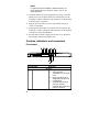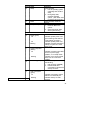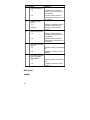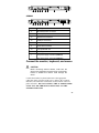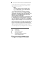
1
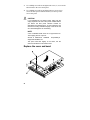
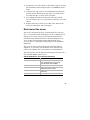
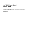
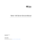
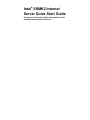
Intel® SRMK2 Internet Server Quick Start Guide A Guide for Technically Qualified Assemblers of Intel Identified Subassemblies/Products Copyright © 1999-2000 Intel Corporation. All rights reserved. No part of this document may be copied, or reproduced in any form, or by any means without prior written consent of Intel. Intel Corporation (Intel) makes no warranty of any kind with regard to this material, including, but not limited to, the implied warranties of merchantability and fitness for a particular purpose. Intel assumes no responsibility for any errors that may appear in this document. Intel makes no commitment to update nor to keep current the information contained in this document. Other brands and names are the property of their respective owners. Order Number: A29364-001 Contents Before you begin 3 Warnings and cautions.................................................... 3 Declaration of the manufacturer or importer .................... 4 Safety compliance .......................................................... 4 Electromagnetic compatibility .......................................... 4 Electromagnetic compatibility notices (SRMK2S)............. 6 FCC/emissions disclaimer – class A (USA)................ 6 Electromagnetic compatibility notices (SRMK2D) ............ 8 FCC/emissions disclaimer – class B (USA)................ 8 FCC Declaration of conformity................................... 9 Unpacking and inspecting 10 Check the accessory kit contents .................................. 10 Inspect the power cord (SRMK2S) ................................ 11 Installing system components 12 Tools and supplies needed............................................ 12 Remove the cover......................................................... 12 Remove the bezel......................................................... 13 Install the SCSI hard drives........................................... 14 Remove the drive carrier ......................................... 14 Install the drive in the carrier ................................... 15 Install the carrier/drive in the drive bay .................... 16 Install the processors .................................................... 17 Preliminary considerations....................................... 17 Install the processor chips ....................................... 19 Install the terminator ............................................... 20 Install the heat sinks................................................ 21 Install the memory (DIMM) boards ................................ 22 Install the add-in (PCI) boards....................................... 24 Remove the retention bracket and rear I/O panels... 24 Remove the riser card............................................. 25 Install the add-in boards in the riser card ................. 26 Install the add-in boards in the server ...................... 27 Replace the cover and bezel......................................... 28 Rack-mount the server.................................................. 29 Powering up 31 AC power cord requirements (SRMK2S) ....................... 31 Controls, indicators, and connectors ............................. 32 Front panel ............................................................. 32 Rear panel .............................................................. 34 Connect the monitor, keyboard, and mouse .................. 35 1 Turn on the video monitor and server............................ 36 Run the power-on self test ............................................ 36 Change the BIOS setup ................................................ 37 Boot from a CD............................................................. 37 Run the SCSISelect utility ............................................. 37 Configure the Adaptec SCSI adapter............................. 38 Accessing the resource CD documents 40 Read and print the documents ...................................... 40 Copy configuration software to diskettes ....................... 41 2 Before you begin Before you perform any of the procedures in this section, read and become thoroughly familiar with the following information. Warnings and cautions Read and adhere to all warnings and cautions in this guide and the documentation referenced and supplied with the server. If the additional instructions supplied with the server are inconsistent with these instructions, contact the supplier to find out how you can ensure that your server meets safety and regulatory requirements. WARNINGS x This guide is intended ONLY for qualified technical personnel with experience installing and configuring servers. x The Power button on the server front panel DOES NOT remove power to the server system. Some circuitry in the server may continue to operate even though the front panel Power button is off. Always disconnect the power cord from the power source or wall outlet before performing any of the procedures in this guide. Failure to do so can result in personal injury or equipment damage. CAUTIONS Perform the procedures in this section only at an electrostatic discharge (ESD) workstation since the server components can be extremely sensitive to ESD. If no such station is available, reduce the risk of electrostatic discharge ESD damage as follows: x Wear an antistatic wrist strap and attach it to a metal part of the server. x Touch the metal on the server chassis before touching the server components. x Keep part of your body in contact with the metal server chassis to dissipate the static charge while handling the components. 3 x Avoid moving around unnecessarily. x Hold the server components boards) only by the edges. x Place the server components on a grounded, static-free surface. Use a conductive foam pad if available but not the component wrapper. x Do not slide the components over any surface. (especially For proper cooling and airflow, the cover must be installed. Operating the server for an extended period without the cover installed can cause overheating and damage the server components. Declaration of the manufacturer or importer We hereby certify that the SRMK2S is in compliance with European Union EMC Directive 89/336/EEC, using standards EN55022 (Class A) and EN55024 and Low Voltage Directive 73/23/EEC, Standard EN60950. Class B certification(s) has been achieved for SRMK2D using the same standards. Safety compliance USA/Canada UL 1950, 3rd Edition/CSA 22.2, No. 950M93, 3rd Edition Europe Low Voltage Directive, 73/23/EEC TUV/GS to EN60950 2nd Edition with Amendments, A1 = A2 + A3 + A4 International CB Certificate and Report to IEC 60950, 3rd Edition including EMKO-TSE (74-SEC) 207/94 and other national deviations Electromagnetic compatibility SRMK2S 4 USA FCC 47 CFR Parts 2 and 15, Verified Class A Limit Canada IC ICES-003 Class A Limit Europe EMC Directive, 89/336/EEC EN55022, Class A Limit, Radiated & Conducted Emissions EN55024, Immunity Standard for Information Technology Equipment EN61000-3-2 Harmonic Currents EN61000-3-3 Voltage Flicker Australia/New Zealand AS/NZS 3548, Class A Limit Japan VCCI Class A ITE (CISPR 22, Class A Limit). IEC 1000-3-2; Harmonic Currents Taiwan BSMI, Class A (CISPR 22) Korea RRL, Class A (CISPR 22) Russia Gost Approval International CISPR 22, Class A Limit SRMK2D USA FCC 47 CFR Parts 2 and 15, Verified Class B Limit Canada IC ICES-003 Class B Limit Europe EMC Directive, 89/336/EEC EN55022, Class B Limit, Radiated & Conducted Emissions EN55024, Immunity Standard for Information Technology Equipment Australia/New Zealand AS/NZS 3548, Class B Limit Japan VCCI Class B ITE (CISPR 22, Class A Limit). Taiwan BSMI, Class B(CISPR 22) Korea RRL, Class B (CISPR22) Russia Gost Approval International CISPR 22, Class B Limit 5 Electromagnetic compatibility notices (SRMK2S) Japan English translation of the notice above: This is a Class A product based on the standard of the Voluntary Control Council for Interference by Information Technology Equipment (VCCI). If this equipment is used in a domestic environment, radio disturbance may arise. When such trouble occurs, the user may be required to take corrective actions. Canada Cet appareil numérique respecte les limites bruits radioélectriques applicables aux appareils numériques de Classe A prescrites dans la norme sur le matériel brouilleur: “Appareils Numériques”, NMB-003 édictée par le Ministre Canadian des Communications. English translation of the notice above: This digital apparatus does not exceed the Class A limits for radio noise emissions from digital apparatus set out in the interferencecausing equipment standard entitled “Digital Apparatus,” ICES-003 of the Canadian Department of Communications. FCC/emissions disclaimer – class A (USA) This equipment has been tested and found to comply with the limits for a Class A digital device, pursuant to Part 15 of the FCC Rules. These limits are designed to provide reasonable protection against harmful interference when the equipment is operating in a commercial environment. This equipment generates, uses, and can radiate radio frequency energy and, if not installed and used in accordance with the instructions, may cause harmful interference to radio communications. Operation of this equipment in a residential area is likely to cause harmful interference. In this case, the user is required to correct the interference at their own expense. If this equipment does cause 6 harmful interference to radio or television reception, which can be determined by turning the equipment off and on; the user is encouraged to try to correct the interference by one or more of the following measures: x Reorient or relocate the receiving antenna. x Increase the separation between the equipment and the receiver. x Connect the equipment into an outlet on a circuit different from that to which the receiver is connected. x Consult the dealer or an experienced radio/TV technician for help. Any changes or modifications not expressly approved by the grantee of this device could void the user’s authority to operate the equipment. The customer is responsible for ensuring compliance of the modified product. Only peripherals (computer input/output devices, terminals, printers, etc.) that comply with FCC Class A limits may be attached to this computer product. Operation with non-compliant peripherals is likely to result in interference to radio and TV reception. All cables used to connect to peripherals must be shielded and grounded. Operation with cables, connected to peripherals that are not shielded and grounded may result in interference to radio and TV reception. Taiwan (BSMI) The BSMI Certification number and the following warning is located on the product safety label which is located visibly on the external chassis. 7 Electromagnetic compatibility notices (SRMK2D) Japan English translation of the notice above: This is a Class B product based on the standard of the Voluntary Control Council for Interference by Information Technology Equipment (VCCI). If this is used near a radio or television receiver in a domestic environment, it may cause radio interference. Install and use the equipment according to the instruction manual. Canada Cet appareil numérique respecte les limites bruits radioélectriques applicables aux appareils numériques de Classe B prescrites dans la norme sur le matériel brouilleur: “Appareils Numériques”, NMB-003 édictée par le Ministre Canadian des Communications. English translation of the notice above: This digital apparatus does not exceed the Class B limits for radio noise emissions from digital apparatus set out in the interferencecausing equipment standard entitled “Digital Apparatus,” ICES-003 of the Canadian Department of Communications. FCC/emissions disclaimer – class B (USA) This equipment has been tested and found to comply with the limits for a Class B digital device, pursuant to Part 15 of the FCC Rules. These limits are designed to provide reasonable protection against harmful interferencein a residential installation. This equipment generates, uses, and can radiate radio frequency energy and, if not installed and used in accordance with the instructions, may cause harmful interference to radio communications. However, there is no guarantee that interference will not occur in a particular installation. If this equipment does cause harmful interference to radio or 8 television reception, which can be determined by turning the equipment off and on; the user is encouraged to try to correct the interference by one or more of the following measures: x Reorient or relocate the receiving antenna. x Increase the separation between the equipment and the receiver. x Connect the equipment into an outlet on a circuit different from that to which the receiver is connected. x Consult the dealer or an experienced radio/TV technician for help. Any changes or modifications not expressly approved by the grantee of this device could void the user’s authority to operate the equipment. The customer is responsible for ensuring compliance of the modified product. Only peripherals (computer input/output devices, terminals, printers, etc.) that comply with FCC Class B limits may be attached to this computer product. Operation with non-compliant peripherals is likely to result in interference to radio and TV reception. All cables used to connect to peripherals must be shielded and grounded. Operation with cables, connected to peripherals that are not shielded and grounded may result in interference to radio and TV reception. NOTE If a Class A device is installed within this system, then the system is to be considered a Class A system. In this configuration, operation of this equipment in a residential area is likely to cause harmful interference. FCC Declaration of conformity SRMK2D This device complies with Part 15 of the FCC Rules. Operation is subject to the following two conditions: (1) This device may not cause harmful interference, and (2) this device must accept any interference received, including interference that may cause undesired operation. 9 For questions related to the EMC performance of this product, contact: Intel Corporation 100 Center Point Circle Columbia, SC 29210 Phone: 1 (800)-INTEL4U or 1 (800) 628-8686 Taiwan (BSMI) The following BSMI Class B EMC Warning along with the BSMI ID number is located on the external left side chassis of the product. Unpacking and inspecting Remove the server from the packaging container and check that the appropriate accessories are included. Inspect the packaging container for evidence of mishandling during transit. If the packaging container is damaged, photograph it for reference. After removing the contents, keep the damaged container and the packing materials. Inspect the server and accessories for damage. If the contents appear damaged, file a damage claim with the carrier immediately. Check the accessory kit contents The accessory kit shipped with the server contains these items: Red Hat Linux 6.2 SBE2 CD-ROM SRMK2 Resource CD-ROM, which contains: x Intel SRMK2 Internet Server Quick Start Guide x Intel SRMK2 Internet Server Product Guide x Intel SRMK2 Internet Server Technical Product Specification x Installation Guide for the Advanced Server Management (ASM) Software for NT and Linux 10 x Advanced Server Management software x Software drivers and utilities Heat sinks (2) AC power cord (SRMK2S only) Front/mid-mount brackets (2) Bracket screws (4) License agreements Late Breaking News If you find that any parts of the accessory kit are missing, contact the supplier immediately. Inspect the power cord (SRMK2S) Verify that the AC power cord is the exact type required in your region. Do not modify or use the supplied power cord if it does not meet the following requirements. x Rating — power cords must be rated for the AC voltage in your region and have a current rating at least 125% of the server current rating. (Refer to the Intel SRMK2 Internet Server Technical Product Specification included in the accessory kit for power requirement information.) x Connector, wall outlet end — power cords must be terminated in a grounding-type male plug designed for use in your region. Cords must have certification marks showing certification by an agency that is acceptable in your region. x Connector, AC power supply end — connector that plugs into the AC receptacle on the server AC power supply must be an IEC 320, sheet C13, type female connector. x Cord length and flexibility — power cord length must be 4.5 meters (14.76 feet) or less and composed of flexible (harmonized HAR) cord or VDE-certified cordage to comply with server safety certifications. 11 NOTE In geographic regions that are susceptible to electrical storms, it is recommended that you plug the server into an AC surge suppressor. Installing system components Perform the following procedures to install the system components required to power up and load an operating system on the server. Before you proceed with the installation procedures, be sure you are thoroughly familiar with the preceding “Before you begin” information. Tools and supplies needed Phillips (cross-head) screwdriver (number 1 and 2 bit) Flat-head screwdriver (3/16-inch) Jumper removal tool or needle nosed pliers Pen or pencil Antistatic wrist strap and conductive foam pad (recommended) Remove the cover A B 12 1. 2. 3. Use a Phillips screwdriver and remove the screw (A) from the front edge of the cover. Grasp the back edge of the cover and simultaneously pull from the back edge and push near the front until the cover slides out from under the edge of the front panel. Grasp the notch (B) in the front center of the cover and lift to remove the cover. Remove the bezel If you are installing the SCSI or slim-line CD-ROM drives, perform this procedure to remove the bezel and allow access to the drive bays. A B 1. 2. 3. 4. Reach behind either end of the bezel (A) and press the plastic clip (B) to release the bezel from the front panel. Gently pull the end of the bezel out just far enough to release the plastic clip from the front panel. Repeat steps 1 and 2 for the other end of the bezel. If you are installing the slim-line CD-ROM drive, follow the instructions in the Intel Slim-line CD-ROM Kit Installation Guide supplied with the kit. 13 5. If you are installing the SCSI hard drives, proceed to the following “Install the SCSI hard drives (SRMK2S and SRMK2D)” procedure. Install the SCSI hard drives The SRMK2 comes ready to accept SCSI drives with SCA connectors. The SRMK2 drive bays are hot-swappable and front removable. Remove the drive carrier F D E C B A 1. 2. 3. 4. 14 Remove the bezel from the front of the server as describe in the previous “Remove the bezel” procedure. Grasp the left edge of the hinged front panel board (A) and swing it away from the front panel to access the SCSI drive bays (B). Press down on the clip (C) at the end of the plastic carrier handle (D) to disengage the clip from the locking slot (E) in the drive bay. Swing the carrier handle outward to disengage the carrier handle latch (F) from the locking slot at the opposite side of the drive bay. 5. Carefully pull on the carrier handle to slide the carrier out of the drive bay. CAUTION Do not operate the server without carriers installed in the SCSI drive bays. Operating with an open drive bay reduces cooling efficiency and can cause overheating which can affect performance or damage components. NOTE A list of validated SCSI drives is at support.intel.com. The mapping at time of print is: Æ Æ Servers Platforms SRMK2 Supported Hardware List Æ Compatibility Æ This path could alter slightly in the future, but the document should be in this relative area. Install the drive in the carrier B B A A 1. Use a Phillips screwdriver and remove the four screws (A) from the carrier slide track. Save the screws. 15 2. 3. 4. Position the drive in the carrier with the connector end of the drive facing the back of the carrier and the drive top facing upward. Align the drive holes (B) with the four mating screw holes in the carrier slide track. Use a Phillips screwdriver and tighten the four screws (A) to secure the carrier to the drive. Install the carrier/drive in the drive bay B A D C 1. 2. With the carrier handle (A) extended in the open position, slide the carrier/drive into the drive bay. Push the carrier handle into the drive bay until the carrier handle latch (B) engages the locking slot and the clip (C) clicks into the locking slot (D) at the opposite side of the drive bay indicating that the drive/carrier is securely locked in the bay. NOTE 16 A list of validated SCSI drives is at support.intel.com. The mapping at time of print is: Æ Æ Servers Platforms SRMK2 Supported Hardware List Æ Compatibility Æ This path could alter slightly in the future, but the document should be in this relative area. Install the processors The serverboard supports either one Intel Pentium III processor in Uniprocessor (UP) mode or two Pentium III processor in Dual Processor (DP) mode. This procedure describes how to install one or both of the appropriate processors on the serverboard. Read the following “Preliminary considerations” information to ensure that you properly install the correct processor(s) on the serverboard. Preliminary considerations x x x x x Due to space constraints, the server will not accommodate the fans and heat sinks normally supplied with replacement processors. Sufficient cooling is provided without a fan mounted on the heat sink. The server ships with two special heat sinks that replace those normally supplied with your boxed processors. The serverboard supports two Pentium III processors that plug into PGA370 socket. The host bus speed (100 MHz or 133 MHz) is automatically selected. When operating in UP mode with one processor installed in the primary PGA370 socket (see the “Install the terminator” information later in this guide). The terminator should already be in place in the second PGA370 socket when you receive the SRMK2. The serverboard supports Pentium III processors with a 133 MHz host bus. The serverboard may not operate reliably or fail to run if a processor with a 133 MHz host is paired with 100 MHz SDRAM. However, processors with a 100 MHz host can be used with either 100 MHz or 133 MHz SDRAM. Select the appropriate processor(s) from the following table of supported processors. 17 Supported processors Processor Type Pentium III L2 Cache Size FSB Speed Speed 256 KB 100 MHz 800 MHz 133 MHz 733 MHz 800 MHz 866 MHz 933 MHz 1.0 GHz CAUTIONS 18 x If you operate the server with two processors installed, be sure that both processors are of the same front side bus (FSB) and MHz rating speed. Dissimilar processors may cause your system to have intermittent problems or most likely prevent your system from booting. x The serverboard supports Pentium III processors with a 133 MHz host bus. Processors with a 100 MHz host bus should be used only with 100 MHz SDRAM. The serverboard may not operate reliably if a processor with a 133 MHz host is paired with 100 MHz SDRAM. Install the processor chips D C A E B 1. 2. 3. 4. 5. Grasp the end of the zero-insertion-force (ZIF) arm (A) and bend it out slightly until it disengages from the socket tab (B). Swing the ZIF arm up until it stops in the straight up position. The processor socket is now unlocked. Face the front of the server and orient the processor chip (C) with the notch (D) in the upper left corner of the processor socket (E). Gently place the processor chip on the socket so that the processor pins mate exactly with the corresponding socket pins. Do not force the processor into the socket since it takes only a slight pressure to bend the pins. With the processor in place, swing the arm (A) down until it snaps into the socket tab (B). NOTE If you install only one processor, a terminator must go in the remaining processor socket. Refer to the following “Install the terminator” procedure. If your server is new, it should come with a terminator preinstalled in the secondary PGA370 socket. 19 Install the terminator If you install only one processor (UP mode), it must go in the primary processor socket, which is the one closest to the DIMM sockets. A terminator is factory-installed in the secondary processor socket. If you want to run the SRMK2 with only one processor, then leave the terminator in the secondary socket. If you choose to install a second processor, then remove the terminator by reversing the following procedure. If there is no terminator installed and you want to run the system with only one processor, contact your supplier to request a new terminator. D C A E B 1. 2. 3. 4. 5. 20 Grasp the end of the zero-insertion-force (ZIF) arm (A) and bend it out slightly until it disengages from the socket tab (B). Swing the ZIF arm up until it stops in the straight up position. The processor socket is now unlocked. Face the front of the server and orient the terminator (C) with the notch (D) in the upper left corner of the processor socket (E). Gently place the terminator on the socket so that the terminator pins mate exactly with the corresponding socket pins. Do not force the terminator into the socket because it takes only a slight pressure to bend the pins. With the terminator in place, swing the arm (A) down until it snaps into the socket tab (B). Install the heat sinks Two heat sinks are supplied in the server accessory kit. These heat sinks are specifically designed to cool the processors you wish to install. Most purchased processors include heat sinks and fans attached. Remove the heat sink and fan supplied with the processors and discard them. Install the heat sinks supplied in the server accessory kit (no heat sink fan required) on the processors as described in the following procedure. Each of the two supplied heat sinks is designed to fit onto a specific processor (either primary or secondary). To differentiate between the two heat sinks, orient one heat sink over the primary processor after the primary processor is installed in the server. If the heat sink aligns correctly over the notches (H and F in the following figure), then you have the correct heat sink for the primary processor; if not, then use the other supplied heat sink. A E B F H C G D I 1. 2. 3. Orient the heat sink (A) so that the thermal grease pad (B) on the heat sink is exactly aligned with the corresponding thermal grease pad (C) on top of the processor chip. With the end of the clamp that has the two slots (D) facing the front of the socket, drop the clamp in the bottom of the heat sink center groove (E). Make sure the end of the clamp with the two slots (D) is positioned just below the top edge of the heat sink and press down on the back of the clamp (F) until it snaps onto the socket tab (G). 21 4. With the front of the clamp below the top edge of the heat sink, press down on the front of the clamp (H) until it snaps onto the socket tab (I). Install the memory (DIMM) boards CAUTIONS x Make sure that the DIMM boards have the correct characteristics. Refer to the supported memory table in the “About the server” section. x Use extreme care when installing a DIMM board. Applying too much pressure or misaligning the board in the socket can damage the sockets or DIMM board edge connectors. The DIMM board edge connectors are keyed and can be inserted only one way. x DIMM boards can be populated in any order, but due to the 25- degree angle of the DIMM sockets there is a potential risk for damage to the DIMM board or the socket. You can reduce the risk of damage by installing the DIMM boards starting with the back socket on the serverboard and moving toward the front (DIMM0 to DIMM3). x Mixing dissimilar metals can cause memory failures that result in data corruption. Since the DIMM board sockets on the serverboard are gold plated, install DIMM boards with goldplated edge connectors. NOTE Memory size can vary between sockets and empty slots between DIMM boards is permitted. The serverboard supports these memory features: x 168-pin SPD DIMM boards with gold-plated contacts. x 133 MHz and 100 MHz registered SDRAM DIMMs, 72-bit ECC, 3.3V only memory. x Single- or double-sided DIMMs in the sizes listed in the following supported memory table. 22 x Registered DIMMs of the following sizes: 64M, 128M, 256M, 512M and 1G for a maximum memory size of 4 GB. Doublestacked DIMMs may only be used if they are within the 4.33 mm maximum thickness imposed by the 25 degree DIMM socket spacing on the serverboard. NOTES All memory components used with this serverboard must comply with the following PC SDRAM specifications: x PC SDRAM Specification (memory component specific) x PC SDRAM Registered DIMM Specification See the Intel SRMK2 Internet Server Technical Product Specification about how to obtain these specifications. A list of validated SCSI drives is at support.intel.com. The mapping at time of print is: Æ Servers Platforms Tested Memory List Æ SRMK2 Æ Compatibility Æ This path could alter slightly in the future, but the document should be in this relative area. 23 B A D C 1. 2. 3. Orient the DIMM board so the key slot (A) in the DIMM board edge connector is properly aligned with the corresponding slot in the mating serverboard socket (B). The connector is keyed to mate in only one direction. Firmly press the DIMM board straight down and all the way into the serverboard socket. Make sure the DIMM board is locked in by pressing the lever (C) on each end of the serverboard socket into the mating notches (D) on each edge of the DIMM board. Install the add-in (PCI) boards The serverboard supports a standard and a low-profile type add-in board. A low-profile board bracket is shorter than the standard board; approximately 3.11 in. (7.9 cm) compared to approximately 4.75 in. (12.06 cm) for the standard board. The low-profile board fits into the right-hand expansion slot (when facing the front of the server) and the standard board fits in the left slot. Remove the retention bracket and rear I/O panels 24 A B 1. 2. Use a Phillips screwdriver and remove the two screws (A) that secure the filler panel retention bracket (B) to the top edge of the server back panel. Use a Phillips screwdriver and remove the screw that secures the filler panel (B) to the expansion slot for the PCI board you are installing. Remove the riser card 25 A B 1. 2. Grasp the riser card at each end (A) and gently rock and lift the riser card until it releases from the serverboard connector (B). Remove the riser card from the serverboard. Install the add-in boards in the riser card A C D B 1. Remove the add-in board from the protective wrapper and set the jumpers or switches according to the manufacturer instructions. 2. Align the add-in board edge connector (A) with the proper riser connector (B). For example: 26 If the add-in board is a standard type (C), the component side faces down and the add-in card edge connector mates with the connector on the left side of the riser card when the riser is pointing toward the back of the server. b. If the add-in board is a low-profile type (D), the component side faces up and the add-in card edge connector mates with the connector on the right side of the riser card. a. 3. Firmly press the add-in board all the way into the mating connector on the riser card. The connectors are keyed to mate in only one direction. Install the add-in boards in the server D E C A 1. 2. B Align the riser card edge connector (A) with the mating riser connector (B) on the serverboard. The connectors are keyed to mate in only one direction. Press the riser card straight down and all the way into the mating connector on the serverboard. 27 3. 4. Use a Phillips screwdriver and tighten the screw (C) to secure the add-in board to the server back panel. Use a Phillips screwdriver and tighten the two screws (D) to secure the filler panel retention bracket (E) to the top of the server back panel. CAUTION If you installed only one add-in board, make sure the empty expansion slot has a filler panel installed before you attach the filler panel retention bracket as described in the following step. An open expansion slot reduces the cooling and EMI integrity of the server that can cause damage due to overheating. NOTE A list of validated SCSI drives is at support.intel.com. The mapping at time of print is: Æ Æ Servers Platforms SRMK2 Supported Hardware List Æ Compatibility Æ This path could alter slightly in the future, but the document should be in this relative area. Replace the cover and bezel D B A C E 28 1. 2. 3. 4. Position the cover on the chassis so the notched edge (A) is facing the front and the slotted sides (B) of the cover inside the chassis frame. Grasp the back edge of the cover and simultaneously push from the back and top until the front edge of the cover slides all the way under the edge (C) of the server front panel. Use a Phillips screwdriver and the screw (D) removed in the previous “Remove the cover” procedure to secure the cover to the chassis. Replace the bezel (E) in the reverse order of the “Remove the bezel” procedure at the front of this guide. Rack-mount the server The server is designed to be front- or mid-mounted in a relay-style rack. Two brackets for rack-mounting the server are shipped as a kit with the server. Refer to the Intel Front/Mid-mount Bracket Kit Installation Guide included in the kit or the Intel SRMK2 Internet Server Product Guide included on the CD-ROM in the server accessory kit (see “Unpacking and inspecting”) for the installation instructions. The server can also be rack-mounted with an optional slide rail adapter kit. If you wish to rack-mount the server with slide rails, contact your customer service representative for ordering details. The following table lists the dimensions and required clearances for a rack-mounted SRMK2 Internet Server. Server dimensions and required clearances Height Width Depth Required front clearance Required rear clearance Required side clearance 4.32 cm (1.70 inches) 42.55 cm (16.75 inches) Fits standard 48.26 cm (19-inch) rack with slide rails installed 60.96 cm (24 inches) 30.48 cm (12 inches) with inlet airflow 35°C/95°F or less 21.60 cm (9 inches) with no airflow restriction N/A 29 WARNINGS x The equipment rack must be anchored to prevent it from tipping when devices are extended on slide assemblies. The anchors must be able to withstand a force of up to 113 kilograms (250 pounds). You must also consider the weight of any other device installed in the rack. x An AC power disconnect for the entire rack unit must be installed. This main disconnect must be readily accessible and labeled as controlling power to the entire unit, not just to the server(s). x To avoid the potential for electrical shock, include a third-wire safety-grounding conductor with the rack installation. If server power cords are plugged into AC outlets that are part of the rack, then you must provide proper grounding for the rack itself. If server power cords are plugged into wall AC outlets, the safety grounding conductor in each power cord provides proper grounding only for the server. You must provide additional grounding for the rack and other devices installed in it. x The server is designed for an AC line voltage source with up to 20 amperes of over-current protection. If the power system for the equipment rack is installed on a branch circuit with more than 20 amperes of protection, you must provide supplemental protection for the server. If more than one server is installed in the rack, the power source for each server must be from a separate branch circuit. CAUTIONS 30 x The operating temperature of the server, when installed in an equipment rack, must not go below 5 °C (41 °F) or rise above 35 °C (95 °F). Extreme fluctuations in temperature can cause a variety of server problems. x The equipment rack must provide sufficient airflow to the front of the server to maintain proper cooling. There must be sufficient ventilation to exhaust at least 1,000 BTU per hour for each server. The rack selected and the ventilation provided must be suitable to the environment in which the server will be used. Powering up This procedure describes how to power up the server. Before proceeding, be sure you are thoroughly familiar with the “Before you begin” information at the front of this guide and the following warning. WARNING Carefully check the AC power cord. If it is not the exact type required in the region where the server will be installed and used, replace the cord with the correct type. Refer to the following “AC power cord requirements” information. AC power cord requirements (SRMK2S) See Inspect the power cord (SRMK2S) before proceeding with this section. 31 NOTE In regions that are susceptible to electrical storms, it is recommended that you plug the server into an AC surge suppressor. 1. 2. 3. 4. Attach the female end of the appropriate AC power cord to the mating AC power receptacle on the server back panel (see the following “Controls, indicators, and connectors” for the location of the AC power receptacle). Plug the male end of the AC power cord into the AC power source or wall outlet. Swing open the bezel door to access the Power switch (see the following “Controls, indicators, and connectors” for the location of the Power switch and indicator). Press the Power switch to apply power to the server and notice that the green LED power indicator is lit. Controls, indicators, and connectors Front panel E F G H I J K L M A B C D 32 Item Name A Power Function Controls When pressed: 1. Turns the power subsystem on if the server is off. 2. Brings the server out of sleep state if the server is in sleep state. 3. And held down for more than four seconds, overrides ACPI mode and power is turned off. Item B Name Sleep C Reset D NMI (Pin hole) Function When pressed: 1. Puts an operating system supporting ACPI mode to sleep. 2. During sleep state, activates operating system. (This server does not have a service mode.) When pressed, resets the server. When pressed: 1. Issues an NMI to the system. 2. Clears the system state when system is hung. Indicators E Power (green) Off On Blinking F System sleep/fault (amber) On Blinking G Hard disk (green) H LAN1 activity/link (green) On Blinking Indicates system power is off. (see “Warnings and cautions” under “Before you begin”). Indicates system power is on. Indicates a system message is waiting or system is in ACPI sleep mode. Indicates a critical system fault, such as a power supply problem, or is in Sleep mode. Indicates a non-critical system fault, such as a hard drive problem. Indicates activity from either of the following: 1. IDE connector (CDROM) 2. External SCSI drive connected to internal SCSI activity connector. Indicates a successful 10/100 Mb link to an Ethernet port. Indicates activity on LAN1 channel. 33 Item Name I LAN1 speed (green) On Off J LAN2 activity/link (green) On Blinking K LAN2 speed (green) On Off L SCSI HDD activity #1 (green) On Off M SCSI HDD activity #2 (green) (SRMK2S and SRMK2D) On Off Rear panel SRMK2S 34 Function Indicates LAN1 controller is detected and configured to run at 100 Mbps. Indicates LAN1 controller is detected and configured to run at 10 Mbps. Indicates a successful 10/100 Mb link to an Ethernet port. Indicates activity on LAN2 channel. Indicates LAN2 controller is detected and configured to run at 100 Mbps. Indicates LAN2 controller is detected and configured to run at 10 Mbps. Indicates activity on SCSI HDD #1. Indicates no activity on SCSI HDD #1. Indicates activity on SCSI HDD #2. Indicates no activity on SCSI HDD #2. A B C D E F G H B C D E F G H I SRMK2D A Item I Description A Mouse/keyboard connectors B Serial port A, COM1 C Dual RJ-45 connectors D USB port connectors E VGA monitor connector F U160 SCSI connector G Low-profile PCI slot H Full length PCI slot I AC power supply connector (SRMK2S) DC power supply connector (SRMK2D) Connect the monitor, keyboard, and mouse CAUTION Before connecting external devices, make sure the server is not plugged into a power source or wall outlet. Failure to observe this caution could damage the server. Connect the monitor, keyboard and mouse to the appropriate connectors on the rear panel of the server. Refer to the “Controls, indicators, and connectors” information for the location of the rear panel connectors. DO NOT CONNECT THE AC POWER CORD UNTIL YOU ARE THROUGH CONNECTING ALL THE EXTERNAL DEVICES. 35 Turn on the video monitor and server Perform the following procedure to turn on the monitor and server. Refer to the “Controls, indicators, and connectors” information for the locations of the controls, indicators, and connectors referenced in this procedure. 1. 2. 3. 4. 5. 6. Make sure all external devices, such as a monitor, keyboard, and mouse, have been connected as described in the previous procedure. If a drive protection card is present in the diskette drive, remove it. Turn on the video monitor. Plug the AC power cord into the AC power connector on the server rear panel and into the AC power source or wall outlet. If the server does not come on when you plug it into the AC power source or wall outlet, press the power button on the server front panel. Verify that the front panel power (green) indicator is lit. After a few seconds, the Power-On Self Test (POST) begins. Run the power-on self test Each time you power on the server, the BIOS executes the power-on self test (POST) which is stored in flash memory. POST discovers, configures, and tests the processors, memory, keyboard, and most installed peripheral devices. The time needed to test memory depends on the amount of memory installed. 1. Turn on your video monitor and server. After a few seconds, POST begins to run and a splash screen is displayed. 2. While the splash screen is displayed, you can: 3. Press F2 to enter the BIOS Setup. See "Changing the BIOS setup.” 4. OR Once the SCSISelect Utility comes up, you can press Ctrl+A to run the Utility. See "Running the SCSISelect utility.” NOTE The server system is shipped with the floppy diskette drive set as the first boot device. Thus, the server tries 36 to boot from a diskette rather than from a CD-ROM. Press F2 to change the boot device priority in the BIOS setup. After POST completes, the system beeps once. If you have an operating system loaded, the operating system takes control of the server system. If no operating system is loaded, the Operating System not found message appears. Change the BIOS setup Changing the BIOS setup is a task for advanced users. For more information about changing BIOS settings, see the Intel SRMK2 Internet Server Product Guide. Boot from a CD During POST, you can change the boot device priority for the current boot process by performing the following procedure: 1. Boot the server (the CD must be in the drive). 2. Press Esc when you see the Intel logo screen at startup. 3. When you see Hit <F2> if you want to run setup at the bottom of the screen during POST, then press F2. When POST completes and the SCSI drives have spun up, the BIOS setup screen will appear. 4. Use the arrow keys to highlight the Boot menu. 5. Use the down arrow key to select 1st Boot Device, then press Enter. A menu appears from which you can select the device that you want the server system to boot from first. For example, if you want the server system to boot from the CD-ROM first, you select ATAPI CDROM and press Enter. 6. Press F10 and then Enter to save your changes and exit the BIOS setup program. Run the SCSISelect utility Use the SCSISelect utility to: x Change default values for the SCSI adapter. x Check and/or change SCSI device settings that may conflict with those of other devices in the server. 37 x Do a low-level format on SCSI devices installed in the server. Each host adapter includes an onboard SCSISelect configuration utility that allows you to configure/view the settings of the host adapters and devices in the server NOTE The system is shipped with the SCSI adapter already set to the default settings. Set up other parameters only if you need specific settings. The system first finds the Adaptec SCSI adapter and displays Adaptec AIC-7899 SCSI BIOS vx.xx where x.xx is the version number of the SCSISelect utility (at this writing, the version number was 2.57). Pressing Ctrl+A at this time allows you to configure the Adaptec SCSI host adapter. If you have more than one SCSI adapter in your system and you enter the configuration menu for one of the host adapters, you can not switch to the other adapter. For example, once you press Ctrl+A to configure the Adaptec SCSI adapter, you have to reboot the system to configure the added SCSI host adapter. If the second SCSI adapter is not an Adaptec 7899 adapter, then you must wait for the SCSISelect utility on the second SCSI adapter to appear on the screen before you press Ctrl+A. If the second SCSI adapter is an Adaptec 7899 adapter, then when you press Ctrl+A you will see a prompt asking which controller you want to configure. Use the following keys to navigate through the menus and submenus. Press Esc To Exit the utility Enter Select an option n p Return to a previous option Move to the next option F5 Switch between color and monochrome F6 Reset to host adapter defaults Configure the Adaptec SCSI adapter 38 The Adaptec adapter has two buses. Select the bus from the following menu. Main Menu You have an AIC 7899 SCSI controller in your system. Move the cursor to the bus:device:channel of the one to be configured and press Enter. F5 - Toggle color/monochrome Bus:Device:Channel 01:046:A 01:046:B After selecting the bus, the following menu is displayed. The internal drives are located on channel B. Menu for each SCSI Channel Each SCSI channel has its own configuration menu similar to this: AIC-7899 at Bus :01h Device :04h Channel B 39 To configure the host adapter or run the SCSI Disk Utilities, select the desired option and press Enter. Press F5 to switch between color and monochrome modes. Option Configure/View Host Adapter Settings SCSI Disk Utilities Comment Press Enter to view the Configuration Menu. Press Enter to view the SCSI Disk Utilities Menu. This menu allows you to format hard disks and/or verify disk media. When you are finished, press Esc (you may need to press Esc several times to get the Exit Menu) and make your selection from the following Exit Menu. Exit Menu Feature Exit Utility? Option Yes No Comment When you finish configuring your SCSI devices, press Esc. Then select Yes and press Enter. When this message appears: Please press any key to reboot Press any key and the server reboots. Accessing the resource CD documents This section describes how to access the documents available on the Resource CD (see the accessory kit contents information in the “Unpacking and inspecting” section). These documents are formatted as .PDF files. Read and print the documents Before you can print the documents, you must have a computer with: x Windows 95 or later installed. x Adobe† Acrobat† Reader installed. x A printer connected. 40 NOTE An online copy of the Intel SRMK2 Internet Server Product Guide is at http://channel.intel.com/isp/ 1. Use your mouse or the up- and down-arrow keys to select the guide. Double click the left mouse button or press Enter to load the .PDF file for the guide. 2. Use your mouse or the tab key to select the .PDF file for the guide. Double click the left mouse button or press an arrow key and Enter to view the .PDF file. 3. Follow the program options and prompts. If you need to access the Help menu, double click on Help or press Alt+h. Copy configuration software to diskettes When you copy software from the Resource CD onto diskettes, device drivers suitable for several different operating systems are copied onto the diskettes. However, your operating system will read only those drivers it can recognize, so you cannot usually check the directory of a diskette that is not formatted for your operating system. Instead, you might see the message disk not formatted, do you want to format it now? The drivers for your operating system are on the diskette and available to load on the server. 41