1
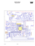
915P/G Combo
MS-7058 (v1.X) ATX Mainboard
G52-M7058X6
i
Manual Rev: 1.0
Release Date: May 2004
FCC-B Radio Frequency Interference Statement
This equipment has been tested and found to comply with the limits for a class B
digital device, pursuant to part 15 of the FCC rules. These limits are designed to
provide reasonable protection against harmful interference when the equipment is
operated in a commercial environment. This equipment generates, uses and can
radiate radio frequency energy and, if not installed and used in accordance with the
instruction manual, may cause harmful interference to radio communications. Operation
of this equipment in a residential area is likely to cause harmful interference, in which
case the user will be required to correct the interference at his own expense.
Notice 1
The changes or modifications not expressly approved by the party responsible for
compliance could void the user’s authority to operate the equipment.
Notice 2
Shielded interface cables and A.C. power cord, if any, must be used in order to
comply with the emission limits.
VOIR LA NOTICE D’INSTALLATION AVANT DE RACCORDER AU RESEAU.
Micro-Star International
MS-7058
This device complies with Part 15 of the FCC Rules. Operation is subject to the
following two conditions:
(1) this device may not cause harmful interference, and
(2) this device must accept any interference received, including interference that
may cause undesired operation
ii
Copyright Notice
The material in this document is the intellectual property of MICRO-STAR
INTERNATIONAL. We take every care in the preparation of this document, but no
guarantee is given as to the correctness of its contents. Our products are under
continual improvement and we reserve the right to make changes without notice.
Trademarks
All trademarks are the properties of their respective owners.
AMD, Athlon™, Athlon™ XP, Thoroughbred™, and Duron™ are registered
trademarks of AMD Corporation.
Intel ® and Pentium® are registered trademarks of Intel Corporation.
PS/2 and OS ® /2 are registered trademarks of International Business Machines
Corporation.
Microsoft is a registered trademark of Microsoft Corporation. Windows® 98/2000/NT/
XP are registered trademarks of Microsoft Corporation.
NVIDIA, the NVIDIA logo, DualNet, and nForce are registered trademarks or trademarks of NVIDIA Corporation in the United States and/or other countries.
Netware ® is a registered trademark of Novell, Inc.
Award® is a registered trademark of Phoenix Technologies Ltd.
AMI® is a registered trademark of American Megatrends Inc.
Kensington and MicroSaver are registered trademarks of the Kensington Technology
Group.
PCMCIA and CardBus are registered trademarks of the Personal Computer Memory
Card International Association.
Revision History
Revision
V1.0
V1.1
V1.2
Revision History
First release for PCB 1.X
with Intel 915P/G & ICH6/ICH6R
First release of multi-language
Version
Add the description of the optional
IEEE 1394 connectors
iii
Date
May 2004
June 2004
July 2004
Technical Support
If a problem arises with your system and no solution can be obtained from the user’s
manual, please contact your place of purchase or local distributor. Alternatively,
please try the following help resources for further guidance.
h Visit the MSI homepage & FAQ site for technical guide, BIOS updates, driver
updates, and other information: http://www.msi.com.tw & http://www.msi.
com.tw/program/service/faq/faq/esc_faq_list.php
h Contact our technical staff at: [email protected]
Safety Instructions
1.
2.
3.
4.
5.
Always read the safety instructions carefully.
Keep this User’s Manual for future reference.
Keep this equipment away from humidity.
Lay this equipment on a reliable flat surface before setting it up.
The openings on the enclosure are for air convection hence protects the equipment from overheating. Do not cover the openings.
6. Make sure the voltage of the power source and adjust properly 110/220V before connecting the equipment to the power inlet.
7. Place the power cord such a way that people can not step on it. Do not place
anything over the power cord.
8. Always Unplug the Power Cord before inserting any add-on card or module.
9. All cautions and warnings on the equipment should be noted.
10. Never pour any liquid into the opening that could damage or cause electrical
shock.
11. If any of the following situations arises, get the equipment checked by a service
personnel:
h The power cord or plug is damaged.
h Liquid has penetrated into the equipment.
h The equipment has been exposed to moisture.
h The equipment has not work well or you can not get it work according to
User’s Manual.
h The equipment has dropped and damaged.
h The equipment has obvious sign of breakage.
12. Do not leave this equipment in an environment unconditioned, storage
temperature above 60 0 C (140 0F), it may damage the equipment.
CAUTION: Danger of explosion if battery is incorrectly replaced.
Replace only with the same or equivalent type recommended by the
manufacturer.
iv
CONTENTS
FCC-B Radio Frequency Interference Statement ....................................................... iii
Copyright Notice ........................................................................................................... iii
Revision History ............................................................................................................ iii
Safety Instructions ...................................................................................................... iv
Technical Support ........................................................................................................ iv
Chapter 1. Getting Started ................................................................................... 1-1
Mainboard Specifications ................................................................................... 1-3
Mainboard Layout ................................................................................................ 1-4
Packing Contents ................................................................................................. 1-5
Chapter 2. Hardware Setup ................................................................................. 2-1
Quick Components Guide .................................................................................... 2-2
Central Processing Unit: CPU .............................................................................. 2-3
Introduction to LGA 775 CPU ..................................................................... 2-3
CPU & Cooler Installation ............................................................................ 2-4
Memory ................................................................................................................ 2-7
Introduction to DDR2 SDRAM ..................................................................... 2-7
Memory Module Population Rules .............................................................. 2-8
Installing DDR2 Modules ............................................................................. 2-8
Power Supply ....................................................................................................... 2-9
ATX 24-Pin Power Connector: ATX1 ......................................................... 2-9
ATX 12V Power Connector: JPW1 ............................................................ 2-9
Back Panel .......................................................................................................... 2-10
Mouse/Keyboard Connector .................................................................... 2-10
VGA Connector (Optional) ....................................................................... 2-10
Serial Port Connector ............................................................................... 2-11
USB Connectors ....................................................................................... 2-11
LAN (RJ-45) Jack ..................................................................................... 2-12
Audio Port Connectors ............................................................................. 2-12
Parallel Port Connector: LPT1 .................................................................. 2-13
Connectors ......................................................................................................... 2-14
Floppy Disk Drive Connector: FDD1 ........................................................ 2-14
Fan Power Connectors: CPUFAN2/SYSFAN1/NBFAN1/PWRFAN1 ....... 2-14
Hard Disk Connectors: IDE1, IDE2 & IDE3
(IDE 2 & IDE3 are optional) ............................................................. 2-15
Serial ATA/Serial ATA RAID Connectors controlled by
Intel ICH6R: SATA1~SATA4 ........................................................... 2-16
v
CD-In Connector: JCD1 ............................................................................ 2-17
Front Panel Connectors: JFP1, JFP2 ....................................................... 2-17
IEEE 1394 Connectors: J1394_1, J1394_2, J1394_3 (Optional) ........... 2-18
Front Panel Audio Connector: JAUD2 ..................................................... 2-18
IrDA Infrared Module Header: JIR1 .......................................................... 2-19
Front USB Connectors: JUSB1 & JUSB2 ................................................ 2-19
Chassis Intrusion Switch Connector: JCI1 ............................................. 2-20
D-Bracket™ 2 Connector: JDB1 .............................................................. 2-20
Jumpers ............................................................................................................. 2-21
Clear CMOS Jumper: JBAT1 .................................................................... 2-21
Slots ................................................................................................................... 2-22
PCI Express Slots ..................................................................................... 2-22
PCI (Peripheral Component Interconnect) Slots ...................................... 2-22
PCI Interrupt Request Routing .................................................................. 2-23
Chapter 3. BIOS Setup ........................................................................................... 3-1
Entering Setup ..................................................................................................... 3-3
Selecting the First Boot Device ................................................................. 3-2
Control Keys ............................................................................................... 3-3
Getting Help ................................................................................................ 3-3
Main Menu ................................................................................................... 3-3
Default Settings .......................................................................................... 3-3
The Main Menu ..................................................................................................... 3-4
Standard CMOS Features ................................................................................... 3-6
Advanced BIOS Features ................................................................................... 3-8
Advanced Chipset Features ............................................................................. 3-10
Integrated Peripherals ....................................................................................... 3-11
Power Management Features .......................................................................... 3-14
PNP/PCI Configurations ..................................................................................... 3-17
H/W Monitor ....................................................................................................... 3-19
Cell Menu ............................................................................................................ 3-21
BIOS Setting Password .................................................................................... 3-25
Load Fail-Safe/Optimized Defaults ................................................................... 3-26
Chapter 4. Introduction to DigiCell .................................................................... 4-1
Main ..................................................................................................................... 4-2
Introduction ................................................................................................. 4-2
H/W Diagnostic .................................................................................................... 4-4
Communication ..................................................................................................... 4-5
Software Access Point ....................................................................................... 4-6
vi
Terminology ................................................................................................. 4-6
Access Point Mode .................................................................................... 4-7
WLAN Card Mode ....................................................................................... 4-8
Live Update .......................................................................................................... 4-9
MEGA STICK ...................................................................................................... 4-10
Basic Function .......................................................................................... 4-10
Non-Unicode programs supported .......................................................... 4-12
Core Center (for Pentium 4 CPU) ...................................................................... 4-14
Left-wing: Current system status ........................................................... 4-15
Right-wing: PC hardware status during real time operation ................. 4-15
Audio Speaker Setting ...................................................................................... 4-16
Power on Agent ........................................................................................ 4-18
Power On .................................................................................................. 4-18
Power Off / Restart .................................................................................. 4-19
Start With .................................................................................................. 4-19
Auto Login ................................................................................................. 4-20
Chapter 5. Introdction to Intel ICH6R SATA RAID ............................................ 5-1
BIOS Configuration .............................................................................................. 5-2
Using the Intel RAID Option ROM ............................................................... 5-2
Installing Software .............................................................................................. 5-8
Install Driver in Windows XP / 2000 .......................................................... 5-8
Installation of Intel Application Accelerator RAID Edition .......................... 5-9
RAID Migration Instructions ............................................................................... 5-14
Create RAID Volume from Existing Disk .................................................. 5-15
Chapter 6. Introduction to VIA VT6410 IDE RAID ............................................. 6-1
Introduction .......................................................................................................... 6-2
RAID 0 (Striping) ......................................................................................... 6-2
RAID Basics ................................................................................................ 6-2
RAID 1 (Mirroring) ....................................................................................... 6-3
RAID 0+1 (Striping/Mirroring) ..................................................................... 6-3
JBOD (Spanning) ........................................................................................ 6-3
BIOS Configuration .............................................................................................. 6-4
Create Disk Array ....................................................................................... 6-5
Delete Disk Array ........................................................................................ 6-8
Create and Delete Spare Hard Drive ......................................................... 6-9
Select Boot Array ..................................................................................... 6-10
View Serial Number of Hard Drive .......................................................... 6-10
Duplicate Critical RAID 1 Array ................................................................ 6-11
vii
Rebuild Broken RAID 0/0+1 Array ........................................................... 6-12
Installing Software ............................................................................................ 6-14
Install Driver in Windows 2000/XP .......................................................... 6-14
Installation of VIA IDE RAID Utility ............................................................ 6-15
Using VIA RAID Tool .......................................................................................... 6-18
Chapter 7. Introduction to CMI9880L Audio Codec ....................................... 7-1
Installing the Audio Codec Driver ....................................................................... 7-2
Software Configuration ...................................................................................... 7-3
Main Setting ................................................................................................ 7-3
Smart Jack .................................................................................................. 7-7
Multi-Stream Function Support & Mixer ..................................................... 7-8
Effect ........................................................................................................ 7-11
Information ................................................................................................ 7-11
viii
Getting Started
Chapter 1. Getting
Started
Getting Started
Thank you for choosing the 915P/G Combo (MS-7058) v1.X
ATX mainboard. The 915P/G Combo mainboard is based on Intel®
915P/G and Intel® ICH6/ICH6R chipset for optimal system efficiency.
Designed to fit the advanced Intel ® Pentium Prescott LGA775
processor, the 915P/G Combo mainboard delivers a high performance and professional desktop platform solution.
1-1
7058 ATX Mainboard
Mainboard Specifications
CPU
h Supports Intel® Pentium 4 Prescott LGA775 processors in LGA775 package.
h Supports up to Pentium 4 3XX, 5XX & 7XX sequence processor or higher speed.
h Supports Intel Hyper-Threading Technology.
(For the latest information about CPU, please visit http://www.msi.com.tw/program/
products/mainboard/mbd/pro_mbd_cpu_support.php)
Chipset
h Intel® 915P/G chipset
- Supports FSB 533/800MHz.
- Supports PCI Express x16 interface.
- Supports DDR2 400/533 memory interface.
- Integrated graphics controller (for 915G only).
h Intel® ICH6/ICH6R chipset
- Hi-Speed USB (USB2.0) controller, 480Mb/sec, up to 8 ports.
- 4 Serial ATA ports with transfer rate up to 1.5Gb/s.
- 1 channel Ultra ATA 100 bus Master IDE controller.
- PCI Master v2.3, I/O APIC.
- ACPI 2.0 Compliant.
- Serial ATA 150 RAID 0, RAID 1 and Matrix RAID (for ICH6R only).
- Integrated AHCI controller (for ICH6R only).
Main Memory
h Supports two DDR1 SDRAM & two DDR2 SDRAM memory modules.
h Supports up to 2GB memory size.
h Supports Dual channel DDR1 & DDR2 memory architecture.
h Supports DDR2 533/400MHz and up.
(For the updated supporting memory modules, please visit http://www.msi.com.tw/
program/products/mainboard/mbd/pro_mbd_trp_list.php.)
Slots
h One PCI Express x16 slot (supports PCI Express Bus specification v1.0a compliant).
h Two PCI Express x1 slots (supports PCI Express Bus specification v1.0a compliant).
h Three 32-bit v2.3 Master PCI bus slots (support 3.3v/5v PCI bus interface).
On-Board IDE
h One Ultra DMA 66/100 IDE controllers integrated in ICH6/ICH6R.
- Supports PIO, Bus Master operation modes.
- Can connect up to Two Ultra ATA drives.
h Serial ATA 150 controller integrated in ICH6/ICH6R.
- Up to 150MB/sec transfer speed.
- Can connect up to four Serial ATA devices.
- Supports AHCI controller with SATA Raid 0, Raid 1 and Matrix Raid (for ICH6R
only).
- Supports SATA hot plug (for ICH6R only).
1-2
Getting Started
VIA6410 IDE Raid Controller (Optional)
h Two Ultra DMA 66/100/133 IDE Controllers.
h Supports RAID 0, 1 and 0+1.
h Connect up to 4 Ultra ATA 133 devices.
On-Board Peripherals
h On-Board Peripherals include:
- 1 floppy port supports 1 FDD with 360K, 720K, 1.2M, 1.44M and 2.88Mbytes
- 1 serial port
- 1 VGA port (for 915G only, Optional)
- 1 parallel port supports SPP/EPP/ECP mode
- 1 Line-In / Line-Out / MIC-In / Rear Speaker Out / Center-Subwoofer Speaker Out
/ SPDIF-Out optical and coaxial audio port
- 8 USB ports (Rear * 4/ Front * 4)
- 1 RJ-45 LAN jack (Optional)
LAN (Optional)
h Realtek® 8100C / 8110S (Optional)
- Integrated Fast Ethernet MAC and PHY in one chip.
- Supports 10Mb/s, 100Mb/s and 1000Mb/s (1000Mb/s for 8100S only).
- Compliance with PCI 2.2.
- Supports ACPI Power Management.
h Marvell 8053 (Optional)
- PCI Express bus Spec 1.0a compliant.
- X1 PCI Express interface with 2.5 GHz signaling.
- 10/100/1000 IEEE 802.3 compliant.
Audio
h Azalia link controller integrated in Intel® ICH6/ICH6R chipset.
h 8-channel audio codec CMedia CMI9880L.
- Compliance with Azalia 1.X Spec.
- Support Multi-Streaming function.
- Support Universal Audio Jack (only Front Audio Jack).
BIOS
h The mainboard BIOS provides “Plug & Play” BIOS which detects the peripheral
devices and expansion cards of the board automatically.
h The mainboard provides a Desktop Management Interface (DMI) function which
records your mainboard specifications.
Mounting and Dimension
h ATX Form Factor: 24.4 cm (W) x 30.5 cm (L)
h 9 mounting holes
1-3
7058 ATX Mainboard
Mainboard Layout
JC11
CPUFAN1
JIR11
Winbo nd
W83 627 TH F
Top : mouse
Bottom : k eyboard
FDD1
DIMM 4
DIMM 1
Bottom :
COM A
VGA port (Optiona l)
DIMM 2
DIMM 3
Top : Pa ra llel Port
T: SPDIFO ut
B:USB port
ATX1
JPW1
T: LAN jac k
B: USB ports
Intel
915P/G
T: Line-In
M: Line-Out
B: Mic
T:RS-Out
M:CS -O ut
B:SPDIF Out
NBFAN1
IDE1
PCI_E1
PCI 1
SATA3
ICH6/
ICH6R
SATA4
PCI_E3
SATA1
BATT
+
BIOS
SATA2
JBAT1
PCI_E2
JCD1
SYSFAN1
IDE 2
PCI 2
CMI
98 80L
IDE 3
VIA
VT641 0
PCI 3
JAUD1
J1394_2
(Optional)
JUSB1
JUSB2
JDB1 JFP2
JFP1
915P/G Combo (MS-7058) v1.X ATX Mainboard
1-4
Getting Started
Packing Contents
MSI motherboard
MSI Driver/Utility CD
SATA Cable *2
Power Cable
D-Bracket 2
(Optional)
Standard Cable for
IDE Devices
User’s Guide
Back IO Shield
Standard Cable for
Floppy Disk
1-5
Hardware Setup
Chapter 2. Hardware Setup
Hardware Setup
This chapter tells you how to install the CPU, memory modules,
and expansion cards, as well as how to setup the jumpers on the
mainboard. Also, it provides the instructions on connecting the peripheral devices, such as the mouse, keyboard, etc.
While doing the installation, be careful in holding the components and follow the installation procedures.
2-1
MS-7058 ATX Mainboard
Quick Components Guide
JPW1, p.2-9
CPUFAN1, p.2-9
NBFAN1, p.2-9
DDR DIMMs, p.2-7
JCI1, p.2-20
JIR1, p.2-19
FDD1, p.2-14
Back Panel
I/O, p.2-10
ATX1, p.2-9
PCI Express x16,
p.2-22
IDE1, p.2-15
JCD1, p.2-18
PCI Slots 1~3,
p.2-22
JAUD1, p.2-18
BATT
+
JBAT1, p.2-22
PCI Express x1,
p.2-22
PWRFAN1, p.2-14
SYSFAN1, p.2-14
SATA1~SATA4,
p.2-16
IDE2, IDE3,
p.2-15
JFP1, p.2-17
JFP2, p.2-17
JDB1, p.2-20
J1394_1~J1934_3,
p.2-18
2-2
JUSB1, JUSB2, p.2-19
Hardware Setup
Central Processing Unit: CPU
The mainboard supports Intel® Pentium 4 Prescott processor. The mainboard
uses a CPU socket called LGA775. When you are installing the CPU, make sure to
install the cooler to prevent overheating. If you do not have the CPU cooler,
contact your dealer to purchase and install them before turning on the computer.
For the latest information about CPU, please visit http://www.msi.com.tw/
program/products/mainboard/mbd/pro_mbd_cpu_support.php.
MSI Reminds You...
Overheating
Overheating will seriously damage the CPU and system, always make
sure the cooling fan can work properly to protect the CPU from
overheating.
Replacing the CPU
While replacing the CPU, always turn off the ATX power supply or
unplug the power supply’s power cord from grounded outlet first to
ensure the safety of CPU.
Overclocking
This motherboard is designed to support overclocking. However, please
make sure your components are able to tolerate such abnormal setting,
while doing overclocking. Any attempt to operate beyond product specifications is not recommended. We do not guarantee the damages
or risks caused by inadequate operation or beyond product
specifications.
Introduction to LGA 775 CPU
The pin-pad side of LGA 775
CPU.
Alignment Key
Yellow triangle is the Pin 1 indicator
The surface of LGA 775 CPU.
Remember to apply some silicone heat transfer compound on
it for better heat dispersion.
Alignment Key
Yellow triangle is the Pin 1 indicator
2-3
MS-7058 ATX Mainboard
CPU & Cooler Installation
When you are installing the CPU, make sure the CPU has a cooler attached on the top to prevent overheating. If you do not have the cooler, contact
your dealer to purchase and install them before turning on the computer. Meanwhile,
do not forget to apply some silicon heat transfer compound on CPU before installing
the heat sink/cooler fan for better heat dispersion.
Follow the steps below to install the CPU & cooler correctly. Wrong installation
will cause the damage of your CPU & mainboard.
1. The CPU has a land side cover on the
bottom to protect the CPU contact from
damage. Rotate it to make the pin 1
indicator (yellow triangle) in the rightbottom corner.
2. Take out the accompanying CPU Clip
and rotate it for the same direction
as the CPU (Pin 1 indicator, the red
triangle is in the left-bottom corner).
land side cover
3. Align the 3 points (the Pin 1 indicator
and the two alignment keys) of both
the CPU and the CPU Clip, and use your
4 fingers to push the CPU Clip down to
clip them (the CPU clip is up and the
CPU is down) together.
4. T h e l a n d s i d e c o v e r n o w i s
removed.
MSI Reminds You...
1. Confirm if your CPU cooler is firmly installed before turning on your
system.
2. Do not touch the CPU socket pins to avoid damaging.
3. The availability of the CPU land side cover depends on your CPU
packing.
2-4
Hardware Setup
5. The CPU has a plastic cap on it to
protect the contact from damage.
Before you have installed the CPU,
always cover it to protect the socket
pin.
6. Remove the cap from lever hinge side
(as the arrow shows).
7. The pins of socket reveal. Then lift
up the load lever.
8. Lift the load lever up and open the
load plate.
9. Correctly align the red triangle of
CPU clip with the CPU chamfer, the
red arrow with the left-side socket
edge, and the red spot to the hook
of the socket.
10. Put the whole module onto the CPU
socket.
2-5
MS-7058 ATX Mainboard
11. Push down the CPU hardly to install
the CPU into the socket housing
frame.
12. Visually inspect if the CPU is seated
well into the socket, then remove the
CPU Clip with 2 fingers. Then cover
the load plate onto the package.
13. Press down the load lever lightly
onto the load plate, and then secure the lever with the hook under
retention tab.
14. Align the holes on the mainboard with
the cooler. Push down the cooler until
its four clips get wedged into the holes
of the mainboard.
15. Press the four hooks down to fasten the cooler. Then rotate the locking switch (refer to the correct direction marked on it) to lock the
hooks.
16. Turn over the mainboard to confirm
that the clip-ends are correctly
inserted.
locking
switch
MSI Reminds You...
1. Check the information in PC Health Status of H/W Monitor in BIOS
(refer to p.3-20 for details) for the CPU temperature.
2. Whenever CPU is not installed, always protect your CPU socket pin
with the plastic cap covered (shown in Figure 1) to avoid damaging.
3. Please note that the mating/unmating durability of the CPU is 20 cycles.
Therefore we suggest you do not plug/unplug the CPU too often.
2-6
Hardware Setup
Memory
The mainboard provides 2 slots for 184-pin DDR1 DIMM (Double In-Line Memory
Module) modules and 2 slots for 240-pin DDR2 DIMM, which supports the memory
size up to 2GB.
Since DDR2 modules are not interchangeable with DDR1 and the DDR2 standard is not backward compatible, you should always install DDR2 memory module in
DDR2 slot (DIMM1 & DIMM3), and DDR1 memory module in DDR1 slot (DIMM2 & DIMM4).
Wrong installation may cause damage of mainboard. Meanwhile, you are not able to
boot up your system if you install DDR1 & DDR2 memory modules simultaneously.
For the updated supporting memory modules, please visit http://www.msi.
com.tw/program/products/mainboard/mbd/pro_mbd_trp_list.php.
DIMM1~DIMM4
(from left to right)
DIMM1 & DIMM3 are for DDR2 memory module
DIMM2 & DIMM4 are for DDR1 memory module
Introduction to DDR2 & DDR1 SDRAM
DDR2 is a new technology of memory module, and its speed is the top limit of
current DDR1 technology. DDR2 uses a 1.8V supply for core and I/O voltage, compared to 2.5V for DDR1, and requires 28% less power than DDR1 chips. DDR2 truly
is the future of memory, but will require some changes as the technology is not
backwardly compatible and only motherboards specifically designed for DDR2 memory
will be able to support these chips.
DDR2 incorporates new features at the chip level that give it better signal
integrity, thereby enabling higher clock speeds.
DDR2 modules have 240 pins, versus 184 pins on a DDR1 module, and the
length of DDR2 module is 5.25”. DDR2 modules have smaller and tighter spaced pins.
The height of DDR2 modules varies, but they will typically be less than 1.3” in height.
DDR1 SDRAM is similar to conventional SDRAM, but doubles the rate by
transferring data twice per cycle. It uses 2.5 volts, and requires 184-pin DIMM modules.
2-7
MS-7058 ATX Mainboard
Memory Module Population Rules
Install at least one DIMM module on the slots. Each DIMM slot supports up to a
maximum size of 1GB. Users can install either single- or double-sided modules to
meet their own needs. While using dual-channel DDR function, it is available for you
to install memory modules with different sizes (for both DDR1 & DDR2 module), which
will run in “asymmetric mode”. However, it is strongly recommended that you install
same-size memory modules for better performance, which runs in “interleaved mode”.
Please refer to the following table for the available memory populations.
Other combination may cause damage to your mainboard.
DIMM1 (DDR2)
(Orange)
DIMM2 (DDR1)
(Green)
DIMM3 (DDR2)
(Orange)
DIMM4 (DDR1)
(Green)
128MB~1GB
128MB~1GB *
128MB~1GB *
128MB~1GB
128MB~1GB
128MB~1GB
128MB~1GB
System Density
128MB~1GB
128MB~1GB
128MB~1GB *
128MB~1GB *
256MB~2GB **
128MB~1GB
256MB~2GB **
*: single-channel
**: dual-channel
Installing DDR Modules
1.
2.
3.
The DDR DIMM has only one notch on the center of module. The module will
only fit in the right orientation.
Insert the DIMM memory module vertically into the DIMM slot. Then push it in
until the golden finger on the memory module is deeply inserted in the socket.
The plastic clip at each side of the DIMM slot will automatically close.
Volt
Notch
MSI Reminds You...
You can barely see the golden finger if the module is properly inserted in the socket.
2-8
Hardware Setup
Power Supply
The mainboard supports ATX power supply for the power system. Before
inserting the power supply connector, always make sure that all components are
installed properly to ensure that no damage will be caused.
ATX 24-Pin Power Connector: ATX1
This connector allows you to connect an ATX 24-pin power supply. To
connect the ATX 24-pin power supply, make sure the plug of the
pin 13
power supply is inserted in the proper orientation and the pins are
aligned. Then push down the power supply firmly into the connector.
You may use the 20-pin ATX power suppl