1
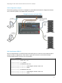
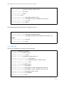
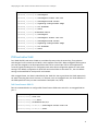
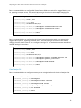
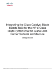
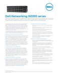
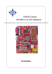
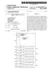
Deploying Dell PowerConnect 8100
and Cisco Catalyst Switches
Using the Dell PowerConnect 8100 Series switch with the Cisco Catalyst
WS-C6504-E
Andrew Berry
Victor Teeter
Kevin Locklear
Deploying the Dell PowerConnect 8100 with the Cisco Catalyst
This document is for informational purposes only and may contain typographical errors and
technical inaccuracies. The content is provided as is, without express or implied warranties of any
kind.
© 2013 Dell Inc. All rights reserved. Dell and its affiliates cannot be responsible for errors or omissions
in typography or photography. Dell, the Dell logo, and PowerEdge are trademarks of Dell Inc. Intel and
Xeon are registered trademarks of Intel Corporation in the U.S. and other countries. Microsoft, Windows,
and Windows Server are either trademarks or registered trademarks of Microsoft Corporation in the
United States and/or other countries. Other trademarks and trade names may be used in this document
to refer to either the entities claiming the marks and names or their products. Dell disclaims
proprietary interest in the marks and names of others.
January 2013 | Rev 1.1
ii
Deploying the Dell PowerConnect 8100 with the Cisco Catalyst
Contents
Introduction ............................................................................................... 4
Overview of VLANs .................................................................................................... 5
Creating and assigning VLANs ....................................................................................... 5
Management VLAN vs. SVI on the Cisco Catalyst 6500 .......................................................... 5
Dell PowerConnect 8100 CLI ....................................................................................... 6
Cisco Catalyst CLI .................................................................................................... 7
Access, trunk and general Switchport Modes ..................................................................... 8
VLAN configuration example....................................................................................... 9
Dell PowerConnect 8100 CLI ....................................................................................... 9
Cisco Catalyst CLI .................................................................................................. 10
PVID and native VLAN ............................................................................................... 11
Dell PowerConnect 8100 CLI ..................................................................................... 11
Cisco Catalyst CLI .................................................................................................. 12
Creating and connecting LAGs using LACP ...................................................................... 13
Enabling Spanning Tree – RSTP vs. RPVST+...................................................................... 13
Method 1: Portfast ................................................................................................ 14
Dell PowerConnect 8100 CLI ..................................................................................... 15
Cisco Catalyst CLI .................................................................................................. 15
Method 2: MSTP ................................................................................................... 16
Cisco proprietary protocols ........................................................................................ 16
Appendix A - Network switch versions ............................................................... 18
About Dell ................................................................................................ 18
iii
Deploying the Dell PowerConnect 8100 with the Cisco Catalyst
Introduction
New demanding campus workloads are compelling Network administrators to take another look at the
campus core/aggregation layers. The existing products like Cisco Catalyst 6500 platforms are aging and
cannot support the new deployments. Network administrators are exploring options to either reposition
the existing gear or replace it. Therefore, it is critical to understand how the newer campus
aggregation/core platforms interoperate or replace the Cisco Catalyst switches.
This document provides quick reference guidance in key areas for configuring or integrating the Dell
PowerConnect 8100 series switches with the Cisco Catalyst 6500 series. The most critical aspects and
differences with deploying VLAN (Virtual Local Area Networks) configuration, Link Aggregation,
preferred configuration for Spanning Tree and addressing Cisco proprietary protocols are covered in
this white paper.
The Dell PowerConnect 8100 series switches include the Dell PowerConnect 8132 (Figure 1),
PowerConnect 8132F (Figure 2), PowerConnect 8164 (Figure 3) and the PowerConnect 8164F (Figure 4).
Note: For this document the Cisco Catalyst WS-C6504-E was used.
Figure 1. Dell PowerConnect 8132
.
1
3
5
7
9
11
13
15
17
19
21
LNK 23 ACT
2
4
6
8
10
12
14
16
18
20
22
24
9
11
13
15
17
19
21
LNK 23 ACT
10
12
14
16
18
20
22
24
1
3
2
4
5
6
7
8
Dell PowerConnect 8164
1
3
5
7
9
2
4
6
8
10
11
13
Figure 4.
12
14
15
17
19
21
23
25
27
29
31
33
35
37
39
41
43
45
47
16
18
20
22
24
26
28
30
32
34
36
38
40
42
44
46
48
LNK
ACT
LNK
1
2
ACT
1
2
ACT
Dell PowerConnect 8164F
1
3
5
7
9
11
13
15
17
19
21
23
25
27
29
31
33
35
37
39
41
43
45
47
2
4
6
8
10
12
14
16
18
20
22
24
26
28
30
32
34
36
38
40
42
44
46
48
LNK
ACT
LNK
4
Deploying the Dell PowerConnect 8100 with the Cisco Catalyst
There are a couple of key differences between the Dell PowerConnect 8100 and the Cisco Catalyst:
•
Ports on the Cisco Catalyst are in shut mode by default, whereas ports on the PowerConnect
are active (no shut) by default. To use a Catalyst port, enable it with the no shut command.
•
The Dell PowerConnect 8100 is in Layer 2 mode by default whereas the Cisco Catalyst is in
Layer 3. The switchport command is required to put a Catalyst port into Layer 2, and routing
must be enabled on the PowerConnect 8100 to use Layer 3.
Overview of VLANs
VLANs (Virtual Local Area Networks) can be used to divide a large broadcast domain into smaller, more
manageable logical networks. When implementing VLANs, understand that the switch makes forwarding
decisions based on the Layer 2 header. These decisions are fast and provide for the division of the
different logical network segments, which in turn provides for easier management, better security, and
improved administration.
Creating and assigning VLANs
Creating VLANs on the Dell PowerConnect 8100 is simple and exactly the same on the Cisco Catalyst
WS-C6504-E. Both switches have the VLAN xx command available to manually create a VLAN and both
create a dynamic VLAN entry when a port is assigned a specific VLAN that has not yet been created.
The only difference between them regarding VLAN creation is that the Dell PowerConnect switches do
not support VTP (VLAN Trunking Protocol). VTP is a Cisco proprietary protocol (which is enabled by
default) that lets the user create a VLAN on one system, and by default these VLANs are automatically
created on all Cisco switches connected by a trunk. However, Dell PowerConnect switches do support
the standards based version of this feature with GVRP (Generic Attribute Registration Protocol (GARP)
VLAN Registration Protocol). These two protocols (VTP and GVRP) do not interoperate. If this
functionality is required throughout the subnet, then disable VTP on the Cisco Catalyst WS-C6504-E and
enable GVRP on both the Cisco Catalyst WS-C6504-E and Dell PowerConnect switches.
Note: Because most customers manually create each VLAN across the subnet, this feature is not a high
priority feature and enabling VTP on the Cisco Catalyst WS-C6504-E does not affect the Dell
PowerConnect switches.
Management VLAN vs. SVI on the Cisco Catalyst 6500
Management traffic is the basic messaging required to keep the network up and running. It uses
BPDUs, VTP packets, CDPs, keep alives, in addition to management access traffic such as HTML, CLI,
and SNMP. A Management VLAN is a VLAN specifically created for the use of managing the switch.
On a Dell PowerConnect 8100, VLAN 1 is known as the default VLAN because all ports on the switch are
assigned to it by default. It also is the default management VLAN on the switch. Configure this VLAN
(or any other VLAN created) as the in-band management VLAN by assigning it an IP address through the
console port on the switch. Once the IP address is assigned, telnet into the switch through any port
assigned to the VLAN to configure and manage the switch. This remote access provides the same
commands as if attached to the OOB (out-of-band) port.
Note: A management VLAN is the in-band option used when there is not a separate OOB (out-of-band)
network available.
5
Deploying the Dell PowerConnect 8100 with the Cisco Catalyst
In-band management traffic is mixed in with production network traffic, and is subject to all of the
filtering rules applied on a switched/routed port such as ACLs and VLAN tagging. See the Dell
PowerConnect 8100 User Guide for more information on OOB versus Management VLAN.
The Cisco Catalyst uses a similar setting known as SVI (switch virtual interface) to do remote switch
management. When activated, an SVI is used only for management and not for user traffic, just like
the management VLAN on the Dell switch.
Figure 5 shows the basic topology of a management VLAN that is configured in this example: creating
and then connecting a management VLAN and an SVI.
Management VLAN across a Dell PowerConnect 8100
Figure 5.
Both switches use the existing cables (that are carrying production traffic from switch to switch) to
carry in-band management traffic. The ports that carry switch-to-switch traffic are said to be in trunk
mode and by default accept and pass all management traffic once a management VLAN has been
defined. To create a Management VLAN or SVI, first create a VLAN interface and then add an IP address
to this interface.
Dell PowerConnect 8100 CLI
The example below shows the commands for setting up a management VLAN on the Dell PowerConnect
8100. After creating a username and password for remote access to the switch, create a VLAN and
assign it an IP address. Assign trunk ports to be attached to the Cisco Catalyst or other switch. Finally,
configure a single access port, though any number of ports may be added and used in the management
VLAN.
6
Deploying the Dell PowerConnect 8100 with the Cisco Catalyst
Run the commands below on the Dell PowerConnect 8100 switch to create a management VLAN, which
allows in-band management to the switch.
console#configure
console(config)#username admin1 password goodpa55 privilege 15
console(config)#vlan 50
console(config-vlan)#exit
console(config)#interface vlan 50
console(config-if-vlan50)#ip address 5.5.5.5 /24
console(config-if-vlan50)#exit
console(config)#interface tengigabitethernet 1/0/23
console(config-if-Te1/0/23)#switchport mode trunk
console(config-if-Te1/0/23)#exit
console(config)#interface tengigabitethernet 1/1/1
console(config-if-Te1/1/1)#switchport general allowed vlan add 50
console(config-if-Te1/1/1)#switchport general pvid 50
console(config-if-Te1/1/1)#switchport mode general
Running these commands opens a telnet session into the Dell PowerConnect 8100 switch through port
1/1/1 to management VLAN 50, using the username and password that were entered. In addition, port
1/0/23 is now ready to be connected to the Cisco Catalyst. Use the commands in the next section to
configure the Cisco Catalyst switch.
While it may be tempting to add a “switchport trunk native vlan 50” line to the port 1/0/23
configuration, this command will block control traffic on a Cisco Catalyst 6500, although this command
works between two 8100 switches, as well as between an 8100 and a Cisco Catalyst 3750. However,
native VLANs work differently on the Cisco Catalyst 6500; it is recommended that the Native and SVI
VLANs on the Cisco 6500 never be the same. If the port on the PowerConnect 8100 contains this line in
the configuration, and a ping is not going through to the Cisco Catalyst 6500, set the option back to the
default with the command: “switchport trunk native vlan 1”.
Cisco Catalyst CLI
Run the commands below on the Cisco Catalyst switch to create an SVI, which allows in-band
management to the switch.
cat6504E_1#configure terminal
Enter configuration commands, one per line.
End with CNTL/Z.
cat6504E_1(config)#interface vlan 50
cat6504E_1(config-if)#ip address 5.5.5.7 255.255.255.0
cat6504E_1(config-if)#exit
cat6504E_1(config)#vlan 50
7
Deploying the Dell PowerConnect 8100 with the Cisco Catalyst
cat6504E_1(config-vlan)#exit
% Applying VLAN changes may take few minutes.
Please wait...
cat6504E_1(config)#interface vlan 50
cat6504E_1(config-if)#no shut
cat6504E_1(config-vlan)#exit
cat6504E_1(config)#interface TenGigabitEthernet 2/1
cat6504E_1(config-if)#switchport
cat6504E_1(config-if)#switchport trunk encapsulation dot1q
cat6504E_1(config-if)#switchport mode trunk
cat6504E_1(config-if)#no shutdown
By connecting a cable from the Cisco Catalyst 6500 (port te2/1) to the PowerConnect 8100 (port
te1/0/23) it is possible to reach both switches through the management VLAN. In this example, telnet
5.5.5.5 to access the Dell PowerConnect switch, and telnet 5.5.5.7 to access the Cisco switch.
Optionally, remove default VLAN traffic from the management ports by using the following commands:
console(config-if-Te1/0/23)# switchport trunk allowed vlan remove 1
cat6504E_1(config-if)#switchport trunk allowed vlan remove 1
This command works the same on both the Dell PowerConnect 8100 and Cisco Catalyst 6500.
Note: Other basic setup configurations might be necessary for the Dell PowerConnect 8100 or Cisco
Catalyst 6500 switches, such as a DHCP option for management VLANs, assigning a domain server or
assigning a domain name, but these configuration steps are essentially the same for both switches and
are found in the Dell PowerConnect 8100 User Configuration Guide.
Access, trunk and general Switchport Modes
The Dell PowerConnect 8100 series switches can have each port configured in one of the following
modes (Dell.com, 2012):
Access
Access ports are intended to connect end devices to the switch or network. Many
times these end devices are PCs (personal computers) that cannot generate VLAN
tags on their network device link. Access ports only have one VLAN and any
traffic on this port is sent and received with no VLAN tagging. With an access
port, incoming tagged packets are dropped, and any VLAN information is cleared
from the frame before it is sent to an end device.
Trunk
Trunk-mode ports are intended to link switches together. Trunk ports work with
both tagged and untagged packets. Tagged packets received on a trunk port are
forwarded on the VLAN contained in the tag. Untagged packets are forwarded on
the native VLAN. Trunk mode includes all VLANs by default.
General
This mode is specific to the PowerConnect switches. Ports in general mode are
either access and/or trunk ports depending on their tagged state.
8
Deploying the Dell PowerConnect 8100 with the Cisco Catalyst
VLAN configuration example
The following topology overview is an example of a much abbreviated network configuration between
two (2) end-user systems, the campus switch, and the core.
Example of access, and trunk VLANs
Figure 6.
Dell PowerConnect 8100 CLI
Run the commands below on the Dell PowerConnect 8100 switch to create an access mode switchport
going to a client (or edge) device. Then create a 2-port LACP LAG with a trunk mode switchport
carrying VLANs between it and the Cisco Catalyst 6504.
console#configure
console(config)#vlan 100, 101
console(config-vlan)#exit
console(config)#interface te1/0/1
console(config-if-Te1/0/1)#switchport access vlan 100
console(config-if-Te1/0/1)#exit
console(config)#interface te1/0/2
console(config-if-Te1/0/1)#switchport access vlan 101
console(config-if-Te1/0/1)#exit
9
Deploying the Dell PowerConnect 8100 with the Cisco Catalyst
console(config)# interface
range te1/0/47-48
console(config-if)#channel-group 1 mode active
console(config-if)#no shut
console(config-if)#exit
console(config)#po1
console(config-if-Po1)#switchport mode trunk
console(config-if-Po1)#switchport trunk allowed vlan 100,101
console(config-if-Po1)#no shut
console(config-if-Po1)#exit
OR using general Mode changing only the configuration for Po1
console(config)#po1
console(config-if-Po1)#switchport mode general
console(config-if-Po1)#switchport general allowed vlan add 100,101
tagged
console(config-if-Po1)#no shut
console(config-if-Po1)#exit
Cisco Catalyst CLI
Here are the commands to run on the Cisco Catalyst 6504:
Cat6504E_1#configure terminal
Cat6504E_1(config)#vlan 100,101
Cat6504E_1(config-vlan)#exit
Cat6504E_1(config)#interface range te2/1-2
Cat6504E_1(config-if-range)#switchport
Cat6504E_1(config-if-range)#channel-group 1 mode active
Cat6504E_1(config-if-range)#exit
Cat6504E_1(config)#interface po1
Cat6504E_1(config-if)#switchport
Cat6504E_1(config-if)#switchport trunk encapsulation dot1q
Cat6504E_1(config-if)#switchport trunk allowed vlan 100,101
Cat6504E_1(config-if)#switchport mode trunk
Cat6504E_1(config-if)#no shutdown
Cat6504E_1(config-if)#exit
10
Deploying the Dell PowerConnect 8100 with the Cisco Catalyst
Cat6504E_1(config)#interface te2/7
Cat6504E_1(config-if)#switchport
Cat6504E_1(config-if)#switchport access vlan 100
Cat6504E_1(config-if)#switchport mode access
Cat6504E_1(config-if)#spanning-tree portfast edge
Cat6504E_1(config-if)#no shutdown
Cat6504E_1(config-if)#exit
Cat6504E_1(config)#interface te2/8
Cat6504E_1(config-if)#switchport
Cat6504E_1(config-if)#switchport access vlan 101
Cat6504E_1(config-if)#switchport mode access
Cat6504E_1(config-if)#spanning-tree portfast edge
Cat6504E_1(config-if)#no shutdown
Cat6504E_1(config-if)#exit
PVID and native VLAN
Port VLAN ID (PVID) and native VLANs are considered by many to be the same thing. Every physical
switching port on the switch has a VLAN ID, which equates to the PVID. When untagged frames ingress a
port they are assigned to the VLAN specified as the PVID or native VLAN. PVID is more applicable to
access and general mode ports for configuration and native VLAN configuration applies to trunk mode
settings. The default configuration for both PVID and native VLANs on the switch is 1, but this default
setting can be modified for each specific environment.
With a tagged frame, the VLAN is identified by the VLAN ID in the tag and have this VLAN respectively
set when traversing the switch. However, to reiterate, with an untagged frame, the VLAN identifier is
the PVID specified for the port that received the frame (Dell.com, 2012).
Dell PowerConnect 8100 CLI
Run the commands below to configure Dell PowerConnect 8100 series switch for an untagged VLAN on
port 1.
console#configure
console(config)#vlan 100
console(config-vlan)#exit
console(config)#interface te1/0/1
console(config-if-Te1/0/1)#switchport access vlan 100
console(config-if-Te1/0/1)#exit
11
Deploying the Dell PowerConnect 8100 with the Cisco Catalyst
Run the commands below to configure Dell PowerConnect 8100 series switch for a tagged VLAN on port
10, egressing to another switch. The native VLAN setting is also shown in the example changing from
the default value of 1 to a configured setting of 2.
console#configure
console(config)#vlan 2,100
console(config-vlan)#exit
console(config)#interface te1/0/10
console(config-if-Te1/0/10)#switchport trunk allowed vlan 100
console(config-if-Te1/0/10)#switchport trunk native vlan 2
console(config-if-Te1/0/10)#switchport mode trunk
console(config-if-Te1/0/10)#exit
Run the commands below to configure the Dell PowerConnect 8100 series switch for a general mode
tagged VLAN on port 10, egressing to another switch. The PVID setting is also shown in the example
changing from the default value of 1 to a configured setting of 2. The similarities between native VLAN
and PVID settings is shown here.
console#configure
console(config)#vlan 2,100
console(config-vlan)#exit
console(config)#interface te1/0/10
console(config-if-Te1/0/10)#switchport general allowed add vlan 100
console(config-if-Te1/0/10)#switchport general pvid vlan 2
console(config-if-Te1/0/10)#switchport mode general
console(config-if-Te1/0/10)#exit
Cisco Catalyst CLI
Run the commands below to configure an access port on a single interface of the Cisco Catalyst 6504.
Cat6504E_1(config)#interface te2/7
Cat6504E_1(config-if)#switchport
Cat6504E_1(config-if)#switchport access vlan 100
Cat6504E_1(config-if)#switchport mode access
Cat6504E_1(config-if)#spanning-tree portfast edge
Cat6504E_1(config-if)#no shutdown
Cat6504E_1(config-if)#exit
12
Deploying the Dell PowerConnect 8100 with the Cisco Catalyst
Run the commands below to configure a trunk port on a single interface with the native VLAN being
configured for 2.
Cat6504E_1(config)#interface te2/6
Cat6504E_1(config-if)#switchport
Cat6504E_1(config-if)#switchport trunk encapsulation dot1q
Cat6504E_1(config-if)#switchport trunk allowed vlan 100,101
Cat6504E_1(config-if)#switchport trunk native vlan 2
Cat6504E_1(config-if)#switchport mode trunk
Cat6504E_1(config-if)#no shutdown
Cat6504E_1(config-if)#exit
Creating and connecting LAGs using LACP
LACP provides a method of bundling several connections together as a logical link and provides a logical
link indicator for this set of connections. In addition, there may be a need to have additional
connectivity between two switches for throughput and redundancy. More than one connection can then
be bundled as a LAG (link aggregation group). With this LACP type LAG in place, if one or the other of
the switches were to crash but yet leave the physical link up, an LACP timeout would signal that the
link is disconnected. If LACP were not used in this situation, there would be no indication of the switch
on the other end malfunctioning.
An example of CLI necessary to create and assign port-channels (LAGs) is found on page 9 and 10. The
only note to remember is that the Cisco switches support a proprietary form of LAGs with the PaGP
feature that the Dell PowerConnect switch does not support.
Enabling Spanning Tree – RSTP vs. RPVST+
Spanning tree protocol (STP) is a Layer 2 protocol that protects a network from loops and broadcast
storms. There are several spanning tree methods that can be implemented, but not all are compatible
with each other, from one equipment manufacturer to the next.
For example, standards-based switches like the Dell PowerConnect 8100 do not use Cisco proprietary
protocols (PVST, RPVST, CDP, VTP, and so on.). For this reason, it is important to understand a few
terms around standard and non-standard spanning tree.
STP
(based on IEEE 802.1d) – Spanning Tree Protocol, or simply Spanning Tree. A
standards-based protocol that prevents physical loops and broadcast storms on a
network. Available on the Dell PowerConnect 8100.
13
Deploying the Dell PowerConnect 8100 with the Cisco Catalyst
RSTP
(Based on IEEE 802.1w) - Rapid STP. A standards-based protocol that is considerably
faster at network convergence (after a topology change) than its STP predecessor in
most network implementations. It is the default for the Dell PowerConnect 8100,
and is compatible with STP.
MST
(Based on IEEE 802.1s) – Multiple Spanning Tree protocol or MSTP. Allows for
multiple instances of spanning tree across a network. Each instance contains one or
more VLANs. Enables load balancing of traffic through the network while minimizing
CPU cycles.
PVST+
Per VLAN spanning Tree. A Cisco proprietary protocol similar to STP that allows
each VLAN to run its own instance of Spanning Tree. It is available on the Cisco
Catalyst 6500.
RPVST+
Rapid PVST+. A Cisco proprietary protocol that is considerably faster at network
convergence (after a topology change) than its PVST+ predecessor in most network
implementations. It is the default on the Cisco Catalyst 6500.
CST
Common Spanning Tree. A single spanning tree instance for an entire network
regardless of the number of VLANs on that network.
BPDU
Bridge Protocol Data Unit. Packets that are exchanged between network devices to
help detect loops in a network.
802.1d
IEEE standard that allows spanning tree ports to be in one of the following states:
listen, learn, forward, block, or disabled.
802.1w
IEEE standard that allows spanning tree ports to be in one of the following states:
learn, forward, or discard. Discard replaces listen, block, and disable states. A
great improvement in convergence speed over 802.1d.
801.1s
IEEE standard that allows for multiple instances of spanning tree across a physical
bridged network.
Attempting to recover from a failed network device is a common difficulty that arises on a Cisco
Catalyst network using RPVST+, when standards-based edge devices are attached in a redundant loop
topology. RPVST+ ports from the Cisco Catalyst switch that are connected to the Dell PowerConnect
8100 no longer receive BPDUs from VLANs not in the CST. This causes a delay in network activity until
the forward-delay timer expires.
To minimize downtime when using Cisco proprietary protocols (PVST+, RPVST+) together with standard
protocols (STP, RSTP) on the Dell PowerConnect switches, additional instruction on the network is
required. Below are two common methods to get the job done.
Method 1: Portfast
Ports on the Cisco Catalyst switch that are directly connected to the Dell PowerConnect 8100 can be
forced into forwarding state after a network change by using the portfast option. The rapid spanning
tree protocols quickly blocks any loops detected in the network during convergence. The block occurs
at a location away from the Cisco core network. In this scenario, the link between the Dell
PowerConnect switches is blocked. This is the most recommended method.
14
Deploying the Dell PowerConnect 8100 with the Cisco Catalyst
Recommended Spanning Tree method: Portfast
Figure 7.
Dell PowerConnect 8100 CLI
No changes are required to the Dell PowerConnect 8100 for using this method.
Cisco Catalyst CLI
Run the commands below to enable portfast on all interfaces that are connected to the Dell
PowerConnect 8100s.
cat6504E_1#configure terminal
Enter configuration commands, one per line.
End with CNTL/Z.
cat6504E_1(config)#interface tengigabitethernet 2/5
cat6504E_1(config-if)#spanning-tree portfast network
Review the bridge priority configurations on each switch to make sure the root bridge of the spanning
tree is properly placed. Adjust the root bridge priorities higher or lower to place the root bridge within
the Cisco environment.
For Dell, use the command
console(config)#spanning-tree priority xxxxx
On the Cisco Catalyst the commands that can be used are
cat6504E_1(config)#spanning-tree vlan 1 priority xxxxx
or
cat6504E_1(config)#spanning-tree vlan xx root primary
.
.
.
.
…
15
Deploying the Dell PowerConnect 8100 with the Cisco Catalyst
Consult the User Guides for each device for more information on bridge priority settings.
Method 2: MSTP
In addition, users can minimize downtimes by using a standard protocol on the Cisco Catalyst. Spanning
tree modes available on the Cisco Catalyst WS-C6504-E with IOS 12.2(33)SXI4a are MST, PVST, and
Rapid-PVST. Of the three, only MST is an IEEE standard protocol. MST is also the only protocol
available on both the Cisco Catalyst and the Dell PowerConnect 8100.
This option is less desirable because it requires migrating exiting Cisco devices over to MST, which were
previously running a Cisco proprietary spanning tree protocol (PVST+ or RPVST+). Such a migration
would typically require some reconfiguration and possible topology redesign. Consult the User Guides
for your devices on how to set up MST.
Cisco proprietary protocols
Network administrators often run into problems receiving multiple Cisco proprietary protocols on
standards based switches, which causes unexpected results on the network. Therefore, Dell
PowerConnect has developed an easy way to block Cisco protocols as necessary. By creating built-in
ACLs (Access Control Lists) that block individual Cisco protocols on each port, the user can now filter
out unwanted packets from their network. For example, use the following command to enable
automatic filtering of CDP packets on the interface:
console(config)#interface gi1/0/3
console(config-if)#service-acl input blockcdp
console(config-if)#exit
The no service-acl input command removes this filtering for the interface.
In the same way, administrators can block the other proprietary protocol packets individually (cdp,
vtp, dtp, pagp, udld, sstp) as shown below replacing the ( ) with the keyword:
console(config)#interface gi1/0/3
console(config-if)#service-acl input ( )
-options put in place of parenthesis
blockcdp
blocks all cdp packets on this interface
blockvtp
blocks all vtp packets on this interface
blockdtp
blocks all dtp packets on this interface
blockpagp
blocks all pagp packets on this interface
blockudld
blocks all udld packets on this interface
blocksstp
blocks all sstp packets on this interface
blockall
blocks all cisco proprietary protocols on this interface
Use one or more of these filters on each port by running a mix of options on a single line, (for example,
service-acl input blockpagp blockudld), or simply use the blockall option to block all Cisco protocols on
the port.
Note: These interface ACLs take precedence over any global configuration that may be active on the
switch (for example, if a form of CDP is globally running on the switch, the service-acl blockcdp
16
Deploying the Dell PowerConnect 8100 with the Cisco Catalyst
interface option enforces the dropping of CDP packets for the ingress on this interface even if the
global setting is enabled).
For more information, see the Link Local Protocol Filtering section in the PowerConnect 8100 User’s
Configuration Guide.
17
Deploying the Dell PowerConnect 8100 with the Cisco Catalyst
Appendix A - Network switch versions
Version information for the network switches used in creating this document are as follows:
Network switch
Dell PowerConnect 8100
Cisco Catalyst WS-C6504-E
Software Version
5.0.0.4
IOS 12.2(33)SXI4a;
About Dell
Dell (NASDAQ: DELL) is a leading technology provider to commercial and public enterprises around the
world.
18